

Page 1
Product Information
DT Accessories
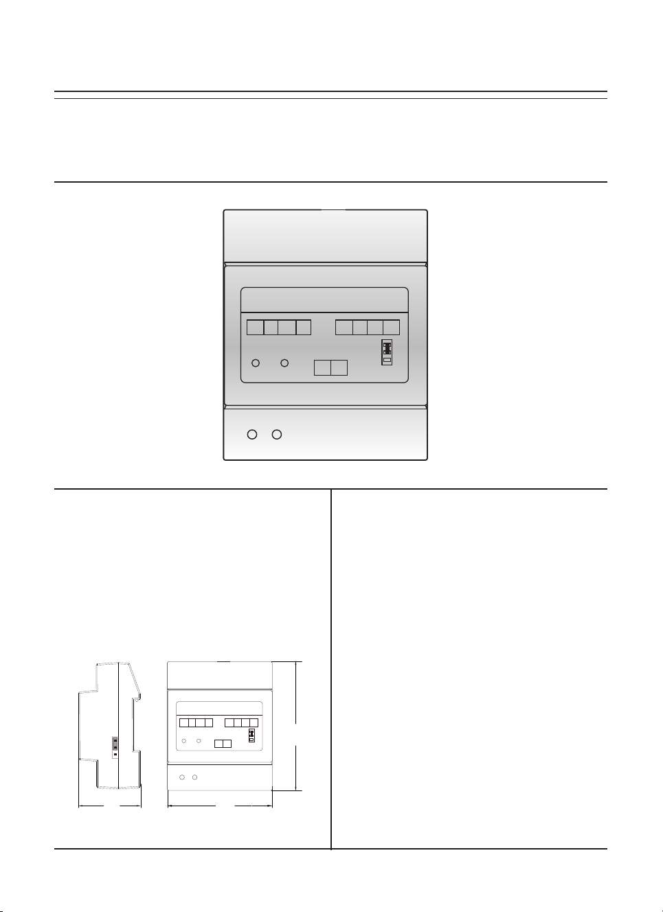
DT-RLC
DT-RLC
GND NO COM NC
POWER IN-USE
BUS BUS
DESCRIPTION
The relay actuator DT-RLC is a unlock function
device designed for DT system to control door
locks.
DIMENSION
2-WIRE SYSTEM
12V S2 S1 GND
1
2
RISER
3
FEATURES
► Allows to open gate door locks;
► Support high power-consumption lock;
► With congurable unlock timed output;
► Support exit control button.
1
2
3
45mm
DT-RLC
GND NO COM NC
POWER IN-USE
2-WIRE SYSTEM
12V S2 S1 GND
BUS BUS
71mm
1
2
3
RISER
89mm
Page 2
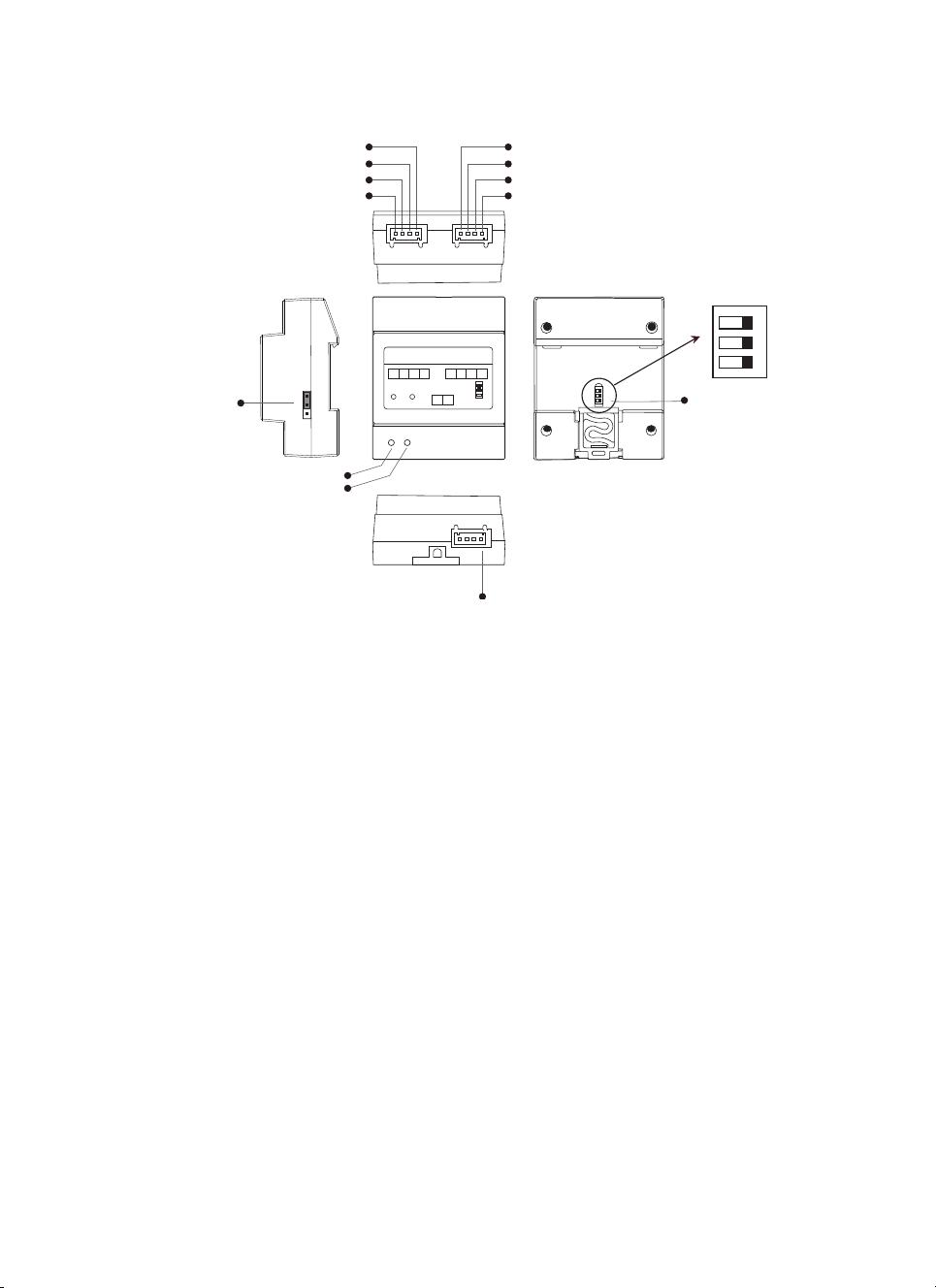
1.Parts and Functions
12V
S2
S1
GND
1
2
3
lock Control
Jumper
1
2
3
POWER
IN-USE
COM
GND
NC
NO
2-WIRE SYSTEM
DT-RLC
GND NO COM NC
12V S2 S1 GND
RISER
BUS BUS
POWER IN-USE
+12V:12V power output. Can be used to power the lock.
S2:Reserved.
DIP
ON
2 3
1
1 2 3
DIP
S1:Exit button contact. Short this contact and the GND to unlock.
GND:The common Ground of the other 3 contacts: S1, S2 and +12V.
NC:The normally-closed contact to COM.
COM: The common contact of the unlock relay.
NO: The normally-open contact to COM.
Lock Control Jumper: To select the lock type: see section 5,6.
POWER:Working indicator,it will light up when plugs in power supply.
IN-USE:Unlock indicator,it will light up when unlock.
Bus:Connect to the bus line, no polarity.
DIP :Used for setting the address of the RLC.
Page 3

2. Unit Mounting
2-WIRE SYSTEM
DT-RLC
GND NO COM NC
POWER IN-USE
BUS BUS
12V S2 S1 GND
RISER
1
2
3
DIN Rail Mounting
3. Specification
●Power Supply : DC 24V;
●Unlocking Time: 1~30s(Default 1s);
●Lock Power supply: 12Vdc, 450mA(Internal Power);
●Working temperature: -15ºC ~ +55ºC;
●Dimension: 89(H)X71(W)X45(D)mm.
4. Packing Information
Dimensions: 100(H)×85(W)×60(D)mm
Gross Weight: 0.17Kg
Carton: 415 (H)×360 (W)×265 (D)mm
Quantity: 60PCS
 Loading...