

Page 1
IP Gateway Converter Operating Instructions
2-Wire System
Power In-Use
IP Converter
Model: IPG-Gateway
Net Video
CHECK CALL
DT-CHK IP-CHK
Indicators Buttons
1. Introduction:
Version 1.0 / 201704
The IP gateway converter is an essential unit for
2-wire IP hybrid network system, for the purpose of
a grouped building system for centralized management.
The features are as follows:
• Max.199 gateway are supported in system
• RJ45 LAN ethernet connection
• IP_NODE_ID setting by DIP switches
• Free of PC conguration in regular use
• Diagnose assistance for convenient maintenance
• Working state indicators(on/off line, activity states
etc)
IP_NODE_ID is the critical address in 2-wire IP system, instead of tranditional IP address configura-
tions. All IP devices in a network system must be
set differently.
DIP switches are for IP_NODE_ID address setting
by manual, range is limited from 01 to 63. For larger
system with more than 63 gateway units, set the
DIP switchers to 00, and then use configuration
software to set IP_NODE_ID from 64 to 199.
Unless modifed by means of configuration soft-
ware, DT-IPG use default IP address settings as:
IP segment: 192.168.243
IP subnet mask: 255.255.255.0
Gateway: 192.168.243.200
IP_NODE_ID will be the IP address last segment
number, for example:
If a DT-IPG DIP switches are set to IP_NODE_ID=12,
this DT-IPG IP address will be 192.168.243.12.
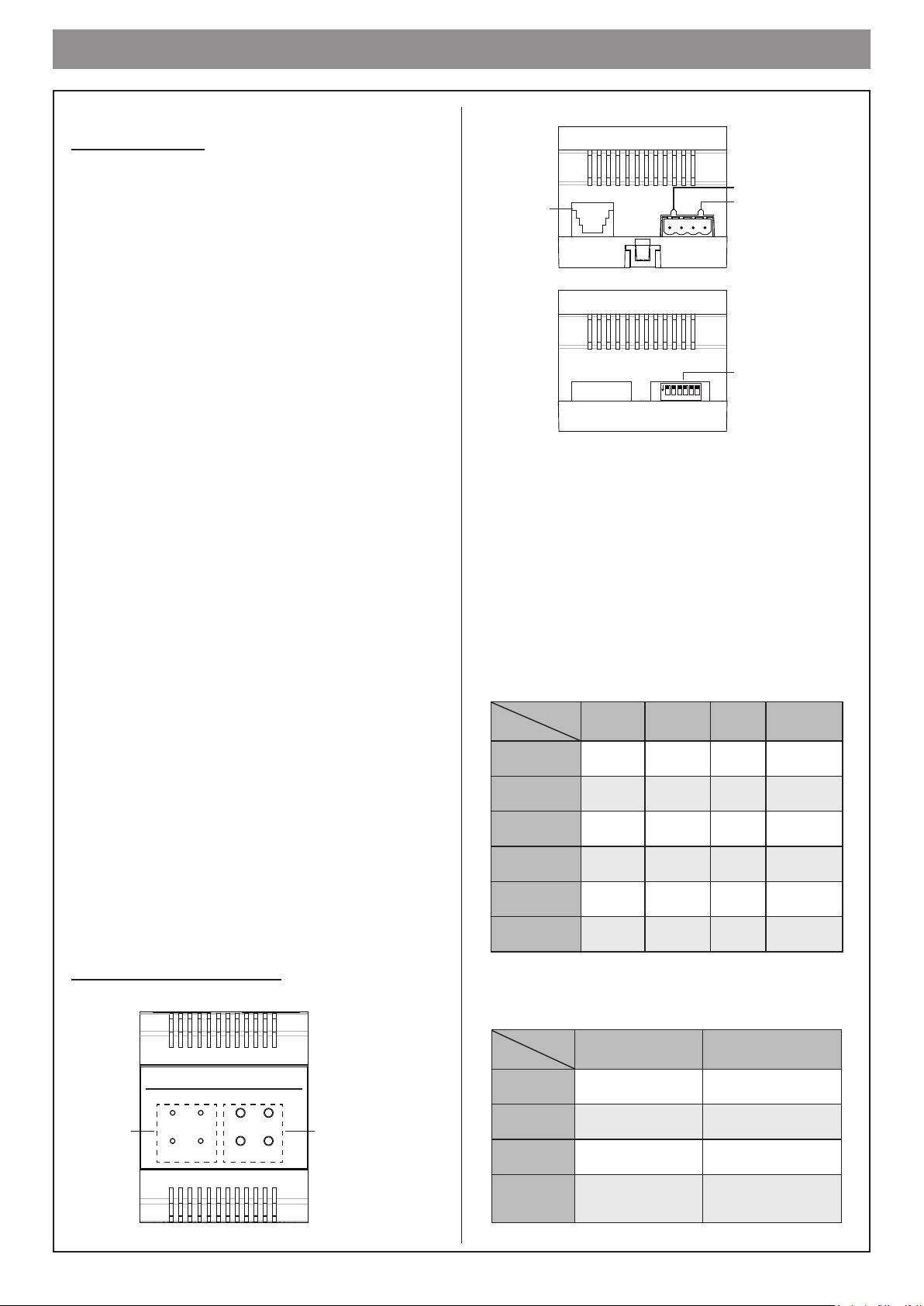
2. Terminal Description:
BUS(DS)
RJ45
ON
1 2 3 4 5 6
BUS(IM)
DIP Switch
Connection Port
RJ45: Network connection terminal.
BUS(IM): Indoor monitor connection terminal.
BUS(DS): Door station connection terminal.
Indicators
The system status can be indicated by LED.
Please refer to the followings in detail.
LED
Status
OFF
ON
Fast
Flashing
Normal
Flashing
Short irregular
Flashing
Long irregular
Flashing
Power In-use Net Video
Power
OFF
Power
ON
Device
ERR
Boot
Kernal
Boot-app CALL Busy — —
FW update — — —
Idle
Talking
OUT-CALL
Caller
IN-CALL
Becalled
No
Ethernet
EthernetOKNetwork
— VD_C&S
—
VD_Idle
Video Server
Network
Video Client
Buttons
Status
Buttons
2-Wire System
Model: IPG-Gateway
Indicators Buttons
Power In-Use
Net Video
We reserve the right to modify the specication in this manual at any time without notice.
IP Converter
CHECK CALL
DT-CHK IP-CHK
CHECK
CALL
DT-CHK
IP-CHK
TIP/RING
Enforce call
Online check for
2-wire system devices
Online check for IP
network devices
One Press Long Press
Download namelist to
DS&CDS
Download namelist to
monitor
Restore factory setting
Check IP
Check network quality
Check source download
Page 2

DIP Setting
DIP setting is for IP address setting, range is
01~63. Please refer to the followings in detail.
ON
1 2 3 4 5 6
01
ON
1 2 3 4 5 6
02
ON
1 2 3 4 5 6
03
ON
1 2 3 4 5 6
04
ON
1 2 3 4 5 6
05
ON
1 2 3 4 5 6
14
ON
1 2 3 4 5 6
15
ON
1 2 3 4 5 6
16
ON
1 2 3 4 5 6
17
ON
1 2 3 4 5 6
18
ON
1 2 3 4 5 6
27
ON
1 2 3 4 5 6
28
ON
1 2 3 4 5 6
29
ON
1 2 3 4 5 6
30
ON
1 2 3 4 5 6
31
ON
1 2 3 4 5 6
40
ON
1 2 3 4 5 6
41
ON
1 2 3 4 5 6
42
ON
1 2 3 4 5 6
43
ON
1 2 3 4 5 6
44
ON
1 2 3 4 5 6
53
ON
1 2 3 4 5 6
54
ON
1 2 3 4 5 6
55
ON
1 2 3 4 5 6
56
ON
1 2 3 4 5 6
57
4. Wiring:
ON
1 2 3 4 5 6
IP Address
2-Wire System
Model: IPG-Gateway
Power In-Use
Net Video
IP Converter
CHECK CALL
DT-CHK IP-CHK
BUS(DS)
BUS(IM)
ON
1 2 3 4 5 6
06
ON
1 2 3 4 5 6
07
ON
1 2 3 4 5 6
08
ON
1 2 3 4 5 6
09
ON
1 2 3 4 5 6
10
ON
1 2 3 4 5 6
11
ON
1 2 3 4 5 6
12
ON
1 2 3 4 5 6
13
ON
1 2 3 4 5 6
19
ON
1 2 3 4 5 6
20
ON
1 2 3 4 5 6
21
ON
1 2 3 4 5 6
22
ON
1 2 3 4 5 6
23
ON
1 2 3 4 5 6
24
ON
1 2 3 4 5 6
25
ON
1 2 3 4 5 6
26
3. Mounting:
ON
1 2 3 4 5 6
32
ON
1 2 3 4 5 6
33
ON
1 2 3 4 5 6
34
ON
1 2 3 4 5 6
35
ON
1 2 3 4 5 6
36
ON
1 2 3 4 5 6
37
ON
1 2 3 4 5 6
38
ON
1 2 3 4 5 6
39
ON
1 2 3 4 5 6
45
ON
1 2 3 4 5 6
46
ON
1 2 3 4 5 6
47
ON
1 2 3 4 5 6
48
ON
1 2 3 4 5 6
49
ON
1 2 3 4 5 6
50
ON
1 2 3 4 5 6
51
ON
1 2 3 4 5 6
52
ON
1 2 3 4 5 6
58
ON
1 2 3 4 5 6
59
ON
1 2 3 4 5 6
60
ON
1 2 3 4 5 6
61
ON
1 2 3 4 5 6
62
ON
1 2 3 4 5 6
63
To Monitors / Branch Distributor
To Door Station / Power Supply BUS(IM)
To Ethernet
5. Specication:
Power: 2-wire bus (26V, no-polarity)
Consumption current: Standby 70mA,
maximum 190mA
LAN Ethernet: 10BASE-T, 100BASE-TX
Audio codec: G.711(64Kbps)
Video codec : H.264/AVC (VGA, QVGA)
Network Protocol: IPv4, TCP, UDP, RTSP, RTP,
RTCP, IGMP, DHCP, NTP
Operating temperature: 0 °C ~ +40 °C
Dimension: 72*90*60mm
Step1: Mount the din rail to the wall with screws;
Step2: Pull down the mounting buckle,then hang
the unit on din rail.
6. Warning:
- The unit can only be used in 2-wire products supplied by our company.
Din rail
- Don’t connect the unit with any non-specified
power source. Fire or electric shock could result.
- Don’t dismantle or alter the unit. Fire or electric
shock could result.
- The unit must be installed and wired by a qualied
technician.
- Keep the unit away from water or any other liquid.
Din rail
Mounting Buckle
We reserve the right to modify the specication in this manual at any time without notice.
We reserve the right to modify the specication in this manual at any time without notice.
Fire or electric shock could result.
 Loading...