

Page 1
DT-ENG-608-V1 / 201708
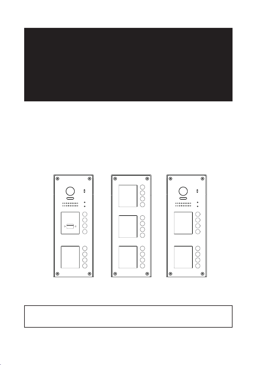
2 WIRE SYSTEM
DT608 Series
Fisheye door station with proximity access control
USER MANUAL
RF CARD
EP608-S12DT608/ID/FE-S8 DT60C-S8
• Please read this manual carefully to ensure safe and correct operation.
• Keep this manual well for future reference.
Page 2

CONTENTS
PARTS AND FUNCTIONS ..................................................................................... 3
Part Names............................................................................................................. 3
Mounting ................................................................................................................. 3
Terminal Description ............................................................................................... 4
BASIC FUNCTIONS .............................................................................................. 5
Unlock Operations .................................................................................................. 5
Fisheye Camera ..................................................................................................... 5
External Motion Detection ...................................................................................... 5
SETUP INSTRUCTIONS ........................................................................................ 6
Functions Setting Up .............................................................................................. 6
Setting Door Station Address .................................................................................7
Setting Door Station Calling Mode ......................................................................... 7
Setting Camera N/P Standard ................................................................................ 9
Setting Prompt Voice .............................................................................................. 9
Setting Prompt Voice Volume ................................................................................ 10
Setting Unlock Mode ............................................................................................. 10
Setting Unlock Time............................................................................................... 11
Setting Nameplate Illumination Mode .................................................................... 11
Setting Night View LED Illumination Mode ............................................................ 12
Setting Ring-back Tone ......................................................................................... 12
Setting Image Display Mode.................................................................................. 13
RAINY_COVER Congure .................................................................................... 14
Registering ID Card ............................................................................................... 15
Restore To Default ................................................................................................. 17
WIRING ................................................................................................................. 18
Connecting Electric Lock(NOT RECOMMENDED). See Next page ..................... 18
Connecting Multi Door Stations ............................................................................. 19
Eight Apartments Connection ................................................................................ 21
APPENDIX ............................................................................................................ 22
Precautions............................................................................................................ 22
Specication .......................................................................................................... 22
Cables and Requirments ....................................................................................... 23
Page 3
PARTS AND FUNCTIONS
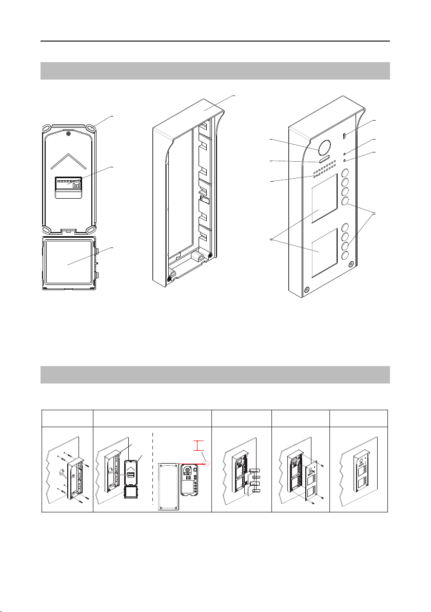
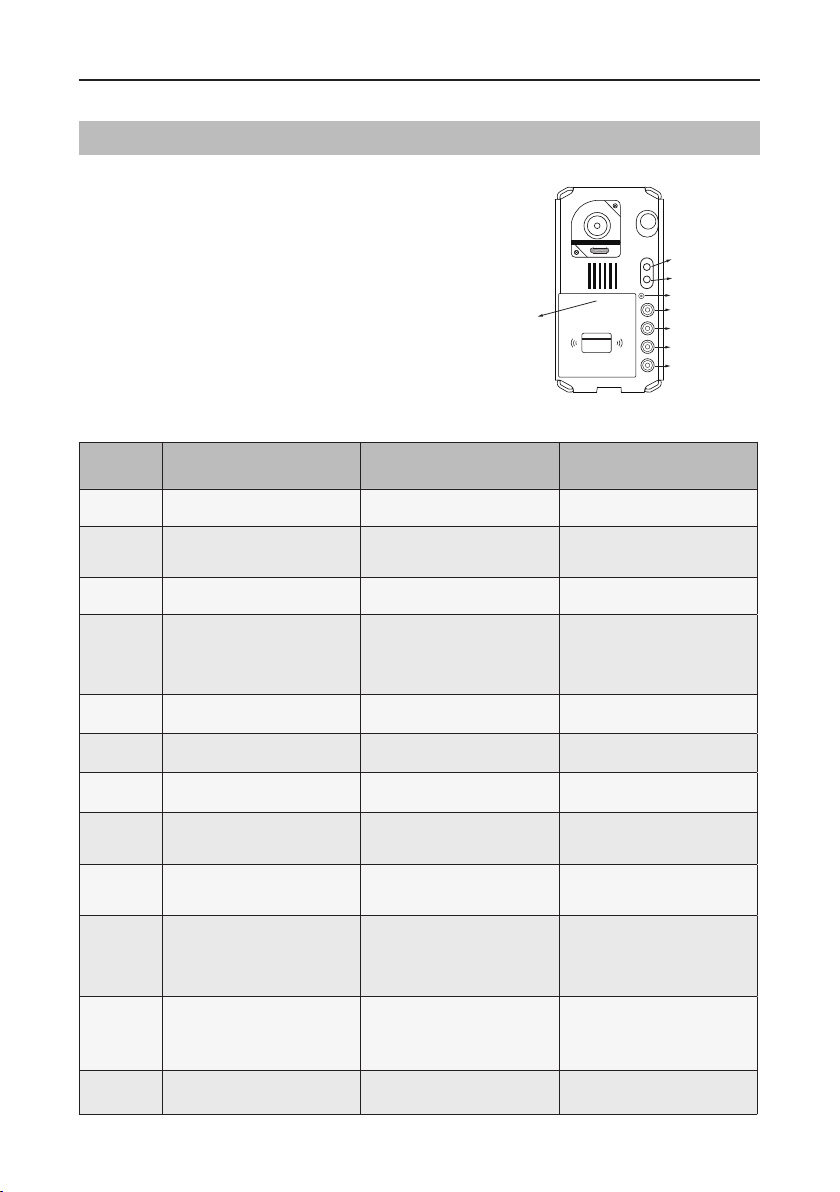
Part Names
[9]
[10]
[11]
[12]
[1] Microphone
[2] UNLOCK indicator
[3] CALL indicator
[4] Call button
[5] Nameplate
[6] Speaker
[7] Night view LED
[8] Camera lens
[9] Rainy cover
Mounting
The installation height is suggested to 145~160cm.
[8]
[7]
[6]
[5]
[1]
[2]
[3]
[4]
[10] Mounting hook
[11] Connection port
[12] External key module
1 2 3 4 5
The distance between
the top of main unit
Rainy cover
Main unit
and rain cover should
be not less than 0.12in.
Rainy cover
Main unit
≥0.12in
AcDbMLeader (ACDB_MLEADER_CLASS)
AcDbMLeader (ACDB_MLEADER_CLASS)
AcDbMLeader (ACDB_MLEADER_CLASS)
AcDbMLeader (ACDB_MLEADER_CLASS)
1. Drill holes in the wall to match the size of screw stoppers, then attach the rainy cover to the
wall.
2. Connect the cable correctly, and attach the main unit to the rainy cover. The distance between
the top of main unit and rain cover should be not less than 3mm.
-3-
Page 4
PARTS AND FUNCTIONS
3. Install the name plate.
4. Attach the front panel to the rainy cover.
5. Use the special screwdriver and the screws to x the panel.
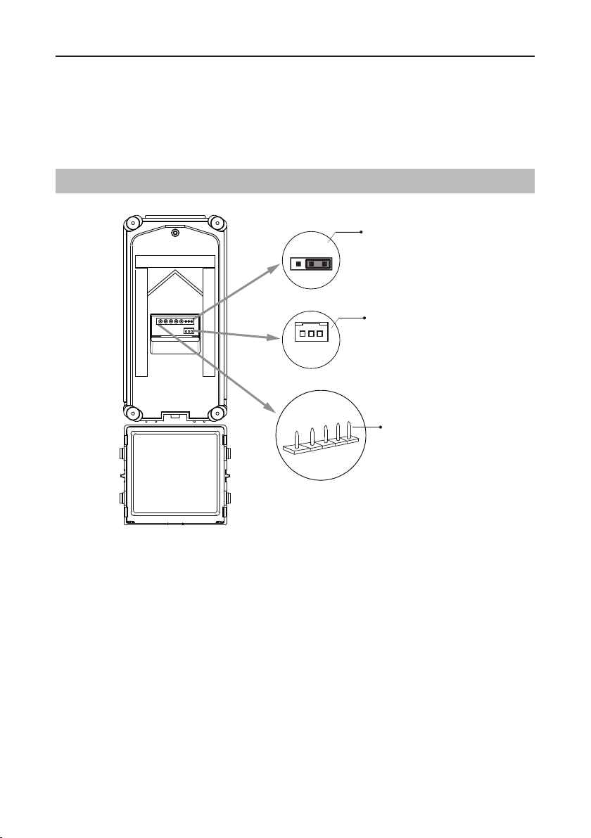
Terminal Description
1 2 3
PIR
GND
+12V
S-
S+
PL
L2
L1
Lock Control Jumper
3P Connect Port
Main Connect Port
Lock Control Jumper:
3P Connect Port:
To select the lock type.
1. If the external key module is detected online, the port will be
automatically as a communication port;
2. If there is no the external key module, it will check whether the PIR function is enabled. If the
PIR function is enabled, it will be as the detection port of the PIR;
3. If above cases are not activated, it can be used as exit button port.
Main Connect Port:
L1,L2:
•
•
•
•
Connect to the bus line, no polarity.
PL:
External lock power input, connect to the power positive(power +).
S+:
Lock power(+) output.
S-:
Lock power(-) output, connect to the power(-) input of locks(only when using the door
To connect the bus line and the electronic locks.
station to power the locks, if using the external power supply for the locks, the S- will not be
connected).
-4-
Page 5
BASIC FUNCTIONS
detector
Unlock Operations
Unlocking of ID Card
When the registered user card has been shown to ID card window, the UNLOCK indicator lights
up, the buzzer sounds,and the electric door strike is unlocked.
• If show the authorized user card,the buzzer will sound of beep+,and the UNLOCK indicator
will light up.
• If show the unauthorized user card,the buzzer will sound of beep,beep,beep.
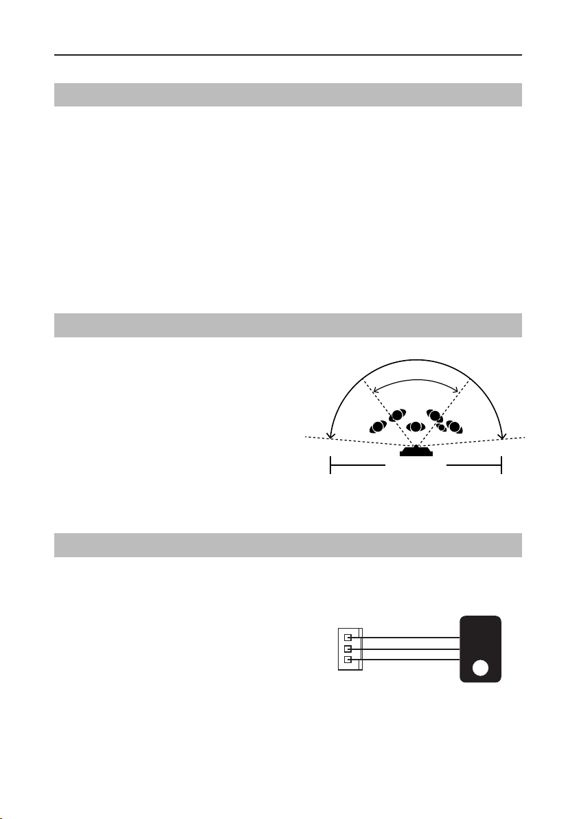
Fisheye Camera
Please note that this function requires the
monitor with sheye function to support.
The angle view is 1700,visitors in this angle
view can be seen clearly and can be zoomed
to see individuals up close via indoor monitor
with sheye function.
Standard
door station angle
DT608
1700 door camera angle
(Wide angle view shown)
External Motion Detection
The door station is equipped with a terminal to
connect external motion detector.
If the external motion detector is connected
to the system,following functions will be effec-
tive:
If detect someone passing by, the door station
can be activated operation to unlock or turn
on light.
* Please contact with supplier for more details about
detector connection.
12V
GND
PIR
Motion
-5-
Page 6
SETUP INSTRUCTIONS
Functions Setting Up
This section explains the settings of each
function, please refer to the following table:
To perform the settings for the function
you want,you should move away the metal
front panel. Please refer to the sketch
map.
Each operation is indicated by the lighting
up of the
LED
indicator on the unit, and by
the sounding of the buzzer.
Order Setting items Setting range Default value
1 Setting door station address 0~3 0
2
3 Setting camera N/P standard N/P standard P standard
Setting door station
calling mode
Standard/Group calling mode Standard calling mode
LED_NAME
RF CARD
Main unit
LED_UNLOCK
LED_CALL
KEY_SET
KEY_4
KEY_3
KEY_2
KEY_1
4 Setting prompt voice Max. 9 voices Voice 1
5 Setting prompt voice volume 1~9 6
6 Setting the unlock mode 0:opened/1:closed 0:opened
7 Setting the unlock time 01 to 99 seconds 1 seconds
8
9
10 Setting ring-back tone
11 Setting image display mode
12 RAINY_COVER congure Provide / not Provide
-6-
Setting the nameplate
illumination mode
Setting night view LED
illumination mode
On/Off/Auto On
On/Off/Auto Auto
Ringing one time
Ring continuously
No ring-back tone
Alternate switching mode
Zoom mode
Full screen mode
Alternate switching mode
Ringing one time
Page 7
SETUP INSTRUCTIONS
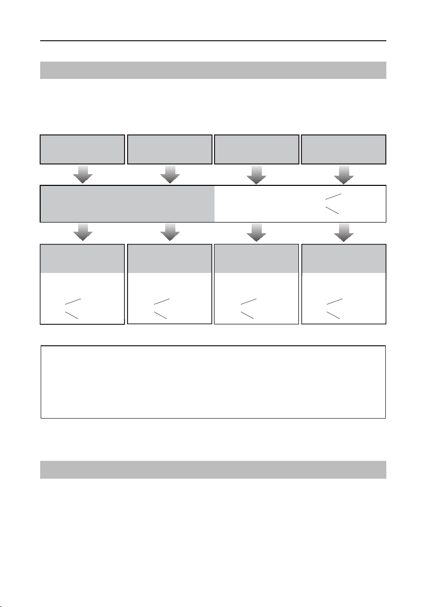
Setting Door Station Address
Total 4 addresses can be congured. It can be modied either before or after installation.
0 is default, to change the setting, please follow the steps:
ID=0,1st door station ID=1,2nd door station ID=2,3rd door station ID=3,4th door station
In standby mode, press
KEY_SET button once
Press KEY_1 button to set
the first door station.
UNLOCK Indicator:OFF
TALK Indicator:OFF
Buzzer
Beep+
Press KEY_2 button to set
the second door station.
UNLOCK Indicator:OFF
TALK Indicator:OFF
Buzzer
Beep,Beep
UNLOCK Indicator:OFF
TALK Indicator:OFF
Press KEY_3 button to set
the third door station.
UNLOCK Indicator:OFF
TALK Indicator:OFF
Buzzer
Beep,Beep,Beep
Buzzer
Beep+, Beep
Press KEY_4 button to set
the fourth door station.
UNLOCK Indicator:OFF
TALK Indicator:OFF
Buzzer
Beep,Beep,Beep,Beep
• If setting mode has not been exited, you can change the address of door station by pressing KEY1~4
freely.
LED_NAME
• The
indicator will always blink until exit out the setting mode.
• If without any operation in 10 seconds, it will exit out setting mode automatically.
• In this step,press
KEY_SET
button four times to exit out the setting mode manually.
Setting Door Station Calling Mode
There are two calling modes for door station.
As apartment system door station, the calling mode is
As villa system door station, the calling mode is
Standard calling
Group calling
mode.
mode.
Please know that the door station work in Standard calling mode by default.
-7-
Page 8
SETUP INSTRUCTIONS
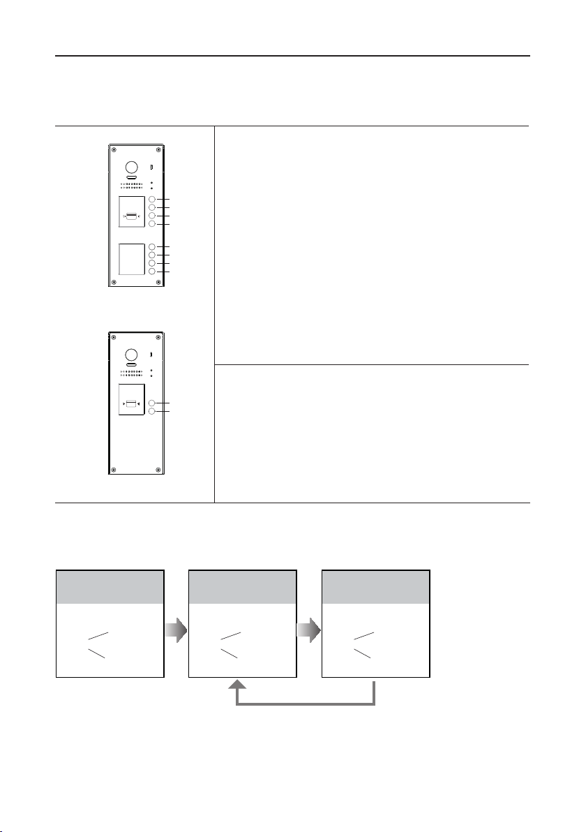
Each call button will respond different addresses when set in different calling mode. Refer to the
followings for more informations.
1.Standard calling mode(Address range 01-08 by
default)
RF CARD
Apartment system
door station
H
G
F
E
D
C
B
A
Call buttonA:
Call buttonB:
Call buttonC:
Call buttonD:
Call buttonE:
Call buttonF:
Call buttonG:
Call buttonH:
call the monitor with address 01 by default.
call the monitor with address 02 by default.
call the monitor with address 03 by default.
call the monitor with address 04 by default.
call the monitor with address 05 by default.
call the monitor with address 06 by default.
call the monitor with address 07 by default.
call the monitor with address 08 by default.
2.Group calling mode
RF CARD
B
A
Call buttonA:
Call all monitors in group address from
00~15.(one of the monitor should be set to 00)
Call buttonB,C,D,E,F,G,H:
Call all monitors in group
address from 16~31. (one of the monitor should be set to
16
Villa system door station
)
* More details about code setting for monitor, please refer to corresponding user manual .
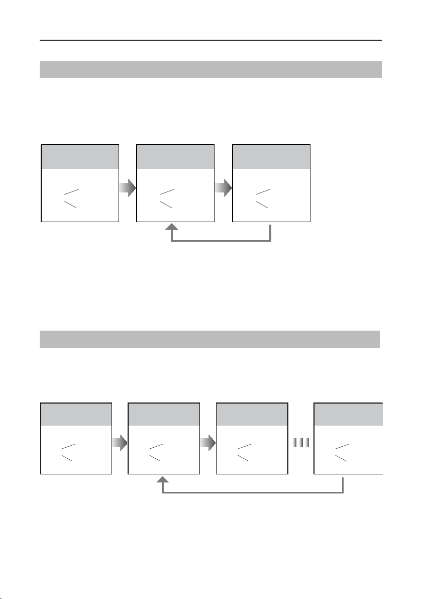
To change this setting, please follow the steps:
In standby mode, press
KEY_SET button twice.
UNLOCK Indicator:OFF
CALL Indicator:ON
Press KEY_1 button to
activate Standard calling
mode for door station.
UNLOCK Indicator:OFF
CALL Indicator:ON
Press KEY_1 button again
to activate Group calling
mode for door station.
UNLOCK Indicator:OFF
CALL Indicator:ON
Buzzer
Beep+, Beep
Buzzer
Beep+
Press KEY_1
Buzzer
Beep, Beep
• If setting mode has not been exited, you can change the calling mode by pressing KEY1 circularly.
LED_NAME
• The
indicator will blink all the time until exit out the setting mode.
• If without any operation in 10 seconds, it will exit out setting mode automatically.
• In this step,press
KEY_SET
button three times to exit out the setting mode manually.
-8-
Page 9
SETUP INSTRUCTIONS
Setting Camera N/P Standard
The standard of the camera can be adjusted at any time, that means the quality of image on
screen can be set to differ.
P standard is default, to change the setting, please follow the steps:
In standby mode, press
KEY_SET button twice.
UNLOCK Indicator:OFF
CALL Indicator:ON
Buzzer
Beep+, Beep
Press KEY_2 button to set the
camera standard to P
standard.
UNLOCK Indicator:OFF
CALL Indicator:ON
Buzzer
Beep+
Press KEY_2 button again
to set the camera standard
to N standard.
UNLOCK Indicator:OFF
CALL Indicator:ON
Buzzer
Press KEY_2
Beep, Beep
• If setting mode has not been exited, you can change the camera standard by pressing KEY2 circularly.
LED_NAME
• The
indicator will blink all the time until exit out the setting mode.
• If without any operation in 10 seconds, it will exit out setting mode automatically.
• In this step,press
KEY_SET
button three times to exit out the setting mode manually.
Setting Prompt Voice
Max. 9-languages voice to select,
Voice 1
is default, to change the setting, please follow the steps:
In standby mode, press
KEY_SET button twice.
UNLOCK Indicator:OFF
CALL Indicator:ON
Buzzer
Beep+, Beep
Press KEY_3 button to set the
prompt voice to Voice 1.
No voice, Voice 1
UNLOCK Indicator:OFF
CALL Indicator:ON
Buzzer
Play the voice 1
Voice 2 ...
and
Press KEY_3 button again
to set the prompt voice to
Voice 2.
UNLOCK Indicator:OFF
CALL Indicator:ON
Buzzer
Play the voice 2
Press KEY_3 button again
and again to set the prompt
voice to No voice.
UNLOCK Indicator:OFF
CALL Indicator:ON
Buzzer
Beep+
Press KEY_3
• If setting mode has not been exited, you can change the prompt voice by pressing KEY3 circularly.
LED_NAME
• The
indicator will blink all the time until exit out the setting mode.
• If without any operation in 10 seconds, it will exit out setting mode automatically.
• The voice can be customized.
-9-
Page 10

SETUP INSTRUCTIONS
Setting Prompt Voice Volume
Total 9 level can be congured. It can be modied either before or after installation.
6 is default, to change the setting, please follow the steps:
In standby mode, press
KEY_SET button twice.
UNLOCK Indicator:OFF
CALL Indicator:ON
Buzzer
Beep+, Beep
Press KEY_4 button to set the
volume level.
UNLOCK Indicator:OFF
CALL Indicator:ON
Buzzer
Play the volume
Press KEY_4
Press KEY_4 button again
and again to set the volume
level you want.
UNLOCK Indicator:OFF
CALL Indicator:ON
Buzzer
Play the volume level 9
• If setting mode has not been exited, you can change the volume level by pressing KEY4 circularly.
LED_NAME
• The
indicator will blink all the time until exit out the setting mode.
• If without any operation in 10 seconds, it will exit out setting mode automatically.
Setting Unlock Mode
There are 2 unlock modes,
Normally opened
Normally opened is default, to change the setting, please follow the steps:
In standby mode, press
KEY_SET button three
times.
UNLOCK Indicator:ON
CALL Indicator:OFF
Press KEY_1 button to set
the unlock mode to
Normally opened.
UNLOCK Indicator:ON
CALL Indicator:OFF
Normally closed
and
Press KEY_1 button again
to set the unlock mode to
Normally closed.
UNLOCK Indicator:ON
CALL Indicator:OFF
.
Buzzer
Beep+, Beep
Buzzer
Beep+
Press KEY_1
Buzzer
Beep, Beep
• If setting mode has not been exited, you can change the unlock mode by pressing KEY1 circularly.
LED_NAME
• The
indicator will blink all the time until exit out the setting mode.
• If without any operation in 10 seconds, it will exit out setting mode automatically.
• In this step,press
KEY_SET
button twice to exit out the setting mode manually.
-10-
Page 11

SETUP INSTRUCTIONS
Setting Unlock Time
By default, the unlock time is 1s, but it can be changed,the setting range is 1s~99s.
Follow the steps:
In standby mode, press
KEY_SET button three
times.
UNLOCK Indicator:ON
CALL Indicator:OFF
Buzzer
Beep+, Beep
Press and hold on KEY_2
button. The time you holding
on is the new unlock time.
UNLOCK Indicator:ON
CALL Indicator:OFF
Buzzer
Beep,Beep......
• When entering time delayed setting, the buzzer sound one time every second.
LED_NAME
• The
indicator will blink all the time until exit out the setting mode.
• If without any operation in 10 seconds, it will exit out setting mode automatically.
• In this step,press
KEY_SET
button twice to exit out the setting mode manually.
Setting Nameplate Illumination Mode
There are 3 illumination modes for nameplate indicator,
Normally on is default, to change the setting, please follow the steps:
In standby mode, press
KEY_SET button three
times.
UNLOCK Indicator:ON
CALL Indicator:OFF
Buzzer
Beep+, Beep
Press KEY_3 button to set
the nameplate illumination
mode to Normally on.
UNLOCK Indicator:ON
CALL Indicator:OFF
Buzzer
Beep+
Normally on,Normally off
Press KEY_3 button again
to set the nameplate illumination mode to Normally off.
UNLOCK Indicator:ON
CALL Indicator:OFF
Buzzer
Beep, Beep
Auto
and
Press KEY_3 button again
and again to set the nameplate
illumination mode to Auto.
UNLOCK Indicator:ON
CALL Indicator:OFF
Buzzer
Beep, Beep,Beep
.
Press KEY_3
• If setting mode has not been exited, you can change the nameplate illumination mode by pressing KEY3
circularly.
LED_NAME
• The
indicator will blink all the time until exit out the setting mode.
• If without any operation in 10 seconds, it will exit out setting mode automatically.
• In this step,press
KEY_SET
button twice to exit out the setting mode manually.
-11-
Page 12

SETUP INSTRUCTIONS
Setting Night View LED Illumination Mode
There are 3 working modes for night view LED indicator,
Normally on,Normally off
and
Auto
.
Auto is default, to change the setting, please follow the steps:
In standby mode, press
KEY_SET button three
times.
UNLOCK Indicator:ON
CALL Indicator:OFF
Buzzer
Beep+, Beep
• If setting mode has not been exited, you can change the night view LED illumination mode by pressing
KEY4 circularly.
LED_NAME
• The
indicator will blink all the time until exit out the setting mode.
• If without any operation in 10 seconds, it will exit out setting mode automatically.
• In this step,press
KEY_SET
Press KEY_4 button to set
the night view LED mode
to Normally on.
UNLOCK Indicator:ON
CALL Indicator:OFF
Buzzer
Beep+
Press KEY_4 button again
to set the night view LED
mode to Normally off.
UNLOCK Indicator:ON
CALL Indicator:OFF
Buzzer
Beep, Beep
Press KEY_4
button twice to exit out the setting mode manually.
Press KEY_4 button again
and again to set the night
view LED mode to Auto.
UNLOCK Indicator:ON
CALL Indicator:OFF
Buzzer
Beep, Beep,Beep
Setting Ring-back Tone
If allow ring-back tone, press the call button to call monitor, a ring-back call tone can be heard
from door station.
There are 3 ring-back call tones,
tone
.
Ringing one time, Ringing continuously
Ringing one time is default, to change the setting, please follow the steps:
No ring-back
and
In standby mode, press
KEY_SET button four
times.
UNLOCK Indicator:ON
CALL Indicator:ON
Buzzer
Beep+, Beep
Press KEY_1 button to set
the ring-back call tone ringing
one time.
UNLOCK Indicator:ON
CALL Indicator:ON
Buzzer
Beep+
Press KEY_1 button again
to set the ring-back call tone
ringing continuously.
UNLOCK Indicator:ON
CALL Indicator:ON
Buzzer
Beep, Beep
Press KEY_1
Press KEY_1 button again
and again to close ring-back
call tone.
UNLOCK Indicator:ON
CALL Indicator:ON
Buzzer
Beep, Beep,Beep
• If setting mode has not been exited, you can change the ring-back tone by pressing KEY1 circularly.
LED_NAME
• The
indicator will blink all the time until exit out the setting mode.
• If without any operation in 10 seconds, it will exit out setting mode automatically.
• In this step,press
KEY_SET
button once to exit out the setting mode manually.
-12-
Page 13

SETUP INSTRUCTIONS
Setting Image Display Mode
Please know that this setting is only effective for monitors which does not support man-
ual operation for pan-tilt.
When the monitor being called
When door station calls monitor,the image will be displayed on screen,there are 3 modes for im-
age displayed,
Alternate switching mode:
Full screen
Zoom mode:
seconds, then switch to
Full screen mode:
screen
Alternate switching mode,Zoom mode
when the monitor being called, switch at regular time(5s) between
Zoom
and
image.
when the monitor being called, the image will be displayed on full screen for 5
Zoom
image.
when the monitor being called, the image will be always displayed on
.
Alternate switching mode is default, to change the setting, please follow the steps:
Full screen mode
and
.
Full
In standby mode, press
KEY_SET button four
times.
UNLOCK Indicator:ON
CALL Indicator:ON
Buzzer
Beep+, Beep
Press KEY_2 button to set
the image display mode
to Cycle switching.
UNLOCK Indicator:ON
CALL Indicator:ON
Buzzer
Beep+
Press KEY_2 button again
to set the image display
mode to Zoom mode.
UNLOCK Indicator:ON
CALL Indicator:ON
Buzzer
Beep, Beep
Press KEY_2
Press KEY_2 button again
and again to set the image
display mode to Full screen.
UNLOCK Indicator:ON
CALL Indicator:ON
Buzzer
Beep, Beep,Beep
• If setting mode has not been exited, you can change the image display mode by pressing KEY2 circularly.
LED_NAME
• The
indicator will blink all the time until exit out the setting mode.
• If without any operation in 10 seconds, it will exit out setting mode automatically.
• In this step,press
KEY_SET
button once to exit out the setting mode manually.
When answering the call
When answering the call, the image switching reminder can be activated or forbidden.
If set to activated mode, the image switching reminder will be different for different image display
mode.
Alternate switching mode:
Zoom mode:
When answering the call, the image will be displayed on
onds, then switch to
When answering the call, image switching reminder is not effective.
full screen
Zoom
image to remind to enter talking status.
for 5 sec-
-13-
Page 14

SETUP INSTRUCTIONS
Full screen mode:
When answering the call, the image will be displayed on
seconds, then switch to
Full screen
to remind to enter talking status.
Zoom
mode for 5
If set to forbidden mode, there is no image switching reminder at any image display mode.
Activated is default, to change the setting, please follow the steps:
In standby mode, press
KEY_SET button four
times.
UNLOCK Indicator:ON
CALL Indicator:ON
Buzzer
Beep+, Beep
• If setting mode has not been exited, you can change the image display mode by pressing KEY3 circularly.
LED_NAME
• The
indicator will blink all the time until exit out the setting mode.
• If without any operation in 10 seconds, it will exit out setting mode automatically.
• In this step,press
KEY_SET
Press KEY_3 button to
activate image switching
when answering the call.
UNLOCK Indicator:ON
CALL Indicator:ON
Buzzer
Beep+
Press KEY_3 button again
to forbid image switching
when answering the call.
UNLOCK Indicator:ON
CALL Indicator:ON
Buzzer
Press KEY_3
Beep, Beep
button once to exit out the setting mode manually.
RAINY_COVER Congure
If can be set the rainy cover mode.
Mounting the rainy cover is default, to change the setting, please follow the steps:
In standby mode, press
KEY_SET button four
times.
UNLOCK Indicator:ON
CALL Indicator:ON
Buzzer
Beep+, Beep
• If setting mode has not been exited, you can change rainy cover mode by pressing KEY4 circularly.
LED_NAME
• The
indicator will blink all the time until exit out the setting mode.
• If without any operation in 10 seconds, it will exit out setting mode automatically.
• In this step,press
KEY_SET
-14-
Press KEY_4 button to set
the rainy cover mode.
UNLOCK Indicator:ON
CALL Indicator:ON
Buzzer
Beep+
Press KEY_4 button again
to set the no rainy cover
mode.
UNLOCK Indicator:ON
CALL Indicator:ON
Buzzer
Press KEY_4
Beep, Beep
button once to exit out the setting mode manually.
Page 15

SETUP INSTRUCTIONS
Registering ID Card
• Up to 320 user cards can be registered by the door station.
• Easy management with LED status and sound hints.
• There are two master cards, one
and one
MASTER CARD DELETE
master cards, the old master cards are invalid automatically.
• Card reading distance is less than 3cm.
• The master cards are necessary when you add or delete user
cards. Please keep it well for future use.
• EM card, 125kHz.
Authorizing master cards:
MASTER CARD ADD
card
card, When registered new
By default,there are two master cards marked
DELETE
,but you should know that the master card can be authorized by users at any time.
MASTER CARD ADD
MASTER CARD
and
That means any two user cards can be authorized to master cards,When registered new master
cards, the old master cards will be invalid automatically.
When power on in 10s,press
and hold on KEY_SET button
for 3s.
UNLOCK Indicator:OFF
CALL Indicator:OFF
Buzzer
Beep+, Beep
LED_NAME
• The
Press KEY_2 button.
UNLOCK Indicator:Blink one time
CALL Indicator:OFF
Buzzer
Beep+
indicator will blink twice per second until exit out the master card authorized mode.
Show the first card to ID
card window, set the card
of MASTER CARD ADD.
UNLOCK Indicator:Blink two times
CALL Indicator:OFF
Buzzer
Beep,Beep
• If without any operation in 10 seconds, it will exit out setting mode automatically.
• It will exit out setting mode automatically after showing these two cards,the UNLOCK&CALL indicator will be
turned off.
Show the second card to ID
card window, set the card of
MASTER CARD DELETE.
UNLOCK Indicator:Blink three times
CALL Indicator:OFF
Buzzer
Beep,Beep,Beep
-15-
Page 16

SETUP INSTRUCTIONS
Switching Access Control:
The access can be controlled by door station or DT-ACC,so it’s available to switch the access
function.
Show the master card of
MASTER CARD DELETE
again to switch as a door
station access control.
UNLOCK Indicator:OFF
Show the master card of
MASTER CARD ADD to ID
card window in standby.
UNLOCK Indicator:OFF
CALL Indicator:ON
Buzzer
Beep+, Beep
Show the master card of
MASTER CARD DELETE
to ID card window.
UNLOCK Indicator:ON
CALL Indicator:ON
Buzzer
Beep+, Beep
CALL Indicator:OFF
Buzzer
Beep+
Show the master card of
MASTER CARD DELETE
again to switch to DT-ACC
controlled.
UNLOCK Indicator:OFF
CALL Indicator:OFF
Buzzer
Beep,Beep
• If without any operation in 10 seconds, it will exit out setting mode automatically.
• If current access is controlled by door station, next access switching setting is controlled by DT-ACC.
Adding User Cards:
Show the master card of
MASTER CARD ADD to ID
card window in standby.
UNLOCK Indicator:OFF
CALL Indicator:ON
Buzzer
Beep+, Beep
• If without any operation in 10 seconds, it will exit out setting mode automatically.
• To add user card, the access must be controlled by door station.
-16-
Show user cards to be
added in sequence.
UNLOCK Indicator:OFF
CALL Indicator:Blink one time
Buzzer
Beep+
Show the master card of
MASTER CARD ADD again
to exit.
UNLOCK Indicator:OFF
CALL Indicator:OFF
Buzzer
Beep, Beep+
Page 17

SETUP INSTRUCTIONS
Deleting User Cards:
Show the master card of
MASTER CARD DELETE to
ID card window in standby.
UNLOCK Indicator:ON
CALL Indicator:OFF
Buzzer
Beep+, Beep
Show user cards to be
deleted in sequence.
UNLOCK Indicator:Blink one time
CALL Indicator:OFF
Buzzer
Beep+
Show the master card of
MASTER CARD DELETE
again to exit.
UNLOCK Indicator:OFF
CALL Indicator:OFF
Buzzer
Beep, Beep+
• .If without any operation in 10 seconds, it will exit out setting mode automatically.
• To add user card, the access must be controlled by door station.
Initializing Access (delete all user cards):
Show the master card of
MASTER CARD DELETE to
ID card window in standby.
UNLOCK Indicator:ON
CALL Indicator:OFF
Buzzer
Beep+, Beep
Show the master card of
MASTER CARD ADD to ID
card window.
UNLOCK Indicator:ON
CALL Indicator:ON
Buzzer
Beep+, Beep
• If without any operation in 10 seconds, it will exit out setting mode automatically.
• To add user card, the access must be controlled by door station.
• At step3, the UNLOCK & CALL indicator will blink all time until formatting is nished.
• When formatting is nished, UNLOCK & CALL indicator will be turned off and sound “ Beep+ ”, and exit out
setting mode automatically.
Show the master card of
MASTER CARD ADD again,
format is activated.
UNLOCK Indicator:Blink for some time
CALL Indicator:Blink for some time
Buzzer
Beep
Restore To Default
The restore to default function allows the user to recover the settings to factory setting.
When power on in 10s,press
and hold on KEY_SET button
for 3s.
UNLOCK Indicator:OFF
CALL Indicator:ON
Buzzer
Beep+, Beep
LED_NAME
• The
indicator will blink twice per second until exit out the restore to default mode.
• If without any operation in 10 seconds, it will exit out setting mode automatically.
• When restoring is finished, UNLOCK & CALL indicator will be turned off, and exit out setting mode
automatically.
Press KEY_3 button.
UNLOCK Indicator:ON
CALL Indicator:ON
Buzzer
Beep+
-17-
Page 18

WIRING
Connecting Electric Lock(NOT RECOMMENDED). See Next
page
Note: NOT RECOMMENDED unless the door lock is less than 250mA. Please see Next page
for HOW TO HOOK UP A DOOR RELEASE.
Door Lock Controlled with Internal Power
1.Electronic lock of Power-on-to-unlock
type should be used.
2.The door lock is limited to 12V, and hold-
ing current must be less than 250mA.
3.The jumper should be placed on position
2 and 3 before connecting.
4.The door lock control is not timed from
Exit Button(EB).
5.The
Unlock Mode
must be set to 0 (by
default).
Door Lock Controlled with Dry Contact
1.The external power supply must be used
according to the lock.
2.The inside relay contact is restricted to
230Vac 1A or 24Vdc 1A.
3.The jumper must be taken off before
connecting.
4.Setup the
Unlock Mode
different lock types.
according to
1 2 3
Jumper position on 2&3
L1 L2 PL S+ S-
*
EB
1 2 3
Take off the jumper
L1 L2 PL S+ S-
LOCK
• Power-on-to-unlock type:Unlock
Mode=0 (by default)
• Power-off-to-unlock type:Unlock
Mode=1
* DT-RLC relay actuator is needed for 2nd lock connection.
-18-
POWER
SUPPLY
LOCK
Page 19

WIRING
How to hook up a door release
Door Station
DT608
L1 L2 PL S+ S-
X XINX X
A/C or D/C
Power Supply
+ -
OUT
Model: DS-ERL
Note: Relay is NOT SENSITIVE to POLARITY.
For Magnetic Locks you will need a ELK-1 Relay.
Door Station
DT608
Power
Supply
L1 L2 PL S+ S-
+ -
-
+
- + N/O COM N/C
Magnetic Lock
ELK1 Relay
For A/C or D/C door
releases HINTS.
Match the door release
Input Voltage to power
source.
Power Door
Release
A/C = A/C
D/C = D/C
12vDC = 12vDC
24vDC = 24vDC
16vA/C = ∞16vA/C
∞
S
T
R
I
K
E
Power Supply can be A/C or
D/C as long as it matches the
needs of the magnetic lock.
By hooking up the ELK1 to the
door release this saves the
outdoor station from being
damaged which is NOT
covered by the warranty!
The reason for this is that all
Magnetic Locks have more
than 200mA and the panel
relay Max is 200m
A.
Note: Bus (L1, L2) to DT-DPS or DBC4A1 if you
have more than 1 door station.
-19-
Page 20

WIRING
Connecting Multi Door Stations
st
door station
1
ID=0
RF CARD RF CARD RF CARD RF CARD
L1 L2 PL S+ S- L1 L2 PL S+ S- L1 L2 PL S+ S- L1 L2 PL S+ S-
2nd door station
ID=1
Impedance
switch
OFF
ON
3rd door station
A B C D
DBC4A1
ID=2
-
+
4th door station
ID=3
DPSDR-30-24
MonitorsMonitorsMonitors
Code=0,DIP6=offCode=30,DIP6=offCode=31,DIP6=on
• Max.4 door stations can be connected to the system.
• Ensure to set the correct address for each door station, Refer to Page 7 for more details
about the address setting of door stations.
-20-
Page 21

WIRING
Eight Apartments Connection
Impedance
switch
OFF
ON
A B C D
DBC4A1
Impedance
switch
OFF
ON
A B C D
DBC4A1
-
+
DPSDR-30-24
RF CARD
-21-
Page 22

APPENDIX
Precautions
• Please clean the unit with soft cotton cloth, don't use the organic impregnant or chemical
clean agent. If necessary, please use a little pure water or dilute soap water to clean the dust.
• The unit is weather resistant. However do not spray high pressure water on access control
keypad directly. Excessive moisture may cause problems with the unit.
• You must use the right adaptor which is supplied by the manufacture or approved by the
manufacture.
• Pay attention to the high voltage inside the products, please refer service only to a trained
and qualied professional.
Specication
●Power Supply : DC 24V;
●Power Consumption: Standby 1.2W; Working status 4.8W;
●Fish Camera: Color CMOS, 2.0 Mega pixel 1/2.7’’
● fisheye camera,170° wide angle(DT608);
●1050 Camera: Color CMOS, 520TVL , 1/4’’ camera,
● 1050 wide angle (DT608C)
;
●Lock Power supply: 12Vdc, 250mA(Internal Power);
●Unlock time: 1~99s(Default 5s);
●Number of relay circuits: 2 (the second lock need external
● device to support);
●Working temperature: -20ºC ~ +55ºC;
●Wiring: 2 wires,non-polarity;
●Protection: IP45
;
●Dimension: 11.06(H)x4.33(W)x1.73(D) in.
-22-
Page 23

APPENDIX
Cables and Requirments
The maximum distance of the wiring is limited in the DT system. Using different cables may also
affect the maximum distance which the system can reach.
Basic IN-OUT Wiring Mode
When Monitor quantity < 20
B
Cable Usage A B
Twisted cable 2x0.00116 sq.in 196ft 196ft
Twisted cable 2x0.00155 sq.in 262ft 262ft
When Monitor quantity > 20
-
+
DPSDR-30-24
Cable Usage A B
Twisted cable 2x0.00155 sq.in 229ft 98ft
A
Twisted cable 2x0.00233 sq.in 229ft 164ft
Note:
1. The thicker the copper wire is, the longer distances will be. Best wire to use is 18 Gaugetwisted, while Cat 5 or 6 are not recommended.
RF CARD
2. In this basic IN-OUT wiring without distributor
DBC4A1, should connect Max 5 monitors, see
next page to connect more monitors with distributor DBC4A1.
-23-
Page 24

APPENDIX
Star Topology Wiring Mode With DBC4A1
2
DBC4A1
B
2
-
+
DPSDR-30-24
When Monitor quantity < 20
C
Cable Usage A B C
Twisted cable 2x0.00116 sq.in 196ft 196ft 98ft
A
Twisted cable 2x0.00155 sq.in 262ft 262ft 131ft
When Monitor quantity > 20
Cable Usage A B C
Twisted cable 2x0.00155 sq.in 229ft 98ft 65ft
RF CARD
Twisted cable 2x0.00233 sq.in 229ft 164ft 98ft
Note: The thicker the copper wire is, the longer distances will be. Best wire to use is 18 Gauge twisted,
while Cat 5 or 6 are not recommended.
-24-
Page 25

Page 26

Page 27

Page 28

DT-ENG-608-V1
The design and specifications can be changed without notice to the user. Right to interpret and copyright of this
manual are preserved.
 Loading...