

Page 1
2 -Wire Intercom System
DT603F Series User Manual
DT603DFDT603F
DT-ENG-603F-V1 20141108
Page 2

-2-
Page 3

CONTENTS
1.Parts and Functions............................................................................................. 1
2.Terminal Descriptions .......................................................................................... 1
3.Specications ...................................................................................................... 2
4.Mounting .............................................................................................................. 2
4.1 Mounting ....................................................................................................... 2
4.2 Placing Name Label ...................................................................................... 3
5.System Wiring and Connections ......................................................................... 3
5.1 Basic Connection........................................................................................... 3
5.2 Electric Lock Connection ............................................................................... 4
5.2.1 Door Lock Controlled with Internal Power ............................................. 4
5.2.2 Door Lock Controlled with Dry Contact ................................................. 4
5.2.3 Unlock parameter setting(set on monitor) ............................................. 5
5.3 Multi Doorstations Connection....................................................................... 5
5.4 Multi Monitors Connection ............................................................................. 6
5.4.1 Basic IN-OUT Wiring Mode ................................................................. 6
5.4.2 With DBC-4S Wiring Mode .................................................................. 7
6.Setup ................................................................................................................... 8
6.1
ID of Doorstation Settings
6.2
Unlock Time Settings
6.3
Ringtone Modes Settings
7.Cables Requirements .......................................................................................... 11
......................................................................... 8
................................................................................. 9
.......................................................................... 10
Page 4
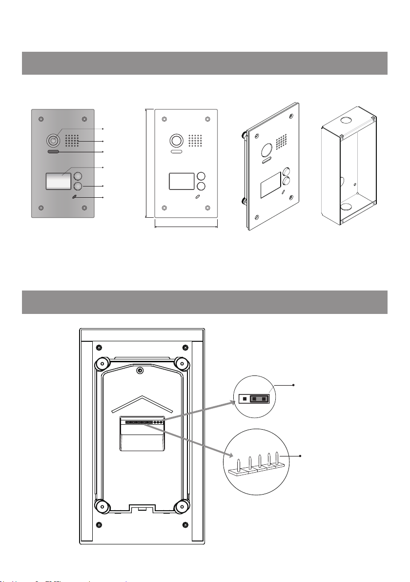
1.Parts and Functions
Camera Lens
Speaker
Night Light
Nameplate
Call Button
Microphone
188 mm
2.Terminal Descriptions
110 mm
1 2 3
BUS
PL
Side View
S-
S+
Mounting box
JP/LK
Main Connect Port
-1-
Page 5
JP/LK:
•
•
Lock control jumper, to select the lock type(see 5.2.1 , 5.2.2).
Main Connect Port:
To connect the bus line and the electronic locks.
•BUS: Connect to the bus line, no polarity.
• PL: External lock power input, connect to the power positive(power +).
• S+: Lock power(+) output.
• S-: Lock power(-) output, connect to the power(-) input of locks(only when using the camera to
power the locks, if using the external power supply for the locks, the S- will not be connected).
3.Specications
•Power Supply : DC 24V;
•Lock Power supply: 12Vdc, 300mA(Internal Power);
•Power Consumtion: Standby 33mA; Working status 110mA;
•Camera: Color ARS; 650 TV Lines;
•Unlocking time: 1~30s(Default 1s);
•Working temperature: -15ºC ~ 55ºC;
•Dimension: 188(H)×110(W)×39(D)mm.
4.Mounting
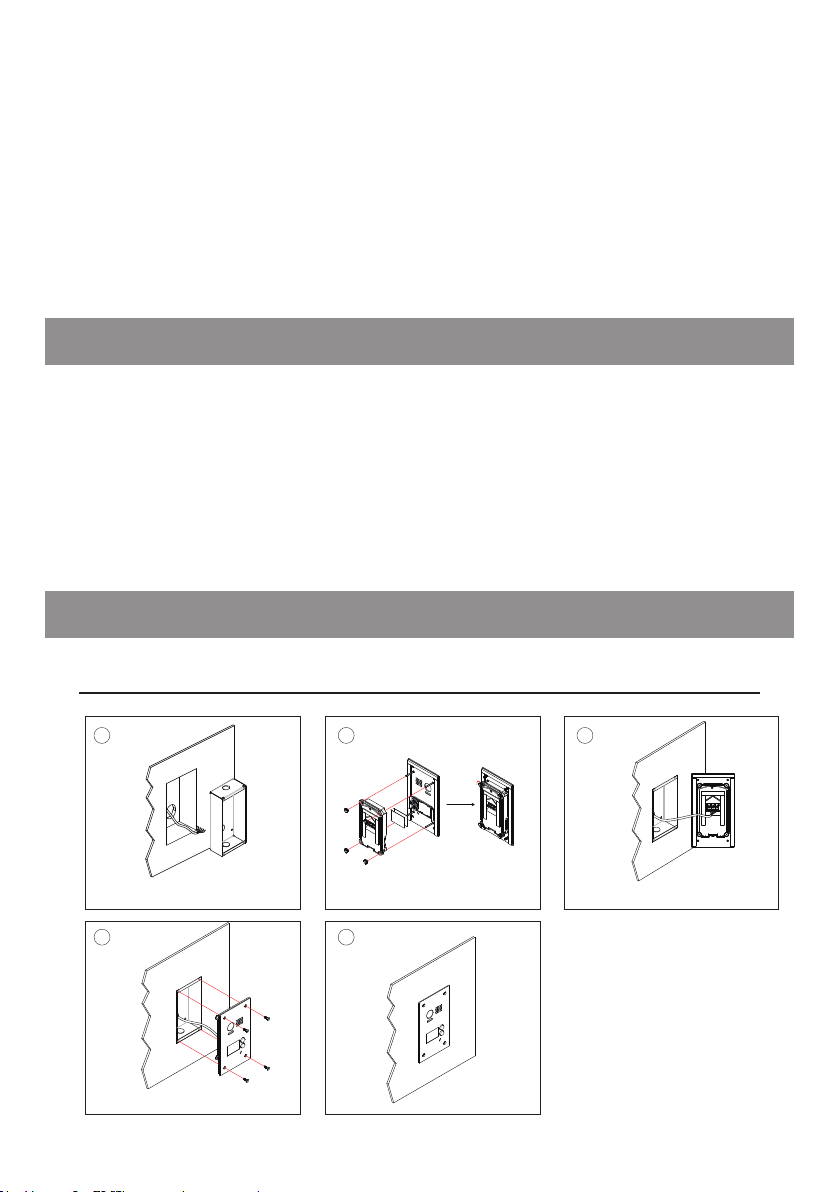
4.1 Mounting
1 2
Drill a hole in the wall to match the size of the
mounting box and attach to the wall.
Attach the panel to the mounting box and
use screws supplied to fix the panel
3
Connect the cable correctly
54
-2-
Page 6

4.2 Placing Name Label
Switch
Move the plastic cover away to open the transparent name label cover, insert a
name paper, then put the plastic cover back to the panel.
Name label.
STEP 1
Unscrew the screws.
STEP 2
Replace name label.
5.System Wiring and Connections
5.1 Basic Connection
AC~
PC6
DIPS
1 2 3
Doorbell Button
ON
BUS(IM) BUS(DS)
L1 L2 PL S+ S-
-
+
-3-
Page 7

5.2 Electric Lock Connection
5.2.1 Door Lock Controlled with Internal Power
Note:
1. Electronic lock of Power-on-to-unlock
type should be used.
2. The door lock is limited to 12V, and
holding current must be less than 250mA.
3. The door lock control is not timed from
Exit Button(EB).
4. The
Unlock Mode
Parameter of Monitor
must be set to 0 (by default).
5. When it connect Electronic lock, the
jumper position in 2-3.
6. When it connect E-magnetic lock, the
jumper position in 1-2.
1 2 3
1 2 3
*
connect E-magnetic lock, the jumper position in 1-2.
connect Electronic lock, the jumper position in 2-3.
PL S+S-
BUS
EB
LOCK
5.2.2 Door Lock Controlled with Dry Contact
Note:
1. The external power supply must be
used according to the lock.
2. The jumper must be taken off
before connecting.
3. Setup the
Unlock Mode
of Monitor
for different lock types.
• Power-on-to-unlock type:Unlock
Mode=0 (by default)
• Power-off-to-unlock type:Unlock
Mode=1
-4-
Take off the Jumper
BUS PL S+S-
POWER
SUPPLY
LOCK
Page 8

5.2.3 Unlock parameter setting(set on monitor)
About
Local Address 00.00
Video Standard
System Verson 00.01.00
Display Driver 1.0
Front 1.0
UI 1.0
AUTO
123
INSTALLER SETUP
_
1.Touch icon on
main menu page.
2.Touch
button and hold for 2s.
UNLOCK
3.A digital keypad will
be shown.
Note:
1.must connect DT603F/603DF correctly before setting.
2.the parameter will be saved in DT603F/603DF automatically,so you need only set on one monitor.
3.Here we take DT47M(the monitor) for example, please refer to the corresponding user manual.
5.3 Multi Doorstations Connection
(Device Address:3) (Device Address:2) (Device Address:1) (Device Address:0)
L1 L2 PL S+ S- L1 L2 PL S+ S- L1 L2 PL S+ S- L1 L2 PL S+ S-
1# Camera2# Camera3# Camera4# Camera
AC~
100~240VAC
OFF
ON
Impedance
switch
A B C D
DBC4A
PC6
BUS(IM) BUS(DS)
-5-
Page 9

5.4 Multi Monitors Connection
5.4.1 Basic IN-OUT Wiring Mode
Code=30Code=31
AC~
Code=0
100~240VAC
PC6
BUS(IM) BUS(DS)
(Device Address:0)
NOTE:Here we take DT47M(the monitor) for example.
-6-
Page 10

5.4.2 With DBC4A Wiring Mode
Code=31
Code=29
Code=3
Code=1
Code=30
Code=28
Code=2
Code=0
AC~
100~240VAC
Impedance
switch
Impedance
switch
OFF ON
A B C D
OFF ON
A B C D
DBC4A
DBC4A
PC6
BUS(IM) BUS(DS)
NOTE:Here we take DT47M(the monitor) for example.
(Device Address:0)
-7-
Page 11

6. Setup
B
A
6.1 ID of Doorstation Settings
The ID of doorstation can be set to ID0/ID1/ID2/ID3.The default is ID0.
A
Note:Monitors response button A must set the user code from 0
to 15.and button B set the user code from 16 to 31.
1)Power-on within 5 seconds;
2)Press and hold "B" button for 3
seconds, it will enter the setting
state of prepare.
background indicator Buzzer
(ash)
beep+,beep
Press and hold "A" and "B"
button for 3 seconds at the same
time, it will enter the state of ID
setting.
background indicator Buzzer
(off)
beep+,
Followed by pressing the "B"
button, each time you press "B"
button to replace the ID;
Note:The ID will cycle between
ID0 ID1 ID2 ID3.
background indicator Buzzer
beep one
beep twice
beep 3 times
beep 4 times
ID1:
ID2:
ID3:
(ash one)ID0:
(ash twice)
(ash 3 times)
(ash 4 times)
-8-
Page 12

6.2 Unlock Time Settings
The unlock time can be set to 1~30 seconds. The default is 1s.
1)Power-on within 5 seconds;
2)Press and hold "B" button for 3
seconds, it will enter the setting
state of prepare.
background indicator Buzzer
(ash)
beep+,beep
Press and hold "A" button for 3
seconds, it will enter the state of
unlock time setting.
background indicator Buzzer
(off)
beep+,
At this time press and hold "B"
button,timing starts; release "B"
button to end the timing. The
time of press and hold "B" button
equal to unlock time.(Timing Unit:
1s)
background indicator Buzzer
(ash once per second)
beep once
per second
Note:During timing, the background indicator ashes once per second, tone beeps once per second. Less
than one second by one second calculation.
-9-
Page 13

6.3 Ringtone Modes Settings
The system supports three ringtone modes: [A]one ringtone, [B]continuous
ringtone, [C]forbid ringtone. The default is one ringtone.
1)Power-on within 5 seconds;
2)Press and hold "B" button for 3
seconds, it will enter the setting
state of prepare.
background indicator Buzzer
(ash)
beep+,beep
Press and hold "B" button for 3
seconds at the same time, it will
enter the state of ringtone modes
setting.
background indicator Buzzer
(off)
beep+,
Followed by pressing the "B"
button,each time you press "B" to
replace the ringtone mode;
Note:The ringtone mode will cycle
between
background indicator Buzzer
[A]:
[B]:
[C]:
[A]
(ash one)
(ash twice)
(ash 3 times)
[B]
beep one
beep twice
beep 3 times
[C].
-10-
Page 14

7.Cables Requirements
The maximum distance of the wiring is limited in the DT system. Using different cables may also affect the
maximum distance which the system can reach.
The farest monitor
monitor
with two or four monitors
monitor
When Monitor quantity < 20
Cable Usage A B C
2
Twisted cable 2x0.75 mm
Twisted cable 2x1 mm
60 60 30
2
80 80 40
When Monitor quantity > 20
Cable Usage A B C
2
Twisted cable 2x1 mm
Twisted cable 2x1.5 mm
Note:If the monitor has been specied the distance,refer to the
parameter.
70 30 20
2
70 50 30
monitor
C
DBC4A
B
AC~
100~240VAC
PC6
BUS(IM) BUS(DS)
A
-11-
Page 15

-12-
Page 16

The design and specications can be changed without notice to the user. Right to interpret
and copyright of this manual are preserved.
 Loading...