

Page 1
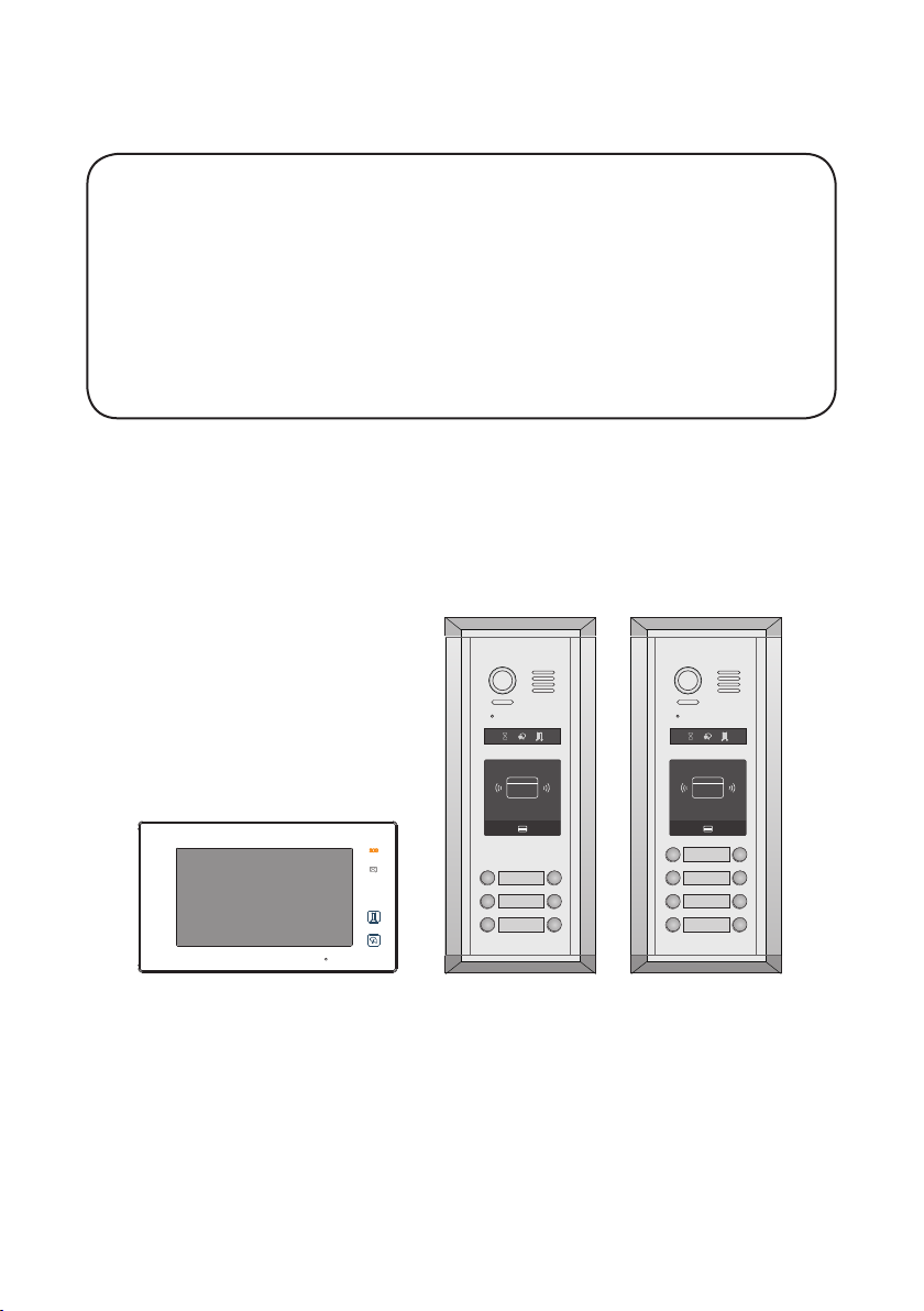
2 WIRE INTERCOM SYSTEM
DK4761 & DK4781
Quick Guide
RF CARDRF CARD
Please read this manual carefully before using the product you purchase, and keep it well for future use.We reserve the right to
modify the specication in this manual at any time without notice.
Page 2

1. Product Lists Of Kits
Kit DK4761 consists of
1* Outdoor Station- DMR11S/ID/D6
1* Surface Box- RH-MR11
6* Indoor Units- DT47MG-W
2* Four Outputs Controller- DT-DBC4A1
1* Power Supply with UL approved- DR-30-24
1* Power Separator- DT-DPS
1* DIN Rail
1* Relay- DS-ERL
1* AWG18 Power Cable
2* Management Cards- Add Card & Delete Card
12* Proximity Cards
Kit DK4781 consists of
1* Outdoor Station- DMR11S/ID/D8
1* Surface Box- RH-MR11
8* Indoor Units- DT47MG-W
2* Four Outputs Controller- DT-DBC4A1
1* Power Supply with UL approved- DR-30-24
1* Power Separator- DT-DPS
1* DIN Rail
1* Relay- DS-ERL
1* AWG18 Power Cable
2* Management Cards- Add Card & Delete Card
16* Proximity Cards
:
:
-1-
Page 3
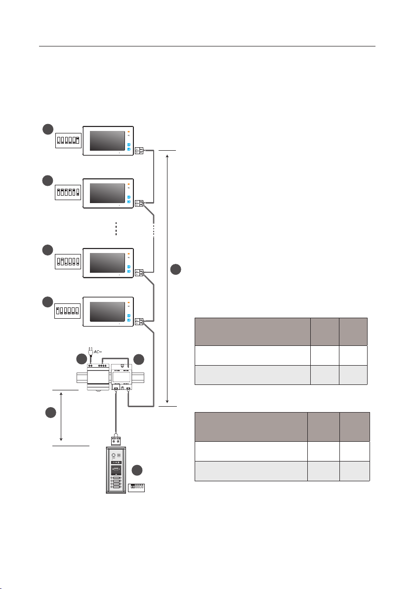
2. System Connection
In-out wiring without any distributor
5
ON
1 2 3 4 5 6
Code=32, DIP-6=on
4
ON
1 2 3 4 5 6
Code=31, DIP-6=off
4
ON
1 2 3 4 5 6
Code=2, DIP-6=off
4
ON
1 2 3 4 5 6
Code=1, DIP-6=off
A
[1]: Door Station, when there is only one Door Station,
the DIP bit-1 and bit-2 should be set to 00.
[2]: Power Supply(DR-30-24), MUST be installed side
by side with the DPS unit.
[3]: Power Separator, MUST be installed side by side
with the DR-30-24 unit.
[4]: Monitor, each one with a unique User Code (Max.32
Monitors), the bit-6 of the DIP should be set to 0 (off) if
the Monitor is not at the end of the bus line.
[5]: Monitor, the bit-6 of the DIP should be set to 1 (on)
B
if the Monitor is connected at the and of the bus line.
When Monitor quantity < 20
Cable Usage A B
3
-
+
2
DPSDR-30-24
Twisted cable 2x0.00116 sq.in 196ft 196ft
Twisted cable 2x0.00155 sq.in 262ft 262ft
When Monitor quantity > 20
Cable Usage A B
-2-
Twisted cable 2x0.00155 sq.in 229ft 98ft
RF CARD
ID=00
1 2 3 4 5 6
ON
1
Twisted cable 2x0.00233 sq.in 229ft 164ft
Note: The thicker the copper wire is, the longer distances
will be. Best wire to use is 18 Gauge twisted, while Cat 5
or 6 are not recommended.
Page 4
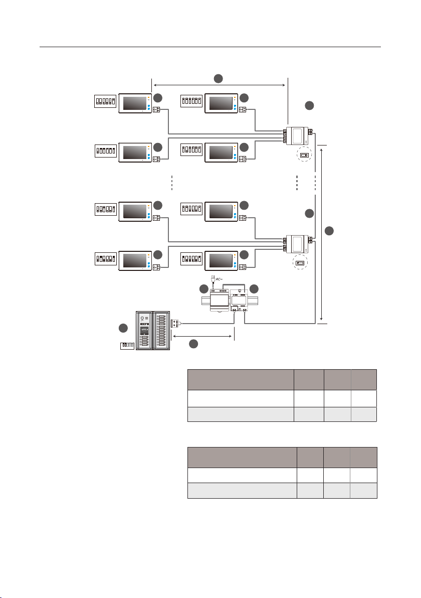
Star wiring with 4 output distributor DBC4A1
ON
1 2 3 4 5 6
Code=32, DIP-6=on
ON
1 2 3 4 5 6
Code=30, DIP-6=on
ON
4 4
1 2 3 4 5 6
Code=31, DIP-6=on
ON
4 4
1 2 3 4 5 6
Code=29, DIP-6=on
C
6
DBC4A1
A B C D
Impedance
OFF ON
switch
ON
1 2 3 4 5 6
Code=4, DIP-6=on
ON
1 2 3 4 5 6
Code=2, DIP-6=on
1
ID=00
1 2 3 4 5 6
ON
4 4
4 4
RF CARD
[1]: Door Station, when there is only one Door
Station, the DIP bit-1 and bit-2 should be set
to 00.
[2]: Power Supply(DR-30-24), MUST be
installed side by side with DPS unit.
[3]: Power Separator, MUST be installed side
by side with the DR-30-24 unit.
[4]: Monitor, each one with a unique User
Code, note that all the bit-6 of the DIP should
be set to 1 (on) in this case.(Max.32 Monitors)
[5]: 4 output distributor DBC4A1,Impedance
switch of all DBC4A1 should be set to OFF,
except the last DBC4A should be set to ON.
(When there is only 1 DBC4A1, should set to
ON).
ON
1 2 3 4 5 6
Code=3, DIP-6=on
5
B
DBC4A1
ON
1 2 3 4 5 6
Code=1, DIP-6=on
3
-
+
2
DPSDR-30-24
Impedance
switch
A B C D
OFF ON
A
When Monitor quantity < 20
Cable Usage A B C
Twisted cable 2x0.00116 sq.in 196ft 196ft 98ft
Twisted cable 2x0.00155 sq.in 262ft 262ft 131ft
When Monitor quantity > 20
Cable Usage A B C
Twisted cable 2x0.00155 sq.in 229ft 98ft 65ft
Twisted cable 2x0.00233 sq.in 229ft 164ft 98ft
Note: The thicker the copper wire is, the longer distances will
be. Best wire to use is 18 Guage twisted, while Cat 5 or 6 are not
recommended.
-3-
Page 5
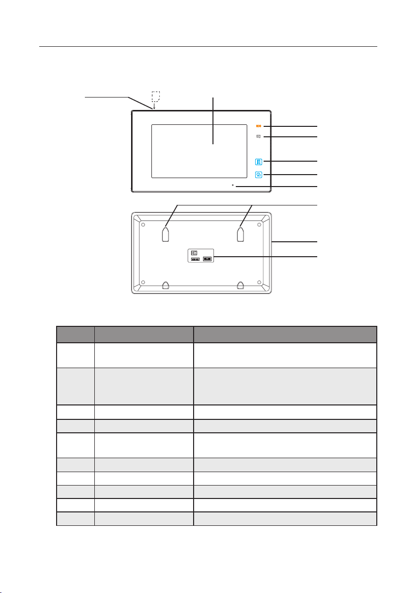
3. Parts and Functions
[7]
SD card
[1]
ON DIP
1 2 3 4 5 6
Key functions
NO. Item Description
[1] Digital LCD touch screen
See the next page for details
Display the visitors' image
[2]
[3]
[4]
[5]
[6]
[8]
[9]
[10]
-4-
[2] Emergency button
Press it & hold for 3s to send SOS message to mo-
bile phone,the function is supported by GSM unit.
[3] Message indicator Light up when the monitor has missed call
[4] Unlock button Press to release the door
[5] Talk/Mon button
Press to communicate hands free with visitor
Press to view the outdoor condition in standby mode
[6] Microphone Transmit audio from one station to other stations
[7] SD card slot Use to insert micro-SD card
[8] Mounting hook Use to hang up the monitor
[9] Speaker Send out sounds of ring tones,audios and alarms
[10] Connection port Bus terminal
Page 6
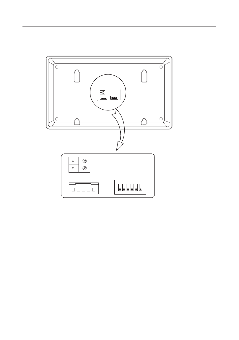
Terminal description
SW+
SW-
RING
L1
L2
NC
GND
ON DIP
1 2 3 4 5 6
DIP Switches
ON DIP
1 2 3 4 5 6
L1,L2:
Bus line terminal.
SW+,SW-:
Ring,GND:
NC:
DIP switches:
Bit1~Bit5:
•
Bit6:
•
Otherwise, set to
Extra door bell call button connection port.
Extra buzzer connection port.
Undened.
Total 6 bits can be congured.
User Code setting.
Set to ON if the monitor is at the end of the line or works with DBC4A.
OFF
.
-5-
Page 7
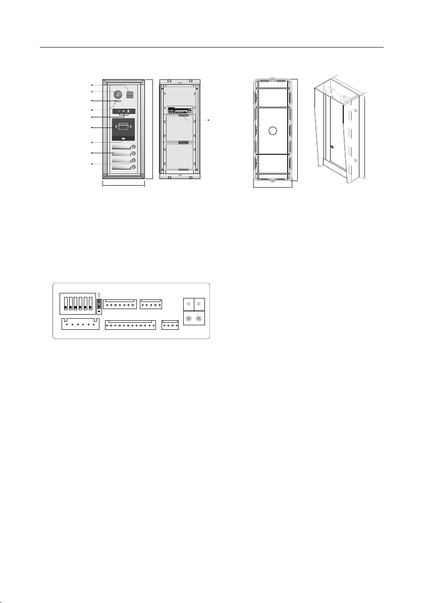
Speaker
Camera Lens
Night View LED
Microphone
Status Indicator
ID Card Window
LED Indicator
Nameplate
Call button
A B
RF CARD
12.13 inch
5.04 inch
ON DIP
1 2 3 4 5 6
L1L2
Connection
port
10.91 inch
12.28 inch
4.84 inch
4.17 inch
Mounting box for
flush mounted
Rainy cover for
surface mounted
Note:Key A and key B will not be seen on the panel,they are cryptic.About activating key
A and key B, please refer to Part 5.
4. Terminal Description For Outdoor Station
ON DIP
SET
1 2 3 4 5 6
EB+
CN-LK
• +12V: 12VDC power output.
• LK-: Power ground. See page 13 for hook-up with DS-ERL included in kit.
• LK+: Common contact of the relay.
• NO.: Normally open contact of the relay
• EB+: Exit button positive connection port.
• EB-: Exit button negative connection port.
• JP-LK: For electronic lock safety type setting(refer to door lock connections).
• SET : DIP switches for system configurations. By default, DIP5 is on, that
means the unlocking time is 5 seconds.
• CN/KMB: Call button module connection port.
• CN/T-COIL: Reserved.
• CN/FUN: Touch sensor keypad module or TFT display module connection
port.
• CN/WGN: Card reader module connection port.
• Bus(L1,L2): Non-polarity bus line,connect to power supply.
JP-LK
+12V
LK-
LK+NOEB-
GND
12V
CLK
DAT
STRC2C1
CN/KMB CN/T-COIL
GND
GND
GND
RST
5DA
RX3
TX3
5CL
INT
CN/FUN CN/WGN
CTR
GND
GND
VIO
POW
WG0
WG1
GND
12V
RX1
TX1
12V
L1 L2
-6-
Page 8
ON
ON
1 2 3 4 5 6
1 2 3 4 5 6
ON
ON
1 2 3 4 5 6
1 2 3 4 5 6
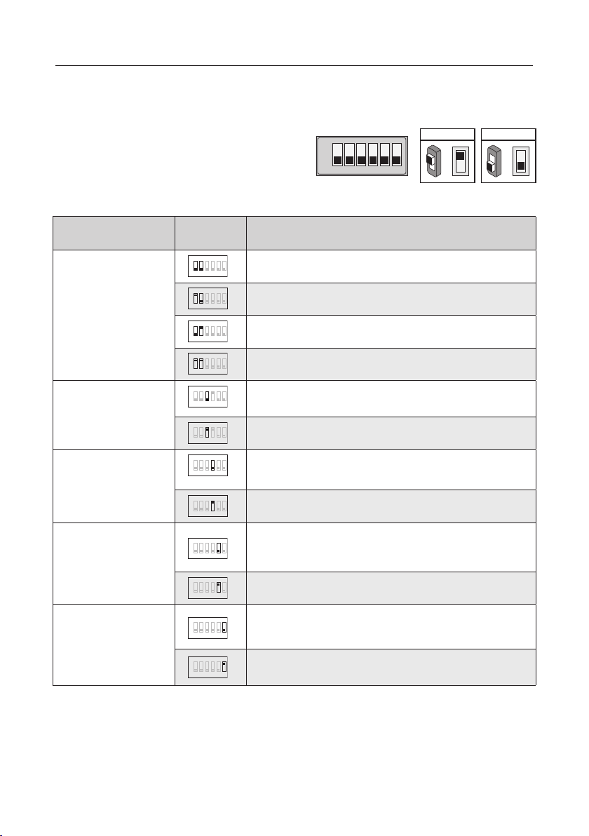
5. DIP Switches Settings Of Outdoor Station
Totally 6 bits can be congured by dip-switch. All
switches can be modified either before or after
installation, please restarting the power whenever
the switches have been modied.
ON
1 2 3 4 5 6
Bit denition Bit state Function Descriptions
Bit-1 and Bit-2
(door station ID setting)
Bit-3
(single or double row
button setting)
Bit-4
(button code select)
ON
1 2 3 4 5 6
1 2 3 4 5 6
1 2 3 4 5 6
ON
ON
1 2 3 4 5 6
ON
ON
1 2 3 4 5 6
ON
1 2 3 4 5 6
Default setting, ID = 0, setting for the rst door station
ID = 1, setting for the second door station
ID = 2, setting for the third door station
ID = 3, setting for the fourth door station
Default setting ,set "OFF " when using a double row button door
station
Set "ON" when using a single row button door station
Default setting, set "OFF " when using the default codes of the
button
Set " ON " when using the programmed codes of the button.
Unlocking time = 1second. (can be changed by door station or
Bit-5
1 2 3 4 5 6
software)
(unlock time quick setting)
1 2 3 4 5 6
Default setting, unlocking time = 5 seconds.
ON
ON(1)
=
OFF(0)
ON
=
Bit-6
(cryptic key setting)
ON
Default setting, normally key A and key B is not useful(about the
position of key A and key B,please refer to part 2)
ON
Activating the key A and key B is allowed.
-7-
Page 9
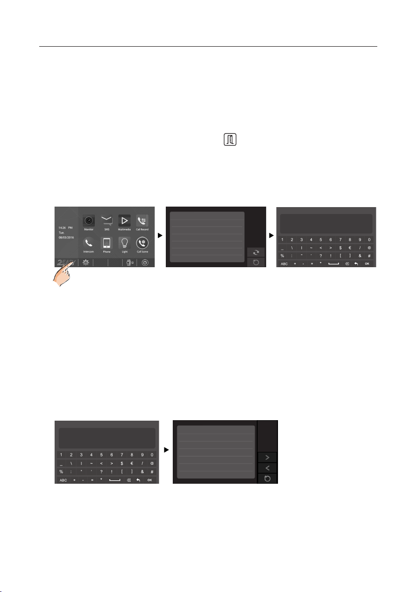
6. Indoor Unit Parameter Setting
How to enter the installation setting page
• On main menu page, touch [Logo] icon to enter About page.
• When the screen stay in About page,press UNLOCK button on front panel and
hold for 2 seconds.
• A keypad is shown.
Refer to the followings:
00:10 DS-1
About
Local Address 00.00
Video Standard
System Verson 00.01.00
Display Driver 1.0
Font 1.0
UI 1.0
AUTO
How to know the machine code
Input the key “? and ok” to open Help instructions menu.
Refer to the followings:
_
INSTALLER SETUP
? + OK: Help Menu
@ + OK: Address Setting Menu
123
Help 01/04
2412:Reset to Default Setting
2499:Format Memory
2810:MCU Code Update
2811:TFT,UI Code Update
2812:Consumer Tune Update
2813:Format SD Card
INSTALLER SETUP
_
? + OK: Help Menu
@ + OK: Address Setting Menu
123
-8-
Page 10
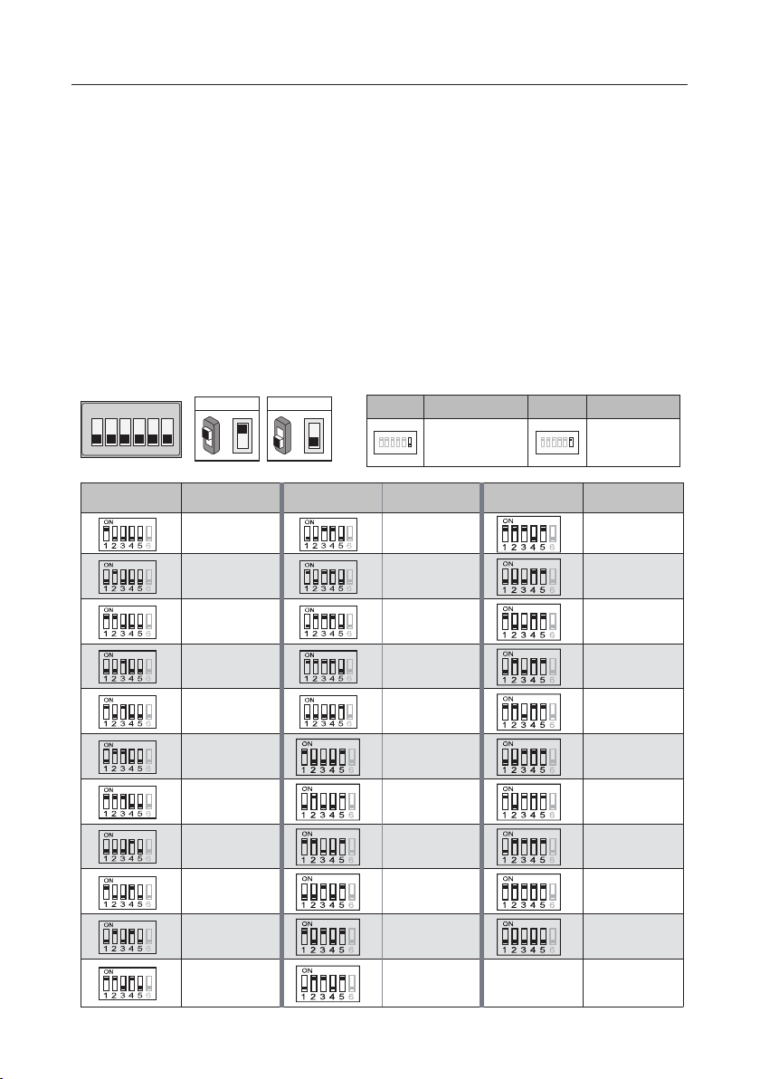
DIP Switches Settings Of Indoor Unit
TheDIPswitches are used tosettheusercodeforeachmonitor.Total6 bits can be cong-
ured.
• Bit-1 to Bit-5 are used for user code setting. The value range is from 1 to 32, which have 32
different codes for 32 apartments.
• When multi monitors need to be installed in one apartment, these monitors should use the
same user code, and the master/slave mode should be set on the monitor.
• Bit-6 is bus line terminal switch, which should be set to “ON” if the monitor is at the end of
bus line, otherwise be set to “OFF”.
Bit-6 switch setting
ON DIP
1 2 3 4 5 6
ON(1)
ON
=
Bit state User Code Bit state User Code Bit state User Code
Code=1 Code=12 Code=23
Code=2 Code=13 Code=24
Code=3 Code=14 Code=25
OFF(0)
ON
Bit state Setting Bit state Setting
=
ON DIP
1 2 3 4 5
When monitor is not
at the end of bus line.
6
ON DIP
1 2 3 4 5
When monitor is at
the end of bus line.
6
Code=4 Code=15 Code=26
Code=5 Code=16 Code=27
Code=6 Code=17 Code=28
Code=7 Code=18 Code=29
Code=8 Code=19 Code=30
Code=9 Code=20 Code=31
Code=10 Code=21 Code=32
Code=11 Code=22
-9-
Page 11
ON
RF CARD
RF CARD
ON
RF CARD
ON
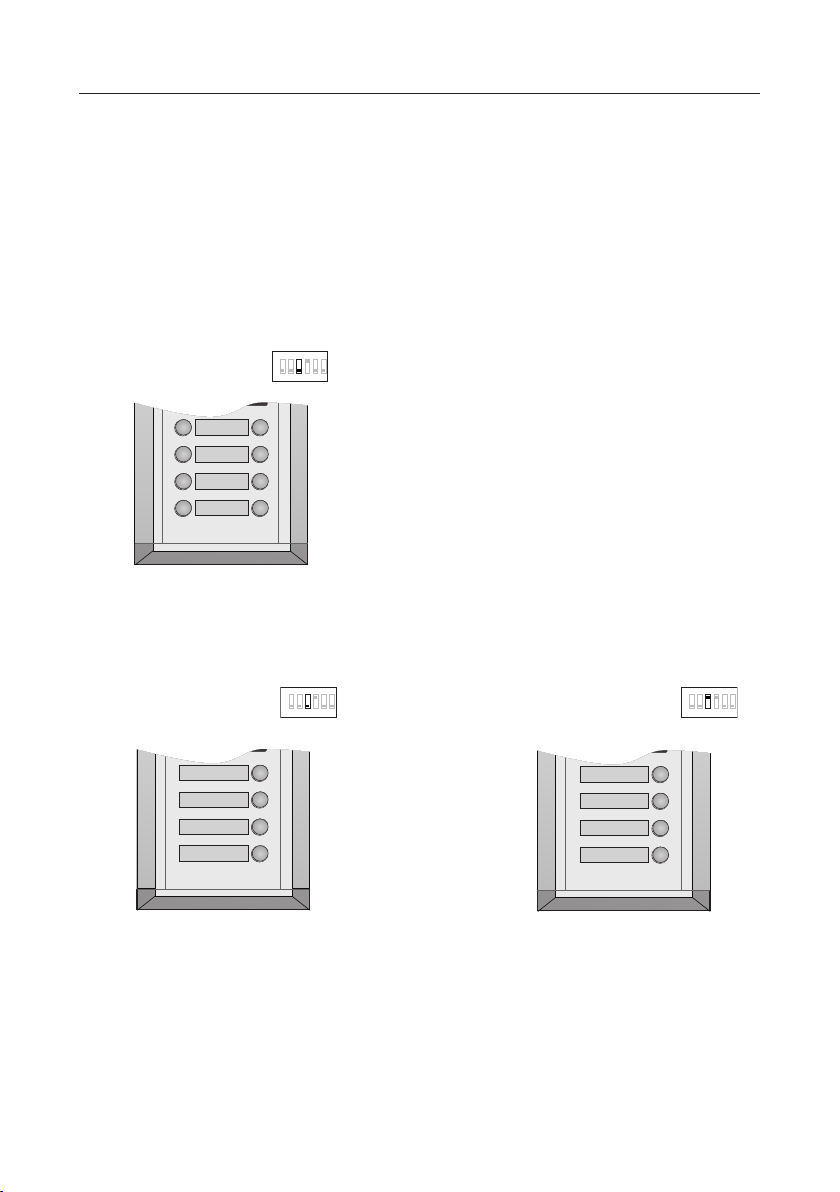
7. Call codes
The door station automatically assigns the call codes to the connected module’s buttons.
Regardless of the structure of the call button module, the button numbers are listed from
the top to bottom and from left to right (in the case of double row buttons):
In the case of double row buttons:
• DIP3 switch set to off
1 2 3 4 5 6
07 08
05 06
03 04
01 02
In the case of single row buttons:
• DIP3 switch set to off
1 2 3 4 5 6
08
06
04
02
• DIP3 switch set to on
1 2 3 4 5 6
04
03
02
01
-10-
Page 12
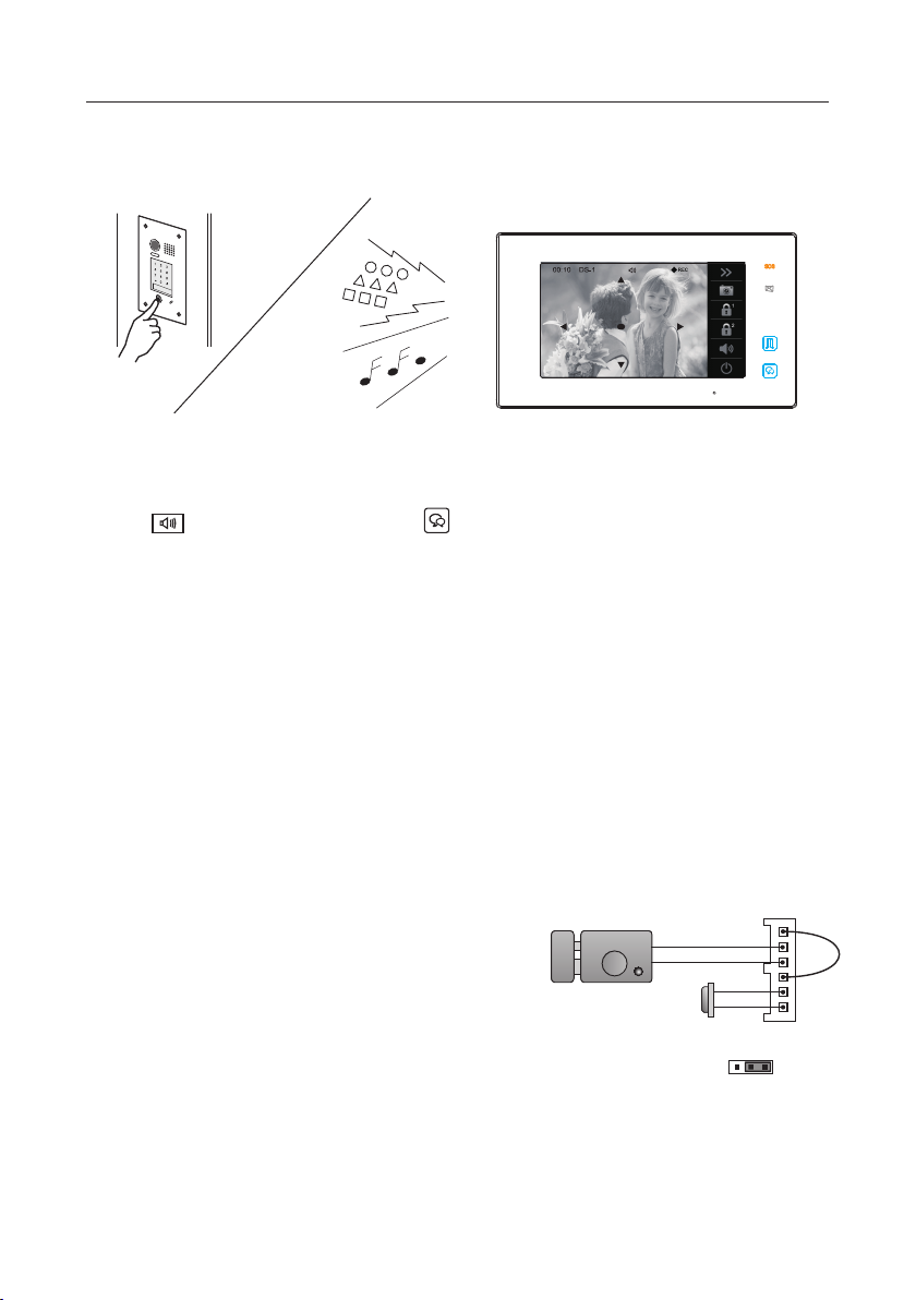
8. Answering a call
When there is a call from a video door station.The call tone sounds, an image will be
displayed on the screen.
Touch icon on screen or press TALK/MON button on the panel, begin
communicating hands free with the visitor for 90 seconds.
While communicating with the visitor, unlock the door, capture images/videos and adjust
screen&volume are available. More details,please refer to the following descriptions.
Note: 1.If nobody answers the phone, the screen will be turned off automatically after 40 seconds.
2.The 5 direction pad operation should make in effect with sh-eye door station.
9. Electric Lock Connection(NOT RECOMMENDED). See Page 12.
Note: NOT RECOMMENDED unless the door lock is less than 250mA. Please see Page 12
for HOW TO HOOK UP A DOOR RELEASE.
1) Door Lock Controlled with Internal Power
Power-on-to-Unlock type:
1. The door lock is limited to 12Vdc, and holding
current must be less than 250mA when using internal
power supply mode.
2. The Unlock Mode Parameter must be set to 0 (by
default).
3. Jumper set to 1-2 position for power-off-to-unlock
safety type(Normally closed mode); set to 2-3 position for power-on-to -unlock type(Normally open
12V 300mA
Jumper position in 2-3
-
+
Exit button
1 2 3
JP_LK
mode ).
4. If different unlocking time is needed,change the
unlock time on door station,detail information refer to
DT system technical guide .
+12V
LK LK+
N.O.
EBEB+
-11-
Page 13
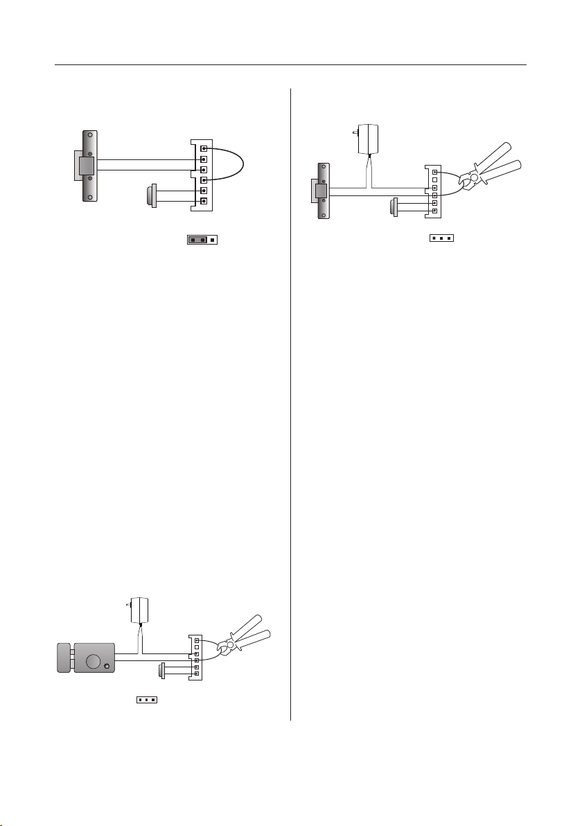
JP_LK
Power-off-to-Unlock type: Power-off-to-Unlock type:
12V 300mA
-
+
Exit button
Jumper position in 1-2
+12V
LK LK+
N.O.
EBEB+
1 2 3
2) Door Lock Controlled with External
Power
1. The external power supply must be used
according to the lock.
2. The jumper must be taken off before
connecting.
3. Setup the Unlock Mode Parameter for
different lock types
• Power-on-to-unlock type:Unlock
Mode=0(by default)
• Power-off-to-unlock type:Unlock
Mode=1
4. If different unlocking time is needed,
change the unlock time on door station,detail information refer to DT system technical guide .
Power-on-to-Unlock type:
Cut off the line
-
+
+
-
Exit button
1 2 3
JP_LK
+12V
LK - (GND)
LK+(COM)
N.O.
EBEB+
-
+
+
-
Exit button
Take off the Jumper
Cut off the line
+12V
LK - (GND)
LK+(COM)
N.O.
EBEB+
1 2 3
JP_LK
10. Specication
Power supply: 26Vdc
Power Consumption Of Outdoor Station:
1W in standby;
5W in working.
Power Consumption Of Indoor Unit:
0.29W in standby;
7W in working.
Unlock Power output: 12Vdc,250mA
Unlock timing: 1~99s
Working temperature: - 20ºC ~ +55ºC
Wiring: 2 wire, non-polarity
Dimension:
5.2(H)×8.9(W)×0.71(D) inch(Indoor Unit)
12.32(H)×5.04(W)×2.48(D)inch(ush)
12.32(H)×5.04(W)×2.76(D) inch(surface)
-12-
Page 14
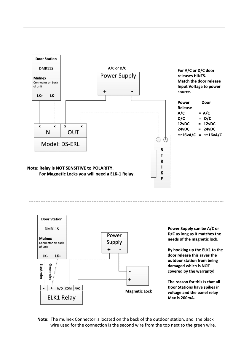
11. Hooking up a door release
-13-
Page 15

Note
-14-
Page 16

manual are preserved.
FOR TECHNICAL SUPPORT CALL
1516-387-6606 FROM 9AM TILL 4PM
MONDAY THRU FRIDAY
OUR WEBSITE WWW.NYWINT.COM
DK4761 & DK4781
 Loading...