

Page 1
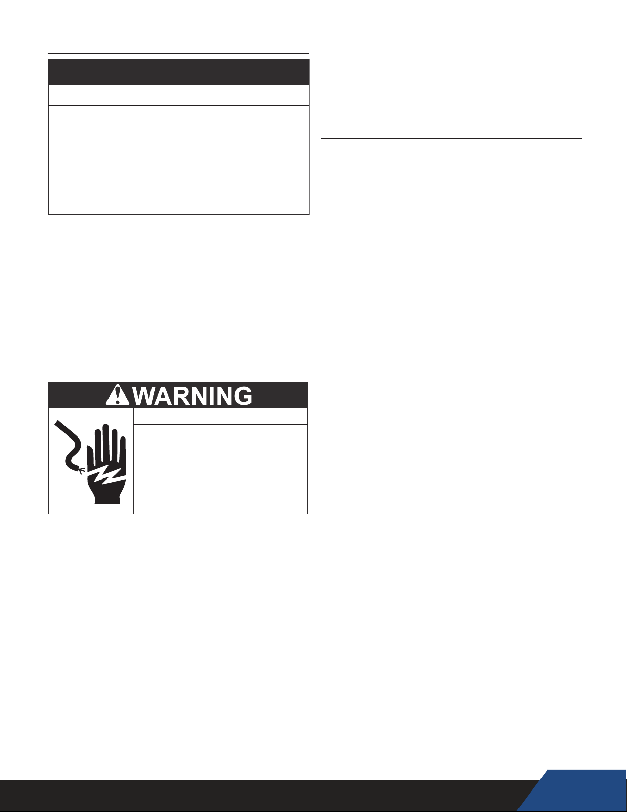
GROUNDING INSTRUCTIONS
This heat pump water heater must be grounded in accordance
with the National Electrical Code and/or local codes. These must
be followed in all cases. Failure to ground this water heater
properly may also cause erratic control system operation.
This heat pump water heater must be connected to a grounded
metal, permanent wiring system; or an equipment grounding
conductor must be run with the circuit conductors and connected
to the equipment grounding terminal or lead on the water heater.
Water temperature over 125°F (52°C)
can cause severe burns instantly
resulting in severe injury or death.
Children, the elderly and the
physically or mentally disabled are at
highest risk for scald injury.
Feel water before bathing or
showering.
Temperature limiting devices such as
mixing valves must be installed
when required by codes and to
ensure safe temperatures at fixtures.
2018
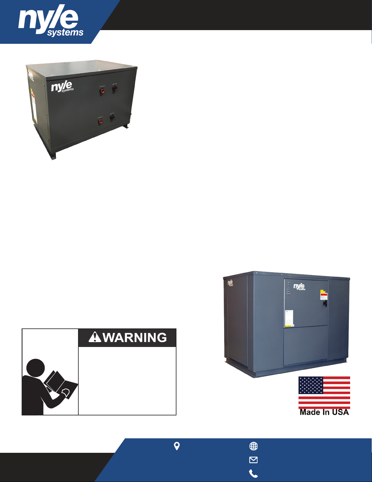
MODELS C25W-C250W
Installation-Operation-Service
Maintenance-Limited Warranty
FOR INDOOR/OUTDOOR INSTALLATION
User Manual
Geyser C-Series Water
Source Heat Pump Water
Heaters
Read and understand this instruction
manual and the safety messages
herein before installing, operating or
servicing this water heater.
Failure to follow these instructions and
safety messages could result in death
or serious injury.
This manual must remain with the
water heater.
PLACE THESE INSTRUCTIONS ADJACENT TO HEAT PUMP AND NOTIFY OWNER TO KEEP FOR FUTURE REFERENCE.
Nyle Systems
12 Stevens Rd
Brewer, ME 04412
www.nyle.com
watersales@nyle.com
800-777-6953
Page 2

Page 3

Table of Contents.................................................2
Condensed Unit Report.......................................4
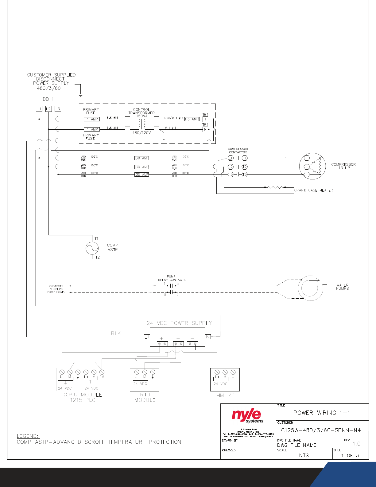
Unit Power Wiring.................................................5
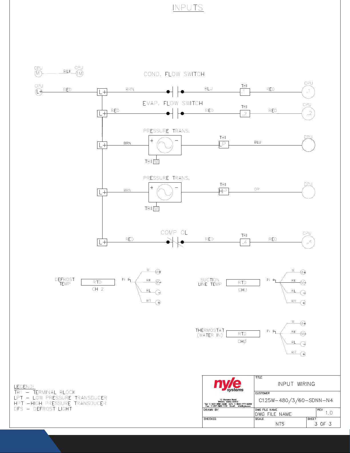
Unit Input Wiring...................................................6
Unit Output Wiring................................................7
Safe Installation, Use & Service...........................8
General Safety Information.....................................9
Precautions.........................................................9
Grounding Instructions............................................9
Introduction........................................................10
Qualications.......................................................10
Preparing for the Installation................................10
Principle of Operation..........................................11
The Refrigeration Cycle.......................................11
Source Water Temperature Range........................11
Water Temperature Range....................................11
Refrigerant Charge................................................11
Equipment Disposal...............................................11
Features & Components...................................12
Product Illustrations.............................................13
Rough in Dimensions.......................................13
Performance Specications................................13
Installation Requirements................................14
Water Temperature.............................................14
Maximum System Temperature..........................14
Inlet & Outlet Water Temperature.......................14
Source Water Temperature....................................14
Locating the Water Heater..................................14
Indoor/Outdoor Installation Requirements..........14
Freezing Temperatures.........................................14
Coastal Regions..................................................14
Heat Source.........................................................14
Clearances..........................................................15
Electrical Requirements......................................15
Voltage & Amperage Ratings..............................15
Minimum Circuit Ampacity & Maximum Fuse Size.16
Minimum Wire Size..............................................16
Water Piping.........................................................17
Minimum Pipe Size..............................................17
Pipe Support.........................................................17
Pipe Installation....................................................17
Cold Water Supply...............................................17
Water Pressure....................................................17
Closed Water Systems........................................17
Thermal Expansion..............................................17
Mixing Valves........................................................17
Contaminated Water............................................18
Temperature - Pressure Relief Valve.....................18
Tank Selection.....................................................18
Storage & Handling.............................................19
Installation.........................................................20
Required Tools & Materials.................................20
Installation & Startup Tools..................................20
Service Tools.........................................................20
Unit Placement......................................................20
Pad Mounting........................................................20
Electrical Connections..........................................21
Correct Voltage & Phase......................................21
Branch Circuit Disconnect Switch........................21
Water Connections................................................21
Installation Instructions........................................21
Single Tank Conguration....................................22
Multiple Tank Conguration..................................22
Standard Tank Thermostat...................................22
Temperature Sensor Installation..........................23
Installation Checklist..........................................24
Location................................................................24
Water Piping..........................................................24
Electrical..............................................................24
Pre-Startup Checklist........................................25
3 Phase Startup Procedures................................26
Initial Startup......................................................27
Startup Checklist................................................28
Startup.....................................................29
Electronic Temperature Controls.......................30
Functions Ranges & Settings................................31
Parameter Settings...............................................31
Screen Navigation.................................................31
Basic Mode...........................................................31
Advanced Mode...................................................32
Restricted Mode...................................................32
Programmable Logic Controls.............................33
PLC Controller......................................................33
Temperature & Setpoints.....................................33
Setpoint Ranges & Safeties.................................33
Master Screens.....................................................34
Home Screen........................................................34
Conguration Screen.............................................35
Alarm Screen........................................................35
Slave Screens.......................................................36
Alarm Screen.........................................................36
Stop Screen...........................................................36
Single Unit IP Address Cong Screen...................37
Terminology.............................................37
Alarm Screen.........................................................37
Stop Screen..........................................................38
Maintenance & Service.......................................39
Troubleshooting.........................................40
Limited Warranty...................................................44
Registration..........................................................45
Page 4
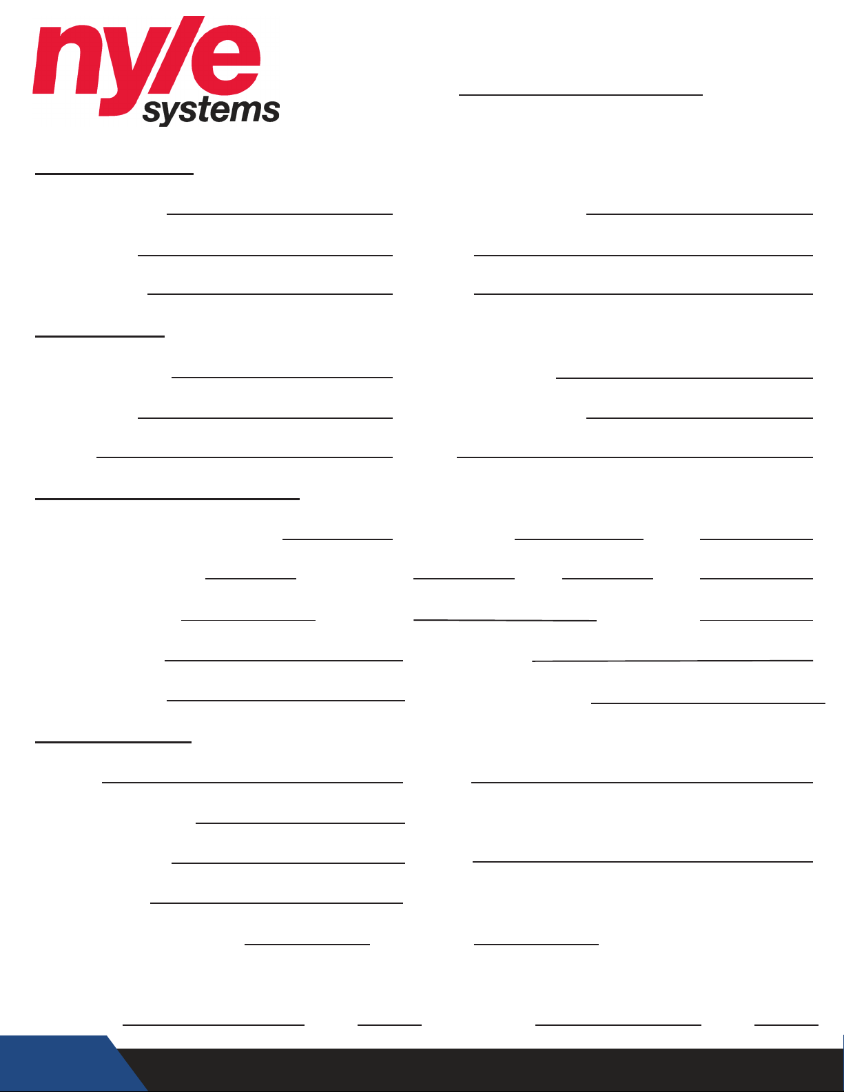
Unit Report
Date:
Basic Information
Company Name: Rep. Firm (If Applicable):
Unit Model #: Serial #:
Power Source: Controls:
Electrical Data
Transformer Size: Fuse/Breaker Size:
Compressor Time Delay:Compressor:
Blower: Fans:
Refrigeration Equipment Data
Size:Manufacturer:Thermal Expansion Valve Part #:
Manufacturer: Size: Part #:Solenoid Valve Coil:
Suction Valve Size: Discharge: Liquid Line:
Condenser Data: Evaporator Data:
Refrigerant Type:
Refrigerant Quantity:
Compressor Data
Model #: Serial #:
Connection Condition:
Crankcase Heater:
Voltage:
Capacitor MFD:
Low Pressure Switch Cut In: Cut Out:
Unit Physical Inspection: Pass / Fail
Tested By: Inspected By:Date: Date:
4
Page 5
PB
5
Page 6
AI0
AI1
6
I
I
PB
I
I
I
I
Page 7
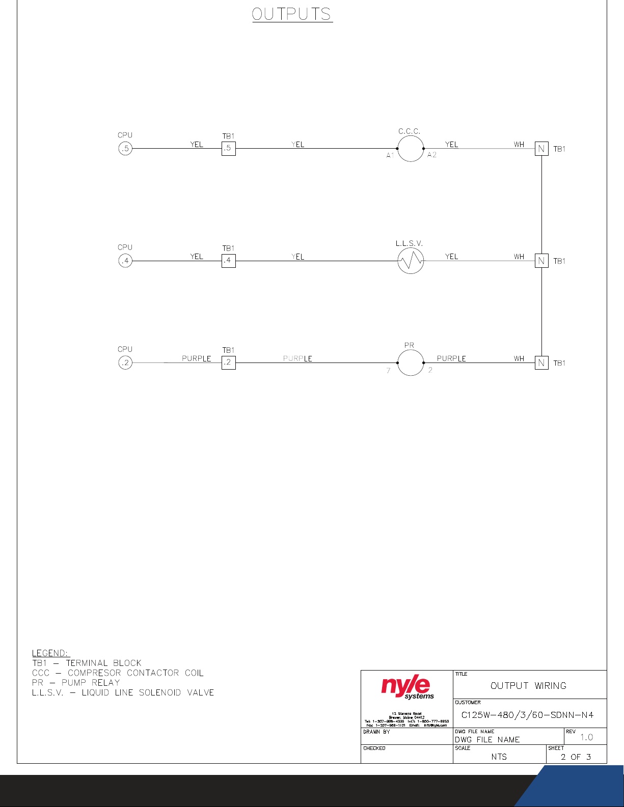
PB
7
Page 8
SAFE INSTALLATION, USE AND SERVICE
The proper installation, use and servicing of this commercial heat pump water heater is extremely important to your safety and the
safety of others.
Many safety-related messages and instructions have been provided in this manual and on your own heat pump water heater to warn
you and others of a potential injury hazard. Read and obey all safety messages and instructions throughout this manual. It is very
important that the meaning of each safety message is understood by you and others who install, use, or service this heat pump water
heater.
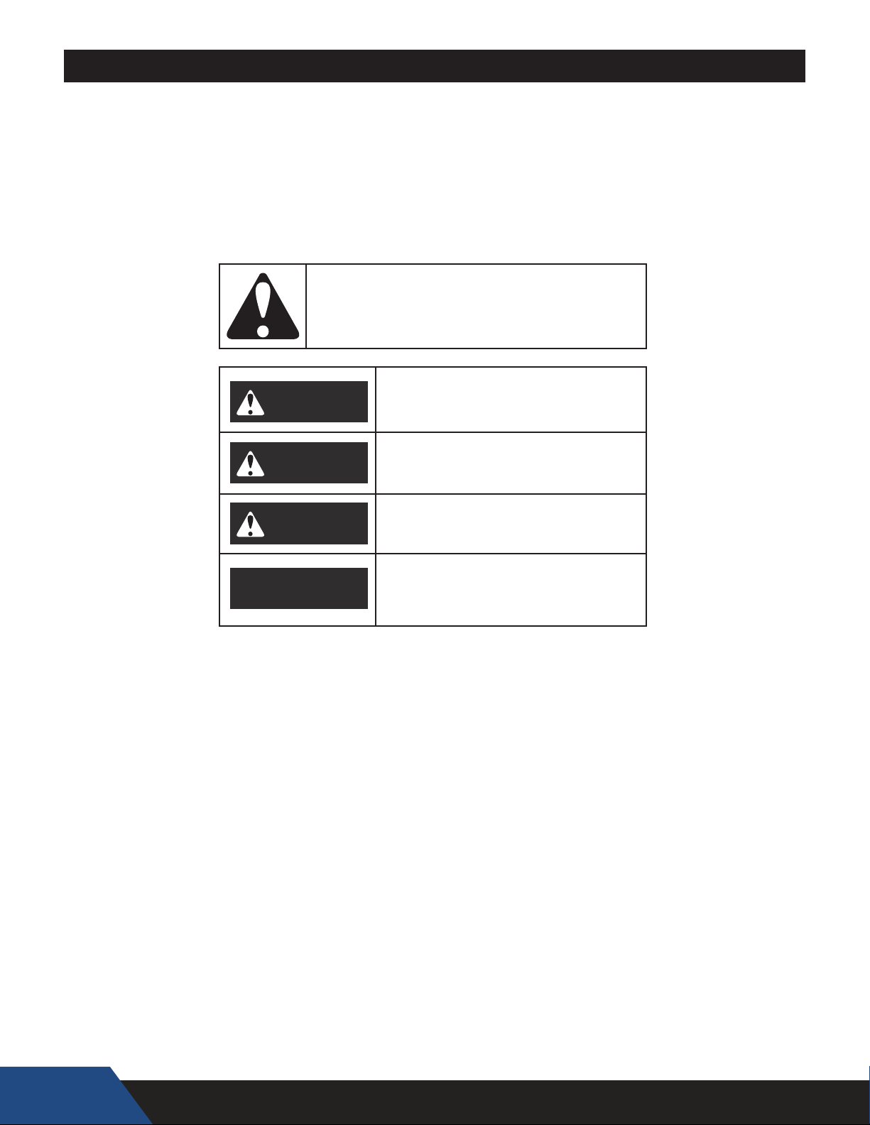
This is the safety alert symbol. It is used to alert you to
potential personal injury hazards. Obey all safety
messages that follow this symbol to avoid possible
injury or death.
DANGER indicates an imminently
DANGER
WARNING
hazardous situation which, if not avoided,
will result in injury or death.
WARNING indicates a potentially hazardous
situation which, if not avoided, could result
in injury or death.
CAUTION indicates a potentially hazardous
CAUTION
CAUTION
All safety messages will generally tell you about the type of hazard, what can happen if you do not follow the safety message, and
how to avoid the risk of injury.
The California Safe Drinking Water and Toxic Enforcement Act requires the Governor of California to publish a list of substances
known to the State of California to cause cancer, birth defects, or other reproductive harm, and requires businesses to warn of
potential exposure to such substances.
This product contains a chemical known to the State of California to cause cancer, birth defects, or other reproductive harm. This
appliance can cause low level exposure to some of the substances listed in the Act.
situation which, if not avoided, could result in
minor or moderate injury.
CAUTION used without the safety alert
symbol indicates a potentially hazardous
situation which, if not avoided, could result in
property damage.
8
Page 9
GENERAL SAFETY INFORMATION
PRECAUTIONS
DO NOT USE THIS APPLIANCE IF ANY PART HAS BEEN
UNDER WATER. Immediately call a qualied service agency to
inspect the appliance and to make a determination on what steps
should be taken next.
If the unit is exposed to the following, do not operate heater
until all corrective steps have been made by a qualied service
agency.
1. External re.
2. Damage.
3. Running without water.
When servicing this unit, verify the power to the unit is turned off prior to opening the control cabinet door.
CONTAINS REFRIGERANT!
System contains oil and refrigerant under high pressure. Recover
refrigerant to relieve pressure before opening the system. See unit
rating label for refrigerant type. Do not use non-approved refrigerants,
refrigerant substitutes, or refrigerant additives.
Failure to follow proper procedures or the use of non-approved
refrigerants, refrigerant substitutes, or refrigerant additives could
result in death or serious injury or equipment damage.
GROUNDING INSTRUCTIONS
This heat pump water heater must be grounded in accordance
with the National Electrical Code and/or local codes. These must
be followed in all cases. Failure to ground this water heater
properly may also cause erratic control system operation.
This heat pump water heater must be connected to a grounded
metal, permanent wiring system; or an equipment grounding
conductor must be run with the circuit conductors and connected
to the equipment grounding terminal or lead on the water heater.
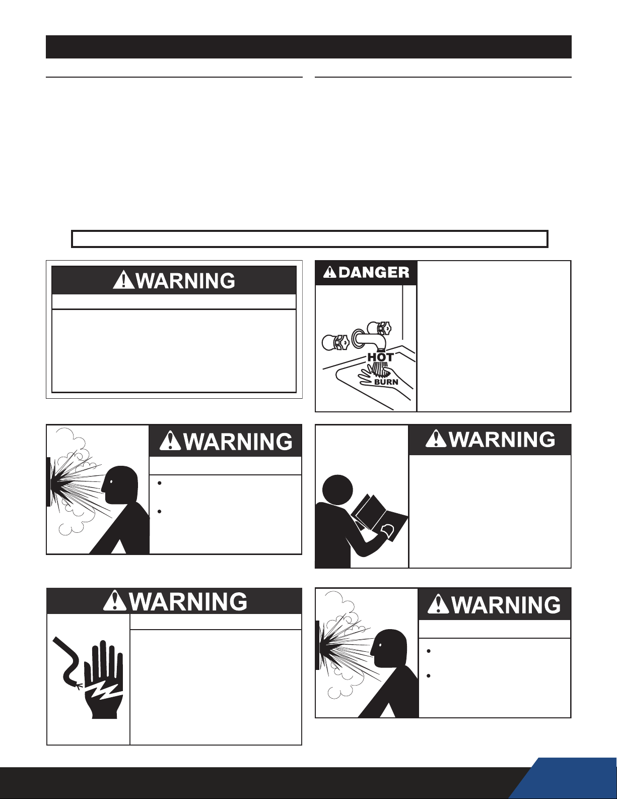
Water temperature over 125°F (52°C)
can cause severe burns instantly
resulting in severe injury or death.
Children, the elderly and the
physically or mentally disabled are at
highest risk for scald injury.
Feel water before bathing or
showering.
Temperature limiting devices such as
mixing valves must be installed
when required by codes and to
ensure safe temperatures at fixtures.
Explosion Hazard
Do not use oxygen to purge or
pressurize system for leak test.
Oxygen reacts violently with oil,
which can cause an explosion
resulting in severe personal
injury or death.
Electrical Shock Hazard
Turn off power to the water heater
•
before performing any service.
Label all wires prior to disconnecting
•
when performing service. Wiring errors
can cause improper and dangerous
operation.
Verify proper operation after servicing.
•
Failure to follow these instructions can
•
result in personal injury or death.
Read and understand this instruction
manual and the safety messages
herein before installing, operating or
servicing this water heater.
Failure to follow these instructions and
safety messages could result in death
or serious injury.
This manual must remain with the
water heater.
Explosion Hazard
Overheated water can cause
water tank explosion.
Properly sized temperature and
pressure relief valve must be
installed in the opening provided
on connected storage tanks.
9
Page 10
THIS WATER HEATING APPLIANCE.
INTRODUCTION
Thank You for purchasing this heat pump water heater. Properly
installed and maintained, it should give you years of trouble free
service.
Abbreviations found In this Instruction Manual include:
• HPWH - Heat Pump Water Heater
• ANSI - American National Standards Institute
• ASME - American Society of Mechanical Engineers
• NEC - National Electrical Code
• NFPA - National Fire Protection Association
• AHRI - Air-conditioning, Heating and Refrigeration Institute
QUALIFICATIONS
QUALIFIED INSTALLER OR SERVICE AGENCY:
Installation and service of this water heater requires ability
equivalent to that of a Qualied Agency (as dened by ANSI
below) in the eld involved. Installation skills such as plumbing,
electrical supply are required in addition to electrical testing skills
when performing service.
This heat pump water heater contains R-134a refrigerant and is
regulated as a stationary refrigeration appliance under Section
608 of the Clean Air Act. Servicing of the refrigeration circuit must
only be performed by agencies or individuals possessing Type II
or Universal certication as dened in Section 608 of the Clean
Air Act.
ANSI Z223.1 2006 Sec. 3.3.83: “Qualied Agency” - “Any
individual, rm, corporation or company that either in person or
through a representative is engaged in and is responsible for (a)
the installation, testing or replacement of gas piping or (b) the
connection, installation, testing, repair or servicing of appliances
and equipment; that is experienced in such work; that is familiar
with all precautions required; and that has complied with all the
requirements of the authority having jurisdiction.”
PREPARING FOR THE INSTALLATION
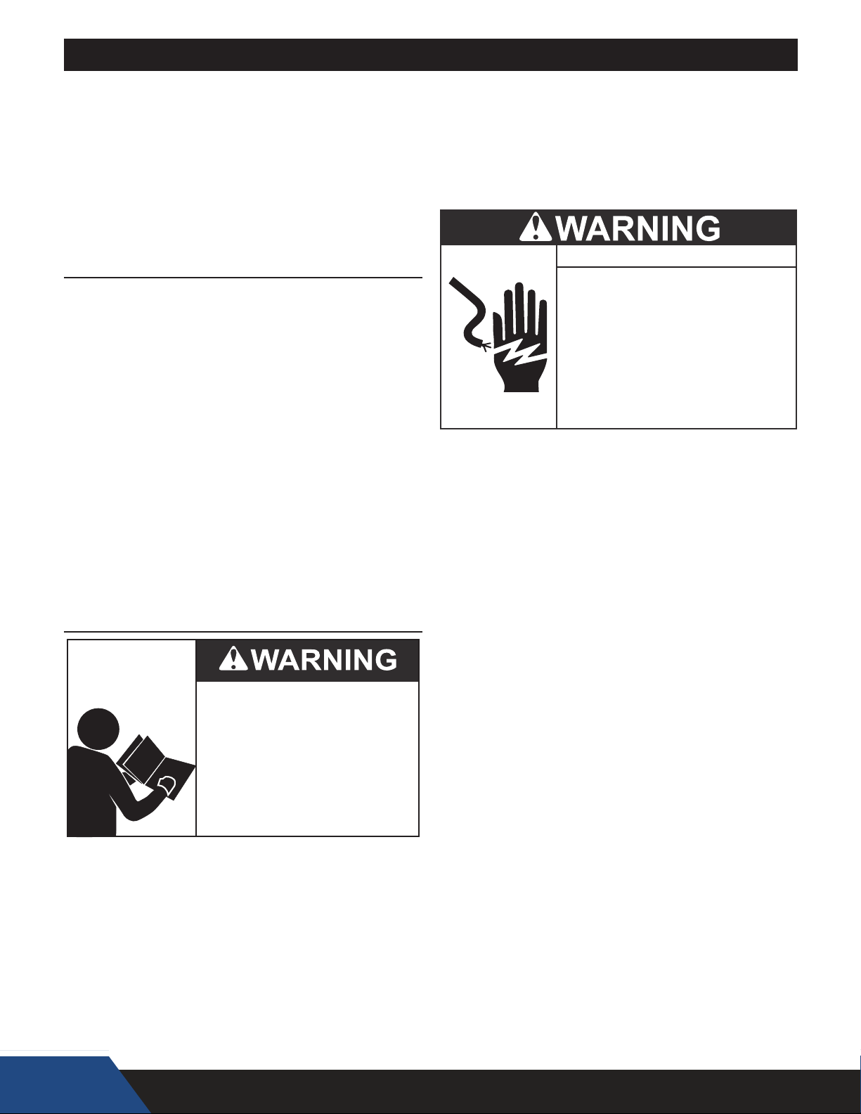
Read and understand this instruction
manual and the safety messages
herein before installing, operating or
servicing this water heater.
Failure to follow these instructions and
safety messages could result in death
or serious injury.
This manual must remain with the
water heater.
1. Read the “General Safety Information” section of this manual
rst and then the entire manual carefully. If you don’t follow
the safety rules, the heat pump water heater may not operate
safely. It could cause DEATH, SERIOUS BODILY INJURY
AND/OR PROPERTY DAMAGE.
This manual contains instructions for the installation,
operation, and maintenance of the heat pump water heater
(HPWH). It also contains warnings throughout the manual
that you must read and be aware of. All warnings and all
instructions are essential to the proper operation of the
HPWH and your safety. READ THE ENTIRE MANUAL
BEFORE ATTEMPTING TO INSTALL OR OPERATE
Detailed installation diagrams are in this manual. These
diagrams will serve to provide the installer with a reference
for the materials and suggested methods of piping. IT
IS NECESSARY THAT ALL WATER PIPING AND THE
ELECTRICAL WIRING BE INSTALLED AND CONNECTED
AS SHOWN IN THE DIAGRAMS.
Particular attention should be given to the installation of the
system (tank) temperature control. See page 21.
Electrical Shock Hazard
Turn off power to the water heater
•
before performing any service.
Label all wires prior to disconnecting
•
when performing service. Wiring errors
can cause improper and dangerous
operation.
Verify proper operation after servicing.
•
Failure to follow these instructions can
•
result in personal injury or death.
Be sure to turn off power when working on or near the
electrical system of the heat pump. Never touch electrical
components with wet hands or when standing in water.
When replacing fuses always use the correct size for the
circuit.
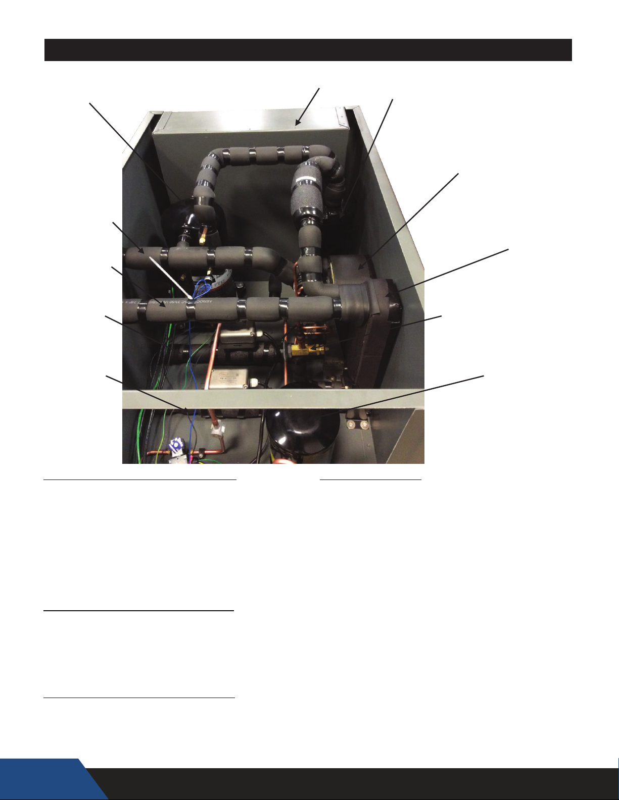
The principal components of the HPWH are identified in the
Features And Components section of this manual on page
12. The rating label on the HPWH also provides useful
information. These references should be used to identify the
heat pump, its components and optional equipment.
2. The installation must conform with these instructions and the
local code authority having jurisdiction and the requirements
of the power company. In the absence of local codes, the
installation must comply with the latest editions of the
National Electrical Code, ANSI/NFPA 70 or the Canadian
Electrical Code CSA C22.1. The National Electrical Code
may be ordered from: National Fire Protection Association,
1 Batterymarch Park, Quincy, MA 02269. The Canadian
Electrical Code is available from the Canadian Standards
Association, 8501 East Pleasant Valley Road, Cleveland,
OH 44131.
3. If after reading this manual you have any questions or do not
understand any portion of the instructions DO NOT proceed
with the installation. Call the toll free number listed on the
back cover of this manual for technical assistance.
4. In order to expedite your request, please have full model and
serial number available for the technician.
5. Carefully consider your intended placement and location for
the HPWH. See Locating The Water Heater on page 24.
6. Installation and service of this HPWH requires ability
equivalent to that of a licensed tradesman or Qualified Agency
in the field involved. See Qualifications on page 8.
7. For installation in California the HPWH appliance must be
braced or anchored to avoid falling or moving during an
earthquake. Instructions may be obtained from California
Office of the State Architect, 1102 Q Street, Suite 5100,
Sacramento, CA 95811.
10
Page 11
8. Ensure the power supply voltage and phase at the job site
matches the power requirements on the HPWH rating label
before installation begins. Energizing the HPWH with the
wrong voltage or phase will cause permanent damage to the
unit.
PRINCIPLE OF OPERATION
The appliances covered by this Instruction Manual are
commercial water-to-water heat pump water heaters (HPWH).
Operation of the HPWH is simple in the fact that we are
transferring heat energy from a water source to a DHW tank by
means of a compressed refrigeration cycle. Recovering and
using this waste heat increases the overall energy
efficiency of the building.
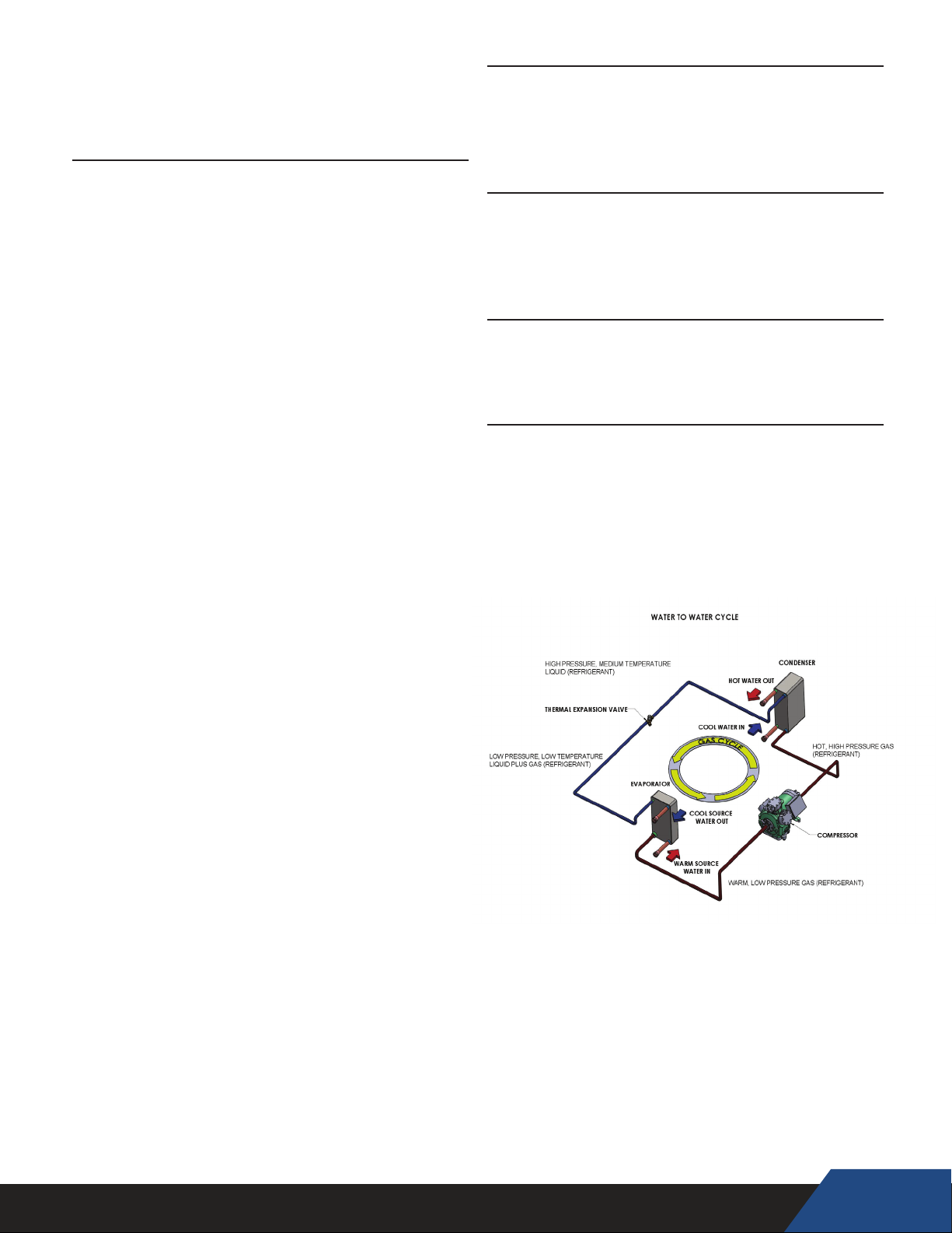
THE REFRIGERATION CYCLE
Refer to Figure 1 on page 12 for the location of
components mentioned in this section.
Refrigerant is circulated through the refrigeration circuit by a
Compressor. The refrigerant is a high temperature high
pressure gas when it leaves the compressor. Refrigerant
flows from the compressor through the Hot Gas Line to the
Condenser.
The condenser is a refrigerant-to-water heat exchanger with two
circuits, refrigerant flows through one circuit and water through
the other. The high temperature refrigerant gas transfers its heat
to the water flowing through the condenser. As the refrigerant
gas cools inside the condenser it changes state (condenses)
from a gas to a liquid. A Water Pump circulates water
through the condenser.
Refrigerant leaving the condenser is a medium temperature
high pressure liquid. It flows through the Liquid Line to the
Thermostatic Expansion Valve. The thermostatic expansion
valve (TXV) regulates the flow of refrigerant into the
Evaporator. The evaporator is a single wall brazed plate source
water-to-refrigerant heat exchanger. The refrigerant changes
state (boils/evaporates) from a liquid state back into a gas
(vapor) in the evaporator.
The refrigerant flows out of the evaporator through the Suction
Line and into the Accumulator. The accumulator traps any
liquid refrigerant the evaporator is unable to vaporize during
low temperature operating conditions. The
accumulator prevents liquid refrigerant from entering the
compressor where it could damage internal components.
Low temperature, low pressure refrigerant gas (vapor) is
drawn out of the accumulator by the compressor. The
compressor increases the pressure and temperature of the
refrigerant gas circulating it to the condenser again
where the refrigeration cycle starts over or continues.
SOURCE WATER TEMPERATURE RANGE
The entering source water temperature operating range for
the HPWH is 40°F to 100°F (4°C to 38°C).
When the HPWH is operating properly the source water
temperature drop through the evaporator (heat exchanger) will
be approximately 8°F to 11°F (-13°C to -12°C).
WATER TEMPERATURE RANGE
The inlet (entering) water temperature operating range for the
HPWH is 40°F to 140°F (4°C to 60°C).
The HPWH will heat potable water up to 150°F.
When the HPWH is operating properly the water temperature
rise through the condenser (heat exchanger) will be
approximately 8°F to 12°F (4°C to 7°C).
REFRIGERANT CHARGE
The HPWH is factory-charged with R-134a refrigerant. The
refrigerant charge is weighed in at the factory. See Table
9 on page 34. It should not be necessary to add or
remove refrigerant during installation or start up.
EQUIPMENT DISPOSAL
This heat pump water heater contains R-134a refrigerant and is
regulated as a stationary refrigeration appliance under Section
608 of the Clean Air Act. Disposal of this unit must be performed
in accordance with the provisions in Section 608 of the Clean Air
Act and any state or local regulations that may also apply. See
Qualifications on page 10.
11
Page 12
RECIEVER
COMPONENT REFRIGERATION CIRCUIT
COMPRESSOR
CONDENSER (HEAT EXCHANGER)
RECIEVER
THERMOSTATIC EXPANSION VALVE (TXV)
EVAPORATOR (HEAT EXCHANGER)
ACCUMULATOR
COMPONENT HEATED WATER CIRCUIT
HEATED WATER INLET
CONDENSER (HEAT EXCHANGER)
HEATED WATER OUTLET
COMPONENT SOURCE WATER CIRCUIT
SOURCE WATER INLET
EVAPORATOR (HEAT EXCHANGER)
SOURCE WATER OUTLET
FEATURES AND COMPONENTS
ELECTRICAL PANEL
ACCUMULATOR
EVAPORATOR
(HEAT EXCHANGER)
(WATER TO REFRIGERANT)
SOURCE
WATER OUTLET
HEATE D
WATER OUTLET
SOURCE
WATER INLET
HEATE D
WATER INLET
COMPONENT REFRIGERATION CIRCUIT
REFRIGERANT STATE
CONDENSER
(HEAT EXCHANGER)
(REFRIGERANT TO POTABLE WATER)
THERMOSTATIC
EXPANSION VAVLE
(TXV)
COMPRESSOR
COMPRESSOR
CONDENSER (HEAT EXCHANGER)
RECIEVER
THERMOSTATIC EXPANSION VALVE (TXV)
EVAPORATOR (HEAT EXCHANGER)
ACCUMULATOR
COMPONENT HEATED WATER CIRCUIT
HEATED WATER INLET
CONDENSER (HEAT EXCHANGER)
HEATED WATER OUTLET
COMPONENT SOURCE WATER CIRCUIT
SOURCE WATER INLET
EVAPORATOR (HEAT EXCHANGER)
SOURCE WATER OUTLET
12
GAS
GAS TO LIQUID
LIQUID
LIQUID
LIQUID TO GAS
GAS / LIQUID
Page 13
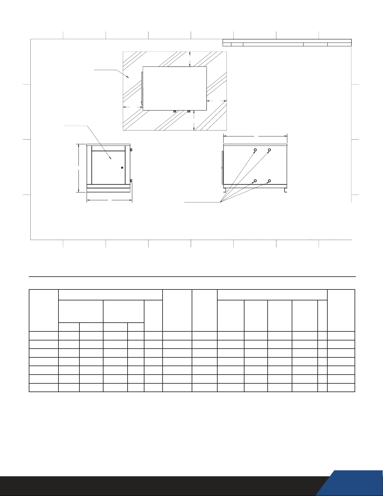
Figure 2
PERFORMANCE SPECIFICATIONS
ROUGH IN DIMENSIONS
Dimensions
27
1
2
"
28"
28"
ELECTRICAL
SERVICE DOOR
REFRIGERATION
SERVICE DOOR
34
1
2
"
3'-0"
5'-11
1
2
"
C270WM
SERVICE AREA
35
1
2
"
61
1
8
"
62
3
8
"
FRONT
WATER CONNECTIONS
71”
8 7 5 4 2
ZONE
REV.
3 16
DESCRIPTION
REVISIONS
DATE
APPROVED
D
C
ELECTRICAL
SERVICE DOOR
B
A
8
C
7 5 4
SERVICE AREA
B
2'0"
FRONT
1'6"
2'0"
2'0"
WATER CONNECTIONS
PROPRIETARY AND CONFIDENTIAL:
THE INFORMATION CONTAINED IN THIS
DRAWING IS THE SOLE PROPERTY OF
NYLE SYSTEMS LLC. ANY REPRODUCTION
IN PART OR AS A WHOLE WITHOUT THE
WRITTEN PERMISSION OF NYLE SYSTEMS
LLC IS PROHIBITED.
UNLESS OTHERWISE SPECIFIED:
DIMENSIONS ARE IN INCHES
TOLERANCES:
FRACTIONAL
DECIMAL
ANGULAR MACH
ANGULAR BEND
DRAWN
CHECKED
EDITED
D
C
A
B
TITLE:
1/16"
0.02"
NAME
1/2°
1°
DATE
10/5/2017
36
PART NO:
MATERIAL:
MATERIAL <NOT SPECIFIED>
FINISH:
C60W BASE CABINET
REVISION:
SHEET:
SCALE:
2
A-
1 OF 1
1:12
DEPT:
SENGINEERING
SHEET SIZE:
B
WEIGHT (lbs):
51.26
1
A
5
12
COP
4.4
4.7
4.6
SOURCE
WATER
FLOW
(GPM)
9.6
15
WATER
FLOW
(GPM)
12
20
5.4
INLET
OUTLET
WATER
(FNPT)
3/4”
1"
1.5"
20 25 1.5”
30
40
50
1.5”
2”
DIMENSIONS
LENGTHA WIDTHB HEIGHT
36.125
38.125
27.25
48.125
48.125
61
TABLE 1
MODEL
NUMBER
C25W
C60W
C90W
C125W
C185W
C250W
HEATING
CAPACITY
kW Btu/hr* Btu/hr Tons
8
17
32
43
64
81
PERFORMANCE
WATER
28,500 22,250 2 4.5 4
57,850 45,400
110,400 84,000 9 4.6
146,900
220,100 169,500 18
278,300 23 4.5 36
COOLING
CAPACITY
116,000
216,450
All unit foot print dimensions are in inches. Weights are approximate shipping weights.
*Performance rating at 75ºF Entering Source Water Temperature and 100ºF Entering Heated Water Temperature. (EWT)
COP = Coefficient Of Performance
All models standard 208/230 VAC, 3Ø, 60 Hz OR
Optional: 460 VAC, 3Ø, 60 Hz or 400/3/50
24.875
27.25
28.875
28.875
38.125 28.875
37.375
37.375
42
38.125
38.125
51.125
WEIGHT
(LBS)
C
225
275
350
450
500
1,300
13
Page 14

INSTALLATION REQUIREMENTS
CAUTION
Read all installation requirements in this manual before installation
begins. The installation must conform to these instructions and
all local and national code authority having jurisdiction.
Costs to diagnose, perform service and repair damage caused
by installation errors are not covered under the limited warranty.
Costs to correct installation errors are not covered under the
limited warranty.
WATER TEMPERATURE
MAXIMUM SYSTEM TEMPERATURE
The HPWH units covered in this manual are capable of
maintaining a maximum system/storage tank temperature of
150°F (66°C). Some commercial water heating applications
may require higher temperatures. Install a booster water heater
downstream from the storage tank for temperatures above
150°F (66°C). See Figure 8 on page 22.
INLET & OUTLET WATER TEMPERATURE
The inlet (entering) water temperature operating range for the
HPWH is 40°F to 140°F (4.4°C to 60°C). The water temperature
rise (Delta T - ∆T) through the condenser (heat exchanger) will
be approximately 8°F to 12°F (4°C to 7°C).
Outlet water temperatures up to 152°F (67°C) are possible
during normal operation. Exposure to water temperatures this
high can cause serious bodily injury or death. See Mixing
Valves and Table 5 on pages 17-18.
Service & Installation Notes:
If the inlet (entering) water temperature is outside the operating
temperature range for extended periods the control system may
lock out on high or low refrigerant pressure switch events/trips.
When the control system locks out on a refrigerant pressure
switch event the compressor will stop running, the blower and
circulation pump (on models equipped with factory installed
pump) will continue to operate. This is a hard lock out condition.
The control system is manually reset by cycling power to the
HPWH off and then on again.
The tank thermostat must not be set any higher than 150°F
(66°C) to prevent control system lock outs.
Ground water temperatures can fall below 50°F (10°C) for
extended periods during winter months in many regions. For this
reason the cold water supply lines and should not be connected
directly to the HPWH inlet or T tted into the inlet (return) water
piping. The cold water supply lines should be connected directly
to the storage tank only. See the Piping Diagrams starting on
page 35 in this manual for more information.
SOURCE WATER TEMPERATURE
ENTERING SOURCE WATER TEMPERATURE
The entering source water temperature range of operation for
the unit is 40° - 100°F (4.4°C to 38°C). The source temperature
drop (Delta T - ∆T) through the evaporator (heat exchanger) will
be approximately 8°F to 12°F (-13°C to -12°C).
If the source water temperature is outside this operating
range the HPWH unit’s Limit Thermostat will discontinue
heating operation until the entering source water temperature
returns to this operating range.
LOCATING THE WATER HEATER
PROPERTY DAMAGE!
All water heaters may eventually leak.
•
• Do not install without adequate drainage.
INSTALLATION
Carefully choose a location for the HPWH unit. Placement is a
very important consideration for optimal performance and
safety.
Locate the HPWH near a oor drain. The unit should be located
in an area where leakage from the HPWH unit or the storage tank
it is connected to will not result in damage to the area adjacent
to the water heater or to lower floors of the structure. See Unit
Placement on page 20.
FREEZING TEMPERATURES
The HPWH unit must not be installed in space where freezing
temperature will occur, without a low ambient air kit.
Exposure to freezing ambient temperatures below 32°F (0°
C) may result in severe damage to internal components.
Damage caused by exposure to freezing temperatures is not
covered under the limited warranty.
COASTAL REGIONS
When the HPWH will be installed within 5 miles of a seacoast
the optional Corrosive Duty Package is recommended. The
corrosive duty package includes a stainless steel cabinet.
Damage caused to units not equipped with the corrosive
duty package in coastal regions is not covered under the limited
warranty.
HEAT SOURCE
The HPWH unit should be located where there is adequate
source water from which to extract waste heat and where the
source water cooling benefit can be utilized when possible.
14
Page 15
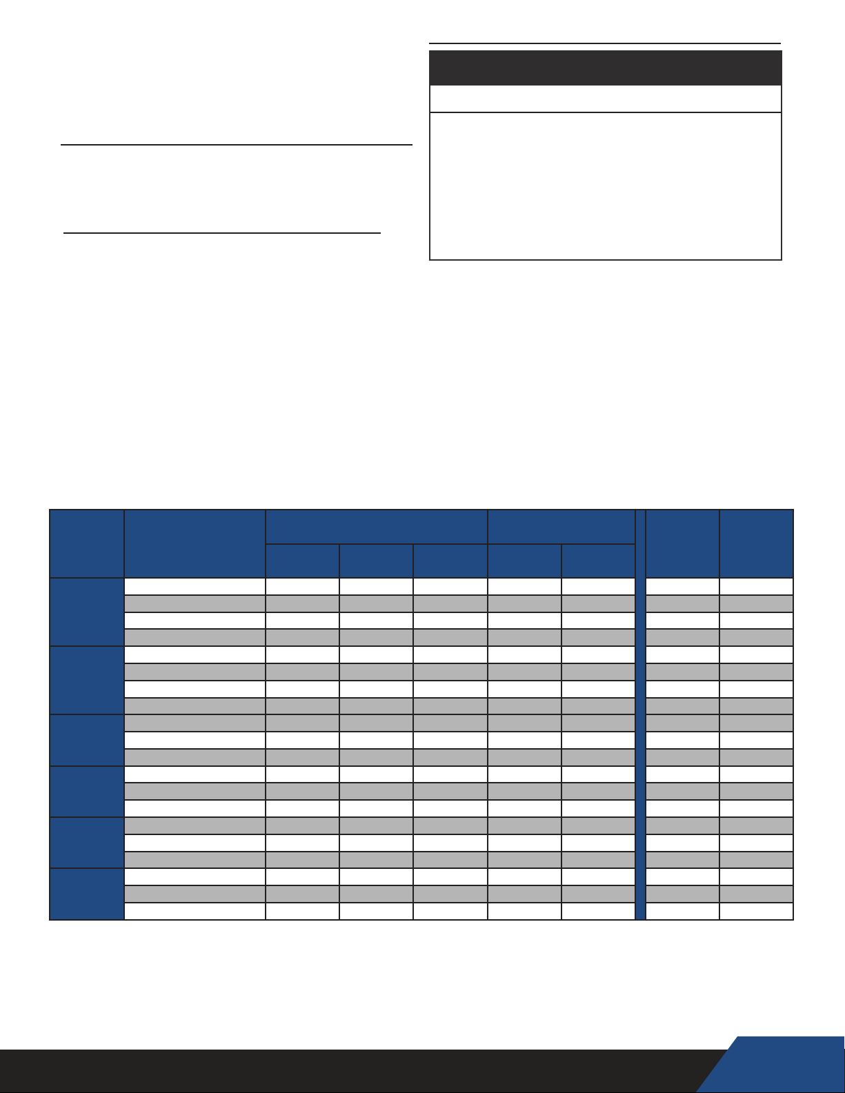
ELECTRICAL REQUIREMENTS
CLEARANCES
To ensure optimal performance a minimum of 36" clearance is
required from the front of the HPWH unit and any
wall obstruction. 24" is acceptable on all other sides.
Abbreviation Denitions For Table 2 Figure 3
RLA-Rated Load Amps
FLA-Full Load Amps
LRA-Locked Rotor Amps
MCA-Minimum Circuit Ampacity
MCC-Maximum Continuous Current
MFS-Maximum Fuse Size
TABLE 2
Figure 3
CAUTION
CORRECT POWER SUPPLY!
Ensure the power supply at the job site matches the
•
voltage and phase listed on the HPWH rating label
before connecting power to the HPWH unit.
Energizing the HPWH with the wrong voltage or phase
•
will cause permanent damage to the HPWH unit.
Damage caused to the HPWH as the result of applying
•
the wrong voltage or phase is not covered under the
limited warranty.
Ensure the power supply voltage and phase at the job site
matches the power supply ratings listed on the HPWH data
sticker label BEFORE INSTALLATION BEGINS.
The installation must conform with these instructions and the
local code authority having jurisdiction and the requirements
of the power company. In the absence of local codes, the
installation must comply with the current editions of the National
Electrical Code, ANSI/NFPA 70 or the Canadian Electrical Code
CSA C22.1.
Voltage applied to the HPWH should not vary more than +5% to
-10% of the voltage requirement listed on the HPWH rating label
for satisfactory operation.
VOLTAGE & AMPERAGE RATINGS
Model Volts/Phase/HZ
208-230/1/60 16.0 25.0 2.5 1.4 2.5 22 25
C25W
C60W
C90W
C125W
C185W
C250W
208-230/3/60 9.0 14.0 2.5 1.4 2.5 13 15
440-480/3/60 4.5 7.0 2.5 1.4 2.5 7 10
575/3/60 3.8 6.0 3.0 1.4 3.0 7 10
208-230/1/60 28.2 44.0 5.5 1.9 5.5 38 40
208-230/3/60 20.2 31.5 6.0 1.9 6.0 28 30
440-480/3/60 9.1 14.2 6.0 1.9 6.0 14 15
575/3/60 7.1 11.0 6.0 1.9 6.0 11 15
208-230/3/60 35.3 55.0 10.0 1.9 10.0 46 50
440-480/3/60 17.9 28.0 10.0 1.9 10.0 25 30
575/3/60 11.5 18.0 10.0 1.9 10.0 17 20
208-230/3/60 48.1 75.0 13.0 4.9 13.0 65 70
440-480/3/60 21.8 34.0 13.0 4.9 13.0 33 35
575/3/60 18.6 29.0 13.0 4.9 13.0 23 30
208-230/3/60 73.1 114.0 20.0 4.9 20.0 97 100
440-480/3/60 30.1 47.0 20.0 4.9 20.0 43 45
575/3/60 24.4 38.0 20.0 4.9 20.0 36 40
208-230/3/60 90.7 127.0 25.0 2 25.0 116 125
440-480/3/60 45.7 64.0 25.0 2 25.0 59 60
575/3/60 37.9 65.0 25.0 1 25.0 49 50
Compressor PUMP
MCA MFS
RLA MCC HP FLA HP
15
Page 16
MINIMUM CIRCUIT AMPACITY & MAXIMUM FUSE SIZE
Electrical Shock Hazard
Before removing any access panels or
•
servicing the water heater, make sure
the electrical supply to the water heater
is turned “OFF.”
Failure to do this could result in death,
•
serious bodily injury, or property
damage.
MINIMUM WIRE SIZE
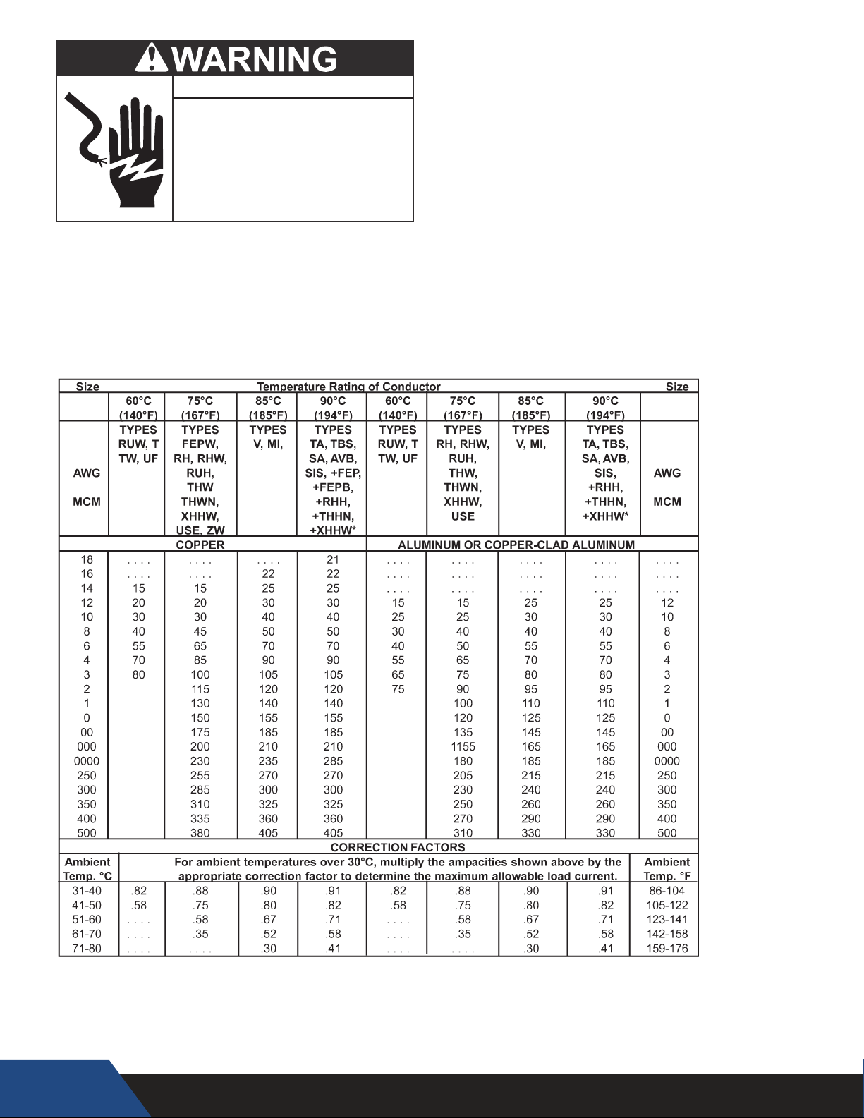
Allowable Ampacities of Insulated Conductors
Single-phase heat pump water heaters are two wire circuits. Three-phase heaters are three wire circuits. In addition to the foregoing,
a grounded conductor is required. Not more than three conductors in raceway, cable, or earth (directly buried), based on ambient
temperature of 30°C (86°F)
TABLE 3
Table 2 on page 15 provides the MCA (Minimum Circuit
Ampacity) and MFS (Maximum Fuse Size). Use MCA to select
the minimum field wires size to power the unit and MFS to select
the maximum fuse size for over current protection as follows:
Where: MCA= C x 1.25
MFS = C x 2.25
C - Compressor
+The load current rating and the overcurrent protection for these conductors shall not exceed 15 amperes for 14 AWG. 20 amperes for 12 AWG and 30 amperes for
10 AWG copper; or 15 amperes for 12 AWG and 25 amperes for 10 AWG aluminum and copper-clad aluminum.
*For dry locations only. See 75°C column for wet locations.
16
Page 17
WATER PIPING
CLOSED WATER SYSTEMS
Read all installation requirements in this manual before
installation begins.
The water piping installation must conform to these instructions
and to all local and national code authority having jurisdiction.
Costs to diagnose, perform service and repair damage caused
by installation errors are not covered under the limited warranty.
Costs to correct installation errors are not covered under the
limited warranty.
MINIMUM PIPE SIZE
The inlet (return) and outlet (supply) water piping installed
between the HPWH unit and the storage tank must not be
smaller than the water connection sizes on the HPWH. See
Table 4, below, for water line connection sizes and water flow
rates.
Water line sizing is a critical installation requirement.
Installing undersized water piping between the storage tank
and the HPWH unit will cause insufficient water flow and will
have an adverse impact on performance and equipment life.
Table 4
WATER CONNECTIONS AND FLOW
UNIT GPM CONNECTION SIZE (INCH)
C25W
C60W
C90W
C125W
C185W
C250W
5.4
12
20
25
40 1.5"
50
¾"
1"
1.5"
1.5"
2”
2"
Water supply systems may, because of code requirements
or such conditions as high line pressure, among others, have
installed devices such as pressure reducing valves, check
valves, and back ow preventers. Devices such as these cause
the water system to be a closed system.
THERMAL EXPANSION
As water is heated, it expands (thermal expansion). In a closed
system the volume of water will grow when it is heated. As the
volume of water grows there will be a corresponding increase
in water pressure due to thermal expansion. Thermal expansion
can cause premature failure (leakage) of storage tanks, water
heaters and HPWH components such as the condenser.
Leakage caused by thermal expansion is not covered under the
HPWH limited warranty.
Thermal expansion can also cause intermittent TemperaturePressure Relief Valve operation: water discharged due to
excessive pressure build up. The Temperature-Pressure Relief
Valve is not intended for the constant relief of thermal expansion.
A properly sized thermal expansion tank must be installed on
all closed systems to control the harmful effects of thermal
expansion. Contact a local plumbing service agency to have a
thermal expansion tank installed on all closed water systems.
MIXING VALVES
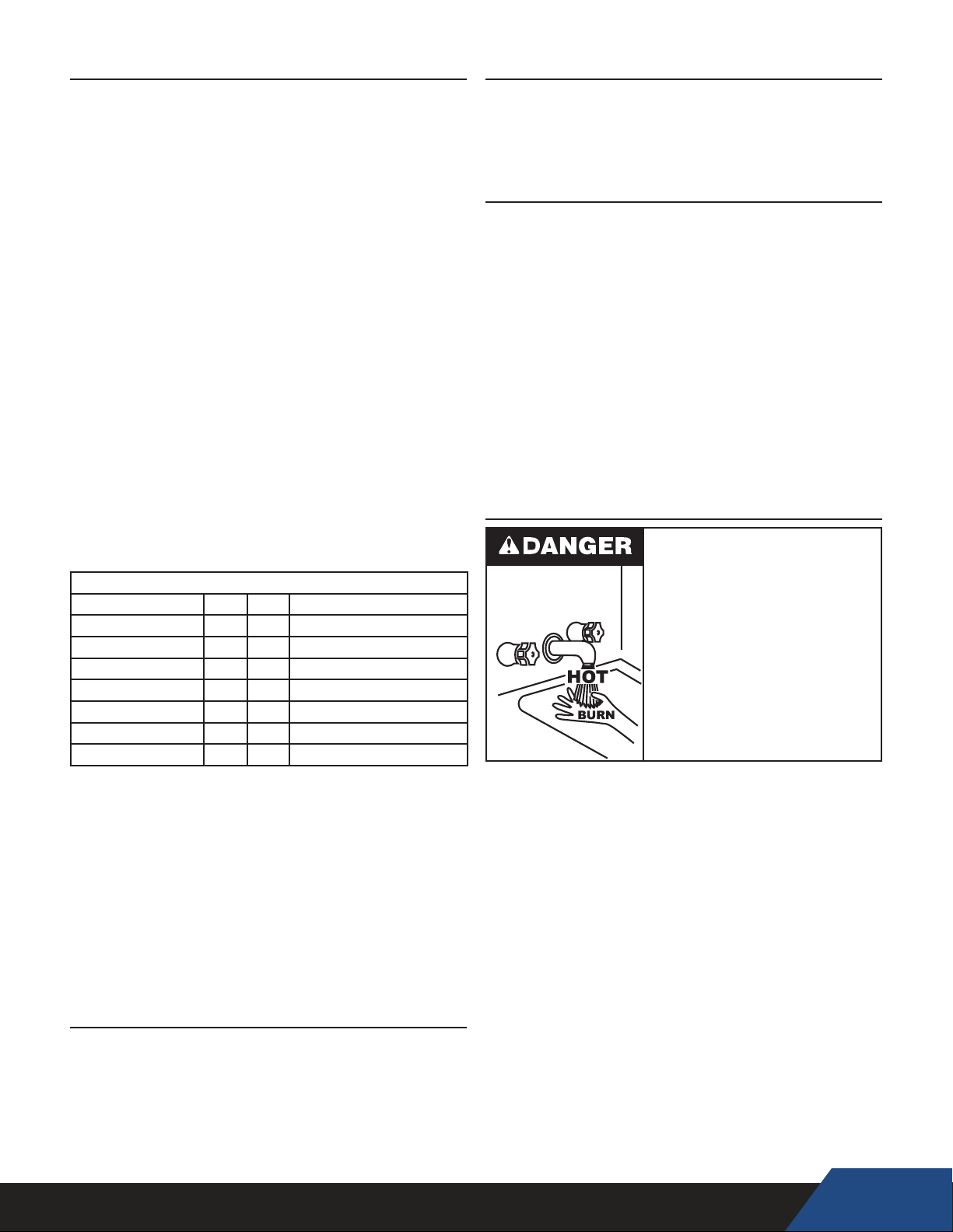
Water temperature over 125°F (52°C)
can cause severe burns instantly
resulting in severe injury or death.
Children, the elderly and the
physically or mentally disabled are at
highest risk for scald injury.
Feel water before bathing or
showering.
Temperature limiting devices such as
mixing valves must be installed
when required by codes and to
ensure safe temperatures at fixtures.
PIPE SUPPORT
All water piping must be properly supported per local code
requirements.
PIPE INSULATION
All piping installed between the HPWH unit and the storage tank
must be insulated.
COLD WATER SUPPLY
Cold water supply lines should not be connected directly to the
HPWH inlet or T tted into the inlet (return) water piping. The cold
water supply lines should be connected directly to the storage
tank only. See Inlet & Outlet Water Temperature on page
11 and Figure 7 and Figure 8 on page 22.
WATER PRESSURE
System water pressure should be maintained between 40 and 60
PSI. Local code may require, and the manufacturer recommends,
installing a pressure reducing valve (PRV) in the cold water
supply to the building to maintain consistent water pressure.
Water heated to a temperature which will satisfy clothes washing,
dish washing, and other sanitizing needs can scald and
cause permanent injury upon contact. See Table 5, page 18.
Some people are more likely to be permanently injured by hot
water than others. These include the elderly, children, the inrm
and the physically/mentally disabled. The Table below shows
the approximate time-to-burn relationship for normal adult skin.
If anyone using hot water provided by the water heater being
installed ts into one of these groups or if there is a local code
or state law requiring a certain water temperature at the point of
use, then special precautions must be taken.
In addition to using the lowest possible temperature setting that
satises the demand of the application a Mixing Valve should be
installed upstream from the building xtures or at the hot water
taps to further reduce system water temperature.
Mixing valves are available at plumbing supply stores. Consult
a Qualied Installer or Service Agency. Follow the mixing valve
manufacturer’s instructions for installation of the valves.
17
Page 18
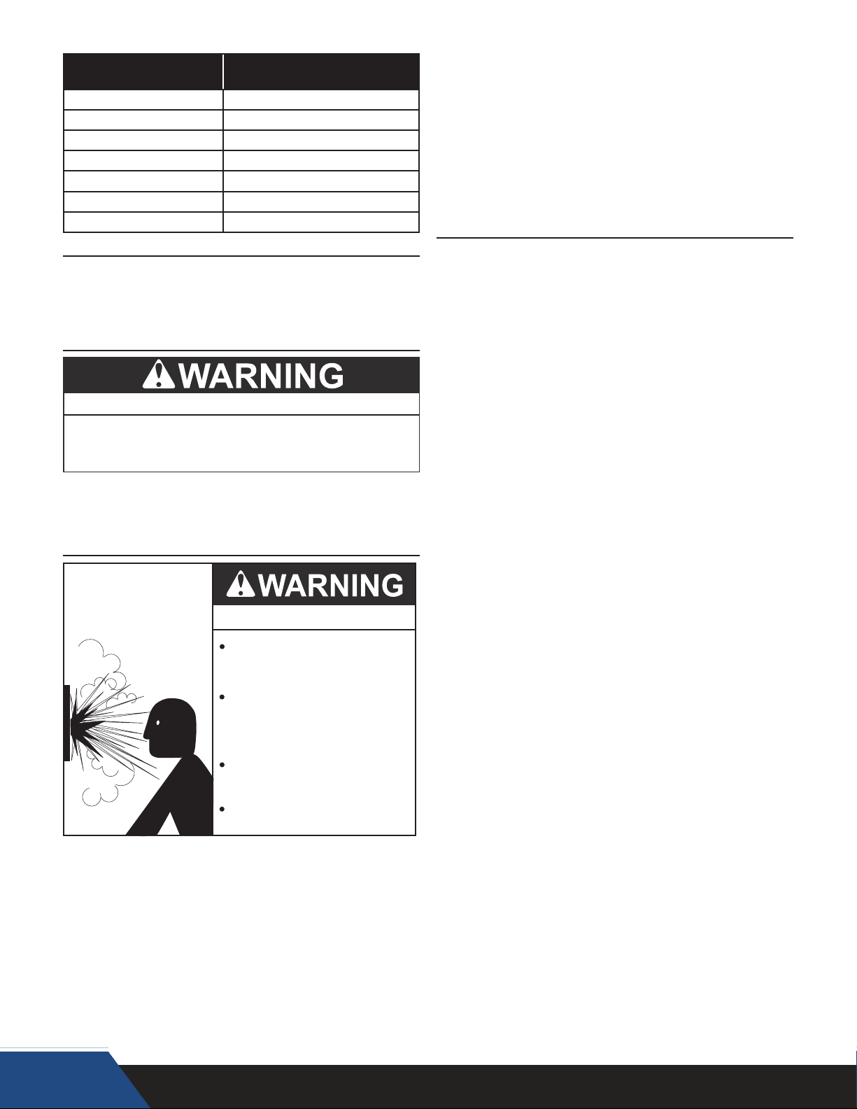
TABLE 5
or greater than the total heating input rating of all water heaters
Water Temperature
180°F (82°C) Nearly instantaneous
170°F (77°C) Nearly instantaneous
160°F (71°C) About 1/2 second
150°F (66°C) About 1-1/2 seconds
140°F (60°C) Less than 5 seconds
130°F (54°C) About 30 seconds
120°F (49°C) More than 5 minutes
Time to Produce 2nd & 3rd
Degree Burns on Adult Skin
CONTAMINATED WATER
Corrosive Chemical Hazard
Connecting the heat pump to any system other than a water
•
system may lead to premature corrosion of the unit's heat
exchanger and void the unit warranty.
This HPWH unit must not be used to heat any uid other than
water. Corrosive chemicals must not be introduced into the
waterways in this HPWH unit.
TEMPERATURE - PRESSURE RELIEF VALVE
Explosion Hazard
Temperature-Pressure Relief Valve
must comply with ANSI Z21.22CSA 4.4 and ASME code.
Properly sized temperaturepressure relief valve must be
installed in the designated
opening in the storage tank.
connected to the storage tank. If more than one water heating
appliance is connected to the storage tank the aggregate total
of all heating input ratings of all connected appliances must be
factored when choosing a T&P valve for the storage tank.
The pressure rating of the T&P valve should always be rated
equal to or below the working pressure rating of the storage tank
or water heater, whichever rating is lower.
Contact the manufacturer of the storage tank for assistance in
sizing of a temperature and pressure relief valve. Follow the
storage tank manufacturer’s instructions regarding the proper
installation of these products.
TANK SELECTION
The HPWH unit is not an instantaneous water heater and must
be connected to a storage tank. Storage tank congurations must
meet these criteria:
1.
The HPWH must not be connected directly to a standard gas
or electric water heater.
If the HPWH is connected to a used storage tank, the tank
2.
should be thoroughly cleaned of scale and sediment before
the HPWH is installed.
Connection ports used on the storage tank must permit the
3.
recommended ow r ate t hrough H PWH. T he connection
ports used on the storage tank must not be smaller than the
inlet outlet connection sizes on the HPWH unit. See Table 4
on page 17.
4. Water heated by the HPWH should be returned to the tank at
a location that is above the level of the tank’s cold water inlet
and/or the heat pump’s inlet source.
5. The HPWH unit’s inlet and outlet lines to the storage tank
should be dedicated. Example: no other line (such as a
building re-circulating loop or cold water supply) should be
connected to the HPWH unit’s inlet or outlet water lines.
SOLAR TANKS
Solar tanks should be used with caution. Some solar tanks with
top connections have dip tubes which may signicantly reduce
the efciency performance of the HPWH unit.
Before using any solar tank in this application, contact your
representative or call the toll free technical support number on
the back cover of this manual for further assistance.
Can result in overheating and
excessive tank pressure.
Can cause serious injury or death.
This heat pump water heater should only be connected to a
storage tank with a properly rated/sized and certied combination
temperature - pressure relief valve. The valve must be certied by
a nationally recognized testing laboratory that maintains periodic
inspection of production of listed equipment of materials as
meeting the requirements for Relief Valves for Hot Water Supply
Systems, ANSI Z21.22 • CSA 4.4, and the code requirements of
ASME.
When the HPWH unit is connected to a storage tank a temperature
and pressure relief valve must be installed in the designated
opening for the T&P valve per the storage tank manufacturer’s
requirements. The T&P valve’s Btu/hr rating must be equal to
18
Page 19
Potentially harmful fumes and vapors could be introduced
into occupied spaces. See Unit Placement on page 18.
STORAGE & HANDLING
HEAVY OBJECT!
All Heat Pump Water Heaters (HPWHs) covered by this manual
are beyond the safe lifting weight for one person. Use
proper conveyance equipment to move the unit for storage
or during installation. Use OSHA approved safety equipment
when moving the unit
The heat pump water heaters covered in this manual are
stationary refrigeration appliances. Careful handling is necessary
to prevent internal damage.
• IMPORTANT: Do not remove, cover or deface any
permanent instructions, wiring diagrams, labels, or the
rating label from the outside cabinet or the inside panels on
the HPWH unit.
• Do not tilt the unit beyond 45° at any time. All internal
components are braced from the base of unit. Tilting may
compromise the refrigeration piping inside unit and cause
refrigerant leaks.
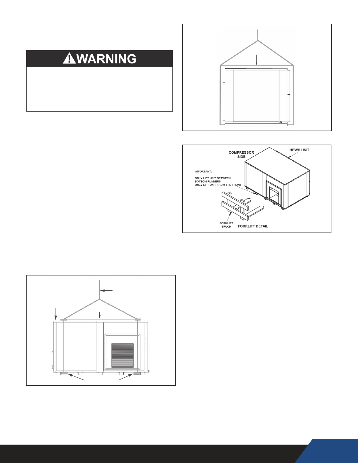
• Do not hoist the unit with chains or straps unless
spreader bars are furnished and used as depicted in
Figure 4 and Figure 5. The side panels and roof of the
unit are not constructed to handle significant force from
the sides or above.
• When using a forklift to raise the HPWH unit ensure the
forks are positioned correctly between the runners on the
bottom of the HPWH unit. See Figure 6.
• The HPWH unit must be lifted from the front side only
when using a forklift to raise the unit. See Figure 6.
COMPRESSOR
SIDE
.
SPREADER
BAR
RIGGING
SPREADER
BAR
SIDE
Figure 5
Figure 6
STORAGE RECOMMENDATIONS
The HPWH units should be stored indoors. Do not stack units or
stack other construction materials on the units while in storage.
The HPWH units contain electrical/electronic components
and should only be stored in conditions between 0ºF to 110°F
(-17°C to 43°C) and 5 to 95 percent relative humidity. Electrical
components are not moisture-tolerant.
NOTE: The limited warranty does not cover damage to the unit or
controls due to negligence during storage.
FRONT
SUPPORT BARS
Figure 4
The pictures may appear different than your actual unit, all information
and reference to lifting applies to all of our models.
,
19
Page 20

INSTALLATION
5. Refrigerant reclamation storage tank.
REQUIRED ABILITY
Installation and service of the HPWH unit requires ability
equivalent to that of a qualied agency i n t he eld involved.
Plumbing, ducting and electrical work are
required. See Qualifications on page 10.
GENERAL
The installation must conform with these instructions and the
local code authority having jurisdiction. In the absence of local
codes, the installation must comply with the latest editions of
the National Electrical Code, ANSI/NFPA 70 or the Canadian
Electrical Code CSA C22.1. The National Electrical Code
may be ordered from: National Fire Protection Association, 1
Batterymarch Park, Quincy, MA 02269. The Canadian Electrical
Code is available from the Canadian Standards Association,
8501 East Pleasant Valley Road, Cleveland, OH 44131.
DO NOT start the HPWH unit or test the electrical system before
it is connected to the water system, purged of air and filled with
water. See Start Up on page 25.
See Features And Components on page 12 to identify
the principal components of the HPWH. (Some units will vary)
REQUIRED TOOLS AND MATERIALS
INSTALLATION & START UP TOOLS
1. All tools common to installation and service of commercial
electric water heaters such as hand tools, pipe cutter and
torch.
2. Heat transfer compound (paste) such as Honeywell part
number 107408 or equivalent.
3. Electrical switch lock out device - used to secure disconnect
switches/breaker panels while servicing.
4. Electronic thermometer including:
• Four (4) thermocouple sensors capable of measuring
surface temperatures on water or refrigerant piping up to
2 inch diameter.
• Temperature range 32°F - 210°F (0°C - 100°C).
5. Volt-Ohm Multi Meter - capable of measuring:
• AC Voltage up to 600 VAC.
• DC Voltage up to 24 VDC.
• Ohms up to 2,000,000 ohms.
• Continuity.
6. AC amp meter - capable of measuring:
• AC amperage up to 200 amps.
7. Calculator.
SERVICE TOOLS
UNIT PLACEMENT
Whether replacing existing water heating equipment or installing
the HPWH in new construction, the following critical points must
be observed: The HPWH unit:
1. Should be installed near a floor drain for condensate removal.
2. The HPWH, storage tank and water heater(s) should be
located in an area where leakage will not result in damage
to adjacent area or to lower floors in the building structure.
3. The HPWH unit must be level for proper condensate
drainage. Shim the channel type skid base, pad or floor as
necessary if levelling is required.
4. Should be installed close to the point of major hot water
usage and power supply.
5. Should be located so that hot water piping and branch circuit
wiring will be as short as possible.
Mounting Frame
The mounting frame must support the length, width, and weight
of the HPWH unit. The weight of the HPWH unit must be evenly
dispersed across the footing channels on the bottom of the unit.
See Table 1 on page 13 for unit dimensions and weights.
1. VIBRATION ISOLATORS ARE REQUIRED to prevent
transmission of mechanical vibration into the building
structure. Selection of suitable isolators should be made by a
qualified engineer.
2. Installation must meet local seismic restraint requirements.
PAD MOUNTING
The HPWH may be pad mounted. Vibration isolator mounts
MUST BE placed between the unit and the equipment pad to
prevent mechanical vibration transmitting into the building
structure. Selection of appropriate vibration isolators should be
made by a qualified engineer.
See Qualifications on page 10 regarding regulations
and certifications required under Section 608 of the Clean Air
Act before servicing the refrigeration circuit.
1. Refrigeration manifold gauges.
2. Refrigeration charging scale.
3. Refrigeration vacuum pump.
4. Refrigerant recovery machine.
20
Page 21
ELECTRICAL CONNECTIONS
CAUTION
CORRECT POWER SUPPLY!
Ensure the power supply at the job site matches the
•
voltage and phase listed on the HPWH rating label
before connecting power to the HPWH unit.
Energizing the HPWH with the wrong voltage or phase
•
will cause permanent damage to the HPWH unit.
Damage caused to the HPWH as the result of applying
•
the wrong voltage or phase is not covered under the
limited warranty.
CORRECT VOLTAGE AND PHASE
The HPWH units covered by this instruction manual can
be ordered with multiple power supply voltage and phase
congurations. Ensure the power supply voltage and phase
at the job site matches the power supply ratings listed on the
HPWH rating label BEFORE INSTALLATION BEGINS.
Voltage applied to the HPWH should not vary more than +5% to
-10% of the voltage requirement listed on the HPWH rating label
for satisfactory operation.
Energizing the HPWH with the wrong voltage and/or phase may
cause permanent damage to HPWH components. Damage
resulting from applying the wrong power supply voltage or phase
to the HPWH is not covered under the limited warranty.
Electrical Shock Hazard
Before removing any access panels or
•
servicing the water heater, make sure
the electrical supply to the water heater
is turned “OFF.”
Failure to do this could result in death,
•
serious bodily injury, or property
damage.
BRANCH CIRCUIT DISCONNECT SWITCH
The power supply wiring and equipment grounding must be
installed in accordance with local codes or, in the absence of
local codes, the National Electrical Code, ANSI/NFPA 70 or the
Canadian Electrical Code, CSA C22.1.
Install an adequately fused disconnect switch as close to the unit
as possible. See unit rating label for maximum fuse size (MFS).
Run the power supply lines from the disconnect to the control
box at the front panel of the unit. Connect the lines to the
terminals on
three phases. Connect ground wire to ground lug.
See Minimum Circuit Ampacity & Maximum Fuse Size on page
15 for wire, fuse and breaker sizing information.
input side of power distribution block L1, L2 & L3 for
WATER CONNECTIONS
Water piping must be installed in accordance with the instructions
in this manual and all local plumbing codes having jurisdiction.
See Figure 7 and Figure 8 on page 22 and the Piping Diagrams
starting on page 35 as a reference for these instructions.
INSTALLATION INSTRUCTIONS
1. This HPWH unit is not designed to supply hot water directly
to hot water fixtures. The HPWH unit must be installed with a
separate storage tank as shown in the water piping diagrams
in this instruction manual.
2. Water lines installed between the storage tank and the HPWH
unit MUST NOT be less than the water pipe connection sizes
on the unit. See Table 4 on page 17.
3. The HPWH should be plumbed directly to the storage tank.
4. The cold water supply must be connected directly to the
storage tank at a low connection port on the storage tank
on single tank and two tank preheat piping configurations for
optimal efficiency. See Figure 7 and Figure 8 on page 22.
5. The cold water supply MUST NOT be connected the inlet
(entering/return) water line to the HPWH unit.
6. The outlet (supply) water from the HPWH unit should connect
to a middle or lower port on the storage tank.
7.
The inlet (return) water from the HPWH unit should connect
to a port on the storage tank lower than the outlet.
A heat trap should be installed between the storage tank and
8.
the backup water heater on two tank preheat systems. See
Piping Diagram starting on page 35.
A T&P valve must be installed in the designated opening on
9.
the storage tank per the tank manufacturer’s requirements.
10. For optimal performance minimize the equivalent length of
water piping between the HPWH and storage tank.
11. Building hot water recirculation loop should be connected to
the inlet of the backup water heater on two tank preheat
configurations or to the storage tank on single tank
configurations. The recirculating pump MUST BE controlled
by a field supplied thermostat installed in the building
recirculation return line near the storage tank or back up
heater. The thermostat should stop pump operation the
moment the recirculation line is hot.
12. Use swing-type check valves (not spring-loaded types) on
the water outlet lines of all HPWH units plumbed in parallel to
prevent hot water short-circuiting.
13. Water lines shared by parallel HPWH units must be large
enough to handle combined water flows. A manifold as well
as balancing valves and solenoids are required. Flow rates
through the heat pumps and tank(s) must be balanced. See
Table 1 on page 13 for HPWH unit flow rates.
21
Page 22
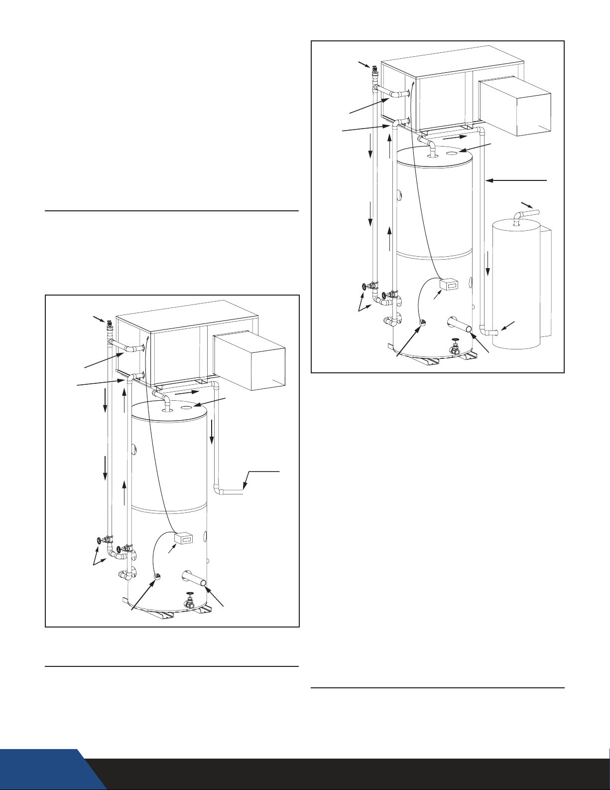
15. All components in the hot water supply system must be
TANK THERMOSTAT
TANK THERMOSTAT
adequately sized to meet peak water ow requirement
16. When the HPWH unit is installed above the storage tank
install a Tee tting at a high point in the outlet water line
leaving the unit. Install a purge valve, or if required by local
code, a T&P valve (temperature and pressure relief) in a
branch of the Tee tting that can be used to purge air from
the HPWH unit during start up. See Figure 7 and Figure 8.
17. DO NOT install a (T&P) relief valve in the outlet line of the
HPWH unit unless required by local code.
18. Dielectric unions should be installed at the inlet and
outlet water lines to the HPWH unit.
19. All HPWH water piping must be insulated.
SINGLE TANK CONFIGURATION
The HPWH must be plumbed to storage tank. The maximum
stored water temperature the HPWH unit can produce in the
storage tank is 150°F (66°C). Figure 7 shows a typical storage
tank piping conguration. Tank p orts m ust be l arge e nough to
handle the peak water flow rates through the water heating
system. See Piping Diagrams startingon page 35 for detailed
piping diagrams.
Purge Valve or T&P
(purge air from system)
Purge Valve or T&P
(purge air from system)
OUTLET
(SUPPLY)
INLET
(RETURN)
ISOLATION
VALVES
HPWH
STORAGE
TANK
DIGITAL TA NK
THERMOSTAT
SUPPLY
T&P VALV E
OPENING
PRE-HEATED
WATER OUT
HOT
OUTLET
BACKUP
WATER
HEATER
(OPTIONAL)
PRE HEATED
WATER INLET
DUCT
OUTLET
(SUPPLY)
INLET
(RETURN)
ISOLATION
VALVES
REMOTE TEMPERATURE
SENSOR OR MECHANICAL
HPWH
STORAGE
TANK
DIGITAL TA NK
THERMOSTAT
Figure 7
T&P VALV E
OPENING
COLD
INLET
SUPPLY
DUCT
HOT
OUTLET
REMOTE TEMPERATURE
SENSOR OR MECHANICAL
COLD
INLET
Figure 8
You individual HWP design may vary, Air Source as opposed to
Individual HPWH deigns may vary. (Air source as opposed
to water source.) The same heated water piping design will
Water Source. The same heated water piping design will apply.
apply.
HPWH
UNIT
When water temperatures above 150°F (66°C) are required the
HPWH and storage tank are piped in series (upstream) with a
backup water heater. See Water Temperature on page 14. The
backup water heater will raise the temperature of the preheated
water to the nal system temperature required. Figure 8 shows a
typical preheat piping conguration.
22
MULTIPLE TANK PRE HEAT CONFIGURATION
Figure 9
STANDARD TANK THERMOSTAT
Standard tank thermostats (Aquastat) already installed in the
storage tank may be used instead of the factory supplied Digital
Tank Thermostat if desired. Ensure the standard tank thermostat
is installed the lower third of the tank. Wire the existing
tank thermostat to the HPWH terminal strip.
Page 23
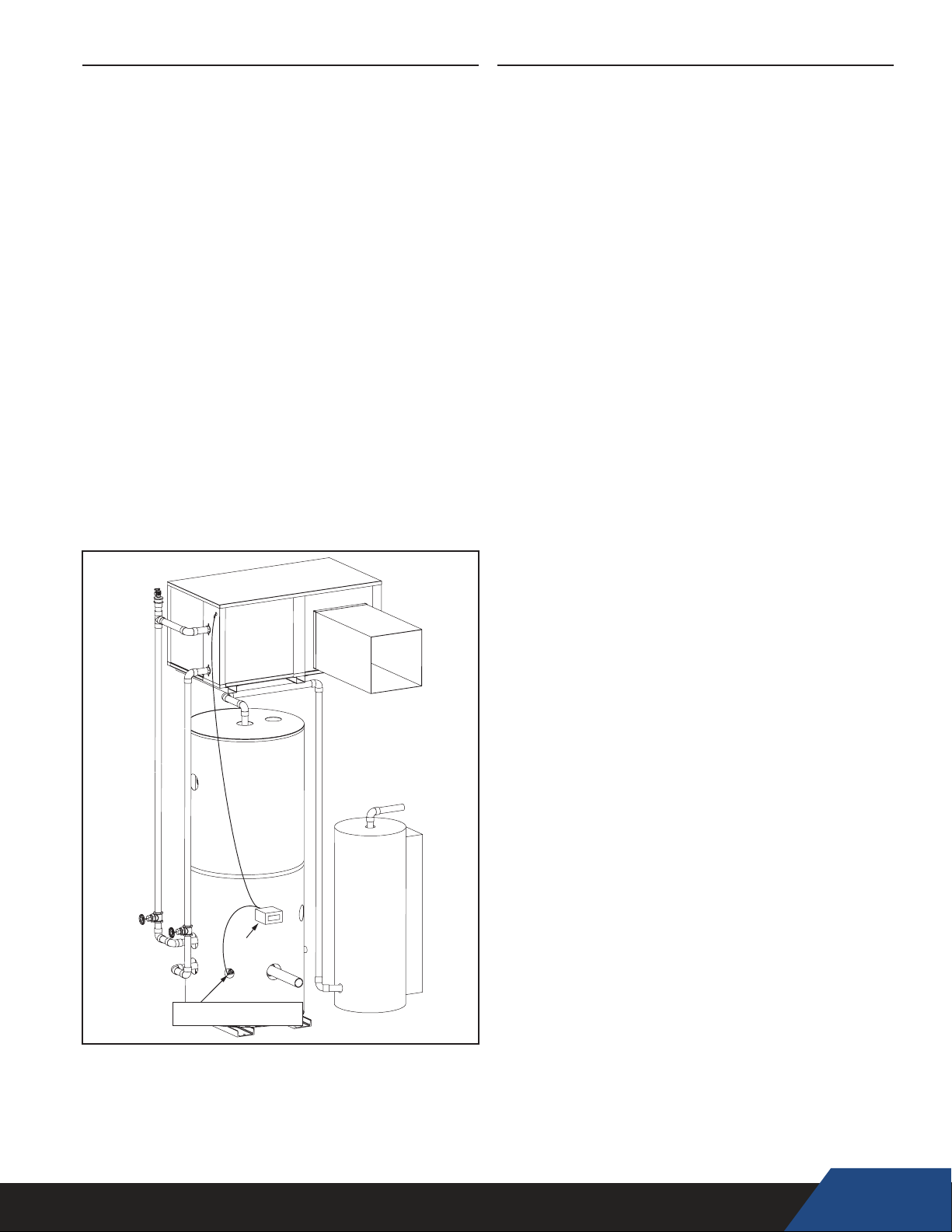
TEMPERATURE SENSOR INSTALLATION
The HPWH unit is shipped from the factory with a Digital
Tank Thermostat that includes a Temperature Sensor:
,
1. Secure the Temperature Sensor inside a Sensor or Thermal
Well .
Install the sensor well in the storage tank’s designated
temperature control opening. It is not recommended to
install the temperature probe or sensor in the bottom or the
top of the tank. It is typical to install in the mid to lower
portion of the tank.
Do not install the temperature sensor near the cold water supply
connection to the storage tank to prevent short cycling.
Breathing Hazard - Carbon Monoxide Gas
Do not duct air from a garage or other
space where potentially harmful fumes
from solvents, chemicals or exhaust
from automobiles are present into any
other space in the building structure.
Gas and carbon monoxide detectors
are available.
Breathing carbon monoxide can cause brain damage or
death. Always read and understand instruction manual.
.
HPWH
STORAGE
TANK
REMOTE TEMPERATURE
SENSOR
Figure 10
BACKUP
WATER
HEATER
23
Page 24

INSTALLATION CHECKLIST
The list below represents some of the most critical installation
requirements that, when overlooked, often result in operational
problems, down time and needless parts replacement. This
is not a complete list. Before performing any troubleshooting
procedures use the list below to check for installation errors.
Costs to correct installation errors are not covered under the
limited warranty. Ensure all installation requirements and
instructions in this manual have been followed.
LOCATION
1. Ensure the HPWH is located where there is a adequate
supply of ambient heat for optimal performance or that the
HPWH is ducted to such a location.
2. Ensure required clearances are maintained and there is
access for servicing. See Clearances on page 13.
WATER PIPING
7. Ensure the outlet (supply) and inlet (return) water piping
3.
connected to the HPWH are not less than the connection
size on the unit. See Table 1 on page 13.
4.
8. When the HPWH is connected to a storage tank ensure the
storage tank is equipped with a properly rated and sized
Temperature and Pressure (T&P) relief valve. Refer to the
storage tank manufacturer’s instructions for T&P valve sizing
and installation requirements.
NOTE: This is a critical installation requirement that must
not be overlooked.
5.
9. DO NOT install a T&P valve in the outlet (supply) water line
of the HPWH unless required by local code.
6. Ensure isolation valves are installed on the HPWH supply
and return water line at the storage tank for servicing and
purging the air from the HPWH during start-up.
7. Ensure the cold water supply is not connected directly to or
Tee fitted to the inlet water line on the HPWH. See the Service
and Installation Notes for Inlet & Outlet Water Temperature
on page 12. See Figure 7 and Figure 8 on page 22.
15. Connect building recirculation loop piping to the backup
8.
water heater/storage inlet on multi tank preheat piping
configurations.
16. Ensure the building recirculation loop pump is controlled by a
9.
field supplied line thermostat and that it stops the pump when
the recirculation line is hot. Your particular system may use
the included PLC to control the pump as well.
10.
17. When the HPWH unit is installed "above" the storage
tank install a Tee fitting at a high point in the outlet water line
with a purge valve to bleed air during start up.
18. Though not required, the manufacturer recommends
11.
installing a strainer at the inlet water line on the HPWH to help
prevent scale build up in the heat exchanger. Service costs to
clear blockages from the HPWH unit’s heat exchanger due to
debris are not covered under the limited warranty.
ELECTRICAL
12.
21. BEFORE ENERGIZING THE UNIT ensure the power supply
voltage and phase matches the requirements on the HPWH
rating label. Damage resulting from applying the wrong
voltage or phase is not covered under the limited warranty.
13.
22. Ensure the power supply breaker or the fuses disconnect
switch are within the requirements for the unit as shown on
the HPWH rating label.
14.
23. Ensure the power supply wiring meets the MCA (Minimum
Circuit Ampacity) requirements shown in this manual and on
the HPWH data label.
15.
24. Ensure the HPWH is properly grounded according to the
instructions in this manual and local code requirements.
25. Ensure the power supply connections to the HPWH are
16.
connected properly and securely tightened.
26. Ensure all electrical connections in the HPWH control panel
17.
are securely tightened.
18.
27. When the factory supplied Temperature sensor is used:
• Insure the sensor is installed properly.
• Ensure the Temperature Sensor has been installed in a
designated temperature control opening in the mid/lower
portion of the storage tank.
• Ensure the supplied Temperature Sensor is coated with a
suitable heat transfer compound (paste).
24
Page 25
Pre-Startup Checklist
1. Before applying power, check all electrical connections. Tighten if necessary.
2. Verify electrical installation. Power requirements and branch circuit disconnecting
means match equipment nameplate specifications.
3. Make sure the hydronic system is flushed and purged of air. Remove and clean any
strainers or filters if necessary.
4. Make sure the sensor for the temperature control is mounted to either the water tank
or strapped to a water line for proper temperature control.
5. Remove the shipping blocks from under the compressor. Loosen the nuts on the spring
mounting studs and pry up one side of the compressor at a time and remove. Leave the
nuts loose on the spring mounting studs.
6. Power up circulator pump and verify water flow through the heat pump heat
exchanger(s).
7. Apply power to the heat pump. Confirm power with an electrical meter. Check for
proper control power, should be between 120 to 125 volts. *Note: The control power
should be on for 4 to 6 hours so the compressor crankcase heater has time to warm
up the base of the compressor.
8. Start the heat pump by pressing the Start key on the Touchscreen. Go to the INFO
screen and monitor the refrigerant pressures, hot water in and out temperatures and
cold water in and out temperatures.
9. There are Fan, (or Blower, if so equipped), Direction stickers, mounted on each unit.
It may be helpful to record the operating data initially every 10 to 15
minutes just to see how the heat pump is performing.
Unit 2
Unit 1
25
Page 26
3 Phase Startup Procedures
Make sure the disconnect is off and confirm there is no power on the distribution block on the
electrical panel.
Pull Compressor fuses.
Trip the blower/fan motor starter.
Turn power on. Check and make sure the power at the distribution block is the same as the
power requirements on the data sticker that is on the electrical panel.
Put an amp meter on one of the legs for the blower/fan motor. Confirm the amperage is in line
with the data sticker.
Reset the manual motor starter for the blower/fan.
Make sure the blower/fan is going in the correct direction. (Should be blowing air at you when
you're standing in front of it)
If it is going the wrong direction, then you need to switch the phases. You will need to switch
the phases that you supplied to the distribution block. The rotation on the blower/fan is rotating
the same direction as the compressor, that was set at the factor. So, if the blower/fan is
operating in the correct direction then your compressor is as well. Make sure to turn the power
off before switching the phase. Confirm there is no power with an electrical meter then make
the switch. Turn the blower/fan motor start off and then turn the power back on. Check for
power and then turn the blower/fan motor starter back on and record the amperage. Confirm
the rotation is correct.
The factory temp setting is 125°F. If you would like to change the temperature, then now is the
(It can be done later as well).
time.
Turn power off.
Double check to make sure all the air is out of the water line so the heat pump doesn't get air
bound.
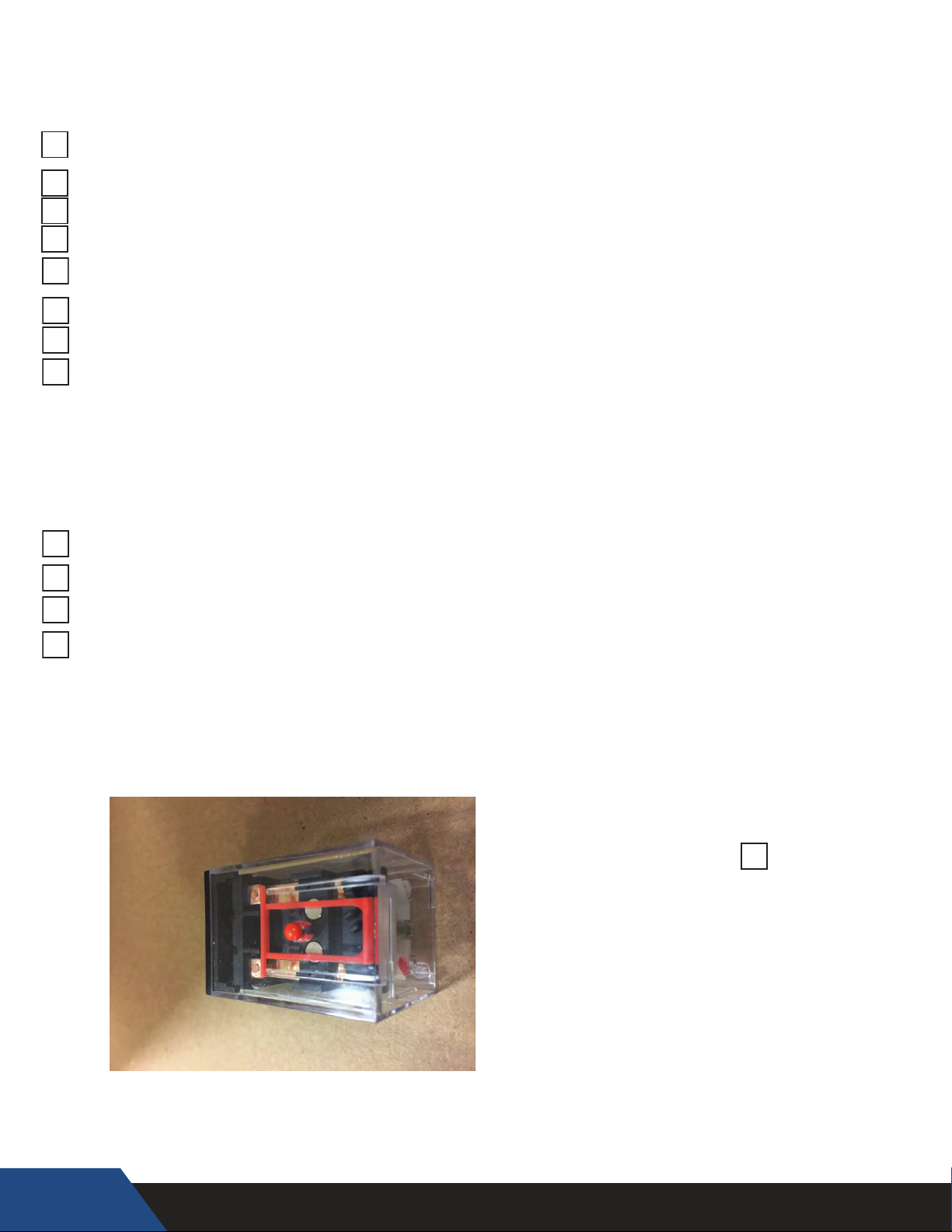
Pump Test – With the compressor fuses pulled and the blower/fan motor starter in the off,
(tripped), position. Turn the power back on. See figure #1 below. Press the orange by-pass
button on the pump relay to operate the water pump. You should be able to hear the water
flowing through the system. If not, there is a good chance the system is air bound and the air
needs to be removed before starting the compressor. Turn power back off after test.
26
Figure #1
Commissioning Complete:
Signature: ___________________________
Page 27

Initial Start-Up
CAUTION OIL DILUTION! Bearing malfunction! It is important to ensure that new compressors are not subjected
to liquid abuse. Turn the crankcase heater on 6 hours before starting the compressor. CAUTION High discharge
pressure operation! Compressor damage! Do not use compressor to test opening set point of high-pressure cutout. Bearings are susceptible to damage before they have had several hours of normal running in. Liquid and high
pressure loads could be detrimental to new bearings. It is therefore important to ensure that new compressors
are not subjected to liquid abuse and high-pressure run tests. It is not good practice to use the compressor to test
the high-pressure switch function on the production line. Switch function can be tested with nitrogen prior to
installation and wiring can be checked by disconnecting the high-pressure switch during the run test.
Rotation Direction
Scroll compressors, like several other types of compressors, will only compress in one rotational direction.
Direction of rotation is not an issue with single-phase compressors since they will always start and run in the
proper direction. Three-phase compressors will rotate in either direction depending upon phasing of the power
to L1, L2 and L3. Since there is a 50/50 chance of connecting power in such a way as to cause rotation in the
reverse direction, it is important to include notices and instructions in appropriate locations on the equipment to
ensure proper rotation direction is achieved when the system is installed and operated. Observing that suction
pressure drops and discharge pressure rises when the compressor is energized allows verification of proper
rotation direction. There is no negative impact on durability caused by operating three-phase Copeland Scroll™
compressors in the reversed direction for a short period of time, (under one hour), but oil may be lost. Oil loss
can be prevented during reverse rotation if the tubing is routed at least 15 cm above the compressor. After
several minutes of operation in reverse, the compressor protection system will trip due to high motor
temperature. The operator will notice a lack of cooling. However, if allowed to repeatedly restart and run in
reverse without correcting the situation, the compressor will be permanently damaged. All three-phase Scroll
compressors are identically wired internally.
Therefore, once the correct phasing is determined for a specific system or installation, connecting properly
phased power leads to the identified compressor terminals will ensure proper rotation direction. Compressors
ZB56K* to ZB220K*, ZS56K* to ZS11M* and ZF24K* to ZF48K* have an electronic protection unit (INT69SCY2)
that will not let the compressor operate if the phasing of the wires is incorrect.
Starting Sound
During the very brief start-up, a clicking sound is audible, resulting from initial contacting of the spirals and is
normal. No start assist devices are required for single-phase compressors, even if a system uses non-bleed
expansion valves. Due to the design of the Copeland Scroll, the internal compression components always start
unloaded even if system pressures are not balanced. In addition, since internal compressor pressures are always
balanced at start-up, low voltage starting characteristics are excellent for Copeland Scroll™ compressors.
Moreover, if low voltage conditions exist at start up, protector trips could result.
27
Page 28

Start Up Check List
START UP
flow is decreased the temperature rise will increase and as
water flow is increased the temperature rise will decrease.
Because of this relationship between temperature rise and
flow rate this test can be useful to determine if the flow rate
through the heat exchanger is adequate. Other factors may
also affect water flow rate and temperature rise such as
debris or lime scale build up inside heat exchanger or water
pump operation.
If the temperature rise through the HPWH is
consistently lower than 8°F the outlet (supply) valve can
be throttled slightly closed to reduce the water flow rate.
This may be necessary on installations with a minimum of
water piping between the HPWH and the water system or
tank.
Throttling should be done in small increments, no more than
1/8 turn of the valve handle at a time. The HPWH must be
allowed to run for approximately 5 minutes between each
adjustment before the temperature rise is measured again.
If the outlet valve is throttled during start up, mark the valve
position and remove the valve handle to ensure it is not
accidentally changed.
If the temperature rise through the HPWH is consistently
greater than 12°F the water flow may be restricted. Ensure
all water valves between the HPWH and the tank or water
system are fully open. Ensure the external water
pump is running. If the temperature rise continues
to be excessive call the toll free technical support phone
number: 1-800-777-6953 ext. 208
5. Using thermometers or temperature sensors, measure the
temperature of the incoming source water to the HPWH
and the outgoing source water leaving the unit. The outgoing
temperature should be 12°F to 20°F (7°C to 13°C) cooler
than the incoming. The higher the flow rate the lower the
temperature differential will be.
6. When all of the above procedures are complete, adjust
the tank temperature control set point to desired system
temperature, not to exceed 150°F (66°C). Remove all test
instruments and replace all cabinet doors.
This start-up refers to several tools and test instruments needed
to complete the procedure. See Required Tools and Materials
on page 18.
Turn off power to the water heater
before performing any service.
Electrical Shock Hazard
•
Label all wires prior to disconnecting
when performing service. Wiring errors
can cause improper and dangerous
operation.
•
Verify proper operation after servicing.
•
Failure to follow these instructions can
result in personal injury or death.
•
1. Ensure the Installation Checklist has been completed.
2. Ensure the HPWH, storage tank and water system has been
purged of air and all valves are in the position for normal
operation.
3. Turn on power at the circuit breaker or disconnect switch
serving the HPWH.
If the HPWH does not start immediately:
• Wait 5 minutes in case the anti short cycle timer has halted
operation. This control system feature protects the HPWH
from rapid short cycling that can cause permanent
damage to the unit.
• Ensure the operating set point on the tank temperature
control is adjusted high enough to initiate a call for heat.
The recommended setting is 120°F to 150°F (29°C to 66°
C).
• DO NOT set the operating set point on the tank
temperature control above 150°F. See Water Temperature
Range on page 11.
• Ensure the Differential Set Point is not set too high. Higher
differential settings will cause greater temperature swings
in system temperature. Lower differential settings can
cause unit short cycling. The recommended setting is 10°F.
• If the unit does not start after all of the above procedures
have been followed. Refer to the troubleshooting section
of this manual.
4. Securely attach surface mount thermometers or temperature
sensors to the inlet (entering) and outlet (leaving) water lines
near the HPWH cabinet. If there are thermometers installed
in the inlet and outlet in close proximity to the HPWH water
connections they can be used for the following check. Ensure
the water outlet (supply) and inlet (return) valves are fully
open. Start the HPWH and allow it to operate for 5 minutes.
With the HPWH operating record the inlet and outlet
temperatures.
During normal operation, the outlet line should be 8°F to 12°F
(4°C to 7°C) hotter than the inlet line. This is the temperature
rise through the heat exchanger inside the HPWH unit. Note:
Temperature rise and water flow rate through the heat
exchanger inside the HPWH are uniformly linked. As water
Job#_______________Model#___________________Ser#__________________ Date_______
1. Check all wire connections for tightness: OK? □
2. Verify correct voltage
3. Verify water flow rates
4. Run unit at 100% capacity for a minimum of 15 min. OK? □
5. Supply (condenser) water temp. in (Tcondin)__________°F
6. Supply (condenser) water temp. out (Tcondout)__________°F
7. Heating Capacity__________btuh
8. Source (evaporator) water temp. in (Tevapin)__________°F (Only applicable to Water Source Units)
9. Source (evaporator) water temp. out (Tevapout)__________°F (Only applicable to Water Source Units)
10. Compressor amps per phase
11. Superheat measured prior to accumulator ________°F
12. Sightglass circuit 1: Clear? □ Bubbles? □
13. Evaporator Pressure _____________psig
14. Condenser Pressure _____________psig
15. Compressor Discharge Line Temperature ________°F
16. Refrigerant Liquid Line Temperature ________°F
17. Oil Level Sight Glass compressor Full□ ¾□ ½□ ¼□
18. Approach Temperature (SCT – Tcondout )___________ °F
Signature________________________ Print Name___________________________
28
Voltage = ________VAC
Evap. Flow________gpm Cond. Flow________gpm
Heating Capacity = (Tcondout – Tcondin) X Cond. Flow X 500
Ph1__________ amps Ph2 __________amps Ph3 __________amps
Saturated Evaporator Temperature (SET)______°F
Saturated Condenser Temperature (SCT)________°F
Page 29
START UP
This start-up refers to several tools and test instruments needed
to complete the procedure. See Required Tools and Materials
on page 18.
Electrical Shock Hazard
Turn off power to the water heater
•
before performing any service.
Label all wires prior to disconnecting
•
when performing service. Wiring errors
can cause improper and dangerous
operation.
Verify proper operation after servicing.
•
Failure to follow these instructions can
•
result in personal injury or death.
1. Ensure the Installation Checklist has been completed.
2. Ensure the HPWH, storage tank and water system has been
purged of air and all valves are in the position for normal
operation.
3. Turn on power at the circuit breaker or disconnect switch
serving the HPWH.
If the HPWH does not start immediately:
• Wait 5 minutes in case the anti short cycle timer has halted
operation. This control system feature protects the HPWH
from rapid short cycling that can cause permanent
damage to the unit.
• Ensure the operating set point on the tank temperature
control is adjusted high enough to initiate a call for heat.
The recommended setting is 120°F to 150°F (29°C to 66°
C).
• DO NOT set the operating set point on the tank
temperature control above 150°F. See Water Temperature
Range on page 11.
• Ensure the Differential Set Point is not set too high. Higher
differential settings will cause greater temperature swings
in system temperature. Lower differential settings can
cause unit short cycling. The recommended setting is 10°F.
• If the unit does not start after all of the above procedures
have been followed. Refer to the troubleshooting section
of this manual.
4. Securely attach surface mount thermometers or temperature
sensors to the inlet (entering) and outlet (leaving) water lines
near the HPWH cabinet. If there are thermometers installed
in the inlet and outlet in close proximity to the HPWH water
connections they can be used for the following check. Ensure
the water outlet (supply) and inlet (return) valves are fully
open. Start the HPWH and allow it to operate for 5 minutes.
With the HPWH operating record the inlet and outlet
temperatures.
During normal operation, the outlet line should be 8°F to 12°F
(4°C to 7°C) hotter than the inlet line. This is the temperature
rise through the heat exchanger inside the HPWH unit. Note:
Temperature rise and water flow rate through the heat
exchanger inside the HPWH are uniformly linked. As water
flow is decreased the temperature rise will increase and as
water flow is increased the temperature rise will decrease.
Because of this relationship between temperature rise and
flow rate this test can be useful to determine if the flow rate
through the heat exchanger is adequate. Other factors may
also affect water flow rate and temperature rise such as
debris or lime scale build up inside heat exchanger or water
pump operation.
If the temperature rise through the HPWH is
consistently lower than 8°F the outlet (supply) valve can
be throttled slightly closed to reduce the water flow rate.
This may be necessary on installations with a minimum of
water piping between the HPWH and the water system or
tank.
Throttling should be done in small increments, no more than
1/8 turn of the valve handle at a time. The HPWH must be
allowed to run for approximately 5 minutes between each
adjustment before the temperature rise is measured again.
If the outlet valve is throttled during start up, mark the valve
position and remove the valve handle to ensure it is not
accidentally changed.
If the temperature rise through the HPWH is consistently
greater than 12°F the water flow may be restricted. Ensure
all water valves between the HPWH and the tank or water
system are fully open. Ensure the external water
pump is running. If the temperature rise continues
to be excessive call the toll free technical support phone
number: 1-800-777-6953 ext. 208
5. Using thermometers or temperature sensors, measure the
temperature of the incoming source water to the HPWH
and the outgoing source water leaving the unit. The outgoing
temperature should be 12°F to 20°F (7°C to 13°C) cooler
than the incoming. The higher the flow rate the lower the
temperature differential will be.
6. When all of the above procedures are complete, adjust
the tank temperature control set point to desired system
temperature, not to exceed 150°F (66°C). Remove all test
instruments and replace all cabinet doors.
29
Page 30
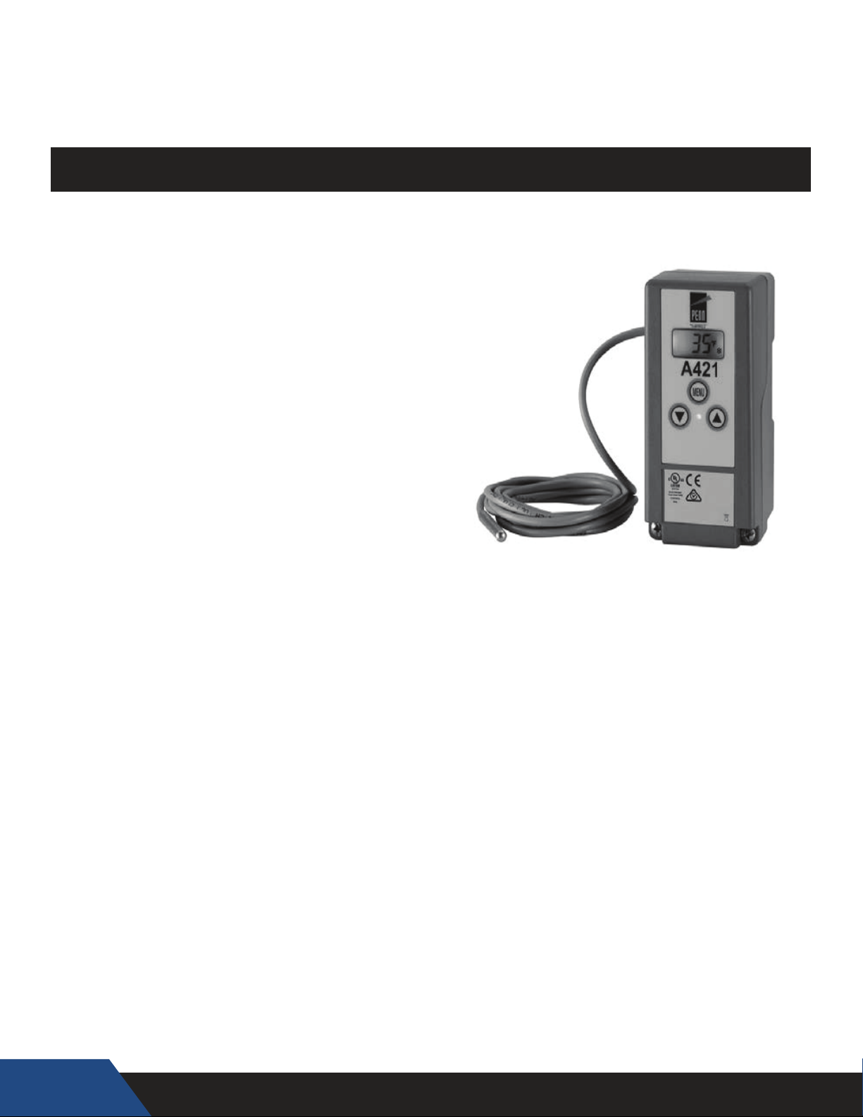
ELECTRONIC TEMPERATURE CONTROLS
CONTROLLER
The Geyser C-series comes standard with a Johnson
Controls A421 Model # A421GBF-x controller. This
control is used to control the water temperature in the
tank by supplying a call signal to the Heat Pump Water
Heater. The control comes with some factory settings.
The A421 control should never be set higher
than 150°F, failure to comply could void the
warranty.
Johnson Controls A421 Controller
Model # A421GBF-x
Notice: Please make sure you are running a Johnson controller
(pictured above) before you continue to the next page. If you
are running a PLC (Programmable Logic Controller) skip to the
directions starting on page 38.
33.
30
Page 31
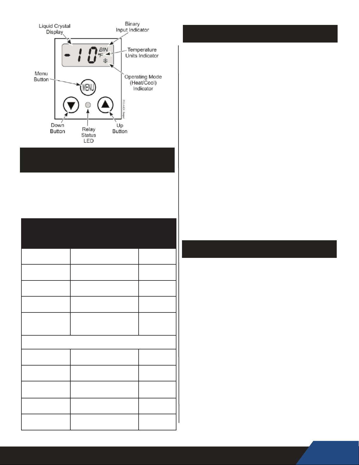
FUNCTION RANGES &
the OFF value again.
SCREEN NAVIGATION
The A421 control buttons and display operate
the same in both Basic and Advanced mode.
• When in Menu screens the parameters and
values will ash on and off.
• Use the Arrow keys to navigate through all of
the parameters and values
• To select a parameter press MENU
• To save a selected value, press MENU.
This will automatically bring you to the next
settable parameter
• To exit menus and return to the main screen
press both arrow keys simultaneously.
SETTINGS
Some of the A421 controllers settings are
preprogrammed by Nyle before shipment. These
settings along with parameter ranges have been
provided for your reference in the Parameter
Settings table below.
PARAMETER SETTINGS
FUNCTION RANGE
OFF: Desired
Temp Hi
On: Desired
Temp Low
ASd: Anti-short
Cycle Delay
SF: Sensor
Failure
bLL: Back light
Level
ADVANCED PARAMETER SETTINGS
Un: Temp.
Units
tSb: Temp.
Setback
So: Sensor
Offset
HtS: High
Temp. Stop
LtS: Low Temp.
Stop
-40 to 212 °F
-40 to 100 °C
-40 to 212 °F
-40 to 100 °C
0 - 12 Min 0 min
0= Output De-energized
1= Output Energized
0 = off
1-10 = on, varying
brightness
°F and °C °F
-50 to 50°F
-30 to 30°C
-5 to 5°F
-3 to 3°C
-40°F -212°F
-40°C - 100°C
-40°F -212°F
(-40°C - 100°C)
FACTORY
SETTINGS
120°F
30°F
0
10
0°F
0°F
120°F
40°F
Notes: If you do not press MENU to save a new
value, the control reverts to the last saved value.
After 30 seconds of inactivity, while in any
screen, the control reverts to the Main screen.
Saved settings remain in the control’s memory
during power interruptions.
BASIC MODE
In this mode you can adjust the OFF, On, SF
and ASd Parameters ONLY. Most adjustments
that are needed to run your unit will be
performed in this mode.
Basic Mode Menu:
From the main screen press MENU once. The
screen will display the ashing OFF parameter
indicating that you have entered the menu.
OFF: This parameter indicates your desired high
temperature. When this temp is reached the unit
will enter a cool down mode until the On value is
reached. WARNING: Never set above 150°F.
ON: This parameter indicates your desired low
temperature. When this temperature is reached
the unit will enter heating mode until it reaches
31
Page 32
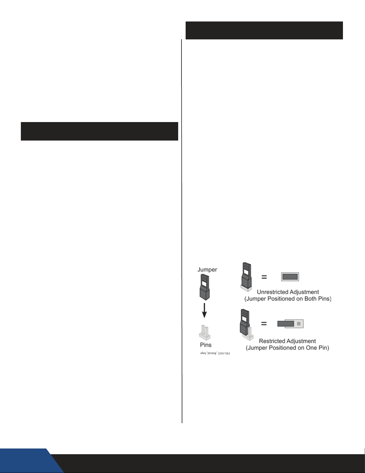
ASd: The Anti-Short Cycle Delay indicates
the time required for the unit to wait before
running again. This parameter is set to 0 min
because Nyle units come equipped with
safety timers already in place.
SF: Sensor Failure indicates that the
temperature sensor has failed.
bLL: Black Light Level indicates the brightness
of the LCD screen.
RESTRICTED MODE
Switching the Controller to Restricted Mode will
prevent users from adjusting most or all of the
parameter settings. The main screen will
function normally.
Note: The OFF parameter is the only parameter
that can be accessed in Restricted Mode. So be
sure that your desired parameter values are set
before changing over to restricted mode.
ADVANCED MODE
In Advanced mode you can adjust all of the basic
parameters as well as; Un, Tsb, So, HtS and LtS.
The main function of this mode is to add more
control over your unit and to set restrictions for
parameters in basic mode.
Advanced Mode Menu:
From the main screen press and hold both arrow
keys simultaneously. The screen will display the
ashing Un parameter to indicate that you have
entered the menu.
Un: Indicates the temperature units. This can be
in either Fahrenheit (°F) or Celsius (°C).
LtS: Low Temp. Stop indicates the lowest
temperature that the On or OFF parameters can
be set to in Basic Mode.
In addition, the differential between the
OFF/ON parameters is fixed in restricted mode.
If the OFF parameter is adjusted the On
parameter will adjust to maintain the differential.
Setting the controller to restricted mode:
• Turn power off from the controller
• Carefully remove the front panel
• Locate the jumper and carefully position it on
one pin as shown in the diagram below.
The controller is now in restricted mode. Securely
replace the cover before reconnecting power to
the controller.
HtS: High Temp. Stop indicates the highest
temperature that the On or OFF parameters can
be set to in Basic Mode.
tSb: Temp Setback indicates the value for
setting back the On and OFF temperature
values. Default to 0°F because it is not
applicable to the application of this unit type.
So: Sensor Offset allows for compensation
of any difference between the displayed
temperature and the temperature being read by
the sensor.
32
Lock out
You can format your parameters to completely
restrict all user adjustment of the control when
in restricted mode. To do this set the HtS value
equal to the OFF value and the LtS equal to the
On value. This makes the OFF/On range equal
to the HtS/LtS range and thereby unadjustable in
restricted mode.
Page 33
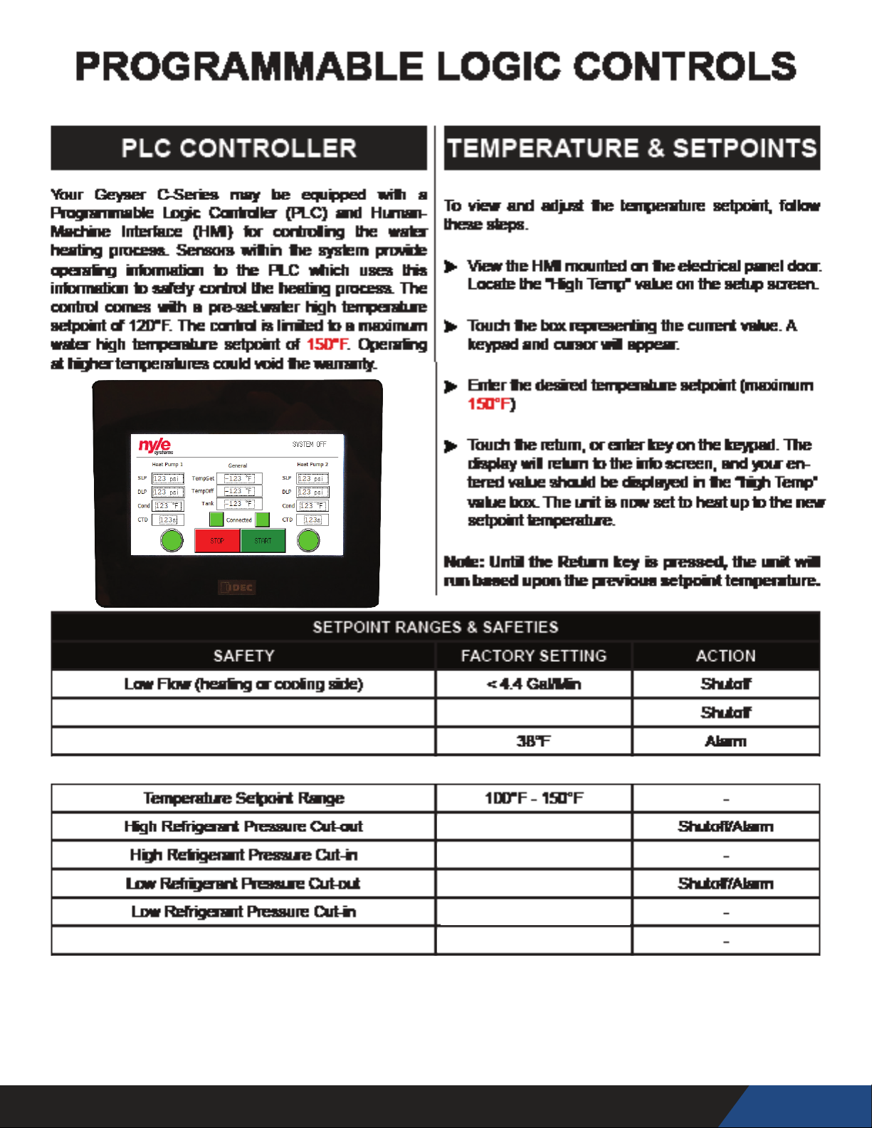
Evaporator temperature defrost cut-in
Evaporator temperature defrost cut-out
Compressor Anti-Short Cycle Delay 500 sec
Compressor Anti-Short Cycle Delay
34°F
410 PSI
300 PSI
12 PSI
15 PSI
33
Page 34
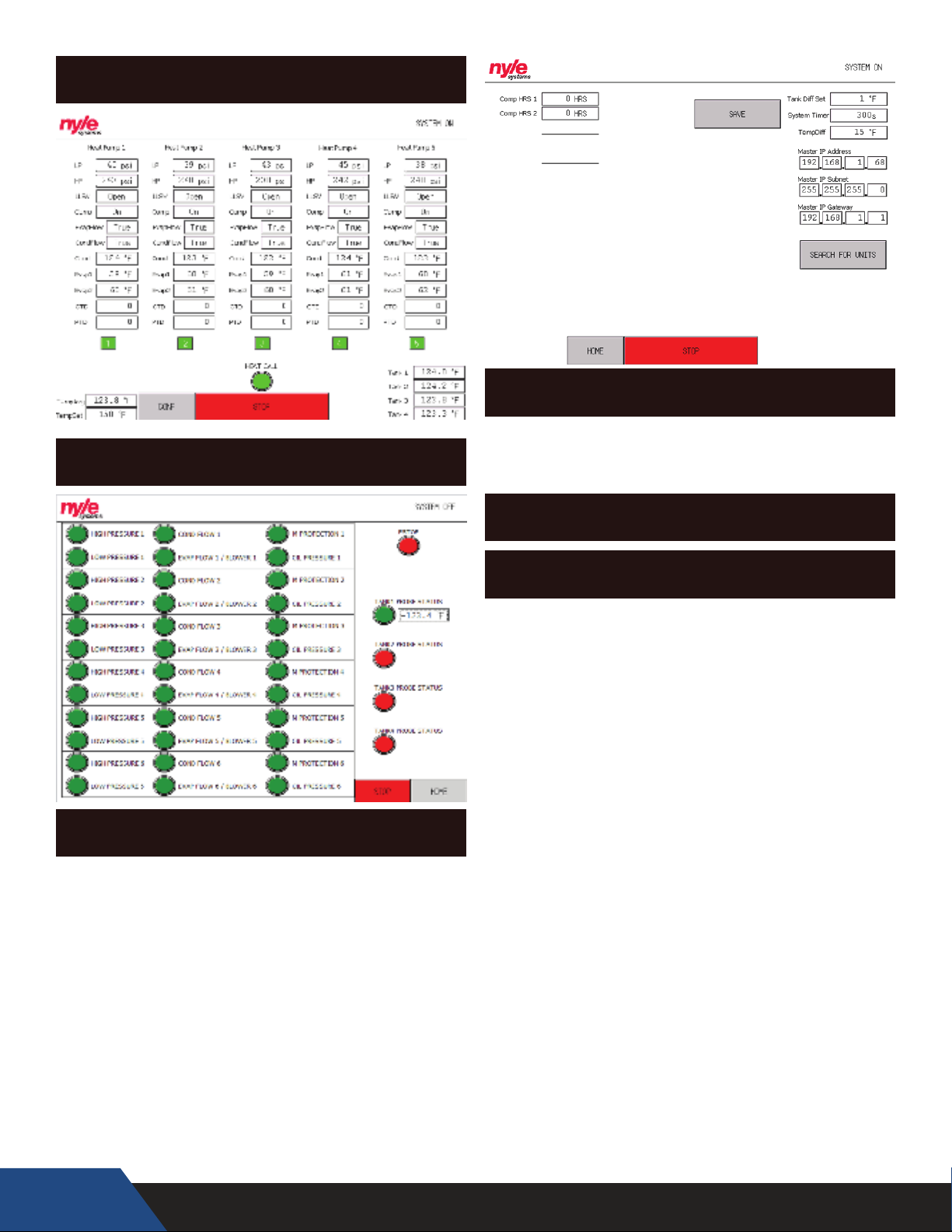
MASTER SCREENS
MASTER PANEL HOME SCREEN
MASTER PANEL CONFIGURATION SCREEN
TERMINOLOGY
MASTER PANEL ALARM SCREEN
HOME SCREEN
“LP” – Low Pressure: indicates the suction line pressure
on the low side of the system
“HP” – High Pressure: indicates the discharge line
pressure on the high side of the system
“LLSV” – Liquid Line Solenoid Valve: indicates the
position of the LLSV (open or closed)
“Comp” – Compressor: indicates the status of the
compressor (on or o)
“EvapFlow” – Evaporator Flow: indicates if the blower
is on (Air to Water HPWH) OR if there is water owing
through the evaporator (Water to Water HPWH)
“CondFlow” – Condenser Flow: indicates if there is
water owing through the condenser
“Cond” – Condenser Temperature: indicates the
leaving water temperature from the condenser
“Evap1” – Evaporator 1: indicates the evaporator
temperature of the rst evaporator
“Evap2” – Evaporator 2: indicates the evaporator
temperature of the second evaporator (only the
C250A Air to Water HPWH has two evaporators)
“CTD” – Compressor Time Delay: indicates remaining
time in compressor delay countdown
“PTD” – Pump Time Delay: indicates remaining time
in pump countdown, when the count down starts the
pump turns on
34
Page 35

Indicator Box – indicates if the unit has been called to
run (green means run, red means on standby)
Heat Call – indicates if the master is calling units to
run to meet building demand (green means run, red
means on standby)
“TempAvg” – Tank Temperature Average: indicates
the average current tank temperature which comes
from all of the valid connected temperature probes
averaged together
“TempSet” – Tank Temperature Setpoint: indicates
the desired tank temperature to be maintained
CONFIGURATION SCREEN
“Comp HRS” – Compressor Hours: indicates the
compressor run time hours of each unit
“Tank Di Set” – Tank Dierential Setpoint: sets the
minimum tank temperature rise required to avoid
calling another unit
“System Timer” – System Timer: sets the maximum
time that the tank has to achieve the Tank Di Set
value to avoid calling another unit
“TempDi” – Temperature Dierence: sets the
dierence below the setpoint where the master will
give a call for slaves to run
“SAVE” button – Saves the “Tank Di Set” and “System
Timer” parameters
“Master IP Address” – IP Address used to connect
panel to BMS system
“Master IP Subnet” – subnet mask for address range
IP is congured in
“Master IP Gateway” – IP Address for internet router
on site used to connect to unit via VPN
ALARM SCREEN
“HIGH PRESSURE 1” – indicates if unit 1 has alarmed
out on high pressure
“LOW PRESSURE 1” – indicates if unit 1 has alarmed
out on low pressure
“COND FLOW 1” – indicates if unit 1 has alarmed out
on condenser water ow
“EVAP FLOW 1 / BLOWER 1” – indicates if unit 1 has
alarmed out on evaporator ow
“M PROTECTION 1” – indicates if unit 1 has alarmed
out on motor protection
“OIL PRESSURE 1” – indicates if unit 1 has alarmed out
on oil pressure
“ESTOP” – indicates if the Estop has been pressed
“TANK1 PROBE STATUS” – indicates if tank 1’s probe is
connected and reading valid data
MASTER CONTROL PANEL
SETUP TO SLAVE UNITS
1) Hardwire all slave units to individual power sources
rated for the equipment with disconnects
2) Hardwire the “Master Control Panel” to a 120V
power supply through the junction box
3) Hardwire each temperature probe into the
junction box for the Master Control Panel and then
permanently attach them to their respective tanks
4) Connect all of the slave units to the router in the
junction box
5) Under the conguration screen press the “SEARCH
FOR UNITS” button to nd all of the connected slaves
(give the master controls 2 minutes to nd all of the
slave units)
6) Check the master screen to make sure that all of the
slave units are connected
MASTER CONTROLS UNIT SUPPORT
CALL SEQUENCE OF OPERATIONS
1) Set the “Tank Di Set” value to 1°F and the “System
Timer” value to 300s (5min), then press save to update
the program
2) Once the master panel determines that there needs
to be a heat call it will determine the unit call order
based on; compressor run hours, alarm status, and
unit number. Then the master will call the unit in the
rst unit in the run order to turn on
3) If the tank temperature does not increase 1°F in 300
seconds than the second unit in the run order will be
called to run
35
Page 36
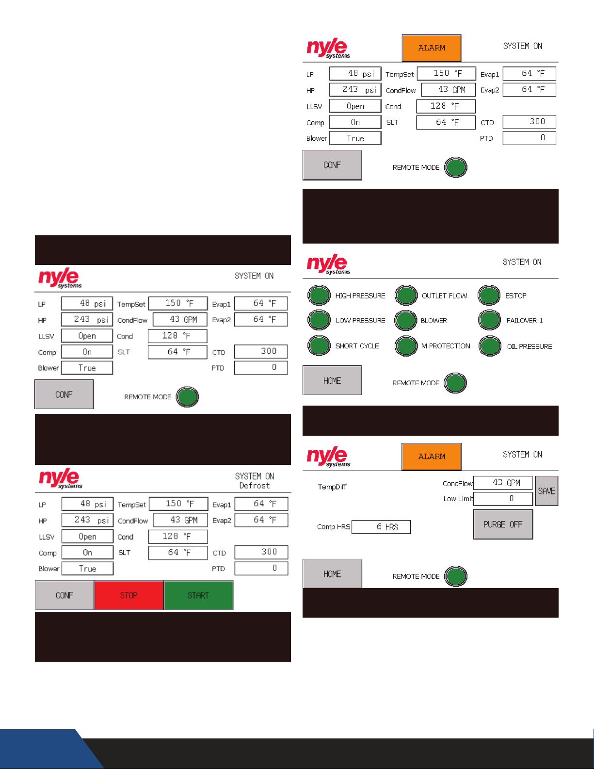
4) The master controls will keep reevaluating these
conditions and calling units as necessary to achieve
the desired rise in the desired amount of time
5) If you nd that the units are not turning on fast
enough to meet building demand change the
“System Timer” to a smaller value in order to have
units turn on quicker
6) If you nd that too many units are turning on and
meeting the building demand very quickly (almost in
a manner of short cycling) you should try increasing
the “Tank Di Set” value so that additional units will
only turn on as needed
SLAVE SCREENS
SINGLE UNIT HOME SCREEN
DISPLAYING ALARM STATUS
SINGLE UNIT HOME SCREEN
OPERATING WITH MASTER CONTROLS
SINGLE UNIT HOME SCREEN
OPERATING AS A SINGLE UNIT (IN DEFROST)
SINGLE UNIT ALARM SCREEN
SINGLE UNIT CONFIGURATION SCREEN
36
Page 37
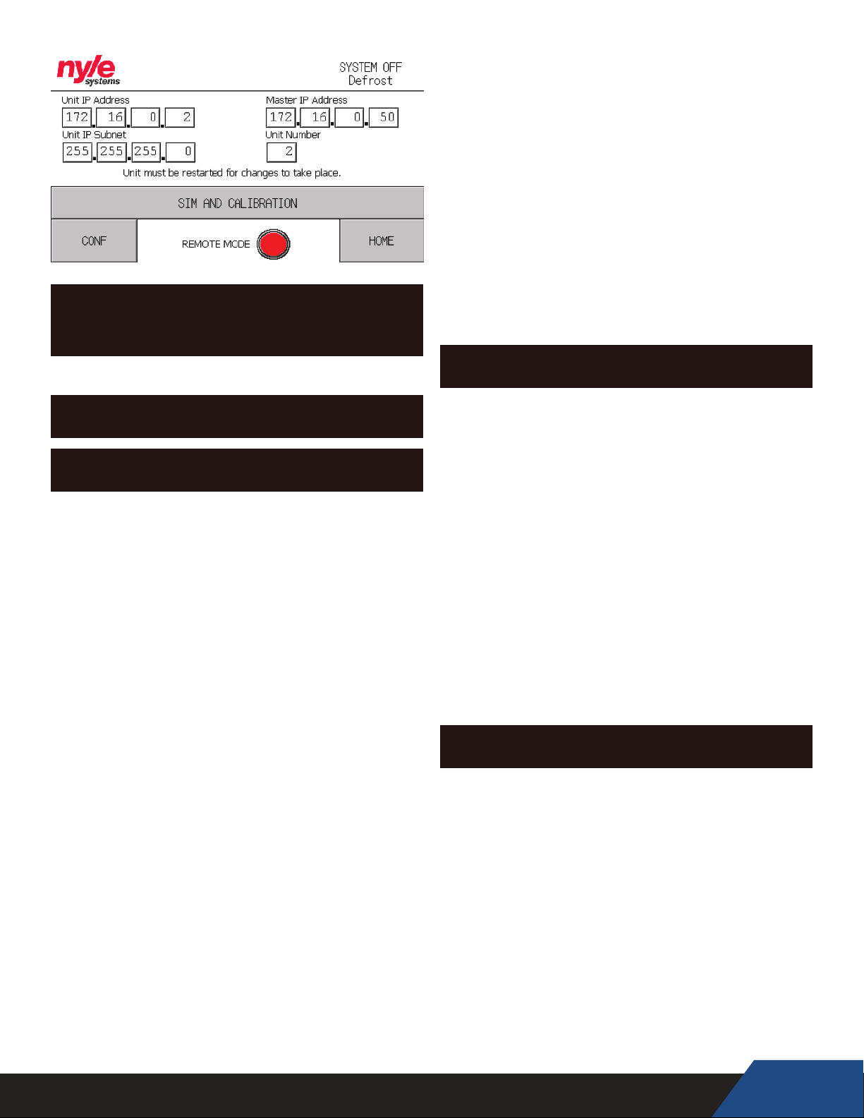
SINGLE UNIT IP ADDRESS CONFIGURATION
SCREEN (FOR USE CONTACT NYLE)
TERMINOLOGY
HOME SCREEN
“LP” – Low Pressure: indicates the suction line pressure
on the low side of the system
“HP” – High Pressure: indicates the discharge line
pressure on the high side of the system
“LLSV” – Liquid Line Solenoid Valve: indicates the
position of the LLSV (open or closed)
“Comp” – Compressor: indicates the status of the
compressor (on or o)
“Blower” – Blower Overload Status: indicates if the
blower motor starter is tripped on an Air to Water
HPWH
“TempSet” – Tank Temperature Setpoint: indicates
the desired tank temperature to be maintained
“CondFlow” – Condenser Flow: indicates if there is
water owing through the condenser
“Cond” – Condenser Temperature: indicates the
leaving water temperature from the condenser
“SLT ” – Suction Line Temperature: indicates the
suction line temperature of the unit right before the
compressor
“Evap1” – Evaporator 1: indicates the evaporator
temperature of the rst evaporator
“Evap2” – Evaporator 2: indicates the evaporator
temperature of the second evaporator (only the
C250A Air to Water HPWH has two evaporators)
“CTD” – Compressor Time Delay: indicates remaining
time in compressor delay countdown
“PTD” – Pump Time Delay: indicates remaining time
in pump countdown, when the count down starts the
pump turns on
Remote Mode Indicator – indicates if this unit is
connected to a master panel via ethernet, if it isn’t
then it will display a start button
Alarm Indicator – indicates if there is a system alarm,
click on the button to see which alarm is currently
triggered
Defrost Indicator – indicates if the unit is in a defrost
cycle (in a defrost cycle the compressor shuts o and
lets the fans run to warm up the evaporator)
CONFIGURATION SCREEN
“TempDi” – Temperature Dierence: sets the
temperature dierence below setpoint where the
unit will turn on (only available if the unit isn’t in
remote mode)
“CondFlow” – Condenser Flow: indicates the owrate
through the condenser (based on frequency read by
PLC through integrated paddle wheel ow sensor)
“Low Limit” – Sets the lowest ow rate limit that
the unit will shut o at (enabled for Single-Pass
applications only), press the save button to save the
lower limit in a Single-Pass conguration
“Comp HRS” – Compressor Hours: indicates the run
hours of the compressor
“Purge” button – this button will run the pump
relay for 2 minutes to allow you to purge the system
without turning on the units
ALARM SCREEN
“HIGH PRESSURE” – indicates if the unit has alarmed
out on high pressure
“LOW PRESSURE” – indicates if the unit has alarmed
out on low pressure
“SHORT CYCLE” – indicates if the unit has been short
cycling
“OUTLET FLOW” – indicates if the unit has alarmed
out on condenser water ow
“BLOWER” – indicates if the blower motor starter as
tripped
“M PROTECTION” – indicates if the unit has alarmed
out on motor protection
37
Page 38
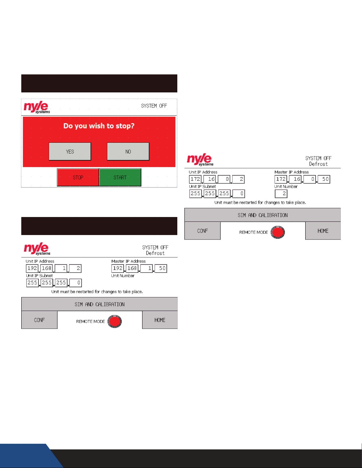
“ESTOP” – indicates if the unit has alarmed out
because an Estop has been pressed
“FAILOVER 1” – indicates if the unit’s temperature
probe has failed
“OIL PRESSURE” – indicates if the unit has alarmed
out on oil pressure
STOP SCREEN
Unit IP Address – This IP address is the designation for
the unit itself, Nyle recommends running the system
on factory settings (ex. 192.168.1.(“Unit Number” AKA
1))
Unit IP Subnet – This number is used to determine
the size of the network the unit is connecting to. (ex.
255.255.255.0)
Master IP Address – This is the address of the Nyle
Systems Master Panel (ex. 192.168.1.50)
Unit Number – Only used for custom network
congurations, this congures your Nyle unit to
connect to a Master Panel under a desired number.
The stop screen will pop up as a conrmation
whenever the “STOP” button on any screen is pressed.
IP CONFIGURATION
New Nyle units can be congured for a variety of
dierent networks on the y and the procedure is
quick and easy to accomplish.
1. Connect the Sim/Conguration Jumper to your
Nyle Systems C250 Unit you would like to congure.
2. Navigate to the “Diag” button in the bottom right
corner of your screen and select “IP Conguration”
38
Page 39
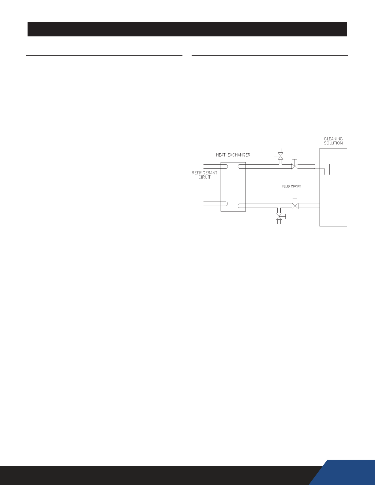
MAINTENANCE AND SERVICE
CLEANING INTERNAL INSULATION
Inspect the internal insulation on a yearly basis for any microbial
growth. The insulation never has to be cleaned unless microbial
growth is detected. If microbial growth is detected, follow the
removal steps below:
1. Disconnect all power to the unit and follow the prescribed
lock-out/tag-out procedure.
2. Wear the prescribed personal protective equipment
prescribed from the cleaning product instructions.
3. Remove as much dirt and organic material from the insulation
using a vacuum device with a HEPA lter (99.97% efcient
at 0.3 micron particles). Be careful not to tear the insulation
during the cleaning procedure.
4. Apply the microbial cleaning agent as prescribed by the
application and usage instructions.
5. Allow the unit to dry thoroughly.
6. If necessary, apply an anti-microbial agent on the insulation
per the instructions provided on the product label.
7. Discard collected microbial contaminants as required by
local or state codes.
BRAZE PLATE CLEANING INSTRUCTIONS
In some applications the heat exchanger may be subjected to
severe uid conditions, including high temperture hard water
conditions, causing accelerated scaling and corrosion rates, and
will diminish performance.
It is important to establish regular cleaning schedules, A 5%
solution of Phosphoric Acid or Oxalic Acid may be considered.
Other types of solutions can be obtained from your local
wholesaler. Make sure cleaning solution is applicable for stainless
steel and copper and all directions are followed.
Do not heat solution. Be sure to flush heat exchanger with
fresh water after cleaning. See Figure 12.
Figure 12
39
Page 40
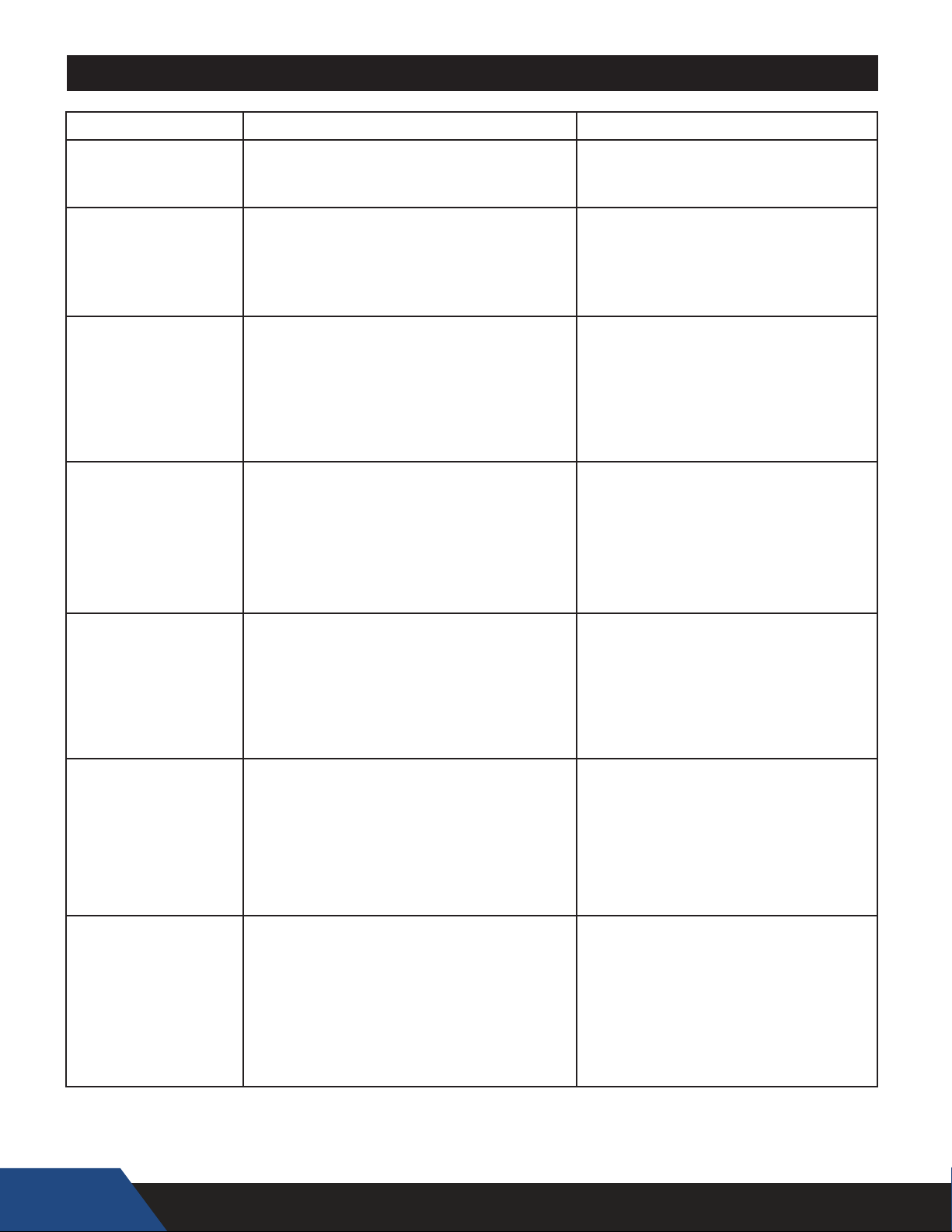
TROUBLESHOOTING
CHECKING REFRIGERANT CHARGE
Servicing of the refrigeration circuit must only be performed
by agencies or individuals possessing Type II or Universal
certification as defined in Section 608 of the Clean Air Act. See
Qualifications on page 8.
This HPWH unit is factory charged with 134a refrigerant. See the
rating label on the HPWH unit and Table 9 for refrigerant charge
by weight. It should not be necessary to add or remove refrigerant
during installation or start up. Refrigerant lost during frequent
refrigerant pressure testing can cause low refrigerant conditions.
Air and water ow should always be checked rst to eliminate
other potential problems before checking the refrigerant charge.
Check Water Temperature Rise
Always check water temperature rise through the HPWH
unit’s internal heat exchanger before checking the refrigerant
charge. See Start Up on page 29 for information on how to
measure the water temperature rise.
If the measured water temperature rise during start up was
within 8°F to 12°F (4°C to 7°C) checking the charge is not
necessary unless other conditions warrant testing.
If the measured temperature rise through the HPWH unit is less
than 8°F (4°C) checking the charge is not necessary unless
other conditions warrant testing. Short water piping runs
between the HPWH and the storage tank will produce lower
temperature rises and are not problematic.
If the measured temperature rise through the HPWH unit is
more than 12°F (7°C) check for restrictions in the inlet and
outlet water piping connected between the HPWH unit and the
storage tank.
SUPERHEAT CALCULATION
1.
2.
Measure and record the suction pressure at the
suction line pressure access port inside the unit.
Convert the recorded suction pressure to
saturated temperature.
3. Measure the suction line temperature near the suction line
pressure access port inside the unit.
4. Compare the suction line temperature to the to the saturated
temperature in Table 10.
TABLE 10
R134A SATURATED TEMPERATURE CHART
SATURATED
TEMPERATURE °F
SATURATED
TEMPERATURE °C
REFRIGERANT
PRESSURE (PSI)
0 -18 7
5 -15 9
10 -12 12
15 -9 15
20 -7 18
25 -4 22
30 -1 26
35 2 30
40 4 35
45 7 40
50 10 45
55 13 51
60 16 57
65 18 64
70 21 71
75 24 79
80 27 87
85 29 95
90 32 104
95 35 114
100 38 124
105 41 135
110 43 146
115 46 158
120 49 171
125 52 185
130 54 199
135 57 214
140 60 229
145 63 246
150 66 263
155 68 281
5. The difference between saturated temperature and suction
line temperature is the superheat. Superheat normal range
should be 8°F to 12°F (4.4°C to 6.7°C).
TABLE 9
MODEL FACTORY CHARGE R134A
C25
7#
C60
C90
C125
C185
C250
14#
20#
60#
PROBLEM POSSIBLE CAUSES CORRECTIONS
Heat pump is too noisy.
Water on oor around
the heat pump and/or
water tank.
Heat pump is not running -
electrical issues.
Heat pump is not running -
high pressure fault
Heat pump is not running -
low pressure fault
Water is never hot enough.
* Reset the heat pump by removing then restoring power to the unit at the breaker or from the manual switch. (There will be a three minute delay
before heat pump restarts.) If the heat pump cuts out again on LOW or HIGH PRESSURE, additional troubleshooting is necessary to nd the cause
DO NOT CONTINUE TO RESET THE HEAT PUMP, AS CONTINUED SHORT-CYCLING MAY STRESS OR DAMAGE INTERNAL COMPONENTS.
40
1. Sheet metal fasteners are loose.
2. Operating vibration is transferring to oor or
building structure.
1. Tubing, valves, or fittings are leaking.
4. Condensation forming on the bottom of unit
1. Circuit does not have adequate ampacity.
2. Short circuit or loose connection in field wiring.
3. Short circuit or loose connection in the cabinet
4. Thermostat failure.
5. Defective anti-short cycle timer.
6. Compressor burn-out.
1. Thermostat setting too high
2. Source Water temperature over 100° F
3. Low water flow causes
A. external pump is not operating
B. piping between the heat pump and storage tank
exceeds 50 equivalent feet
C. heat exchanger has scale buildup
D. shut off valves are partially closed
1. Source Water temperature below 40°F
2. Loss of refrigerant
1. Thermostat setting is too low.
2. Heat pump/storage tank undersized for application.
3.
Heat pump is not properly connected to storage tank.
4. Unit cooling coil is overcooling the source water.
Tighten fasteners.
Place vibration dampeners underneath unit.
Repair leaks as necessary.
Shim unit to level. See installation section.
Cover bottom of unit with foam insulation.
Refer to nameplate for unit requirements.
Check eld wiring diagram. Tighten all connections.
Check for loose wiring and tighten.
Replace thermostat
Reset phase monitor
Unknown
Replace compressor (refer to compressor change-out
page)
Thermostat setting should not exceed 150°F.
Keep heat pump off until room temperature
is back in operating range
Low water ow corrections
replace unit pump
reduce piping or add booster pump
clean heat exchanger with a mild acid wash
open all shut off valves
Keep heat pump off until room temperature is back in
operating range
Find source of leak, repair and recharge
Set thermostat for storage tank to a higher temperature.
Increase size of storage tank or install gas or electric heater
to make up for shortfall.
Refer to field piping diagrams for recommended piping.
Page 41
CHECKING REFRIGERANT CHARGE
Servicing of the refrigeration circuit must only be performed
by agencies or individuals possessing Type II or Universal
certification as defined in Section 608 of the Clean Air Act. See
Qualifications on page 8.
This HPWH unit is factory charged with 134a refrigerant. See the
rating label on the HPWH unit and Table 9 for refrigerant charge
by weight. It should not be necessary to add or remove refrigerant
during installation or start up. Refrigerant lost during frequent
refrigerant pressure testing can cause low refrigerant conditions.
Air and water ow should always be checked rst to eliminate
other potential problems before checking the refrigerant charge.
Check Water Temperature Rise
Always check water temperature rise through the HPWH
unit’s internal heat exchanger before checking the refrigerant
charge. See Start Up on page 29 for information on how to
measure the water temperature rise.
If the measured water temperature rise during start up was
within 8°F to 12°F (4°C to 7°C) checking the charge is not
necessary unless other conditions warrant testing.
If the measured temperature rise through the HPWH unit is less
than 8°F (4°C) checking the charge is not necessary unless
other conditions warrant testing. Short water piping runs
between the HPWH and the storage tank will produce lower
temperature rises and are not problematic.
If the measured temperature rise through the HPWH unit is
more than 12°F (7°C) check for restrictions in the inlet and
outlet water piping connected between the HPWH unit and the
storage tank.
SUPERHEAT CALCULATION
Measure and record the suction pressure at the
1.
suction line pressure access port inside the unit.
Convert the recorded suction pressure to
2.
saturated temperature.
3. Measure the suction line temperature near the suction line
pressure access port inside the unit.
4. Compare the suction line temperature to the to the saturated
temperature in Table 10.
5. The difference between saturated temperature and suction
line temperature is the superheat. Superheat normal range
should be 8°F to 12°F (4.4°C to 6.7°C).
TABLE 9
MODEL FACTORY CHARGE R134A
C25
C60
C90
C125
C185
C250
7#
14#
20#
60#
TABLE 10
R134A SATURATED TEMPERATURE CHART
SATURATED
TEMPERATURE °F
0 -18 7
5 -15 9
10 -12 12
15 -9 15
20 -7 18
25 -4 22
30 -1 26
35 2 30
40 4 35
45 7 40
50 10 45
55 13 51
60 16 57
65 18 64
70 21 71
75 24 79
80 27 87
85 29 95
90 32 104
95 35 114
100 38 124
105 41 135
110 43 146
115 46 158
120 49 171
125 52 185
130 54 199
135 57 214
140 60 229
145 63 246
150 66 263
155 68 281
SATURATED
TEMPERATURE °C
REFRIGERANT
PRESSURE (PSI)
41
Page 42
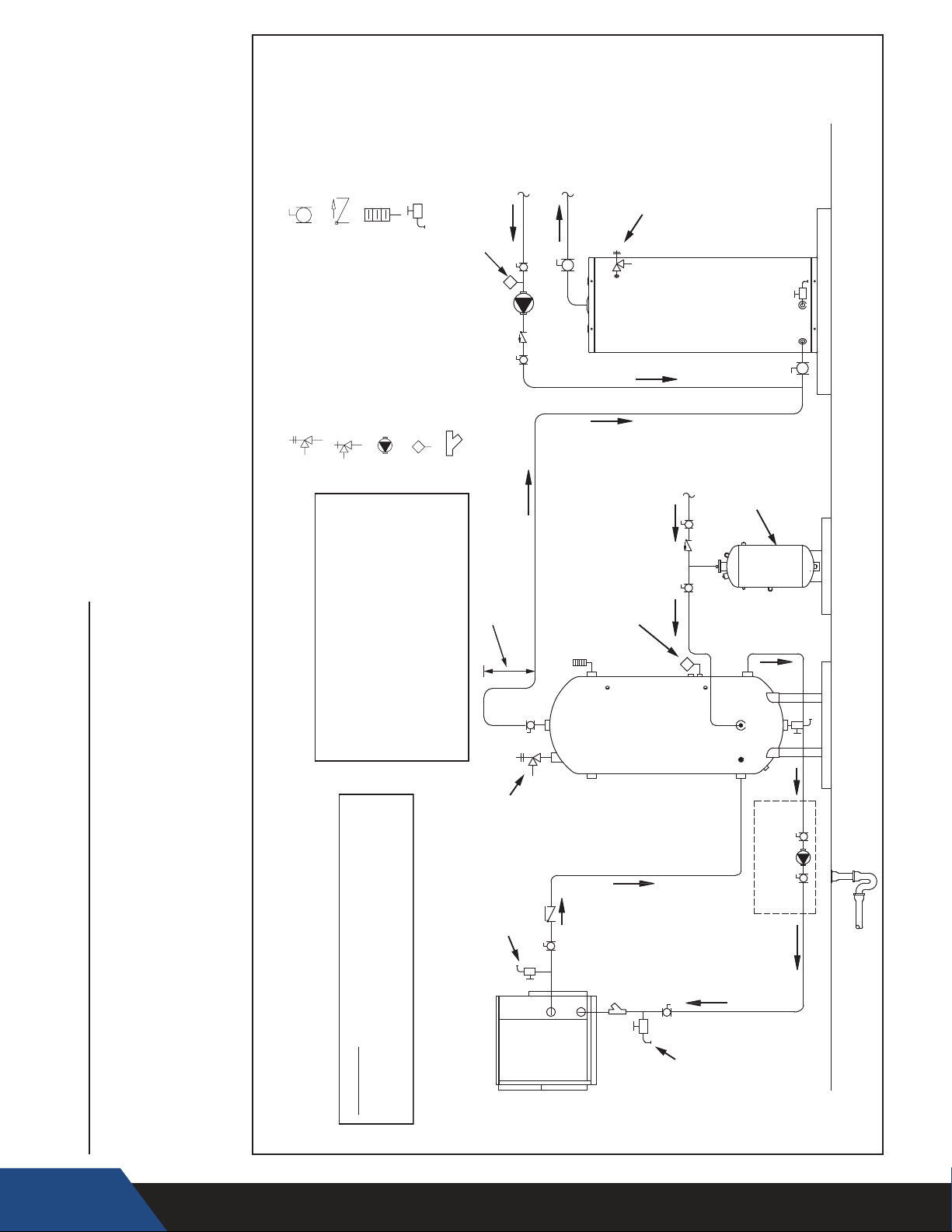
LEGEND
thermostat.
4. See Closed Systems and Thermal Expansion on page 13
5. See Water Connections on page 17.
6. If a building recirculation loop is present the circulation pump must be controlled by a
BUILDING
RECIRCULATION
LOOP RETURN
HOT WATER
OUT TO
FULL PORT BALL VALVE
CHECK VALVE
TEMPERATURE & PRESSURE
PRESSURE RELIEF VALVE
RELIEF VALVE
DRAIN
TEMPERATURE GAGE
TANK OR LINE TEMPERATURE
CIRCULATING PUMP
WYE STRAINER
CONTROL
LINE THERMOSTAT
WATER OUT
PREHEATED
HEAT TRAP PIPING
MINIMUM 18 INCHES
FIXTURES
PIPE T&P TO
BACKUP
TAN K
THERMOSTAT
OPEN DRAIN
WATER
HEATER
COLD
WATER
SUPPLY
EXPANSION
TANK
TO THE STORAGE TANK ON PREHEAT
IMPORTANT INSTALLATION NOTES:
1. COLD WATER SUPPLY MUST CONNECT
PIPING CONFIGURATION AND OTHER DEVICES;
ONE HEAT PUMP, SINGLE TEMPERATURE, PREHEAT SYSTEM WITH
VERTICAL STORAGE TANK AND BACKUP WATER HEATER
3. See Temperature - Pressure Relief Valve on page 14.
WATER PIPING DIAGRAMS
2. See Water Temperature on page 10.
Before installation of water piping review the following:
1. See Mixing Valves on page 13.
WARNING: THIS DRAWING SHOWS SUGGESTED
WITH FORCED BUILDING RECIRCULATION
SYSTEMS
RETURN LINE MUST CONNECT TO THE
INLET OF THE BACKUP WATER HEATER
ON PREHEAT SYSTEMS.
2. BUILDING RECIRCULATION LOOP
PURGE &
CHECK WITH LOCAL CODES AND ORDINANCES
FOR ADDITIONAL REQUIREMENTS.
PIPE T&P TO
OPEN DRAIN
VALV E
FLUSH
HPWH
STORAGE
WATER
(OUTLET)
SUPPLY
TANK
RETURN
WATER
(INLET)
VALV E
FLUSH
DRAIN &
SUPPLY
FOR HPWH MODELS
FIELD SUPPLIED PUMP
WITHOUT FACTORY PUMP
FINISHED
FLOOR
42
Page 43
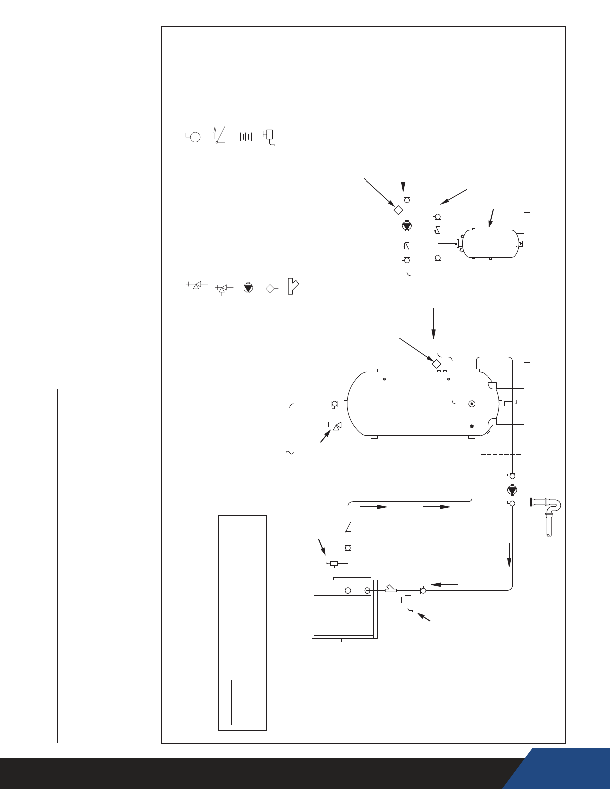
FULL PORT BALL VALVE
CHECK VALVE
DRAIN
TEMPERATURE GAGE
LEGEND
thermostat.
4. See Closed Systems and Thermal Expansion on page 13
5. See Water Connections on page 17.
6. If a building recirculation loop is present the circulation pump must be controlled by a
NOTE:
CONNECT BUILDING
RECIRC RETURN TO
INLET OF BACKUP
WATER HEATER
WHEN PRESENT
COLD WATER
SUPPLY
EXPANSION
TANK
BUILDING
RECIRCULATION
LOOP RETURN
LINE THERMOSTAT
WYE STRAINER
TANK OR LINE TEMPERATURE
TEMPERATURE & PRESSURE
RELIEF VALVE
PRESSURE RELIEF VALVE
CONTROL
CIRCULATING PUMP
TANK THERMOSTAT
TANK
STORAGE
PIPING CONFIGURATION AND OTHER DEVICES;
ONE HEAT PUMP, SINGLE TEMPERATURE WITH
VERTICAL STORAGE TANK
3. See Temperature - Pressure Relief Valve on page 14.
WATER PIPING DIAGRAMS
2. See Water Temperature on page 10.
Before installation of water piping review the following:
1. See Mixing Valves on page 13.
WARNING: THIS DRAWING SHOWS SUGGESTED
WITH FORCED BUILDING RECIRCULATION
HOT OUTLET
WATER HEATER
TO FIXTURES OR
INLET OF BACKUP
PIPE T&P TO
OPEN DRAIN
FLUSH
PURGE &
CHECK WITH LOCAL CODES AND ORDINANCES
FOR ADDITIONAL REQUIREMENTS.
VALV E
SUPPLY
HPWH
WATER
(OUTLET)
(INLET)
WATER
RETURN
VALV E
FLUSH
DRAIN &
SUPPLY
FOR HPWH MODELS
FIELD SUPPLIED PUMP
WITHOUT FACTORY PUMP
FINISHED
FLOOR
43
Page 44
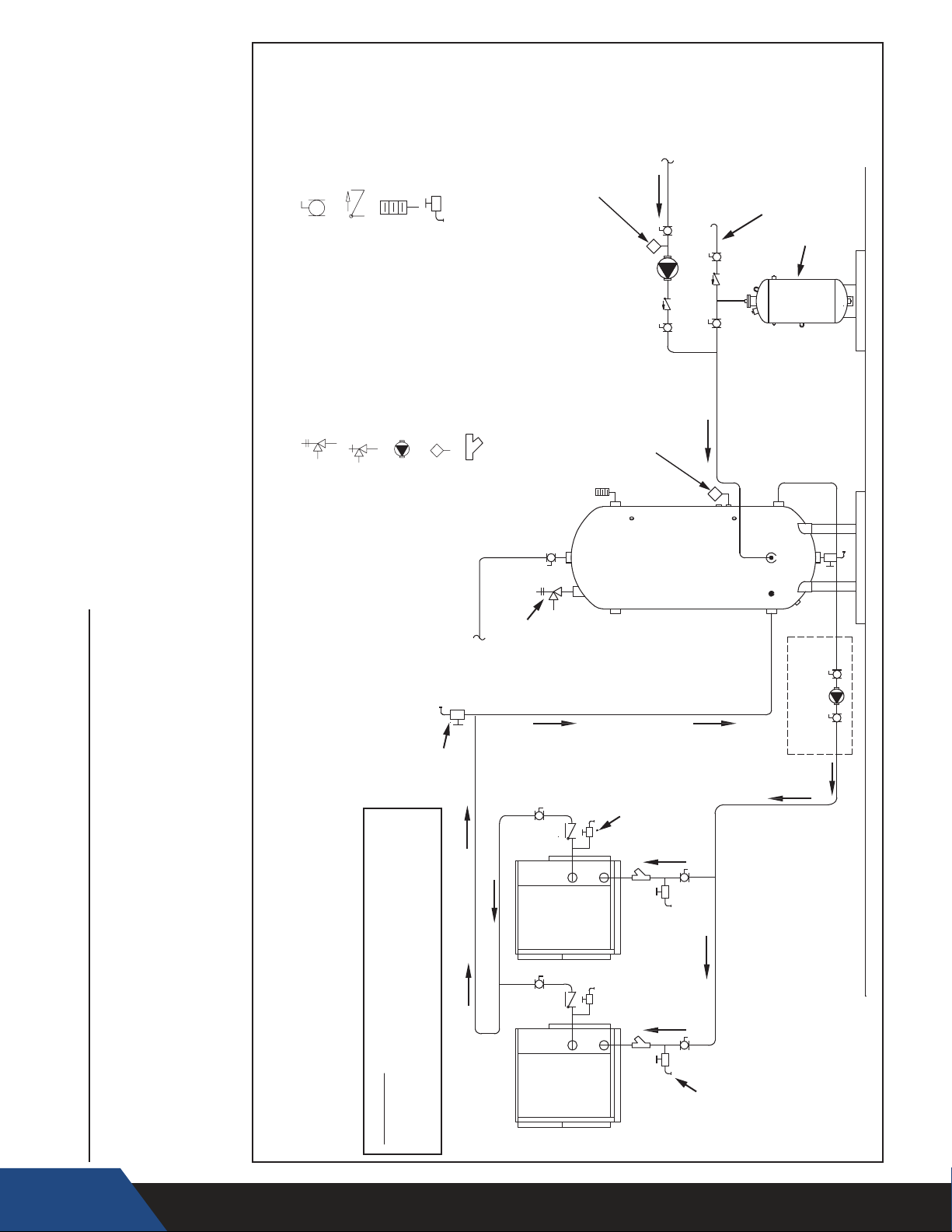
NOTE:
CONNECT BUILDING
BUILDING
RECIRC RETURN TO
RECIRCULATION
LOOP RETURN
WHEN PRESENT
INLET OF BACKUP
WATER HEATER
LEGEND
thermostat.
4. See Closed Systems and Thermal Expansion on page 13
5. See Water Connections on page 17.
6. If a building recirculation loop is present the circulation pump must be controlled by a
FULL PORT BALL VALVE
TEMPERATURE & PRESSURE
RELIEF VALVE
CHECK VALVE
PRESSURE RELIEF VALVE
TEMPERATURE GAGE
CIRCULATING PUMP
DRAIN
WYE STRAINER
TANK OR LINE TEMPERATURE
CONTROL
HOT OUTLET
WATER HEATER
TO FIXTURES OR
INLET OF BACKUP
LINE THERMOSTAT
TANK THERMOSTAT
TANK
STORAGE
COLD WATER
SUPPLY
EXPANSION
TANK
TWO HEAT PUMPS, SINGLE TEMPERATURE WITH
VERTICAL STORAGE TANK
3. See Temperature - Pressure Relief Valve on page 14.
WATER PIPING DIAGRAMS
2. See Water Temperature on page 10.
Before installation of water piping review the following:
1. See Mixing Valves on page 13.
WITH FORCED BUILDING RECIRCULATION
PIPE T&P TO
OPEN DRAIN
VALV E
PURGE
WATER
(OUTLET)
SUPPLY
PIPING CONFIGURATION AND OTHER DEVICES;
WARNING: THIS DRAWING SHOWS SUGGESTED
CHECK WITH LOCAL CODES AND ORDINANCES
FOR ADDITIONAL REQUIREMENTS.
HPWHHPWH
FLUSH
VALV ES
FLUSH
VALV ES
DRAIN &
(INLET)
WATER
RETURN
SUPPLY
FOR HPWH MODELS
FIELD SUPPLIED PUMP
WITHOUT FACTORY PUMP
FINISHED
FLOOR
44
Page 45
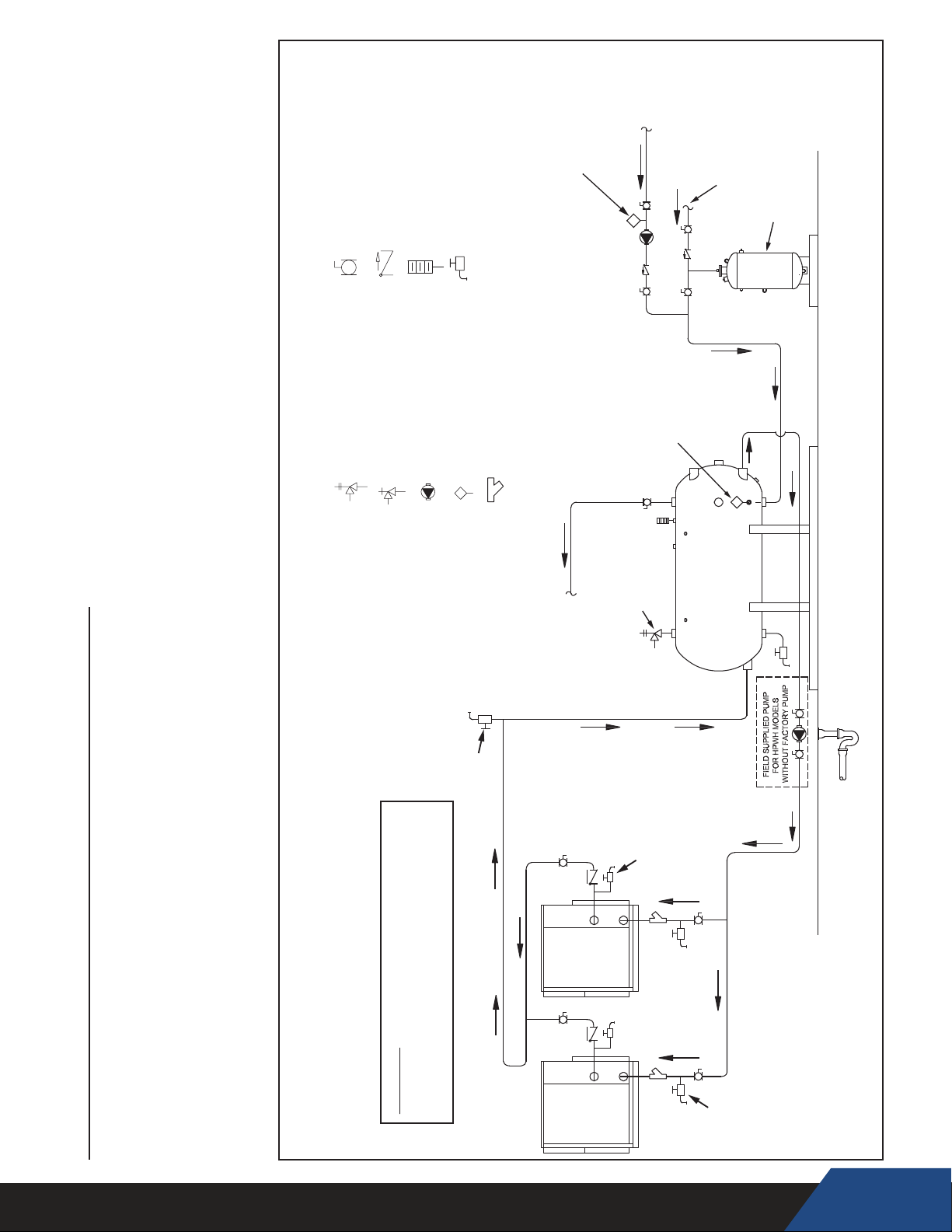
CHECK VALVE
FULL PORT BALL VALVE
LEGEND
TEMPERATURE & PRESSURE
RELIEF VALVE
PRESSURE RELIEF VALVE
DRAIN
TEMPERATURE GAGE
TANK OR LINE TEMPERATURE
CIRCULATING PUMP
WYE STRAINER
CONTROL
BUILDING
RECIRCULATION
LOOP RETURN
LINE THERMOSTAT
NOTE:
CONNECT BUILDING
TANK THERMOSTAT
RECIRC RETURN TO
INLET OF BACKUP
WATER HEATER
WHEN PRESENT
COLD WATER
SUPPLY
EXPANSION
TANK
thermostat.
4. See Closed Systems and Thermal Expansion on page 13
5. See Water Connections on page 17.
6. If a building recirculation loop is present the circulation pump must be controlled by a
VALV E
PURGE
HOT OUTLET
WATER HEATER
TO FIXTURES OR
INLET OF BACKUP
WATER
(OUTLET)
SUPPLY
HPWHHPWH
PIPE T&P TO
OPEN DRAIN
FLUSH
VALVES
TANK
STORAGE
SUPPLY
RETURN
WATER
(INLET)
FINISHED
FLOOR
TWO HEAT PUMPS, SINGLE TEMPERATURE WITH
HORIZONTAL STORAGE TANK
WITH FORCED BUILDING RECIRCULATION
3. See Temperature - Pressure Relief Valve on page 14.
WATER PIPING DIAGRAMS
2. See Water Temperature on page 10.
Before installation of water piping review the following:
1. See Mixing Valves on page 13.
WARNING: THIS DRAWING SHOWS SUGGESTED
PIPING CONFIGURATION AND OTHER DEVICES;
CHECK WITH LOCAL CODES AND ORDINANCES
FOR ADDITIONAL REQUIREMENTS.
FLUSH
VALVES
DRAIN &
45
Page 46

LIMITED WARRANTY
COMMERCIAL HEAT PUMP WATER HEATERS
Nyle Systems, the warrantor, extends the following LIMITED WARRANTY to the original owner of this commercial heat pump water heater
subject to the terms, conditions and disclaimers stated below:
1. COMPRESSOR
If the 5-Year Extended Compressor Warranty is purchased, and if within FIVE (5) years after delivery of this heat pump water heater the
compressor shall prove, upon examination by the warrantor, to be defective, the warrantor will provide a replacement compressor.
2. ALL OTHER PARTS
If within ONE (1) year after delivery of this heat pump water heater any other part or portion shall prove, upon examination by the warrantor,
to be defective in material or workmanship, the warrantor will repair or replace such part or portion at its option. This warranty also extends
to any factory supplied accessories.
3. CONDITIONS AND EXCEPTIONS
Refrigerant, filters, refrigerant driers, and fan belts are not covered under this limited warranty. The warranty on all replacement parts, including
the compressor, will be limited to the unexpired term of the original warranty. This warranty shall apply only when the heat pump water heater is
installed in accordance with local plumbing and building codes, ordinances and regulations, the warranter's printed instructions provided with it
and good industry practices.
a. This warranty shall apply only when the unit is:
(1) used at temperatures not exceeding the maximum system temperatures printed in the instructions provided;
(2) filled with potable water, free to circulate at all times and free of damaging water sediment or scale deposits;
(3) used in a non-corrosive and not contaminated atmosphere;
(4) in its original installation location, and under original ownership;
(5) in the United States, its territories or possessions, Canada, South America, Caribbean and Mexico;
(6) sized in accordance with proper sizing techniques for commercial heat pump water heaters;
(7) bearing the original rating label which has not been altered, defaced or removed, except as required by the warranter;
(8) energized at the proper voltage and phase as stated on the rating label;
(9) maintained in accordance with the instructions printed in the manual included with the heat pump water heater;
b. Any accident to the water heater, any misuse, abuse (including freezing) or alteration of it, any operation of it in a modified form, will
void this warranty.
4. SERVICE REPAIR AND EXPENSE
Under this limited warranty the warranter will provide only a replacement heat pump water heater or part thereof. The owner is responsible for all
other costs. Such costs may include but are not limited to:
a. Labor charges for service, removal, repair, or re installation of the water heater or any component part;
b. Shipping, delivery, handling, and administrative charges for forwarding the new heater or replacement part from the nearest
distributor and returning the claimed defective heater or part to such distributor;
c. All cost necessary or incidental for any materials and/or permits required for installation of the replacement heater or part.
5. LIMITATIONS ON IMPLIED WARRANTIES
Implied warranties, including any warranty of merchantability imposed on the sale of this heater under state law are limited to one (1) year duration for the heater or any of its parts. Some states do not allow limitations on how long an implied warranty lasts, so the above limitation may not
apply to you.
6. CLAIM PROCEDURE
Any claim under this warranty should be initiated with the dealer who sold the heater, or with any other dealer handling the
warrantor’s products. If this is not practicable, the owner should contact:
Nyle Systems, LLC
12 Stevens Road
Brewer, Maine 04412
Telephone: 1-800-777-6953
a. The warrantor will only honor replacement with identical or similar water heater or parts thereof which are
manufactured or distributed by the warrantor.
b.
Dealer replacements are made subject to in-warranty validation and approval by warrantor.
7. DISCLAIMERS
NO OTHER EXPRESS WARRANTY HAS BEEN OR WILL BE MADE IN BEHALF OF THE WARRANTOR WITH RESPECT TO THE MERCHANTABILITY
OF THE HEATER OR THE INSTALLATION, OPERATION, REPAIR, OR REPLACEMENT OF THE HEATER. THE WARRANTOR SHALL NOT BE
RESPONSIBLE FOR WATER DAMAGE, LOSS OF USE OF THE UNIT, INCONVENIENCE, LOSS OR DAMAGE TO PERSONAL PROPERTY, OR
OTHER CONSEQUENTIAL DAMAGE. THE WARRANTOR SHALL NOT BE LIABLE BY VIRTUE OF THIS WARRANTY OR OTHERWISE FOR
DAMAGE TO ANY PERSONS OR PROPERTY, WHETHER DIRECT OR INDIRECT, AND WHETHER ARISING IN CONTRACT OR IN TORT.
a. Some states do not allow the exclusion or limitation of the incidental or consequential damage, so the above limitation or
exclusion may not apply to you.
b. This warranty gives you specic legal rights, and you may also have other rights which vary from state to state.
46
Page 47

Fill in the following for your own reference. Keep it. Registration is not a condition of warranty. The model and serial number are found
on the heater’s rating label.
Model No. Serial No. Date Installed
Dealer’s Name
Dealer’s Address Phone No.
City and State Zip
Nyle Systems, LLC
12 Stevens Road
Brewer, Maine 04412
1-800-777-6953
Sales: Ext 216
Service : Ext 208
47
 Loading...