

Page 1
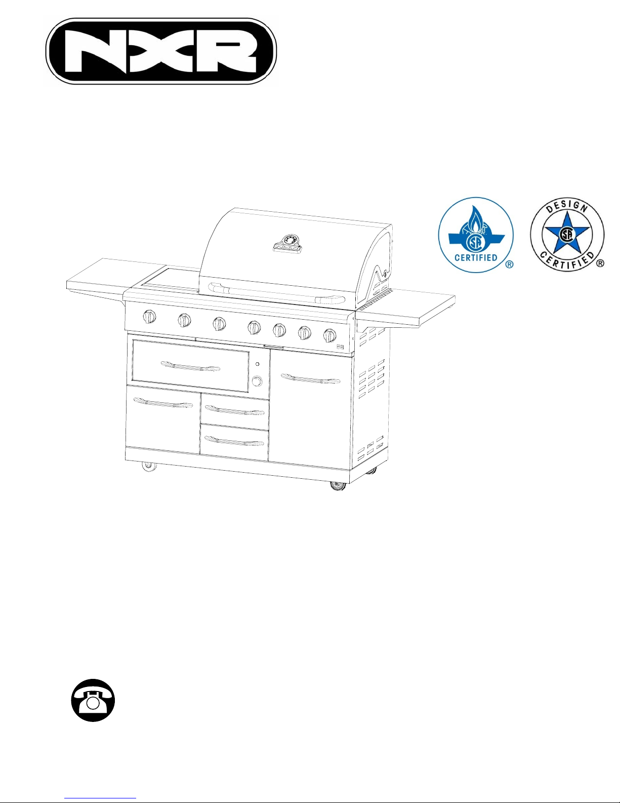
ITM./ART. 965490
Model: 780-0832C
0
Gas Grill Manual for Installation, Care & Maintenance
IMPORTANT, RETAIN FOR FUTURE REFERENCE: READ CAREFULLY
Warning:
For outdoor use only.
This instruction manual contains important information necessary for the proper
assembly and safe use of the appliance.
Do not leave the appliance unattended. Keep young children and pets away.
Do not move the device during use.
Not intended to be installed in or on boats and should never be used as a heater.
Close the valve of the gas cylinder after use.
Questions, problems, missing parts? Before returning to your retailer, call our customer
service department at 1-877-639-7264, 9 a.m.-5 p.m., PST, Monday-Friday. English,
French, and Spanish representatives are available. Send email to: nxrcs@duro-global.com
Page 2
Thank you for purchasing your NXR outdoor grill.
We appreciate your business and we recommend that you read this entire User’s Manual
before operating your new appliance for the first time.
This manual contains instructions on how to properly install and set up your new grill, as well
as insights into the unique features that our product offers. Please keep this manual for future
reference, as it contains answers to questions that you might have as you begin to cook.
Thank you,
Duro Corporation Inc.
CALIFORNIA PROPOSITION 65 WARNING
WARNING: This product contains chemicals
known to the State of California to cause cancer
and birth defects or other reproductive harm.
2
Page 3

Table of Contents
SafetyInstruction............... ............4-11
ExplodedView............. ....................12
PartList......................................13-14
AssemblyInstruction.........................15-17
LPGasHook-up............ ................18-19
LPLeakTesting..................................20
NGGasConversion.................. ........21-26
MatchLightingInstruction......................32
LightInstruction................. ..........33-34
MotorInstruction............. ...............35
CareandMaintenance.............. ..........36
UninstallDrawer............. .................37
IceBucket...... ........... .................37
GreaseTray....................................38
NGGasHook-up................................27
NGLeakTesting..................................28
OperatingInstruction............................29
GrillLightingInstruction.....................30-31
Cookingtips......................... .........39
TroubleShooting............................40-41
Ordering Parts ........................42
Limited Warranty
....................43-44
3
Page 4
Safety Instruction
If the information in this manual is not followed exactly, a fire or an explosion may result causing
property damage, personal injury or even death.
Do not store or use gasoline, liquid propane cylinder or other flammable vapors and liquids in the
vicinity of this appliance.
What to do if you smell gas?
Donottrytolightanyappliance.
Do not touch any electrical switch.
Do not use any phone in your residence.
Immediately call your gas supplier from a neighbor’s phone. Follow the gas supplier’s instructions.
If you cannot reach your gas supplier, call the fire department.
For installation and service of your grill product, it must be performed by a licensed installer, an
approved service agency or your gas supplier.
Gas appliances can cause minor exposure to four of these substances, namelybenzene,carbon
monoxide, formaldehyde and soot, caused primarily by the incomplete combustion of natural gas
fuel. When operating your grill on liquid propane, the flames from the burners should be blue in
color. In addition, the flames should be stable, free of yellow tipping, excessive noise and lifting.
However, this yellow tipping should be restricted to the primary flame kernels only. Properly adjusted
burners, indicated by a bluish rather than a yellow flame, will minimize incomplete combustion.
Exposure to those substances can be minimized by venting with an open window or use of a
ventilation fan or hood.
4
Page 5
y
Safety Instruction
WARNING
Do not try lighting this appliance without reading the
“LIGHTING INSTRUCTIONS” section ofthis manual.
TESTED IN ACCORDANCE WITH ANS Z21.58CSA 1.6b-2012
STANDARD FOR OUTDOORCOOKINGGASAPPLIANCE.
THIS GRILL IS FOR OUTDOOR USE ONLY.
Grill Installation Codes
Check your local building codes for the proper method of
installation. In the absence of local codes, this unit
should be installed in accordance with the National Fuel
Gas Code ,ANSI Z223.1/NFPA 54, Storage and Handling
of Liquefied Petroleum Gases, ANSI /NFPA B149.2 or
CSA B149.1 Natural Gas and Propane Installation Code,
and the National Electrical Code, ANSI/NFPA 70.
Correct LP Gas Tank Use
LP gas grill models are designed for use with a standard
20 lb. Liquid Propane Gas tank not included with grill.
Never connect your gas grill to an LP gas tank that
exceeds this capacity.
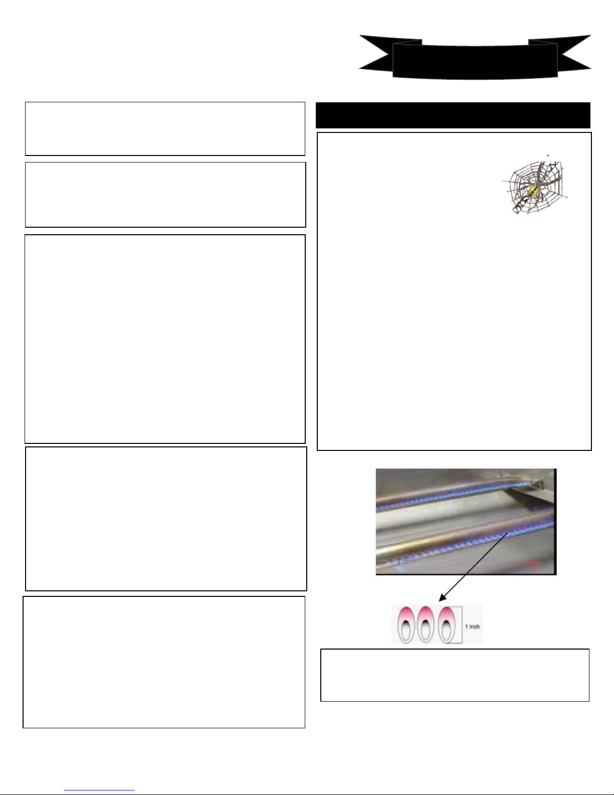
CAUTION: Beware of Flashback
CAUTION: Spiders and small insects occasionally
spin webs or make nests in the grill
burner tubes during transit and
warehousing. These webs can lead
to gas flow obstruction, which could
result in a fire in and around burner
tubes. This type of fire is known as
“FLASH-BACK” and can cause serious damage to
your grill and create an unsafe operating condition for
the user.
Although an obstructed burner tube is not the only
cause of “FLASH-BACK”, it is the most common
cause.
To reduce the chance of “FLASH-BACK”, you must
clean the burner tubes before assembling your grill,
and at least once a month in late summer or early fall
when spiders are most active. Also perform this
burner tube cleaning procedure if your grill has not
been used for an extended period of time. A clogged
tube can lead to a fire beneath the grill.
If an external electrical source is utilized: The outdoor
cooking gas appliance, when installed, must be
electrically grounded in accordance with local codes or,
in the absence of local codes, with the National Electrical
Code, ANSI/NFPA 70, or the Canadian Electrical Code,
CSA C22.1.
WARNING
Keep any electrical supply cord and the fuel supply hose
awa
from anyheated surfaces.
NOTE: The normal flow of gas through the regulator and
hose assembly can create a humming noise. A low
volume of noise is perfectly normal and will not interfere
with operation of the grill. If humming noise is loud and
excessive you may need to purge air from the gas line or
reset the regulator excess gas flow device. This purging
procedure should be done every time a new LP gas tank
is connected to your grill.
INSTALLATION INSTRUCTIONS
Visually check the burner flames prior to each use. The
flames should look like this picture. If they do not,
refer to the burner maintenance part of this manual.
5
Page 6
Gas Supply Requirements
Installation of this grill must conform with local codes, or in the absence of local codes, the
national Fuel Gas Code, ANSIZ223.1 / NFPA 54. In Canada, installation must conform to the
current natural Gas Installation /code, CAN 1-1.1-M81 and with local codes where applicable.
This grill has been design-certified according to ANSIZ21.1a, latest edition.
MINIMUM GAS SUPPLY PRESSURE TO APPLIANCE FOR LP GAS---11.0 IN.W.C.
MINIMUM GAS SUPPLY PRESSURE TO APPLIANCE FOR NG ---7.0 IN.W.C.
APPLIANCE REGULATOR IS SET AT 4.0 IN. W.C. OUTLET PRESSURE.
Keep appliance area clear and free from combustible materials, gasoline, and other flammable
vapors.
Do not obstruct the flow of combustion air into the grill and ventilation air away from the grill.
Before installing the grill, make sure to use the right gas supply.
Safety Instruction
For appliances designed to use a CGA 791 Connection:" Place dust cap on cylinder valve outlet
whenever the cylinder is not in use. Only install the type of dust cap on the cylinder valve outlet that
is provided with the cylinder valve. Other types of caps or plugs may result in leakage of propane."
Theapplianceshallnotbeusedforspaceheating.Thisinformationisbasedonsafety
considerations. All openings in the wall behind the appliance and in the floor under the
appliance shall be sealed.
6
Page 7
Safety Instruction
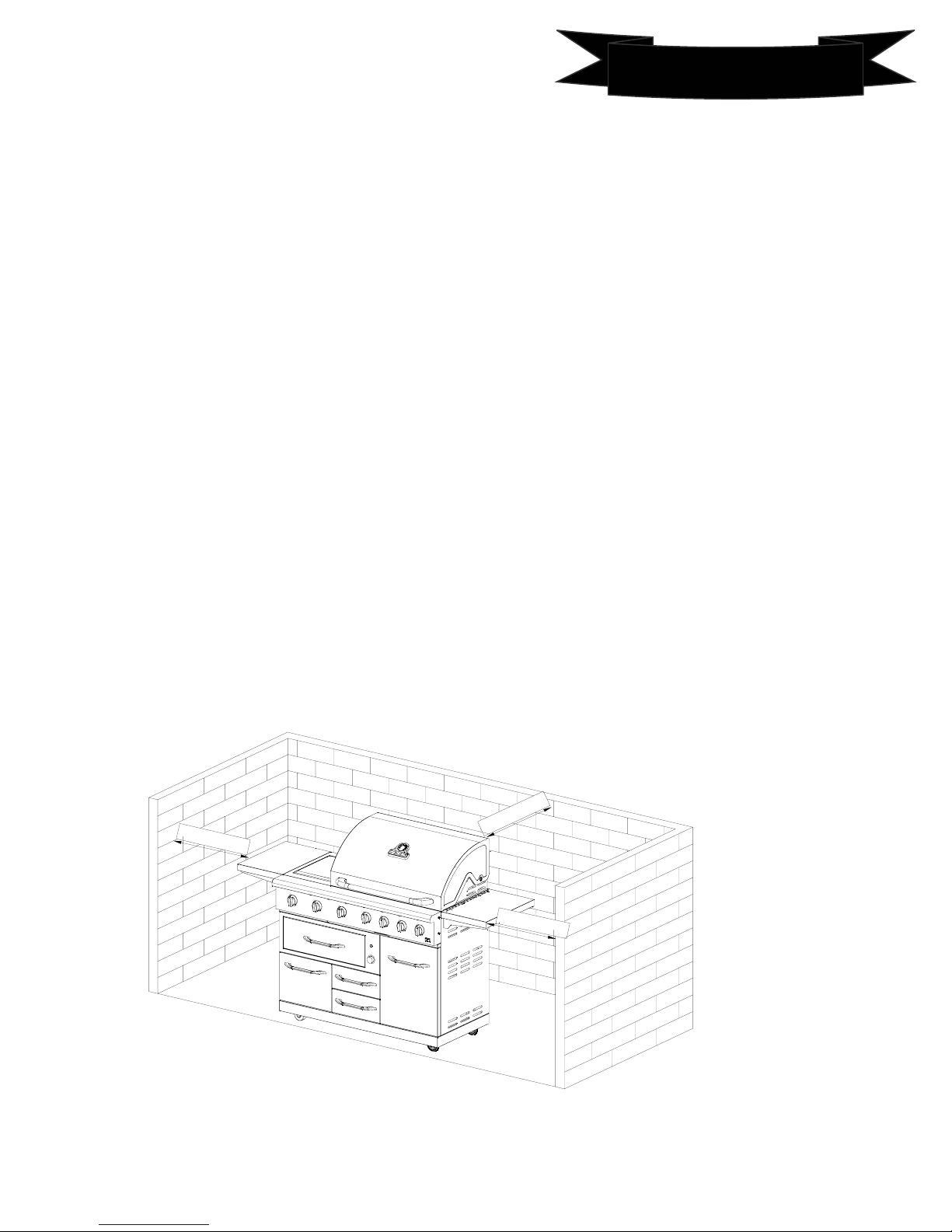
PROPER PLACEMENT AND CLEARANCE OF GRILL
•Never use your gas grill in a garage, porch, shed, breezeway or any other enclosed area. Your gas grill is to be
used outdoors only.
•Do Not install this unit into combustible enclosures.
•Minimum clearance from sides and back of unit to combustible construction, 24 inches (61 cm) from sides and 24
inches (61 cm) from back.
•DO NOT use this appliance under overhead combustible surfaces. This outdoors cooking gas appliance is not
intended to be installed in or on recreational vehicles and/or boats.
•Do Not obstruct the flow of ventilation air around the gas grill housing. Only use the regulator and the hose
assembly supplied with your gas grill. Replacement regulators and hose assemblies must be those specified in this
manual.
•The regulator and hose assembly must be inspected before each use of the grill. If there is excessive
abrasion or wear or if the hose is cut, it must be replaced prior to the grill being put into operation. The
replacement hose assembly shall be that specified by the manufacturer.
•Pressure regulator and hose assembly supplied with the outdoor cooking gas appliance must be used. Never
substitute other types of regulator. Contact customer service for manufacturer specified replacement parts.
•This outdoor cooking gas appliance is equipped with a pressure regulator that complies with the standard for
Pressure Regulating Valves for LP Gas ANSI/ UL 144.
•Do not use briquettes of any kind in the grill.
•Keep the back and side cart free and clear from debris. Keep any electrical supply cord or the rotisserie motor
cord away from the heated areas of the grill.
•Never use the grill in extremely windy conditions. If located in a consistently windy area (oceanfront,
mountaintop, etc.) a windbreak will be required. Always adhere to the specified clearance.
•Never use a dented or rusty propane tank.
•Keep any electrical supply cord and the fuel supply hose away from any heated surface
•While lighting, keep your face and hands as far away from the grill as possible.
•Burner adjustment should only be performed after the burner has cooled.
2
4
i
n
c
h
e
s
s
e
h
c
in
4
2
2
4
i
nc
h
e
s
7
Page 8

Safety Instruction
Use a covered hand when opening the grill lid.
Never lean over an open grill.
When lighting a burner, pay close attention to what
you are doing. Make sure you are aware of which
burner you are lighting, so your body and clothing
remain clear of open flames
Grease is flammable. Let hot grease cool before
attempting to handle it. Do not allow grease deposits
to collect in the grease tray at the bottom of the grill’s
firebox. Clean the grease tray often.
Do not use aluminum foil to line the grill racks or grill
bottom. This can severely upset combustion air flow or
trap excessive heat in the control area.
For proper lighting and performance of the burners
keep the burner ports clean. It is necessary to clean
them periodically for optimum performance. The
burners will only operate in one position and must be
mounted correctly for safe operation.
.
Do not use the grill to cook excessively fatty meats or
other products which promote flare – ups.
Keep the area surrounding the grill free from
combustible materials including fluids, trash, and
vapors such as gasoline or charcoal lighter fluid. Do
not obstruct the flow of combustion and air
ventilation
Clean the grill with caution. To avoid steam burns, do
not use a wet sponge or cloth to clean the grill while it
is hot. Some cleaners produce toxic fumes or can
ignite if applied to a hot surface.
Turn off grill controls and make certain the grill is cool
before using any type of aerosol cleaner on or around
the grill. The chemical that produces the spraying
action could, in the presence of heat, ignite or cause
metal parts to corrode.
8
Page 9

Safety Instruction
Electric Power Supply Requirements
Your grill must be electrically grounded in accordance with local codes, or in the absence of
local codes, in accordance with the National Electrical Code (ANSI/NFPA 70, latest edition).
In Canada, electrical grounding must be in accordance with the current CSA C22.1 Canadian
Electrical Code Part 1 and/or local codes. A copy of this standard may be obtained from:
National Fire Protection Association, 1 Battery march Park, Quincy, Massachusetts
02269-9101.
The power supply must be the correct polarity. Reverse polarity will result in continuous
sparking of the electrodes, even after flame ignition. If there is any doubt as to whether the
power supply has the correct polarity or is grounded, have it checked by a qualified
electrician.
Use 120V, 60Hz, and properly grounded branch circuit protected by a 15-amp or 20-amp
circuit breaker or time delay fuse.
Outdoor cooking gas appliances provided with electrical equipment shall have the following
included in the instructions.
Instruction for electrical equipment, separately approved by a nationally recognized
testing agency, that is required to be provided with instructions for use shall be included with
the instructions required with an outdoor cooking gas appliance. This can be in its original
form or duplicated within the instructions provided with the outdoor cooking gas appliance.
1. To protect against electric shock, do not immerse cord or plugs in water or other liquid.
2. Unplug from the outlet when not in use and before cleaning. Allow to cool before putting
on or taking off parts.
3. Do not operate any outdoor cooking gas appliance with a damaged cord, plug, or after the
appliance malfunctions or has been damaged in any manner. Contact the manufacturer for
repair.
4. Do not let the cord hang over the edge of a table or touch hot surfaces.
5. Do not use an outdoor cooking gas appliance for purposes other than intended.
6. When connecting, first connect plug to the outdoor cooking gas appliancethenplug
appliance into the outlet.
Safety Instruction
9
Page 10
Safety Instruction
7. Use only a Ground Fault Interrupter (GFI) protected circuit with this outdoor cooking gas
appliance.
8. Never remove the grounding plug or use with an adapter of 2 prongs.
9. Use only extension cords with a 3 prong grounding plug, rated for the powerofthe
equipment, and approved for outdoor use with a W-A marking.
10
Page 11

ELECTRICAL GROUNDING INSTRUCTIONS
k
Safety Instruction
IMPORTANT
This outdoor cooking appliance is equipped with a three-prong (grounding)plugforyour
protection against shock hazard and should be plugged directly into a properly grounded
three-pronged receptacle. DO NOT
cut or remove the grounding prong from this plug.
INSTALLATION INSTRUCTIONS
To ensure proper and safe operation, read all instructions before using theproduct.Installor
locate the product only in accordance with the provided Installation Instruction.
•
Do not attempt to adjust, repair, service or replace any part of your appliance unless it is
specifically recommended in this guide.
• Do not use the warming drawer for heating.
•
Do not leave children alone or unattended in the area where the gas grill is inuse.Donot
sit or stand on any part of the grill and the warming drawer. Do not let children play with
the grill.
•
All servicing should be referred to a qualified technician.
•
Have the technician show you the location of the gas shut off valve and how to shut it off
in an emergency situation. (For LP please see page 15, For NG please see Page 24 for how
to shut off the gas.)
• Always disconnect power to appliance before any type of servicing.
• Do not use abrasive or caustic cleaners or detergents on this appliance. They may cause
permanent damage to the surface.
•
When cooking, set the burner controls so that the flame heats only the bottomofthe
utensil and does not overlap at the sides of the utensil.
• Utensils (pots and pans) that conduct heat slowly, i.e. glass pots, should be used in
conjunction with burner flames at a low or medium setting.
•
Turn off all controls and wait for appliance parts to cool down before touching them. Do
not touch the burner grates or surrounding areas until cool.
•
Do not use water on grease fires.
•
Always turn pot handles to the side or bac
area where they are easily burned. Handles should not extend over the adjacent burners.
•
Use the grill only for cooking tasks as outlined in this manual. When using the grill, do not
touch the grates, burner caps, burner bases, or any other parts in proximitytotheflame.
These components may be hot enough to cause burns.
• Use dry pot holders. Moist or damp pot holders on hot surfaces may result in burns from
steam.
•
Do not let pot holder touch hot surface areas.
• Do not use a towel or other bulky cloth.
• Do not heat unopened food containers. Build up of pressure may cause the container to
explode and result in injury.
•
During and after use, do not touch interior surfaces of the oven until cool.
of the grill. Do not turn handles towards the
11
Page 12
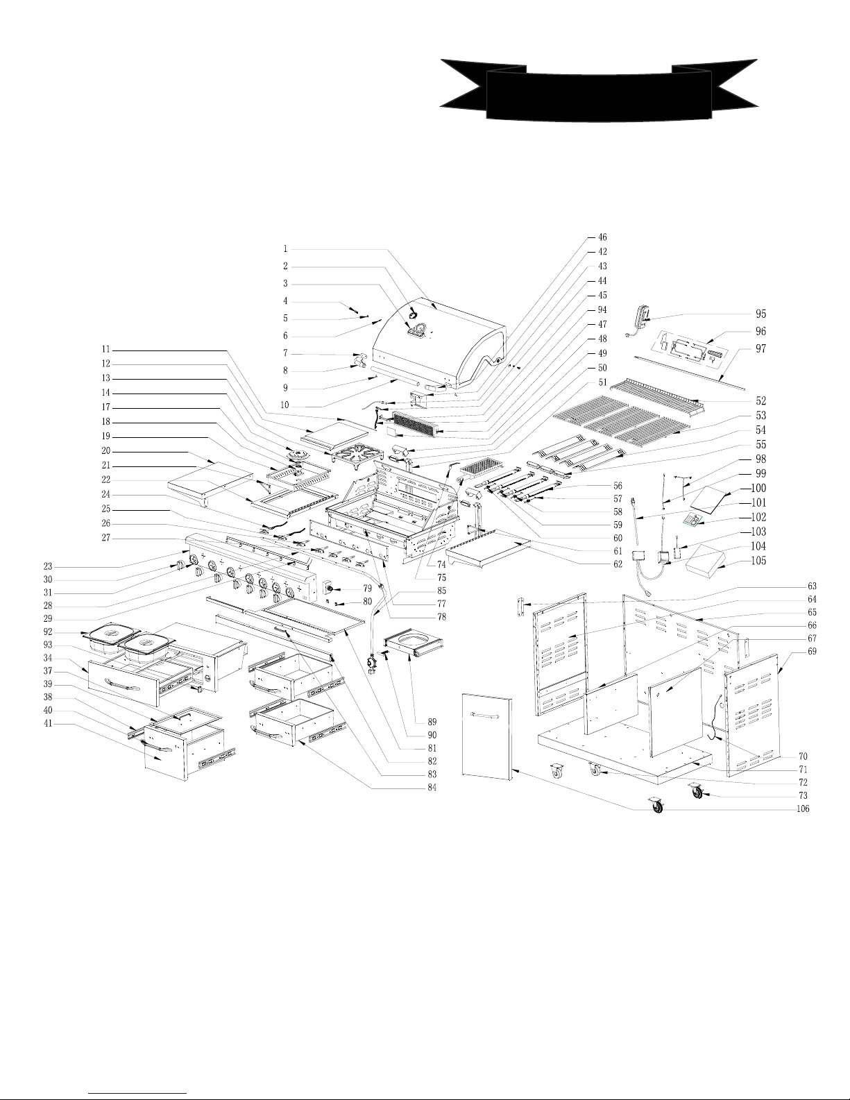
Exploded View
LP/NG Convertible Gas Grill Parts Diagram
12
Page 13
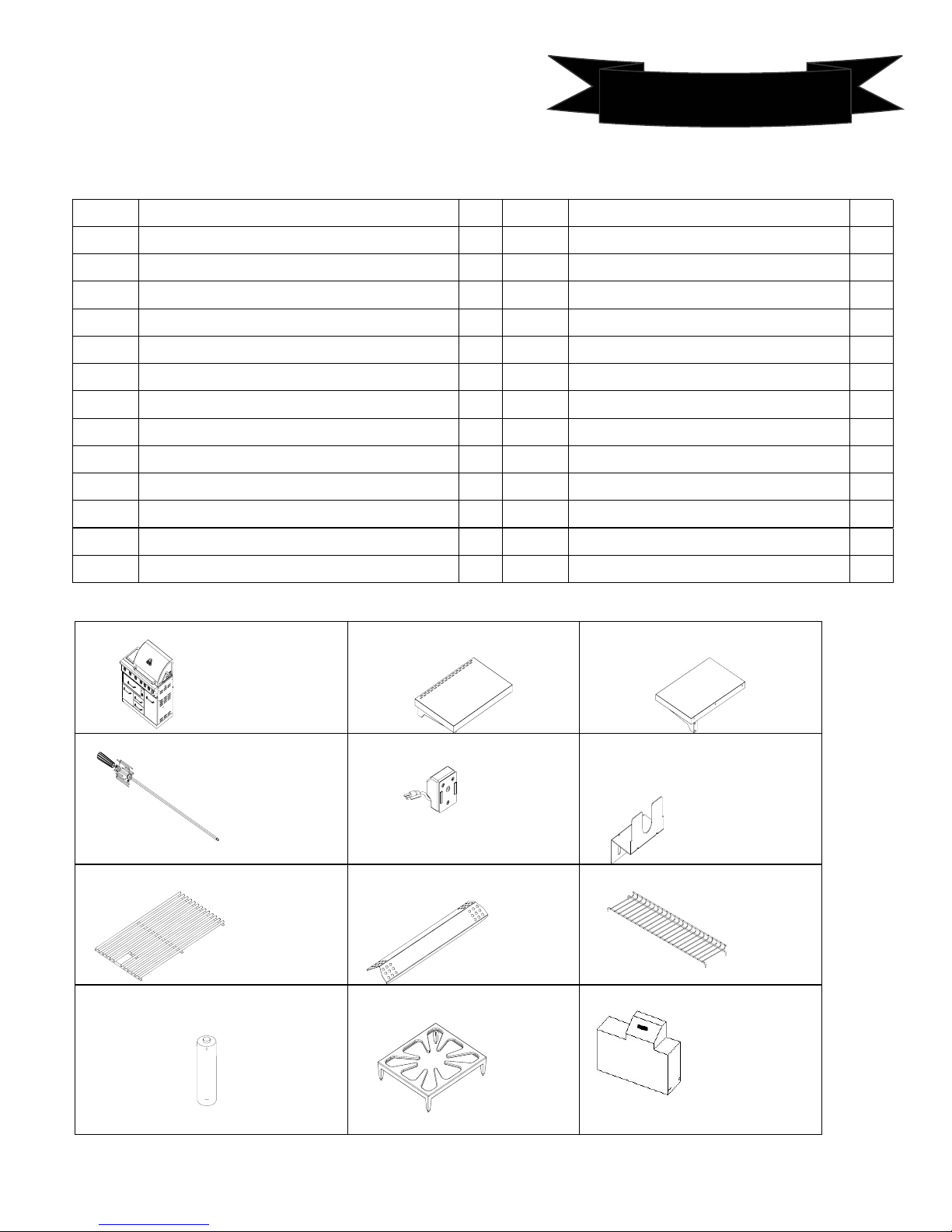
Parts List
Parts List
LP/NG Convertible Gas Grill Parts List
Part NO. English name Qty Part NO. English name Qty
1
2
3
4
5
6
7
8
9
10
11
12
13
14
Main lid 1
Temperature gauge 1
Logo/temperature gauge seat 1
Main lid hinge bolt 2
Mail lid screw 2
Main lid hinge rod 2
Main lid Handle heat insulating 2
Main Lid Handle Seat left 1
Cushion rubber 2
Main Lid Handle 1
Side Burner Lid Hinge Rod 1
Side Burner Lid 1
Side burner Iron cooking grate 1
Side Burner Head 1
54
55
56
57
58
59
60
61
62
63
64
65
66
67
Flame tamers 4
Fire cross 1
Main burners 4
Main Burner ignitor Wire A 1
Main Burner ignitor Wire B 1
Main Burner ignitor Wire C 1
Main Burner ignitor Wire D 1
Side shelve support right 1
Side shelve right 1
Control panel support piece 2
Cart side panel left 1
Cart rear panel 1
Cart division plate A 1
Cart division plate B 1
17 Side Burner base installation Ring 1 69 Cart side panel right 1
18
19
Side burner base with orifice 1
Side Burner fire box 1
70
71
Lighting rod 1
Cart bottom panel 1
20
21
22
23
24
25
26
27
28
29
30
31
34
37
38
39
Side shelve left 1
Side shelve support left 1
Side Burner fire box assembly frame 1
Control panel 1
Side burner gas Valve 1
Rear burner gas Valve 1
Searing burner gas valve 1
Main burner gas valve 4
Gas supply manifold 1
LED Lamp cord& LED light 1
Control knob 7
Control knob bezel 7
Warming drawer assembly 1
Cooler box cover handle 1
Cooler/drawer slide 4
Cooler box cover 1
72
73
74
75
77
78
79
80
81
82
83
84
85
89
90
92
3”Caster 2
3”Caster swivel 2
Searing burner 1
Searing burner ignitor wire 1
Control panel heat shield 1
Fire box 1
Electric ignitor module 1
LED/Halogen light switches 2
Grease tray 1
Crossbeam 1
Grease tray handle 1
Storage drawers 2
LP regulator 1
Gas Tank slide 1
Gas tank tighten screw 1
Warming drawer inner pans 2
13
Page 14
Parts List
Parts List
LP/NG Convertible gas grill Parts list
Parts List
40
Handle 5
41
Cooler 1
42
Rear burner ignitor wire & orifice cover 1
43
Rear burner Thermocouple 1
44
Rear burner orifice 1
45
Rear burner ignitor wire 1
46 Main Lid Handle Seat right 1
47
Rear burner 1
48
Rear burner Baffle 1
49
Halogen light cover
50
Halogen light 2
51
Halogen light wire protector 2
52
Warming rack 1
53
Cooking grates 3
PACKAGE CONTENTS LIST
1. Firebox Assembly ------------1pcs. 2. Left Side Shelf ----------1pcs. 3. Right Side Shelf-----------1pcs.
2102
93
94
95
96
97
98
99
100
101
103
104
105
106
Warming drawer control knob 1
Rear burner gas corrugated gas pipe 1
Rotisserie motor 1
Rotisserie kits 1
Rotisserie rod 1
Halogen lights wire 1
Halogen lights switch wire 1
Manual 1
Power supply wire 1
Hardware bag 1
Led Battery box 1
Transformer kit 1
Grill cover package 1
Grill tank door 1
4. Rotisserie kits -----------------1pcs. 5. Motor-----------------------1pcs.
7. Cooking grid -------------------3pcs.
9. 1.5 Volt “AA” Size Alkaline
Battery--------------------------------3pcs.
8. Frame tamer------------4 pcs. 9. Warning rack ------------1pcs.
8. Side burner Iron cooking
grate------------------------1 pcs.
14
6. Rotisserie bracket
------------------------------------1pcs.
8. Pvc cover------------------1pcs.
Page 15

Assembly Instruction
Please read the instructions carefully and follow step by step.
Tools required: Philips head screwdriver -(not provided).
Parts list: Grill main body, left side shelf, right side shelf, rotisserie bracket, cooking grid,
flame tamer, warming rack.
1. SIDE SHELF ASSEMBLY
①The screws used to attach the side shelf are already screwed into the left side burner and right sides
panel (see the figure below). Loosen the screws from the left side burner and right side panel, install
the side shelves and tighten screws as the two figures show below.
②The screws used to attach the triangular support frame are already screwed into the side shelf.
Attention:
a. The upper 2 screws to the right firebox panel should be screwed from inside to outside for
side shelf
b. The screws below them should be tightened from outside into inside.
15
Page 16

Assembly Instruction
Assembly Instruction
2. Fit the flame tamers between the notches inside the firebox. Insert warming rack and cooking
grids as shown in the figure below.
Assembly Instruction
3. Loosen the 2 screws which are pre-placed on rotisserie bracket, then tighten the bracket into the
grill fire box side panel, and insert the rotisserie motor and skewer.
Warning: Tighten all screws on grill as some may have loosened during transit
16
Page 17

Assembly Instruction
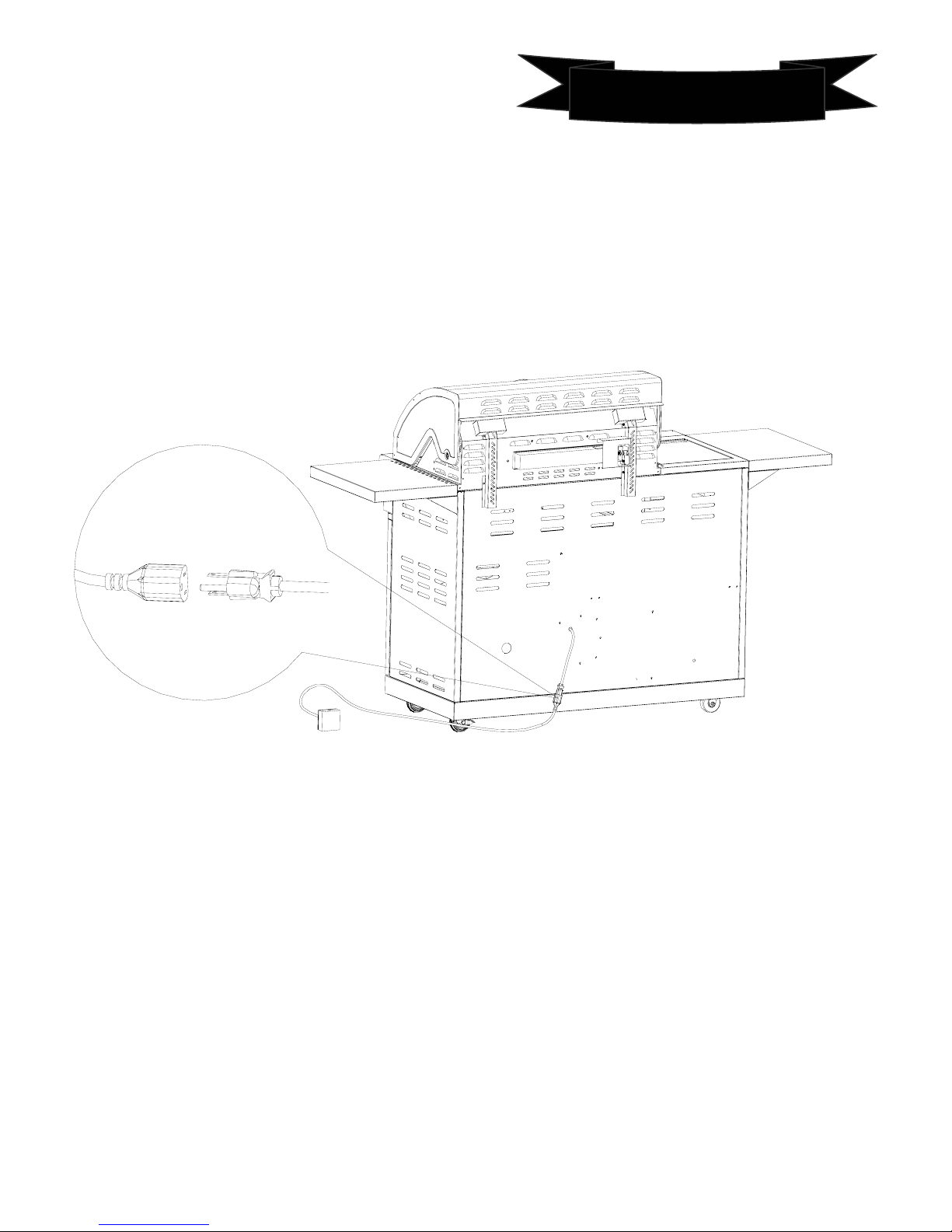
Grounding
1. The power cord is equipped with a three-prong (grounding) plug which mates with a
standard three-prong grounding wall receptacle to minimize the possibility of electrical
shock hazard from the grill.
2.
All cord connected appliances shall include instructions relative to location of the wall
receptacle and a warning to the user to disconnect the electrical supply before serving the
appliance.
3.
Where a standard two-prong wall receptacle is encountered, it is the responsibility and
obligation of the customer to have it replaced with a properly grounded three-prong wall
receptacle. Do not cut or remove the grounding prong from the power cord.
Connect Grill to Gas Supply
Liquid Propane gas supply connection:
① Raise the gas tank retention ring located inside the cart on the right panel. Secure the
ring to the ring bracket. Place gas tank into the gas tank hole. Release the gas tank
retention ring and place the ring over the gas tank ensuring the gas tank is secured.
② Then tighten up the gas tank retention kit for fixing the gas tank as shown inthebelow.
The hose should be
place into the by the
hose ring which is
located inside of the
cart right side panel.
Assembly Instruction
17
Page 18

LP Gas Hook-up
NEVER CONNECT AN UNREGULATED GAS SUPPLY LINE TO THE APPLIANCE. USE THE
REGULATOR/HOSE ASSEMBLY SUPPLIED
Liquid Propane gas
For liquid propane configured grill. Do not attempt to
use a natural gas supply.
Total gas consumption (per hour) of this stainless
steel gas grill with all burners on “MAX”:
Main burner 40,000 Btu/hr.
Sear burner 15,000 Btu/hr
Side burner 13,000 Btu/hr
Rear burner 12,000 Btu/hr
Total 80,000 Btu/hr.
L.P. TANK REQUIREMENT
A dented or rusty L.P. tank may be hazardous and
should be checked by your L.P. supplier. Never use a
cylinder with a damaged valve. The L.P. gas cylinder
must be constructed and marked in accordance with
the specifications for L.P. gas cylinders of the U.S.
Department of Transportation (DOT) or the National
Standard of Canada, CAN/CSA-B339, Cylinders,
Spheres and Tubes for Transportation of Dangerous
Goods; and Commission, as applicable. Overfilling
prevention device (OPD) shall be provided on cylinder
& QCCI connection on the cylinder valve,
ANSI/CGA-V-1. The cylinder supply system must be
arranged for vapor withdrawal. Make sure tank is
leveled with bottom panel for proper vapor withdraw.
The cylinder must include a collar to protect the
cylinder valve. The cylinder must be provided with a
shut off valve terminating in an L.P. gas supply
cylinder valve outlet specified, as applicable, for
connection type QCC1 in the standard for compressed
gas cylinder valve outlet and inlet connection
ANSI/CGA-V-1.
Manifold pressure: 28cm(11 inches) water column
(W.C.).
L.P. GAS HOOK-UP
Ensure that the rubber “ O” Ring on the LP cylinder
valveareinplaceandthatthehosedoesnotcome
into contact with the grease tray or the grill head. Set
the liquid propane gas cylinder into the slide-out tray
making sure that the cylinder is level with the bottom
panel, thus allowing proper vapor withdrawal.
CONNECTION
Your stainless steel grill is equipped with gas supply
orifices for use only with liquid propane gas. It is also
equipped with a high capacity hose/regulator
assembly for connection to a standard 20lb. L.P.
cylinder 46.35cm (18-1/4 in.) high, 31mc(12-1/4 in.)
diameter. To connect the L.P. gas supply cylinder,
please follow the steps below:
1. Make sure tank valve is in its full off position (turn
clockwise to stop)
2. Check tank valve to assure it has proper external
male threads (type 1 connection per ANSIZ21.81)
3.Makesureallburnervalvesareintheiroffposition.
4. Inspect valve connections, port, and regulator
assembly. Look for any damage or debris. Remove
any debris. Inspect hose for damage. Never attempt
to use damaged or obstructed equipment. Contact
your local L.P. gas dealer for repair.
18
LP Gas Hook-up
Page 19

LP Gas Hook-up
5. When connecting regulator assembly to the valve,
hand tighten the quick coupling nut clockwise to a
complete stop. Do not use a wrench to tighten. Use
of a wrench may damage the quick coupling nut and
result in a hazardous condition.
6. Open the tank valve fully (counterclockwise). Use a
soapy water solution to check all connections for
leaks before attempting to light the grill, see below. If
a leak is found, turn the tank valve off and do not use
the grill until a local L.P. gas dealer can make repairs.
To disconnect L.P. gas cylinder:
1. Turn the burner valves off.
2. Turn the tank valve off fully (turn clockwise to stop).
3. Detach the regulator assembly from the tank
valve by turning the quick coupling nut
counterclockwise.
INSTALLER FINAL CHECK LIST
√ Specified clearance maintained 24”(61cm) from combustibles.
√ All internal packaging removed.
√Knobsturnfreely.
√ Burners are tight and sitting properly on orifices.
√ Pressure regulator connected and set. Gas connections to grill using hose & regulator assembly
provided (pre-set for 11.0”water column).
√ Unit tested and free of leaks.
√ User informed of gas supply shut off valve location
PROPANE CYLINDER CAUTIONS
a) Do Not store a spare LP-gas cylinder under or near this appliance.
b) NEVER fill the cylinder beyond 80 percent full.
c) If the information in “a” and “b” is not followed exactly, a fire causing death or serious
injury may occur.
USER, PLEASE RETAIN THIS MANUAL FOR FUTURE REFERENCE.
19
Page 20

Liquid Propane Gas LEAK TESTING
LP Leak Testing
GENERAL
Although all gas connections on the grill are leak
tested at the factory prior to shipment, a
complete gas tightness check must be
performed at the installation site due to possible
mishandling in shipment, or excessive pressure
unknowingly being applied to the unit.
Periodically check the whole system for leaks
following the procedures listed below. If the
smell of gas is detected at anytime you should
immediately check the entire system for leaks.
BEFORE TESTING
Make sure that all packing material is removed
from the grill including the burner tie-down
straps.
DO NOT SMOKE WHILE LEAK TESTING.
NEVER PERFORM LEAK TEST WITH AN OPEN
FLAME.
Make a soap solution of one part liquid
detergent and one part water. You will need a
spray bottle, brush, or rag to apply the solution
to the fittings. For the initial leak test, make sure
the L.P. cylinder is full.
TO TEST
1. Make sure the control valves are in the OFF
position, and turn on the gas supply.
2. Check all connections from the LP gas
regulator and supply valve up to and including
the connection to the manifold pipe assembly
(the pipe that goes to the burners). Soap
bubbles will appear where a leak is present.
3. If a leak is present, immediately turn off the
gas supply and tighten the leaky fittings.
4. Turn the gas back on and recheck.
5. Should the gas continue to leak from any of
the fittings, turn off the gas supply and contact
customer service at 1-877-639-7264, 9 a.m. - 5
p.m., PST, Monday-Friday. English, French, and
Spanish representatives are available.
Only those parts recommended by the manufacturer
should be used on the grill.
Substitution will void the warranty. Do not use the
grill until all connections have been checked and do
not leak.
GAS FLOW CHECK
Each grill burner is tested and adjusted at the factory
prior to shipment; however, variations in the local gas
supply may make it necessary to adjust the burners.
The flames of the burners should be visually checked.
Flames should be blue and stable with no yellow tips,
excessive noise or lifting. If any of these conditions
exist, check to see if the air shutter or burner ports
are blocked by dirt, debris, spider webs, etc. If you
have any questions regarding flame stability, please
call customer service at 1-877-639-7264, 9a.m. 5p.m., PST, Monday - Friday. English, French, and
Spanish representatives are available.
ALWAYS CHECK FOR LEAKS AFTER EVERY L.P.
TANK CHANGE
Check all gas supply fittings for leaks before each
use. It is handy to keep a spray bottle of soapy
water near the shut-off valve of the gas supply line.
Spray all the fittings. Bubbles indicate leaks.
Regulator connects to the gas
tank.
Regulator connects to valve
manifold.
20
Page 21

NG Gas Conversion
IMPORTANT: The Natural gas Conversion Kit (see next page parts list) supplied with this grill must be
used. If you want to convert to local NG gas supply, contact your local gas company for specific
instructions. Conversion must be installed by a qualified gas technician.
Natural Gas requirements:
Operating pressure: 4” (10.2 cm) WCP
Inlet (supply) pressure: 7” to 14” (17.8 cm to 35.5 cm) WCP maximum. Contact local gas supplier if you are
not sure about the inlet (supply) pressure.
This installation must conform with local codes and ordinances. In the absence of local codes, installations
must conform with either the National Fuel Gas Code ANSI Z223.1 - latest edition, or CAN/CGA-B149.1
Natural Gas and Propane installation code. Copies of the standards listed above may be obtained from:
1. CSA International, 8501 East Pleasant Valley Rd. Cleveland, Ohio 44131-5575
2. National Fire Protection Association One Battery march Park Quincy, Massachusetts 02269
NG conversion procedure:
NG kit Parts list:
Part
Description Quantity Remarks
NO.
1
NG Orifice, Main burner (∅1.5mm)
2 NG Orifice, Searing burner(∅1.8mm)
3
NG Orifice, Side burner(∅1.76mm)
4
NG Orifice, Rear burner(∅1.7mm)
5
flat-blade screwdriver
6
NG regulator
7
10FT NG hose with 2 connectors
4 pcs included
1 pc included
1 pc included
1pc included
1pc included
1pc
1pc
Not included,
Purchase separately.
Not included,
Purchased separately.
Tools needed (No included)
1. Phillips screwdriver 2.Adjustable wrench 3. 6mm socket and wrench or 6mmnutdriver
4. Thin flat-blade screwdriver
21
Page 22

NG Gas Conversion
STEP ONE: Disconnect the LP gas supply system
1. Turn off all burner control valves.
2. Clockwise turn off the main gas supply valve.
3. Disconnect 20 lb LP gas fuel tank (if present) and remove the 20 lb LP gas fuel tank from the grill
cabinet.
4.UseanadjustablewrenchtoremovetheLPregulatorfromthemanifold.Asbelow picture.
Disconnect the rigid pipe or semi-rigid tubing or connector which connectstothemanifold.
22
Page 23

NG Gas Conversion
NG Gas Conversion
STEP TWO: Open the conversion kit to check the part list
STEP THREE: Change Grill Main Burner Valve Orifices
1. Remove the grates and flame tamers.
2. Remove the 1 screw that holds the burner in place. Set the screws aside. Remove the burner
from the grill by lifting the burner out.
23
Page 24

NG Gas Conversion
3.
Use a 6 mm socket wrench or 6 mm nut driver to remove the brass orifice from the end of gas
valve.PlacetheNGorificeintotheendofgasvalve,the4mainburnersorificeholeØare1.5mm
(Part No. 1). The searing burner orifice hole Ø is 1.8mm (Part No. 2).
4.
Reinsert the burner and reattach using the screw previously removed. Repeat the procedure
for each main burners and Searing burner.
IMPORTANT: Check that the burner is properly installed inside of the gas valve.
5. Position the ignitor pin so they are
1/5” (4-5 mm)
away from each burner.
STEP FOUR: Change Grill Side Burner Valve Orifices
1. Remove the side burner grid and side burner head.
2.
Use a 6 mm socket and wrench or 6 mm nut driver to remove the brass orifice from the end of gas
valve. Place the side burner NG orifice into the end of gas valve (side burner NG orifice hole Ø is
1.78mm, Part No. 3).
Warning: Please make sure all the orifices are installed properly.
24
Page 25

NG Gas Conversion
STEP FIVE: Change the Rotisserie/Infrared Burner Orifice
1.
Using a Phillips screw driver, remove the 3 screws and remove the rotisserie/infrared burner wind
baffle.
2. Use wrench to remove the nut on the orifice base.
25
Page 26

NG Gas Conversion
3. Remove LP orifice, then install the Rear burner NG orifice (side burner NG orifice hole Ø is
1.7mm)( Part 4)
MPORTANT: Check that the orifice is properly installed then put on the base nut and install the
wind baffle.
STEP SIX: adjust the valve to NG Setting.
1. Using a hexagon wrench (provided together with the manual bag), remove the 5pcs knobs (searing
burner & rear burner do not need adjusting.)
Using the flat-blade screwdriver (NG kit part 5), adjust the valve setting from LP to NG by
clockwise turning approximate 90 degrees. (If you want to change back to LP setting, please
counterclockwise turn approximate 90 degrees).
26
Page 27

NG Gas Hook-up
STEP SEVEN:Connecting the NG hose
Natural Gas Supply
For natural gas configured grill. Do not attempt to use a liquid propane supply.
Total gas consumption (per hour) of this stainless steel gas grill with all burners on “MAX”:
Main burner 40,000 Btu/hr.
Sear burner 15,000 Btu/hr
Side burner 13,000 Btu/hr
Rear burner 12,000 Btu/hr
Total 80,000 Btu/hr.
IMPORTANT: The supply line shall be equipped
with an approved shutoff valve. This valve should
be located in the same area as the grill and should
be in a location that allows ease of opening and
closing. Do not block access to the shut off valve.
The valve is for turning on or shutting off gas to
the grill.
1. Connect the NG regulator to the Grill (NG
regulator are not included).
2. Connect the brass connector of the 10 ft (3
m) PVC flexible gas supply hose to the
Natural gas pressure regulator.
NOTE: the 10 ft (3 m) PVC flexible gas supply
hose design-certified by CSA must be used.
Pipe-joint quick connector suitable for
Nature gas must be used. Do not use Teflon
tape.
3. Install the NG quick connector to the NG
supply pipe by a qualified gas technician.
4. Connect the 10 ft (3 m) PVC flexible gas
supply hose to the rigid Natural gas supply
pipe。(The 10 ft (3 m) hose not included).
Warning: NG Conversion must be installed
by a qualified gas technician.
NG regulator
27
Page 28

Natural Gas LEAK TESTING
NG Leak Testing
1. Open the manual shutoff valve in the
gas supply line. The valve is open
when the handle is parallel to the gas
pipe.
2. Test all connections by brushing
on an approved noncorrosive
leak-detection solution. Bubbles
will show a leak. If a leak is found,
turn the NG gas valve off and do
not use the grill. Contact a
qualified gas technician to make
repairs.
3. The ignitor batteryis not factory installed.
An “AA” size alkaline battery is located in
the accessory box on the grill grate. Install
battery at this time following the
instructions in“Replacing the ignitor
Battery”section. (The battery is included)
4. The NG regulator is adjusted by
manufacture,no need to make any
adjustment.
5. Check and adjust the burners.
6. Remove the CSA LP label in the door and
put on the CSA NG label.
Record Conversion:
The model/serial number plate is located on
the right-hand side of the grill. With a
permanent marker, check the box next to
“Natural gas” and mark through “LP.” In
the last page of the Use and Care Guide, write
“Converted to Natural Gas.” Also record the
conversion date and the technician/company
that performed the conversion. NOTE: keep
with package containing the literature.
Please stick this label on door inside after
converted to Natural Gas:
This grill has been converted to use Natural Gas.
For use with a gas appliance pressure regulator.
The orifices in this NG CONVERSION KIT are used
to convert the LP unit to NG unit.
28
Page 29

Operating Instruction
GENERAL USE OF THE GRILL AND ROTISSERIE
Each main burner is rated at 10,000 Btu/hr. The main grill burners encompasstheentirecookingarea
and are side ported to minimize blockage from falling grease and debris. Above the burners are
stainless steel radiant flame tamers. The ignitor knobs are located on the lower center portion of the
valve panel. Each rotary ignitor is labeled on the control panel.
USING THE GRILL
Grilling requires high heat for searing and proper browning. Most foods arecookedatthe “HI” heat
setting for the entire cooking time. However, when grilling large pieces ofmeatorpoultry,itmaybe
necessary to turn the heat to a lower setting after the initial browning. This cooks the food through
without burning the outside. Foods cooked for a long time or foods basted with a sugary marinade
may need a lower heat setting near the end of the cooking time.
NOTE: The hot grill sears the food, sealing in the juices. The longer the preheat, the faster the meat
browns and the darker the grill marks.
DO NOT LEAVE THE GRILL UNATTENDED WHILE COOKING.
CAUTION: PLEASE TAKE OFF THE WARMING RACK WHEN USING THE
REAR BURNER. THE HIGH HEAT COMING FROM THE REAR BURNER MAY
CAUSE THE WARMING RACK TO BEND.
29
Page 30

Grill Lighting Instruction
p
WARNING: IMPORTANT!
USING THE SIDE BURNER:
Inspect the gas supply hose prior to turning the gas“MAX”. If there is evidence of cuts, wear or abrasion, it must be
replaced prior to use. Do not use the side burner if the odor of gas is present.
USING ROTISSERIE BURNER
Your grill is capable of performing back burner rotisserie cooking once lit. The rotisserie burner will reach cooking
temperatures in about 1 minute.
WARNING: IMPORTANT!
BEFORE LIGHTING…
Inspect the gas supply hose prior to turning the gas
“MAX”. If there is evidence of cuts, wear, or abrasion,
it must be replaced prior to use. Do not use the grill if
the odor of gas is present. Only the pressure regulator
and hose assembly supplied with the unit should be used.
TO LIGHT THE GRILL BURNER:
Make sure all knobs are “OFF” then turn on the gas
supply from the LP tank. Always keep your face and
body as far from the grill as possible when lighting.
Your stainless steel grill has an exclusive patented
built-in ignition. The ignitor is built in to the valve. To
ignite each burner simply push and turn the control
knobs to the MAX setting, you will hear the valve click as
it sends a spark to the pilot flame. If the burner does
not light wait 5 minutes for any excess gas to dissipate
and then retry.
WARNING: Always keep your face and body as far
away from the burner as possible when lighting.
TO LIGHT THE SIDE BURNER
To light the side burner, remove any cooking utensils
from the burner grate. Push and turn the control knob
counter - clockwise to the “MAX” position. If the
burner does not light, turn the control knob to “OFF”.If
the smell of gas is detected and the ignitor is not
functioning, immediately turn the control knob “OFF”.
Allow 5 minutes for any accumulated gas to dissipate.
If the side burner ignitor is not functioning, see the
following section for match lighting.
TO LIGHT THE MAIN BURNER:
Never substitute regulators and hose assembly for
those supplied with the grill. If a replacement is
necessary, contact the manufacturer for proper
replacement. The replacement must be that specified
in the manual.
Screw the regulator onto the tank. Leak check the hose and
regulator connections with a soap and water solution before
operating the grill.
If you’ve just attempted to light the burner with the
ignitor, allow 5 minutes for any accumulated
gas to dissipate. Keep your face and hands as
far away from the grill as possible.
1) Insert a lit match attached to the lighting rod
through the cooking grids to the burner (see
next page)
2) Press the control knob and rotate left to the
MAX setting, continue to press the knob
until the burner ignites. Burner should light
immediately.
3) If the burner does not light in 4 seconds turn
the knob off, wait 5 minutes and try again.
TO MATCH LIGHT THE SIDE BURNER
Hold a lit extended match near the side burner ports,
turn the control knob counterclockwise to “MAX”.
Move your hand immediately once the burner is lit.
Rotate the control knob to the desired setting.
TO MATCH LIGHT THE GRILL
If the burner will not light after several attempts then the
burner can be match lit.
Match light extension rod is located on the inside panel of the
door
Visually check the burner flames prior to each use. The flames should look like this picture, if they
do not, refer to the burner maintenance part of this manual. Each burner is adjusted prior to
shi
ment; however, variations in the localgas supplymaymake minor adjustments necessary.
30
Page 31

Grill Lighting Instruction
Do not attempt to light the grill if odor of gas is present. Call our
customer service department at 1-877-639-7264, 9 a.m.-5 p.m., PST,
Monday-Friday. English, French, and Spanish representatives are available.
Keep a spray bottle of soapy water near the gas supply valve and
check the connections before each use.
FLAME CHARACTERISTICS
Check for proper burner flame characteristics.
Burner flames should be blue and stable with no yellow tips, excessive noise, or lifting. If any of these
conditions exist call our customer service line. If the flame is yellow, it indicates insufficient air. If the flame
is noisy and tends to lift away from the burner, it indicates too much air.
Match Lighting Instruction
31
Page 32

Match Lighting Instruction
To Match the Light Grill
1. If the burner will not light after several attempts then the burner can be match lit.
2. If you have attempted to light the main burners with the ignitor, allow 5 minutes for any
accumulated gas to dissipate.
3. Insert a match into the lighting rod. Ignite the match and insert through the cooking grid to
the burner.
4. Press the control knob and rotate it to the “MAX” setting. The burner should light immediately.
5. If the burner does not light within seconds turn the knob to the “OFF” position, wait 5
minutes and try again.
32
Page 33

Light Instruction
Light Operation Instruction
Make sure halogen light power switch on the control panel is in the “OFF” position.
Connect power plug to properly grounded outlet.
Turn the light’s power switch to “ON”.
WARNING
Keep any electrical supply cord away from any heated surface.
33
Page 34

Light Instruction
Bulb Replacement
Bulb Specification
Bulb Type: Halogen
Wattage: 10 watts per bulb
Voltage: 12 volts
1. Make sure the light’s power switch on the control panel is in the “OFF” position
and power plug is disconnected from outlet.
2. Use a screwdriver to loosen the screw securing the light
3. Remove light and light casing
4. Remove the glass cover from the light compartment.
5. Use a screwdriver to loosen the two screws locking the bulb.
Pull out the light bulb and replace with a new bulb.
(When buying the new bulb, please make sure take the old one to
match the size.)
6. Reverse the instruction from steps 5-1 for installation
Cleaning Method
Follow steps 1-4 above for glass cover removal. Use a damp towel to clean the surface of glass cover.
Make sure the glass cover is completely dry before re-installing.
WARNING
Make sure the light switch is in the “OFF” position and power plug is disconnected from power outlet prior
to cleaning the glass cover.
WARNING
The light glass cover should not be in contact with water or any other liquid when it’s warm. Sudden
change of temperature may cause cracks on glass cover.
Please
and Spanish representatives are available. Send email to: nxrcs@duro-global.com
call our customer service department at 1-877-639-7264, 9 a.m.-5 p.m., PST, Monday-Friday. English, French,
WARNING
To ensure continued protection against electric shock: Connect to properly grounded outlets only.
Do not expose to rain. Ke
ep extension cord connections dry and off the ground.
34
Page 35

Motor Instruction
• TO USE MOTOR SAFELY, PLEASE READ WARNING PRIOR TO USE
ROTISSERIE DRIVE MOTOR
USE ONLY FOR OUTDOORS. DO NOT EXPOSE TO RAIN.
CAUTION: TO ENSURE CONTINUED PROTECTION AGAINST RISK OF ELECTRIC SHOCK,
CONNECT TO PROPERLY GROUNDED OUTLETS ONLY, TO REDUCE THE RISK OF ELECTRIC
SHOCK, KEEP EXTENSION CORD CONNECTION DRY AND OFF THE GROUND.
GROUNDING INSTRUCTIONS This appliance (rotisserie motor) is equipped with a
plug and should be plugged directly into a properly grounded receptacle. DO NOT cut or remove
the grounding prong from this plug.
Keep the rotisserie motor electric cord away from the heated surfaces of thegrill.Whennotinuse
remove and store the motor in a dry location.
This motor is set for 120V AC & 60Hz, 4W, 40mA, if voltage is exceeded, motor will be burned out.
Rotisserie operating illustrations:
1. Place rotisserie motor onto the motor bracket, plug into a properly grounded outlet. Ensure
that the rotisserie spit rod is inserted into the motor prior to turning on the motor.
2. When finished using rotisserie motor, switch to “OFF” position and unplug.
Store the rotisserie spit rod at the back of the grill.
35
Page 36

Care and Maintenance
y
Replacing the ignitor Batter
If ignitors stop sparking, the battery should be
replaced.
1. Unscrew ignitor button cap counterclockwise to
remove.
2. Remove battery from the battery compartment.
3. Replace with a new alkaline “AA” size battery. Install
battery with negative end in first.
4. Screw ignitor button cap clockwise into place.
A. ignitor push button
B. “AA” size battery
STAINLESS STEEL
There are many different stainless steel cleaners
available. Always use the mildest cleaning procedure
first, scrubbing in the direction of the grain. spatter of
grease can gather on the surfaces of the stainless
steel and bake on to the surface and give the
appearance of rust. For removal use a mild abrasive
pad in conjunction with a stainless steel cleaner.
GRILL GRATE
The easiest way to clean the grill is: clean immediately
after cooking and after turning off the flame.
Wear a barbecue mitt to protect your hand from the
heat and steam. Dip a brass brush in water and scrub the
hot grill. Dip the brush frequently in the bowl of water.
Steam, created as water contacts the hot grill, assists the
cleaning process by softening any food particles. If the
grill is allowed to cool before cleaning, cleaning will be
more difficult.
ENSURE THAT THE GAS SUPPLY AND THE
KNOBS ARE IN THE “OFF” POSITION. MAKE
SURE BURNER ARE COOL BEFORE REMOVING.
GRILL BURNERS
Extreme care should be taken when moving a burner
as it must be correctly centered on the orifice before
any attempt is made to relight the grill. Frequency of
cleaning will depend on how often you use the grill.
MAIN GRILL BURNER CLEANING
Ensure the gas supply is off and the knobs are in the
“OFF” position. Make sure the grill is cool. Clean the
exterior of the burner with a wire brush. Clear any
clogged ports with a straightened paper clip. Never use
a wooden toothpick as it may break off and clog the
port. Please note if insects or other obstructions are
blocking the flow of gas through the burner, and if so
pleasecallourcustomerservicedepartmentat
1-877-639-7264, 9 a.m.-5 p.m., PST, Monday-Friday.
English, French, and Spanish representatives are
available. Send email to: nxrcs@duro-global.com
.
GREASE TRAY CLEANING:
The grease tray should be emptied and wiped down
periodically and washed with a mild detergent and
warm water solution. A small amount of sand may be
placed in bottom of grease tray to absorb the grease.
Check the grease tray frequently, do not allow excess
grease to accumulate and overflow out of the grease
tray.
BURNER CLEANING:
1. Turn off the gas supply, and make sure all the knobs
are in the “OFF” position.
2. Wait for the grill to cool.
3. Clean the exterior of the burner with a wire brush.
Use a metal scrapper to stubborn stains.
4. Clear clogged port with a straightened paper clip.
Never use a wooden toothpick as it may break off
and clog the port
36
Page 37

Uninstall Drawer
HOW TO REMOVE THE DRAWERS
Keep left and right rubber wedge lifting up and pressing down simultaneously, then pull out the drawer.
Ice Bucket
HOWTOTAKEOUTTHEPLUGFROMICEBUCKET
37
Page 38

HOW TO TAKE OUT THE GREASE TRAY
Pull out the grease tray; lift up its end carefully to avoid the oil splashing out.
Warning: Please take it out after it cool down.
Grease Tray
38
Page 39

Cooking tips
PREHEATING: The grill lid should be in a closed position during the preheat time period. It is
necessary to preheat the grill before cooking certain foods, depending on the type of food and the
cooking temperature. Food that requires a high cooking temperature needs apre-heat
period of five minutes; food that requires a lower cooking temperature needs only a period of two to
three minutes.
COOKING TEMPERATURES
High setting-Use this setting for fast warm-up, for searing steaks and chops, and grilling.
Low setting-Use this setting for all roasting, baking, and when cooking very lean cuts such as fish.
These temperatures vary with the outside temperature and the amount of wind.
Cooking with in-direct Heat: You can cook poultry and large cuts of meat slowly to perfection on one side
of the grill by indirect heat from the burner on the other side. Heat from the lighted burner circulates
gently throughout the grill, cooking the meat or poultry without any direct flame touching it. This method
greatly reduces flare-ups when cooking extra fatty cuts, because there is no direct flame to light the fats
and juices that drip down during cooking.
CAUTION: If burners go out during operation, close gas supply at source, andturnallgasvalvesoff.Open
lid and wait five minutes before attempting to re-light (this allows accumulated gas fumes to clear).
CAUTION: Should a grease fire occur, close gas supply at source, turn off allburnersandleavelidclosed
until fire is out.
CAUTION: DO NOT attempt to disconnect any gas fitting while your grill is in operation. As with all
appliances, proper care and maintenance will keep them in top operating condition and prolong their life.
Your gas gill is no exception
39
Page 40

PROBLEM SOLUTION PROBLEM SOLUTION
Trouble Shooting
When attempting to light my grill, it will not
light immediately.
Rotisserie burner will not light. • Check to see if debris is blocking the electrode.
Regulator makes noise. • Vent hose on the regulator may be plugged or
• Make sure you have a spark while you are trying to
light the burner (if no spark)
•Ensure that the wire is connected to the electrode
assembly.
• Clean wire (s) and / or electrode with rubbing
alcohol and a clean swab. Wipe with a clean cloth
• Check to see if the other burners operate. If so,
check the gas orifice on the malfunctioning burner
for an obstruction.
• Check to see if there is a spark that jumps to the
burner from the electrode. If no spark is seen, check
the battery located inside the ignitor box.
• Does the infrared back burner light when at-
tempting to light with a match. If not, check to
ensure the gas is on.
regulator may be faulty.
• Ensure the vent hole on the regulator is not
obstructed. Clear the hole, close the gas control
valves. Wait ten minutes and re-start.
• Check your flames for proper performance. If the
flames are not correct, replace regulator.
40
Page 41

Trouble Shooting
Rotisserie motor will not turn • Ensure the motor is connected to a properly
grounded power supply.
• Ensure the on / off switch is in the on position.
• Ensure that the spit is fully inserted into the
rotisserie motor
• Ensure that the load does not exceed the 40
pound operational capacity.
Grill only heats to 200-300 degrees. • Check to see if the fuel hose is bent or kinked.
• Make sure the grill area is clear of dust.
• Make sure the burner and orifices are clean.
•Checkforspidersandinsects.
• The regulator has a safety device that restricts the
flow of gas in the event of a leak. This safety device
can be triggered without a gas leak. To reset the
safety device, turn off all burners and close the LP
tank valve. Disconnect the regulator from the LP
tank and wait one minute.
Reconnect the regulator to the LP tank and slowly
open the LP tank valve until the valve is fully open.
Light all burners and observe the temperature.
Grill takes a long time to preheat. • Normal preheat 500-600degrees, takes about
10-15 min. Cold weather and wind may affect your
preheat time.
Burner flames are not light blue. • Too much or not enough air for the flame.
• Air ventilation is the principal cause, however cold
weather can affect the mixture. Burner
adjustment may be required.
• Grill is in a windy location.
41
Page 42

Ordering Parts
HOW TO ORDER REPLACEMENT PARTS
. The following information is required to assure getting the correct part. (Please refer to the parts list.)
•Gas grills model number (see data sticker on grill).
•Part number of replacement part needed.
•Description of replacement part needed.
•Quantity of parts needed.
To obtain replacement parts, contact NXR Customer Relations.
Please call our customer service department at 1-877-639-7264, 9 a.m.-5 p.m., PST, Monday-Friday.
English, French, and Spanish representatives are available. Send email to: nxrcs@duro-global.com
IMPORTANT
Use only factory authorized parts. The use of any part that is not factory authorized can be dangerous. This
will also void your warranty.
Keep this assembly and operating instruction manual for convenient referral and for replacement parts
ordering.
CAUTION
Gas valves are LP adjusted at the factory. If you wish to convert to NG at some later date, be sure to
contact your gas supplier or grill dealer before making the conversion.
Different orifices must be installed when converting from one type of gas to another. You will also need a
data plate indicating what type of gas is used by the grill.
42
Page 43

Limited Warranty
LIMITED WARRANTY
DURO warrants to the original consumer-purchaser only that this product
free from defects in workmanship and materials after correct assembly and under normal and reasonable
home use for the periods indicated below beginning on the date of purchase. The manufacturer reserves
the right to require photographic evidence of damage, or that defective parts to be returned, postage and
or freight Pre-paid by the consumer, for review and examination.
Stainless steel tube burners: 3 year warranty.
Other burners (Searing & rotisserie): 3 year warranty.
Flame tamers: 3 year LIMITED warranty; does not cover dropping, chipping, scratching, or surface damage.
Cooking grids: 3 Year LIMITED warranty; does not cover dropping, chipping, scratching, or surface damage.
Stainless steel parts: 2 Year LIMITED warranty against perforation; does not cover cosmetic issues like surface
corrosion, scratches and rust.
All other parts: 2 Year LIMITED warranty (Includes, but not limited to, valves, frame, housing, cart, control panel,
ignitor, regulator, hoses); does not cover chipping, scratching, cracking surface corrosion, scratches or rust.
Upon consumer supplying proof of purchase as provided herein, Manufacturer will repair or replace the
parts which are proven defective during the applicable warranty period. Parts required to complete such
repair or replacement shall be free of charge to you except for shipping costs, as long as the purchaser is
within the warranty period from the original date of purchase. The original consumer-purchaser will be
responsible for all shipping charges of parts replaced under the terms of this limited warranty. This limited
warranty is applicable in the United States only, is only available to the original owner of the product and is
not transferable.
Manufacturer requires reasonable proof of your date of purchase. Therefore, you should retain your sales
receipt and/or invoice. If the unit was received as a gift, please ask the gift-giver to send in the receipt on
your behalf, to the below address. Defective or missing parts subject to this limited warranty will not be
replaced without registration or proof of purchase. This limited warranty applies to the functionality of the
product ONLY and does not cover cosmetic issues such as scratches, dents, corrosion or discoloring by
heat, abrasive and chemical cleaners or any tools used in the assembly or installation of the appliance,
surface rust, or the discoloration of stainless steel surfaces. Surface rust, corrosion, or powder paint
chipping on metal parts that does not affect the structural integrity of the product is not considered a
defect in workmanship or material and is not covered by this warranty. This limited warranty will not
reimburse you for the cost of any inconvenience, food, personal injury or property damage. If an original
replacement part is not available, a comparable replacement part will be sent. You will be responsible for
all shipping charges of parts replaced under the terms of this limited warranty.
(Model #780-0832C )
shall be
AUSTRALIA: Our goods come with guarantees that cannot be excluded under the Australian Consumer
Law. You are entitled to a replacement or refund for a major failure and for compensation for any other
reasonable foreseeable loss or damage. You are also entitled to have the goods repaired or replaced if the
Goods fail to be of acceptable quality and the failure does not amount to a major failure.
43
Page 44

Limited Warranty
ITEMS MANUFACTURER WILL NOT PAY FOR:
■ Service calls to your home.
■ Repairs when your product is used for other than normal, single-family household or residential use.
■ Damage resulting from accident, alteration, misuse, lack of maintenance/cleaning, abuse, fire, flood,
acts of God, improper installation, and installation not in accordance with electrical or plumbing codes or
use of products not approved by the manufacturer.
■ Any food loss due to product failures.
■ ReplacementpartsorrepairlaborcostsforunitsoperatedoutsidetheUnited States or Canada.
■ Pickup and delivery of your product.
■ Postage fees or photo processing fees for photos sent in as documentation.
■ Repairs to parts or systems resulting from unauthorized modifications made to the product.
■ The removal and/or re-installation of your product.
■ Shipping cost, standard or expedited, for warranty/non warranty and replacement parts.
DISCLAIMER OF IMPLIED WARRANTIES; LIMITATION OF REMEDIES
Repair or replacement of defective parts is your exclusive remedy
Manufacturer will not be responsible for any consequential or incidental damages arising from the breach
of either this limited warranty or any applicable implied warranty, or for failure or damage resulting from
acts of God, improper care and maintenance, grease fire, accident, alteration, replacement of parts by
anyone other than Manufacturer, misuse, transportation, commercial use, abuse, hostile environments
(inclement weather, acts of nature, animal tampering), improper installation or installation not in
accordance with local codes or printed manufacturer instructions.
THIS LIMITED WARRANTY IS THE SOLE EXPRESS WARRANTY GIVEN BY THE MANUFACTURER. NO
PRODUCT PERFORMANCE SPECIFICATION OR DESCRIPTION WHEREVER APPEARING IS WARRANTED BY
MANUFACTURER EXCEPT TO THE EXTENT SET FORTH IN THIS LIMITED WARRANTY. ANY IMPLIED
WARRANTY PROTECTION ARISING UNDER THE LAWS OF ANY STATE, INCLUDING IMPLIED WARRANTY
OF MERCHANTABILITY OR FITNESS FOR A PARTICULAR PURPOSE OR USE, IS HEREBY LIMITED IN
DURATION TO THE DURATION OF THIS LIMITED WARRANTY.
Neither dealers nor the retail establishment selling this product has any authority to make any additional
warranties or to promise remedies in addition to or inconsistent with thosestatedabove.Manufacturer’s
maximum liability, in any event, shall not exceed the documented purchase price of the product paid by
the original consumer. This warranty only applies to units purchased from an authorized retailer and or
re-seller.
NOTE: Some states do not allow an exclusion or limitation of incidental or consequential damages, so
some of the above limitations or exclusions may not apply to you; this limited warranty gives you specific
legal rights as set for herein. You may also have other rights which vary from state to state.
If you wish to obtain performance of any obligation under this limited warranty, you should write to:
DURO CORPORATION
under the terms of this limited warranty.
17018 Evergreen Place
City of Industry, CA 91745
USA
All consumer returns, parts orders, general questions, and troubleshooting assistance can be acquired by calling our customer
service department at 1-877-639-7264, 9 a.m.-5 p.m., PST, Monday-Friday. English, French, and Spanish representatives are
available. Send email to: nxrcs@duro-global.com
44
 Loading...