

Page 1
Quick Start Guide
MPC-LS Vehicle Network Processing
Evaluation Board
An advanced automotive gateway solution using
NXP’s MPC5748G gateway microcontroller and
LS1043A communications processor SoCs
MPC-LS-VNP-EVB
Page 2
2
GET TO KNOW THE MPC-LS-VNP-EVB
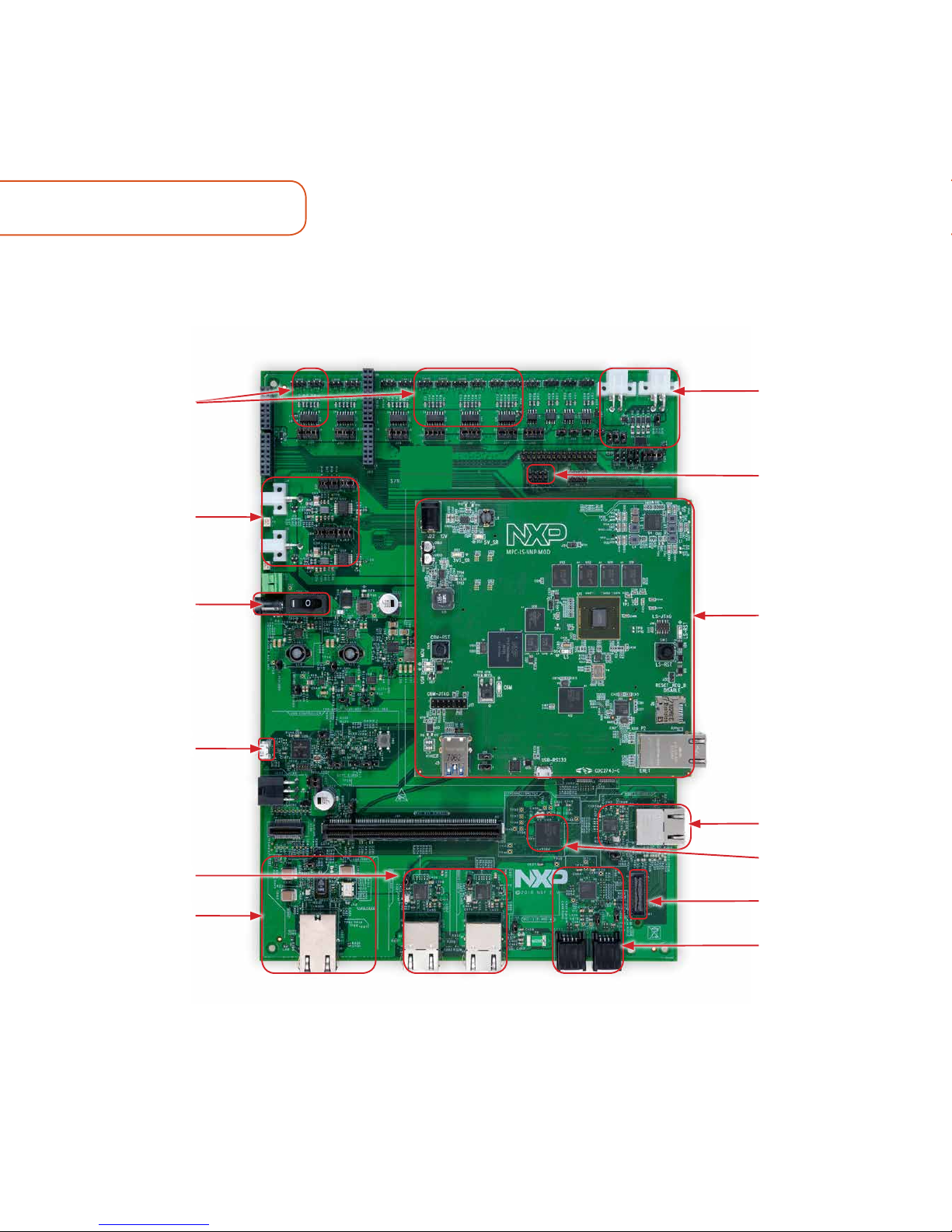
Figure 1: Front side of MPC-LS-VNP-EVB
LIN x4 TJA1024HG
SPI2CAN breakout
connector
MPC-LS Processor
Module
RGMII_C ENET
SJA1105Q
RGMII_B
MII x2
CAN 4x2 TJA1048T
FlexRay x2 TJA1081
Platform Board
Power Jack
MPC5748G Micro
USB Port
RGMII_A x2
SGMII
Page 3
3
MPC-LS PROCESSOR MODULEGET TO KNOW THE MPC-LS-VNP-EVB
www.nxp.com
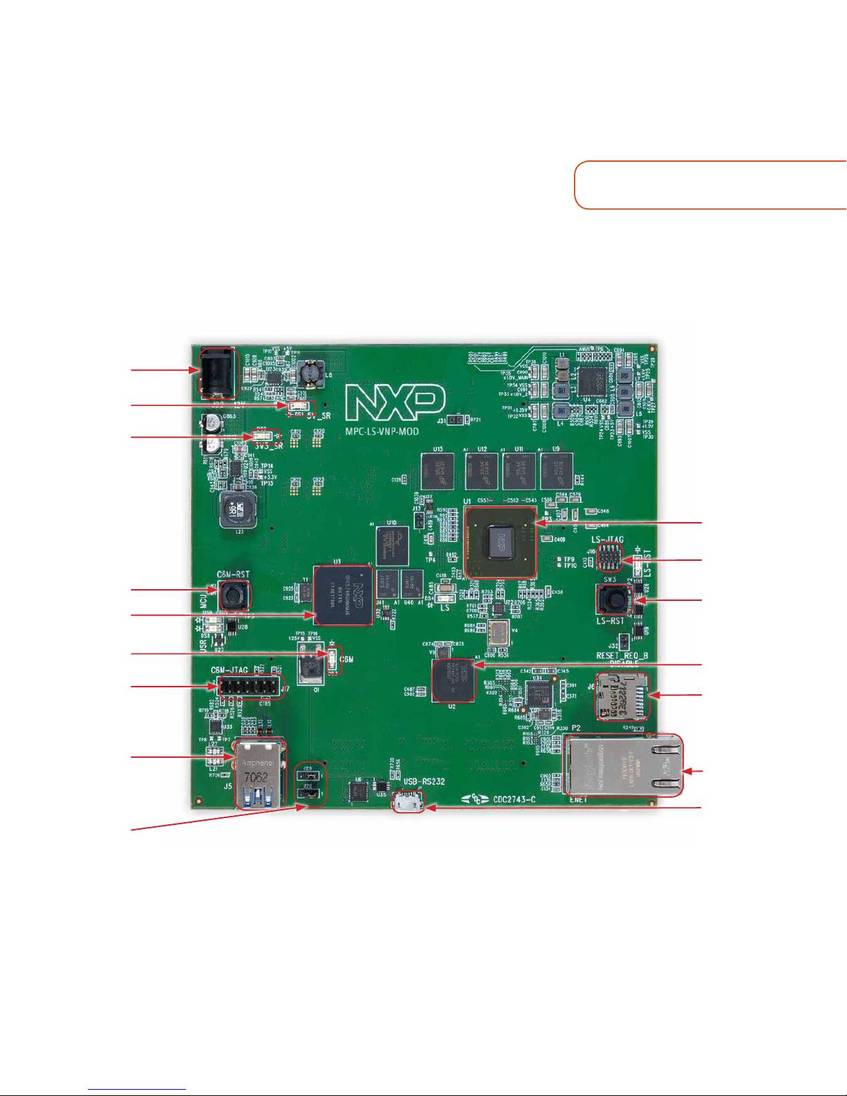
Figure 2: Front side of MPC-LS-VNP-MOD
LS1043A
LS1043A JTAG
LS1043A Reset
SJA1105S
Micro SD
Card Slot
Ethernet Port
Micro USB Port
Power Jack
DS1
DS2
MPC5748G
Reset
MPC5748G
DS3
MPC5748G JTAG
USB Port
J28 and J29
Page 4

4
MPC-LS-VNP-EVB
The NXP MPC-LS VNP EVB brings
an advanced automotive gateway
solution using NXP’s MPC5748G
gateway microcontroller and LS1043A
communications processor SoCs.
The combination of a real-time
microcontroller with microprocessor
application pro-cessing enables
new gateway use cases and serviceoriented gateways. The complete
MPC-LS VNP EVB solution consists
of two boards - a Processor Module
and a Platform Board with automotive
and Ethernet interfaces. The modular
design of the MPC-LS VNP EVB
enables the processor module to
be swapped out in the future to
support future gateway solutions
using the same platform board.
Page 5

5
www.nxp.com
MPC-LS-VNP-EVB FEATURES
Hardware
MPC5748G Automotive Microcontroller
• AEC-Q100, Grade 2
• ISO 26262 ASIL B Functional Safety
• Processors
– (2x) Power Architecture® e200z4 @ 160
MHz
– (1x) Power Architecture® e200z2 @ 80
MHz
• 6 MB embedded flash, 768 KB SRAM
• 8x CAN FD + 4 (Non FD) w/SPI expansion
• 2x AVB Ethernet (w/switch)
• 2x FlexRay, 4x LIN
• Embedded Hardware Security Module
(HSM)
– Supports SHE and EVITA standards
PMIC
• PF8200 PMIC
• Configurable and programmable outputs
to power the core processor, memory and
a wide range of peripherals
SJA1105S Automotive Ethernet Switches
• AEC-Q100, Grade 2
• 1024-entry MAC address learning table
• Hardware support for IEEE 802.1AS and
IEEE 802.1Qav for AVB networks
• SJA1105S: 4x MII/RMII RGMII, 1x SGMII
• SJA1105Q: 5x MII/RMII/RGMII
LS1043A Layerscape Microprocessor
• (4x) Arm® Cortex-A53 64-bit processors
– Up to 1.6 GHz
• Gigabit Ethernet Data Path Acceleration
• 10 Gbps Crypto Acceleration
• 2 GB DDR4 @ up to 1.6 GT/s
• 16 Gb NAND flash
• 1 Gb Serial NOR flash
• Micro SD card slot
• 2x 100Mbps, 5x 1Gbps, 1x 10Gbps
Ethernet, IEEE 1588
• 2x USB 3.0
Software
• MPC5748G: AUTOSAR, MCAL, Bare-metal
• LS1043A: Linux, fast path packet
forwarding
• Inter-Platform Communications
Framework (IPCF)
Page 6

6
STEP-BY-STEP INSTRUCTIONS
1
Connect the processor
module and platform board
For connecting, refer to the orientation of
boards shown in Figure 1.Refer to the MPCLS-VNP-EVB User Manual Section 5.1 for
board interconnectivity details.
2
Connect the
Power Supply
Connect power supply to the power jack of
the Platform Board and micro USB cable to
micro USB port on the MPC-LS Processor
Module. Make sure the DS1 and DS2 LEDs
for voltage levels 5V and 3.3V respectively
are glowing on the MPC-LS Processor
Module.
3
Install
FTDI Driver
Install the FTDI CDM v2.12.28 WHQL
driver as below:
Download the driver from FTDI Driver
Connect the micro USB cable from MPCLS Processor module to your Windows
machine.
Go to the Device Manager and rightclick the COM port detected and select
Update Driver Software.
Select Browse my computer for driver
software and select the FTDI driver that
has been downloaded.
Restart your machine.
Page 7

7
DEFAULT JUMPER SETTINGS
www.nxp.com
JUMPER OPTION SETTING DESCRIPTION
J28
UART to USB
Rx pin
1-2 LS1043A console
J29
UART to USB
Tx pin
1-2 LS1043A console
4
Setup Tera
Term Console
Open Tera Term on Windows PC.
Select the serial port to which the micro
USB of the MPC-LS Processor Module
is connected and click OK. Go to
Setup>Serial Port and select 115200 as
the baud rate.
5
Reset the
Board
Press the LS reset button on the MPC-LS
Processor Module. Do not press any key
while the counter goes down from 10 to
0. Enter “root” as login and press Enter.
6
Application
Startup
The getting started IPCF application is
auto executed on login.
Page 8

SUPPORT
Visit www.nxp.com/support for a list
of phone numbers within your region.
WARRANTY
Visit www.nxp.com/warranty for
complete warranty information.
www.nxp.com
NXP and the NXP logo are trademarks of NXP B.V. All other product or service names are the property of
their respective owners. © 2019 NXP B.V.
Document Number: MPCLSVNPEVBQSG REV 0
Get Started
Download installation
software and documentation at
www.nxp.com/MPC-LS-VNP-EVB.
 Loading...