

Page 1
MPCLSVNPEVBUM
MPC-LS Vehicle Network Processing Evaluation Board User
Manual
All information provided in this document is subject to legal disclaimers
Rev. 0 — Feb 2019
Contents
1 Introduction
The NXP MPC-LS VNP EVB brings an advanced automotive gateway solution
using NXP's MPC5748G gateway microcontroller and LS1043A
communications processor SoCs. The combination of a real-time
microcontroller with microprocessor application processing enables new
gateway use cases and service-oriented gateways. The complete MPC-LS
VNP EVB solution consists of two boards - a Processor Module and a Platform
Board with a wide array of automotive interfaces.
This document provides detailed reference information for the MPC-LS VNP
Evaluation Board (EVB) comprising a Processor Module and a Platform Board.
This includes detailed board configuration including connectors, jumpers, LED
notifications, board programming, and recovery instructions. The document
also includes usage of software tools and environment for building, flashing,
and debugging the board.
To get familiar with the system, the user needs to follow the below work flow:
1. Bring up the MPC-LS VNP EVB as described in the Quick Start Guide.
(Requires MPC-LS VNP EVB)
2. Install required software per section Software Requirements.
3. Build Linux and MPC5748G images as per section How to Build.
4. Flash images on LS1043A and MPC5748G per section How to flash the
board or perform board recovery on page 61. (Requires MPC-LS VNP
EVB)
1 Introduction..........................................1
2 Hardware requirements.......................1
3 Software requirements........................2
4 MPC-LS Processor Module details.... 3
5 MPC-LS Platform Board details..........6
6 Debugger connections...................... 11
7 Quick Start with MPC-LS VNP EVB.. 14
8 How to build the software for
LS1043A and MPC5748G................ 15
9 How to flash the board or perform
board recovery................................ 61
10 How to run the application..............93
A CodeWarrior CCS..............................96
B Running 64-bit guest on
VirtualBox........................................ 99
C Enable copy and paste from/to
VirtualBox...................................... 102
D Revision history.............................. 106
User's Guide
5. Run demo application as per section How to Run Application. (Requires MPC-LS VNP EVB)
NOTE
References to “DCM” in this manual are legacy references to the MPC-LS EVB Processor Module.
2 Hardware requirements
The table below lists the hardware required:
Table 1. Hardware requirements
Item Description
MPC-LS VNP EVB
12V, 5A power supply 12V adapter to power the board
Micro USB cable For console output from USB to UART port
MPC-LS processor board installed on platform board
Table continues on the next page...
Page 2

NXP Semiconductors
Software requirements
Table 1. Hardware requirements (continued)
Item Description
Ethernet cable Used to flash images to LS1043A via TFTP
CWH-CTP-BASE-HE CodeWarrior TAP kit for flashing / debugging LS1043A https://www.nxp.com/support/
developer-resources/software-development-tools/codewarrior-development-tools/run-controldevices/qoriq-ls-processor-probe-tips-for-codewarrior-tap:CWH-CTP-CTX10-YE?
tab=Buy_Parametric_Tab#/
CWH-CTP-CTX10-YE CodeWarrior Probe Tip to connect to the LS JTAG connector of MPC-LS processor module.
https://www.nxp.com/support/developer-resources/software-development-tools/codewarriordevelopment-tools/run-control-devices/qoriq-ls-processor-probe-tips-for-codewarriortap:CWH-CTP-CTX10-YE
JTAG debugger for PPC,
Debugger to flash and debug on MPC5748G
example: Lauterbach, PE
micro, GHS debugger
3 Software requirements
The table below lists the software required:
Table 2. Software requirements
Requirement Description Installation details Download Link
S32 Design Studio for
Power Architecture
2017.R1 - Windows/
Linux (REV 2017.R1)
Tera Term v4.101 A serial terminal emulator
CodeWarrior for Armv8 CodeWarrior IDE for
Design Studio for
®
MPC5748G build.
program for console.
Required for both Baremetal and AUTOSAR
package.
LS1043A debug via
CodeWarrior TAP. Required
for both Bare-metal and
AUTOSAR package.
Section 8.2 MPC5748G
Bare-metal Example
Build
Run the exe downloaded
from the download link.
Section 9.2.1 Using RAM
Boot
https://www.nxp.com/support/developer-
resources/run-time-software/s32-design-
studio-ide/s32-design-studio-ide-for-power-
architecture-based-mcus:S32DS-PA?
tab=Design_Tools_Tab
http://download.cnet.com/Tera-Term/
3001-2094_4-75766675.html
https://www.nxp.com/support/developerresources/software-development-tools/
codewarrior-development-tools/codewarriornetwork-applications/codewarriordevelopment-suites-for-networkedapplications:CW-DS-NETAPPS?
tab=Design_Tools_Tab
MPC-LS Vehicle Network Processing Evaluation Board User Manual, Rev. 0, Feb 2019
User's Guide
Table continues on the next page...
2 / 107
Page 3

NXP Semiconductors
MPC-LS Processor Module details
Table 2. Software requirements (continued)
Requirement Description Installation details Download Link
TRACE32 for PPC TRACE32 software for
debugging MPC5748G via
Lauterbach.
Required for both Baremetal and AUTOSAR
package.
Tftp64 v4.60 Tftp v4.60 server to transfer
files to LS1043A file system.
Required for both Baremetal and AUTOSAR
package.
Msys for Windows
v1.0.11
MSYS is a collection of GNU
utilities such as bash, make
used to build the application
on ARCCORE’s AUTOSAR.
Required for only
AUTOSAR package.
Mingw for Windows Free and open source
software development
environment to create
Microsoft® Windows
applications. Pre-requisite
for msys. Required for only
AUTOSAR package.
Click the Downloads
button on the left side and
navigate to the TRACE32
software.
Run the installer to install
the T32.
Run the exe file
downloaded from the
download link.
Refer section Msys and
Mingw Tool Installation for
more details.
Refer section Msys and
Mingw Tool Installation for
more details.
http://www.lauterbach.com/frames.html?
home.html
https://bitbucket.org/phjounin/tftpd64/
downloads/Tftpd64-4.60-setup.exe
http://downloads.sourceforge.net/mingw/
MSYS-1.0.11.exe
https://sourceforge.net/projects/mingw/files/
latest/download
VirtualBox for Windows
Host v 5.2.22
VirtualBox 5.2.22 for
Windows Host with Ubuntu
18 installed to build the
LSDK images on the same
machine. Required for both
Bare-metal and AUTOSAR
package.
FTDI driver for
Windows 10
CDM v2.12.28 WHQL driver
to access the serial console
of LS1043A in Windows 10.
Required for both Baremetal and AUTOSAR
package.
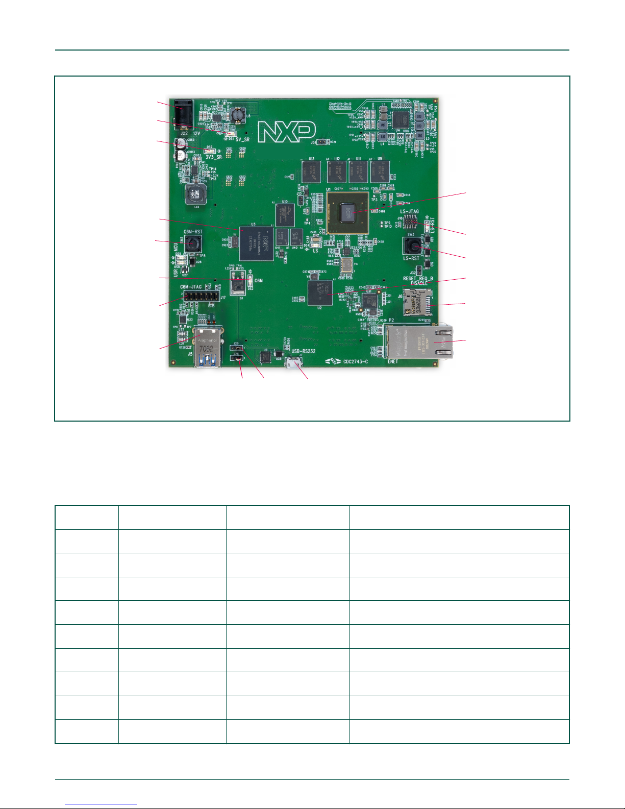
4 MPC-LS Processor Module details
The figure below displays the actual diagram of the MPC-LS Processor Module with components marked:
"Dual Chip Module" or "DCM" are legacy and refer to the MPC-LS Processor Module.
MPC-LS Vehicle Network Processing Evaluation Board User Manual, Rev. 0, Feb 2019
User's Guide
Refer section VirtualBox
on Windows Host.
Refer Quick Start Guide
for installing FTDI driver.
NOTE
https://www.virtualbox.org/wiki/Downloads
https://www.driverscloud.com/en/services/
DownloadDriver/71117-2/key
3 / 107
Page 4
LS1043A JTAG
LS1043A
Reset
LS1043A
SJA1105S
Micro SD
Card Slot
Ethernet Port
Micro USB PortJ29J28
USB Port
MPC5748G JTAG
DS3
MPC5748G
DS2
DS1
Power Jack
MPC5748G
Reset
MPC-LS-VNP-MOD
NXP Semiconductors
MPC-LS Processor Module details
Figure 1. MPC-LS Processor Module and its components
4.1 Connector and reset switches
The table below describes the MPC-LS Processor module connectors and reset switches:
Table 3. MPC-LS Processor module connectors and reset switches
Connector Description Connector Type/Function Typical connection
J22 12 V power jack DC power jack Connects to 12 V, 5 A power supply
SW5 MPC5748G reset
J17 MPC5748G JTAG 2x7 pin ARM JTAG header
J5 USB port 18-pin USB3.0 connector -open-
J7 Micro USB port Micro USB to UART Connects to the computer
P2 ENET port SGMII Ethernet port -open-
J6 MMC slot Micro SD slot -open-
J16 LS1043A JTAG 2x5 pin ARM JTAG header Connects to the CodeWarrior TAP
SW3 LS1043A reset
Resets MPC5748G Connects to the MPC5748G reset line
Resets LS1043A Connects to the LS1043A reset line
MPC-LS Vehicle Network Processing Evaluation Board User Manual, Rev. 0, Feb 2019
User's Guide
4 / 107
Page 5

NXP Semiconductors
MPC-LS Processor Module details
4.2 Jumpers
The table below shows the default jumper settings for the MPC-LS Processor Module:
Table 4. MPC-LS Processor Module jumper settings
Jumper Size Name/function Description
J13 1x2 pin LS Secure Boot Programming Enable Off: Normal Operation
On: Programming Mode
J28 1x3 pin UART to USB Rx pin 1-2: LS Serial port
2-3: MPC5748G Serial Port
J29 1x3 pin UART to USB Tx pin 1-2: LS Serial port
2-3: MPC5748G Serial Port
J31 1x2 pin USB_PWRFAULT Pull Select Off: No external pull
On: Pin pulled to GND (may be required by
USB software)
J32 1x2 pin Disable RESET_REQ_B from LS Off: RESET_REQ_B pin will trigger a reset
On: RESET_REQ_B pin is masked and will
not trigger reset
The default jumper setting on J28 and J29 is set to 1-2.
On the LS1043A side, the U-Boot is by default booted from the NOR flash.
LED indicators
4.3
The table below describes the MPC-LS Processor Module LEDs:
Table 5. MPC-LS Processor Module LEDs
LED
DS1 Red 5 V switching regulator output 5 V power present
DS2 Red 3.3 V switching regulator output 3.3 V power present
DS3 Blue MPC5748G general purpose
Color Name Description
General purpose port – PB[14]
LED
DS4 Red LS general purpose LED General purpose
DS7 Red LS1043A reset LS MPU in reset
MPC-LS Vehicle Network Processing Evaluation Board User Manual, Rev. 0, Feb 2019
User's Guide
Table continues on the next page...
5 / 107
Page 6

NXP Semiconductors
Table 5. MPC-LS Processor Module LEDs (continued)
MPC-LS Platform Board details
LED
DS8 Red MPC5748G target reset Reset on JTAG or reset button
DS9 Red MPC5748G MCU reset MPC5748G MCU in reset
Color Name Description
4.4 Resistor configurations
The resistor settings define the boot source of the LS1043A on MPC-LS Processor Module. The default boot source is kept to
NOR boot. The below resistor settings can be done for the respective boot source.
NOTE
Every resistor value is 4k7.
1. NOR Boot (default settings)
R85, R493 are unmounted.
R86, R88, R89, R90, R92, R492, R667 are mounted.
2. NAND Boot
R492, R493, R667 will be unmounted.
R85, R86, R88, R89, R90, R92 will be mounted.
3. SD Boot
R85 will be unmounted.
R86, R88, R89, R90, R92, R492, R493, R667 will be mounted.
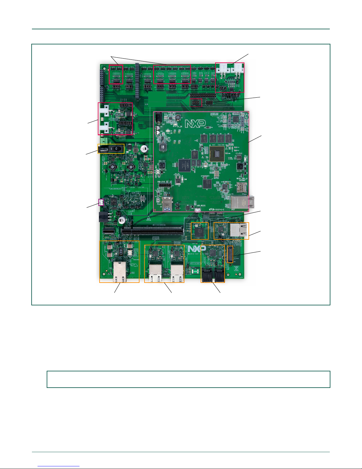
MPC-LS Platform Board details
5
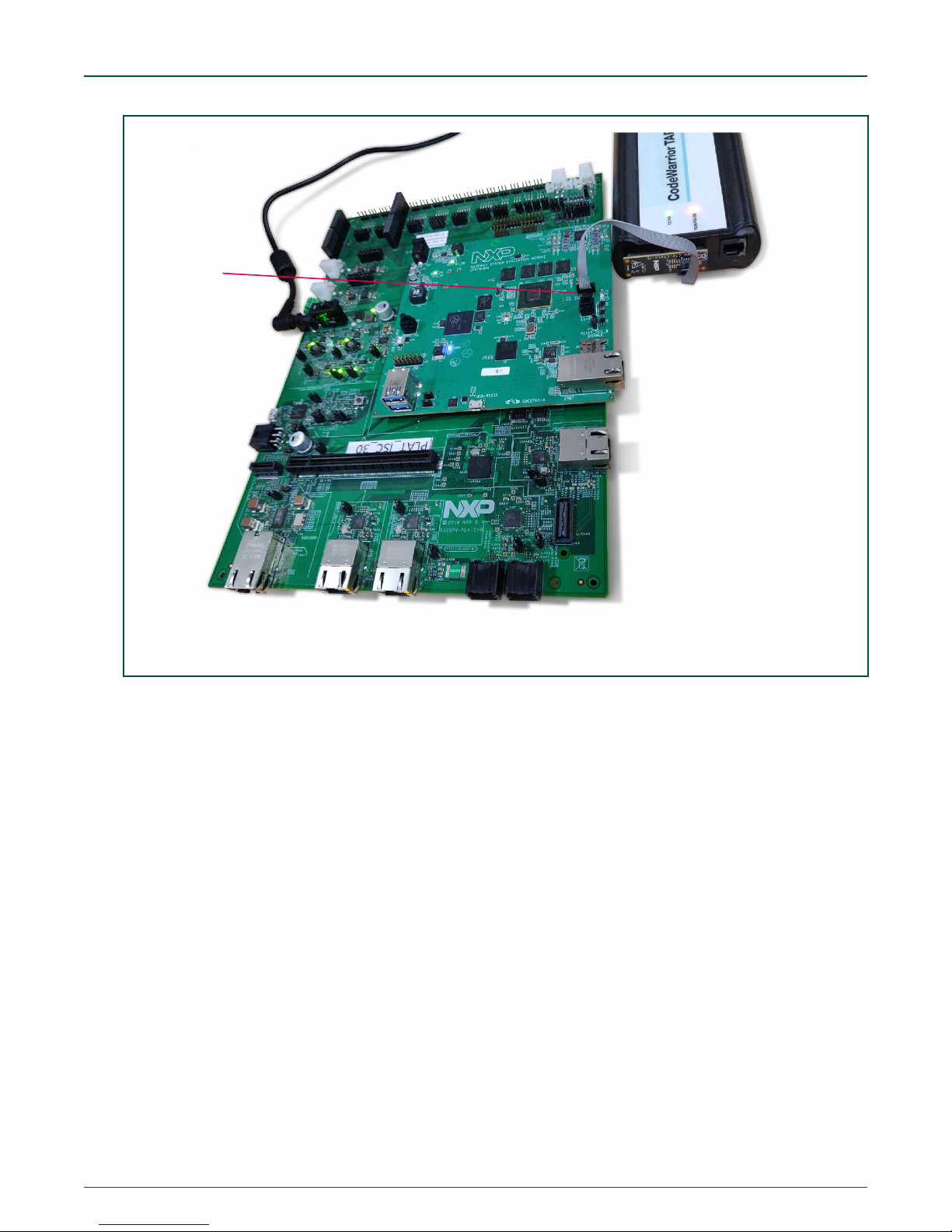
MPC-LS Platform board is equipped with connection to power supply. When used in Stacked mode (MPC-LS Processor Module
installed on the MPC-LS Platform Board), the power supply must be connected to the MPC-LS Platform power jack for all the
interfaces to be available. The MPC-LS Processor Module stacked over the MPC-LS Platform Board is shown in the figure below.
NOTE
MPC-LS Processor Module can be powered independently and used standalone.
Figure 2. MPC-LS Processor Module and MPC-LS Platform Board in Stacked mode
MPC-LS Vehicle Network Processing Evaluation Board User Manual, Rev. 0, Feb 2019
User's Guide
6 / 107
Page 7
MPC-LS Processor
Module
RGMII_C
RGMII_B
MII x2RGMII_A x2SGMII
MPC5748G
Platform Board
Power Jack
FlexRay x2
CAN 4x2
TJA1048T
LIN x4
SJA1105Q
micro USB port
SPI2CAN breakout
connector
TJA1081
TJA1024HG
MPC-LS-VNP-MOD
NXP Semiconductors
MPC-LS Platform Board details
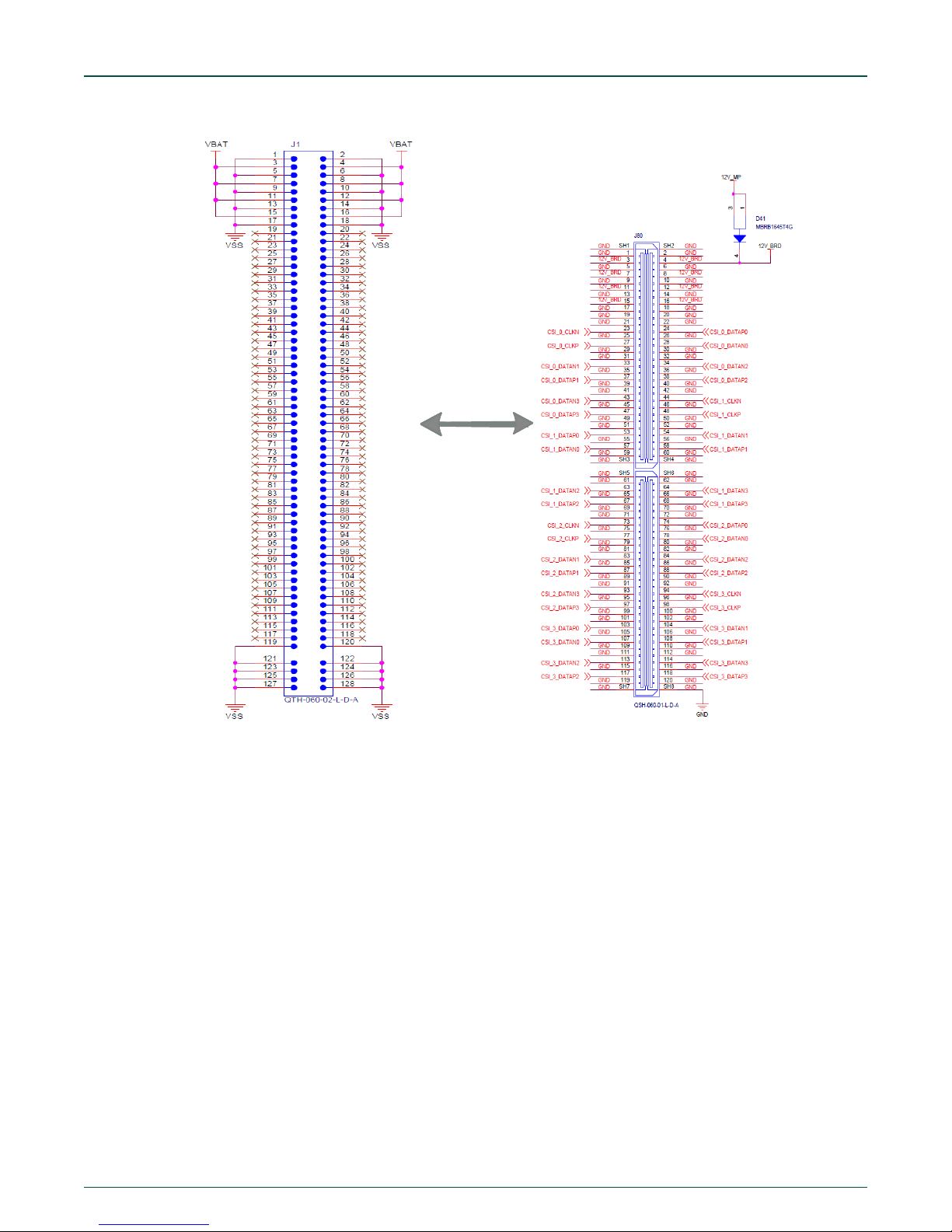
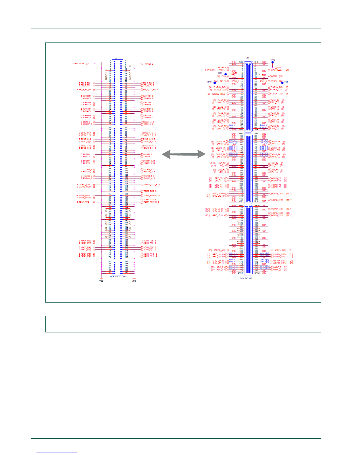
5.1 MPC-LS Processor Module connections to the MPC-LS Platform Board
The connections from MPC-LS Processor Module to the MPC-LS Platform Board can be referred from the schematics as shown
below:
MPC-LS Processor Module MPC-LS Platform Board
1. J1 <-> J80
Figure 4. J1<->J80 connection
MPC-LS Vehicle Network Processing Evaluation Board User Manual, Rev. 0, Feb 2019
User's Guide
7 / 107
Page 8
NXP Semiconductors
MPC-LS Platform Board details
2. J2 <-> J66
MPC-LS Vehicle Network Processing Evaluation Board User Manual, Rev. 0, Feb 2019
User's Guide
8 / 107
Page 9
NXP Semiconductors
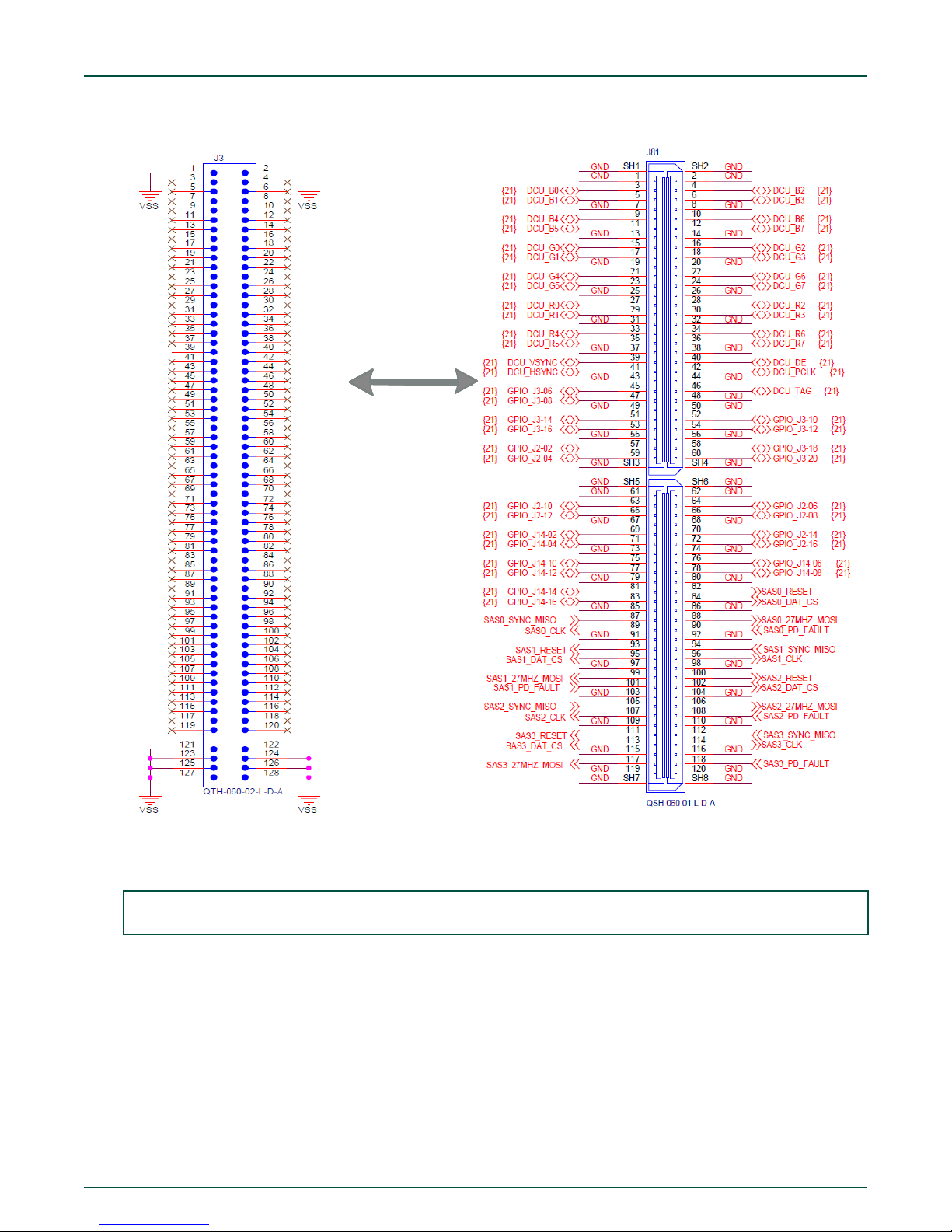
MPC-LS Platform Board details
Figure 5. J2 to J66
3. J3 <-> J81
Figure 6. J3 to J81
MPC-LS Vehicle Network Processing Evaluation Board User Manual, Rev. 0, Feb 2019
User's Guide
9 / 107
Page 10
NXP Semiconductors
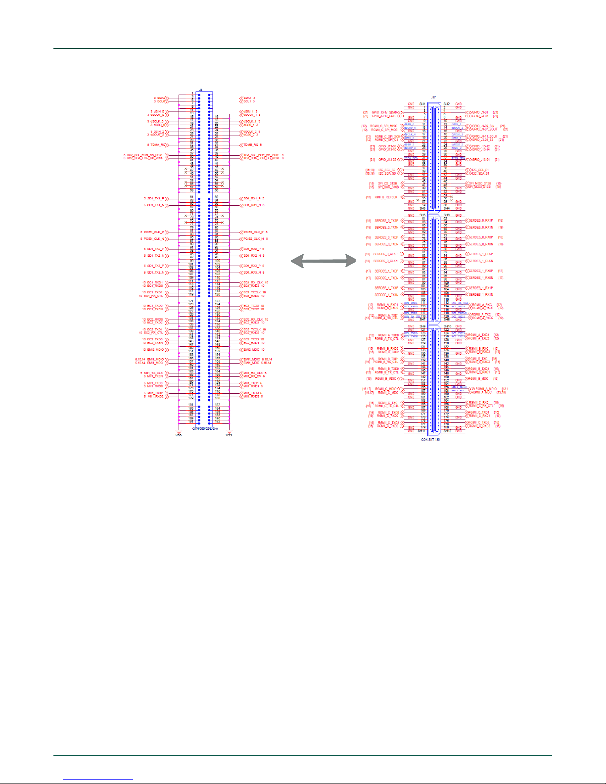
MPC-LS Platform Board details
4. J4 <-> J87
Figure 7. J4 to J87
MPC-LS Vehicle Network Processing Evaluation Board User Manual, Rev. 0, Feb 2019
User's Guide
10 / 107
Page 11
NXP Semiconductors
Debugger connections
6 Debugger connections
This section shows the hardware connection setup required to connect the debugger of LS1043A and MPC5748G with the MPCLS VNP EVB.
CodeWarrior TAP
6.1
The CodeWarrior TAP allows you to debug and control the LS1043A system on MPC-LS VNP EVB using the CodeWarrior IDE.
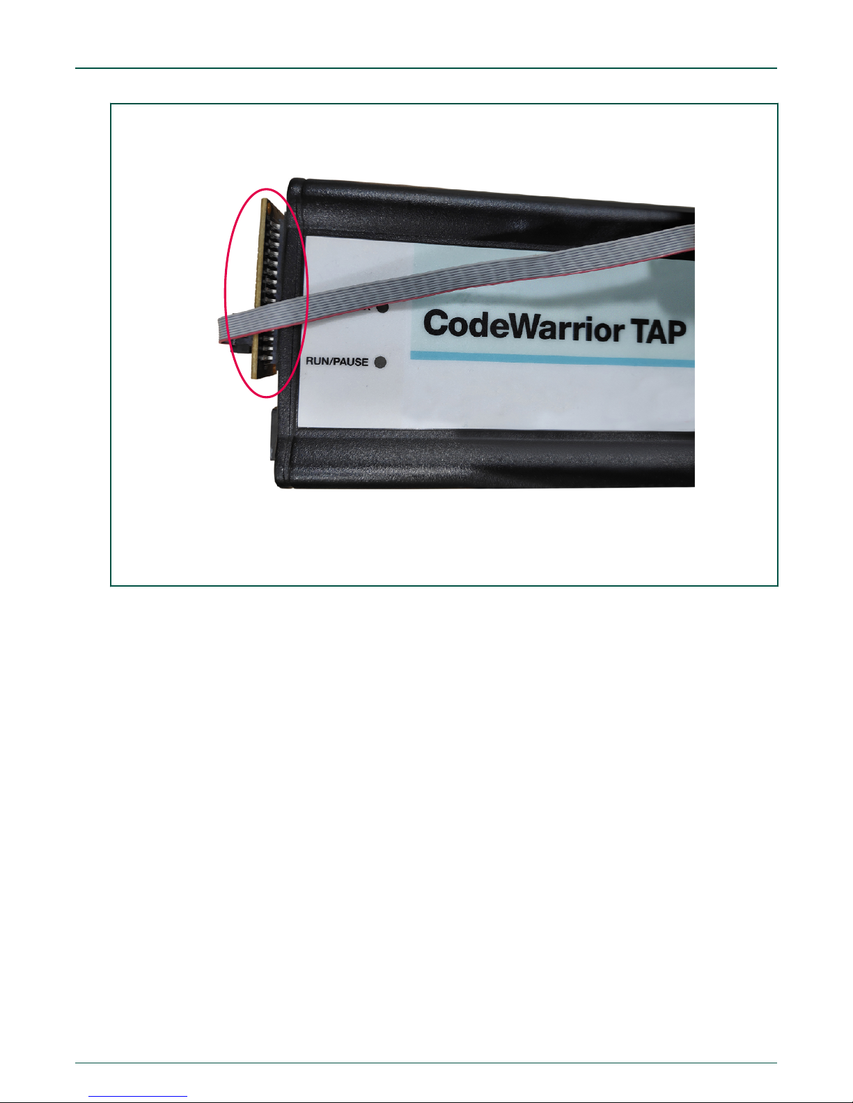
To attach the CodeWarrior TAP to MPC-LS VNP EVB, follow the steps below:
1. Attach the CodeWarrior TAP probe “CWH-CTP-CTX10-YE” to the CodeWarrior TAP as shown in the figure below:
MPC-LS Vehicle Network Processing Evaluation Board User Manual, Rev. 0, Feb 2019
User's Guide
11 / 107
Page 12
NXP Semiconductors
Debugger connections
Figure 8. Cable connections for the CodeWarrior TAP
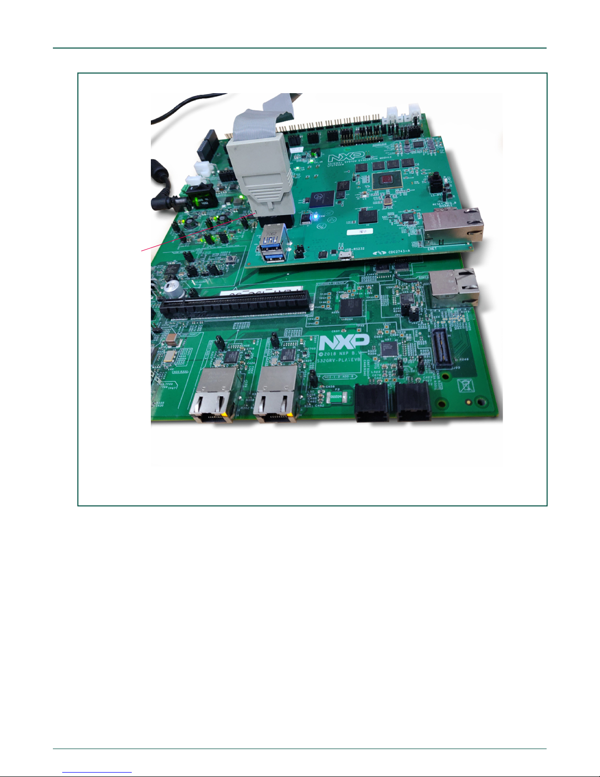
2. Connect the 10-wire cable to the JTAG headers on MPC-LS Processor Module. When aligned properly, the red stripe will
be on Pin 1 toward the inner side of the board.
MPC-LS Vehicle Network Processing Evaluation Board User Manual, Rev. 0, Feb 2019
User's Guide
12 / 107
Page 13
Pin 1
NXP Semiconductors
Debugger connections
Figure 9. Connecting the 10-wire cable to JTAG headers on MPC-LS Processor module
3. Connect the mini USB cable from CodeWarrior TAP to UART on PC.
The CodeWarrior TAP is now ready to be used.
Lauterbach
6.2
Lauterbach for PPC allows you to debug and control the MPC5748G system on the MPC-LS VNP EVB using T32mppc software.
To attach the Lauterbach to MPC-LS VNP EVB, follow the steps below:
1. Attach the standard 7.9 V Lauterbach supply to Lauterbach.
2. Connect the cable from Lauterbach to PC.
3. Connect the 14-wire cable to the JTAG header on MPC-LS VNP EVB with Pin 1 of the JTAG connector near the outside
of the board, the connector nipple should be on the side of the Ethernet connector as shown in the image below, as
shown below:
MPC-LS Vehicle Network Processing Evaluation Board User Manual, Rev. 0, Feb 2019
User's Guide
13 / 107
Page 14
Pin 1
NXP Semiconductors
Quick Start with MPC-LS VNP EVB
Figure 10. Connecting the 14-wire cable to JTAG header on MPC-LS VNP EVB with Pin 1
7 Quick Start with MPC-LS VNP EVB
There are two getting started packages released for MPC-LS VNP EVB:
1. Package 1:
MPC5748G – Bare-metal code
LS1043A - Open Source Linux Software Development Kit (LSDK), with MPC-LS VNP EVB patches
2. Package 2:
MPC5748G - ARCCORE’s AUTOSAR, with MPC-LS VNP EVB customizations and integrated IPCF
LS1043A - Open Source Linux Software Development Kit (LSDK), with MPC-LS VNP EVB patches and IPCF application
The user may refer to Quick Start Guide provided with each package.
MPC-LS Vehicle Network Processing Evaluation Board User Manual, Rev. 0, Feb 2019
User's Guide
14 / 107
Page 15
NXP Semiconductors
How to build the software for LS1043A and MPC5748G
NOTE
QSG is related only to the package which is pre-flashed on the board, which is AutoSAR + LSDK. The QSG for
Package 1 will be provided later on.
8 How to build the software for LS1043A and MPC5748G
The below section provides instructions to setup and build the software for LS1043A and MPC5748G.
• For LS1043A: Linux SDK.
• For MPC5748G: Bare-metal examples and AUTOSAR.
NOTE
A simplified Yocto build will be provided for MPC-LS-VNP EVB in near future.
8.1 LS1043A: Linux SDK Build
The build environment for the LS1043A can be either set up on Linux machine with Ubuntu 14/16/18 installed or on a VirtualBox
on a Windows host with Ubuntu 18. Once the build environment is set, all the proceeding steps to build are same irrespective of
whether it is a separate Linux machine or Linux on VirtualBox.
8.1.1 Linux Ubuntu machine
For a separate Linux Ubuntu machine, no external packages are required to be installed. The tool chain required to build the LSDK
images will be explained further in the scope of this document.
8.1.2 VirtualBox on Windows host
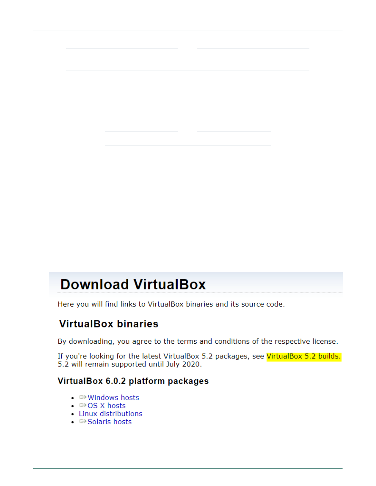
1. Open the webpage: https://www.virtualbox.org/wiki/Downloads.
2. Click on “VirtualBox 5.2 builds as highlighted in the snapshot below.
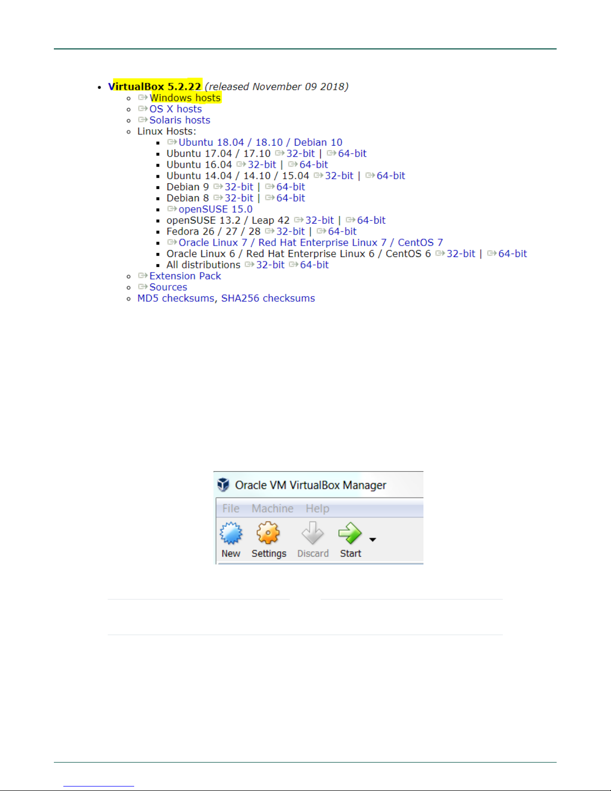
3. Download VirtualBox 5.2.22 for Windows Host as highlighted in the snapshot below.
MPC-LS Vehicle Network Processing Evaluation Board User Manual, Rev. 0, Feb 2019
User's Guide
15 / 107
Page 16
NXP Semiconductors
4. Run the installer.
How to build the software for LS1043A and MPC5748G
5. Download Ubuntu 18.04.
a. Go to https://www.ubuntu.com/desktop/developers .
b. Click on “Get Ubunto now” box.
c. Click on “Download” box for Ubunto 18.0.4.1 LTS.
d. The downloaded file is an ISO image. You will need this to mount it on the virtual drive. Steps to do that are
explained later in this section.
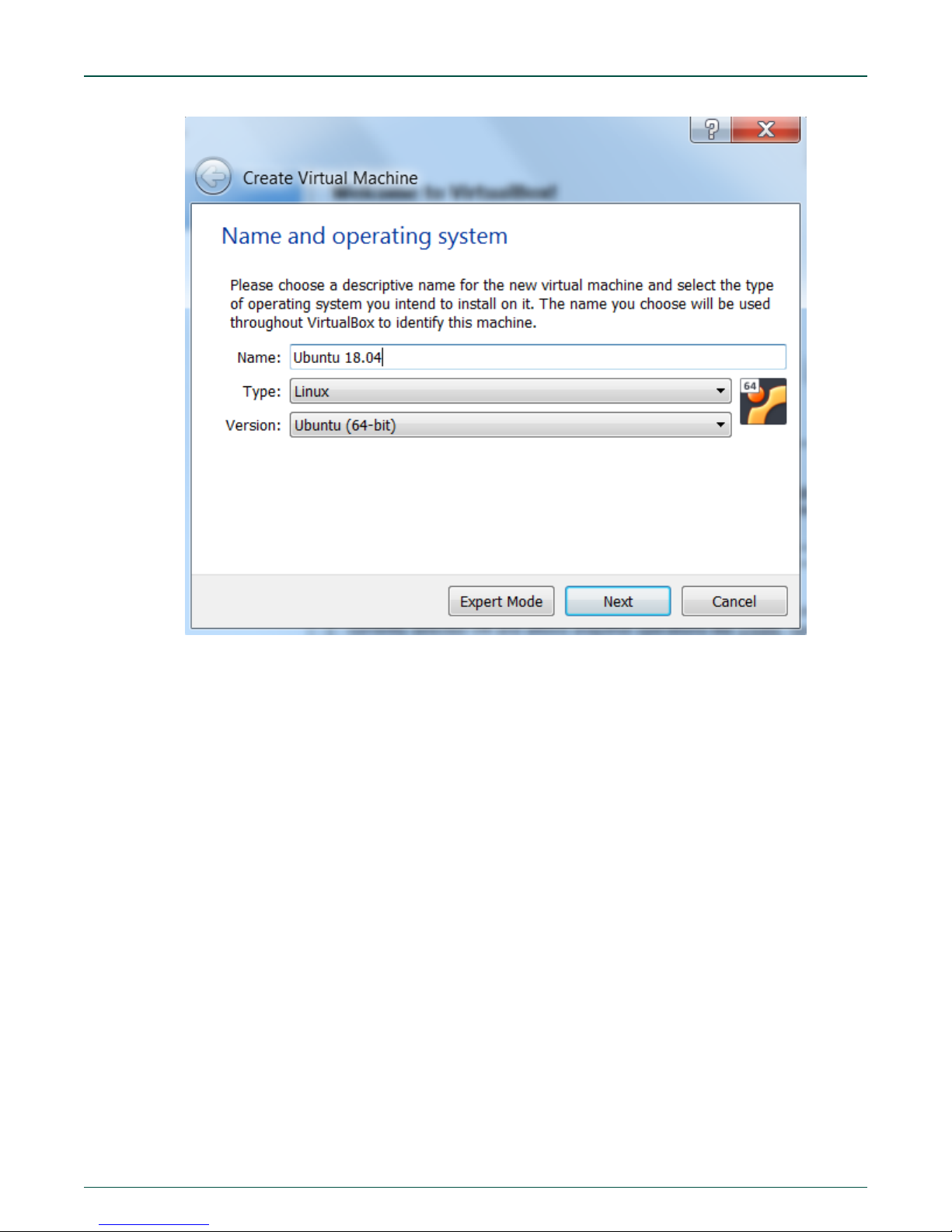
6. Open the VirtualBox Manager.
7. Click on New icon.
8. Provide Name: Ubuntu 18.04 , the type will be automatically selected to Linux, select version as Ubuntu (64-bit) only.
NOTE
If you see option only to run the 32-bit Ubuntu, follow section Run 64 bit guest on VirtualBox of Annexure section
B.
MPC-LS Vehicle Network Processing Evaluation Board User Manual, Rev. 0, Feb 2019
User's Guide
16 / 107
Page 17
NXP Semiconductors
How to build the software for LS1043A and MPC5748G
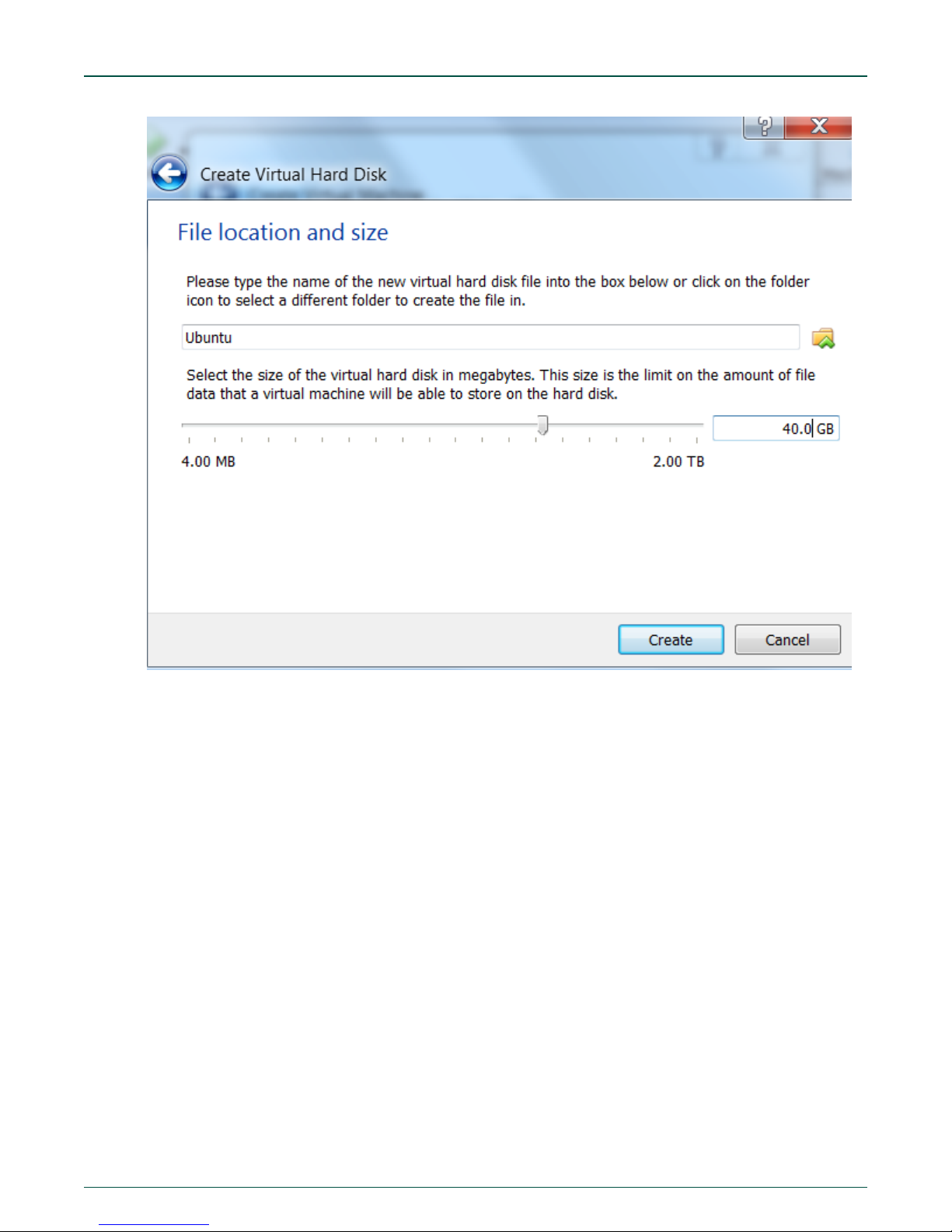
9. Allocate RAM of at least 2048 MB. Recommended RAM is 4096 MB if your PC machine has a RAM more than 8 MB.
10. Select create a virtual hard disk now.
11. Select hard disk file type as VDI (VirtualBox Disk Image).
12. Select storage on physical hard disk to be Fixed size.
13. Select virtual hard disk size to 40 GB as shown in the snapshot below.
MPC-LS Vehicle Network Processing Evaluation Board User Manual, Rev. 0, Feb 2019
User's Guide
17 / 107
Page 18
NXP Semiconductors
How to build the software for LS1043A and MPC5748G
14. The Install Manager will confirm if you need to create the virtual hard disk. Select Create.
15. Select the default directory for the file location.
16. The virtual hard disk will be created.
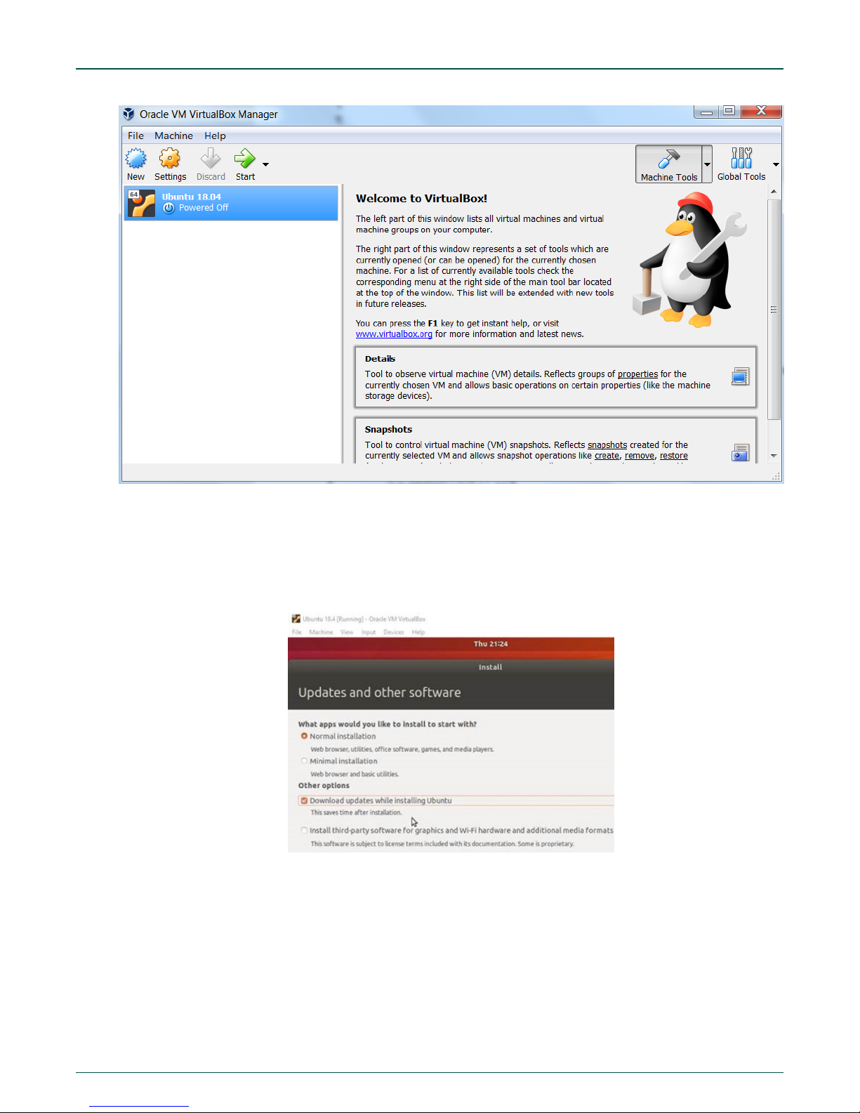
17. If not selected as shown below, select the Ubuntu 18.04 disk and click on Start.
MPC-LS Vehicle Network Processing Evaluation Board User Manual, Rev. 0, Feb 2019
User's Guide
18 / 107
Page 19
NXP Semiconductors
How to build the software for LS1043A and MPC5748G
18. The Manager will ask to select the startup disk. Provide the Ubuntu 18.04 iso file ‘ubuntu-18.04.1-desktop-amd64.iso’
here that is downloaded in step 5. Click on Start once loaded.
19. The install wizard for Ubuntu will come up. Select the language and click on Install Ubuntu.
20. Select Keyboard layout as per your convenience. Selected “English(UK)” in our case.
21. Select Normal Installation option and tick the Download updates while installing Ubuntu button.
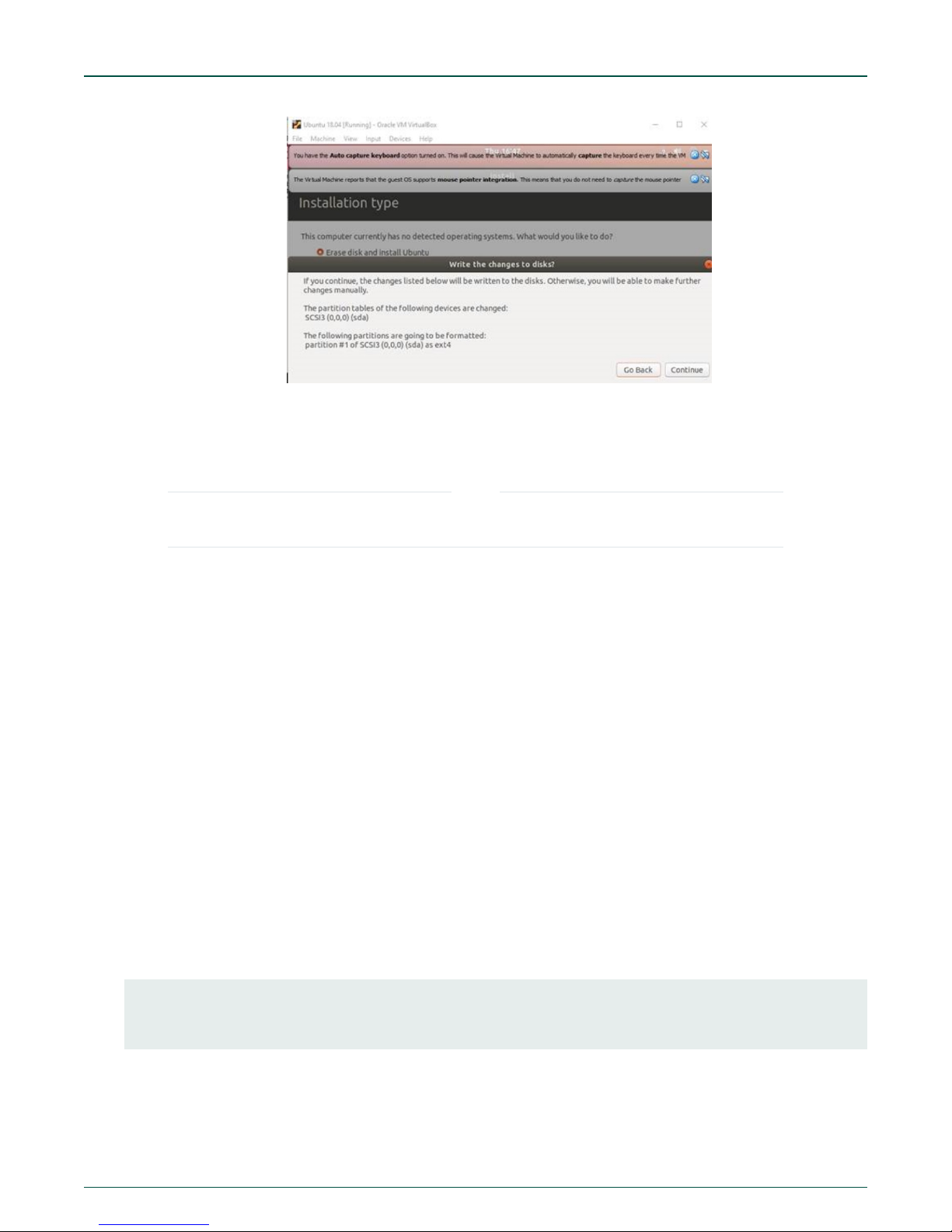
22. Select Erase disk and install Ubuntu, click on Install Now
23. Click Continue on the pop-up window.
MPC-LS Vehicle Network Processing Evaluation Board User Manual, Rev. 0, Feb 2019
User's Guide
19 / 107
Page 20
NXP Semiconductors
24. Provide your location and your login credentials.
25. Ubuntu will be installed.
26. If you get the message “Remove Media”, then just hit enter.
All the further instructions and steps mentioned for Linux are common and applicable to both Linux Ubuntu machine
as well as Ubuntu on VirtualBox.
NOTE
How to build the software for LS1043A and MPC5748G
8.1.3 Linux LSDK17.12 setup and build
Open Source Linux Software Development Kit (LSDK).
8.1.3.1 Source path
1. The LSDK source and binaries can be found at “https://lsdk.github.io/”. For details on downloading them, follow the below
steps.
2. In total 5 images will be flashed on LS1043A. Out of which the binaries of ‘ppa.itb’ and ‘fsl_fman’ will be readily available
on git hub and the source code for ‘rcw’, ‘U-Boot’ and ‘Linux’ will be downloaded/cloned from git hub and built locally.
Here is a brief description of all these images used:
a. RCW: Reset configuration word.
b. U-Boot: Universal Boot Loader.
c. PPA: Primary Protected Application.
d. Fman: Frame manager hardware accelerator.
e. Linux: Linux image.
3. Create DCM_git directory at /home/<user> to store the LSDK17.12 source code.
4. For rcw source, go inside the DCM_git directory and pass the below commands. Copy and paste may not work by
default in the virtual box. If this is the case, follow section Enable copy and paste from/to VirtualBox of Annexure.
>> git clone https://source.codeaurora.org/external/qoriq/qoriq-components/rcw
>> cd rcw
>> git checkout -b integration origin/github.com.qoriq-os/integration
The source will be automatically stored to a directory rcw.
MPC-LS Vehicle Network Processing Evaluation Board User Manual, Rev. 0, Feb 2019
User's Guide
20 / 107
Page 21
NXP Semiconductors
How to build the software for LS1043A and MPC5748G
Note: Use the command sudo apt install git if git is not already installed and git config --global user.email
“you@email.com”” to set your account’s default identity.
>>cd ..
5. For the U-Boot and linux images, follow the below steps in DCM_git directory:
U-Boot:
“git clone https://github.com/qoriq-open-source/u-boot”
Linux:
“git clone https://github.com/qoriq-open-source/linux”
DCM_git directory will have the below three directories:
• rcw
• u-boot
• linux
6. Change the directory to u-boot by using cd and enter the command git checkout -b LSDK-17.12 LSDK-17.12 to
make sure the tag used for LSDK is 17.12.
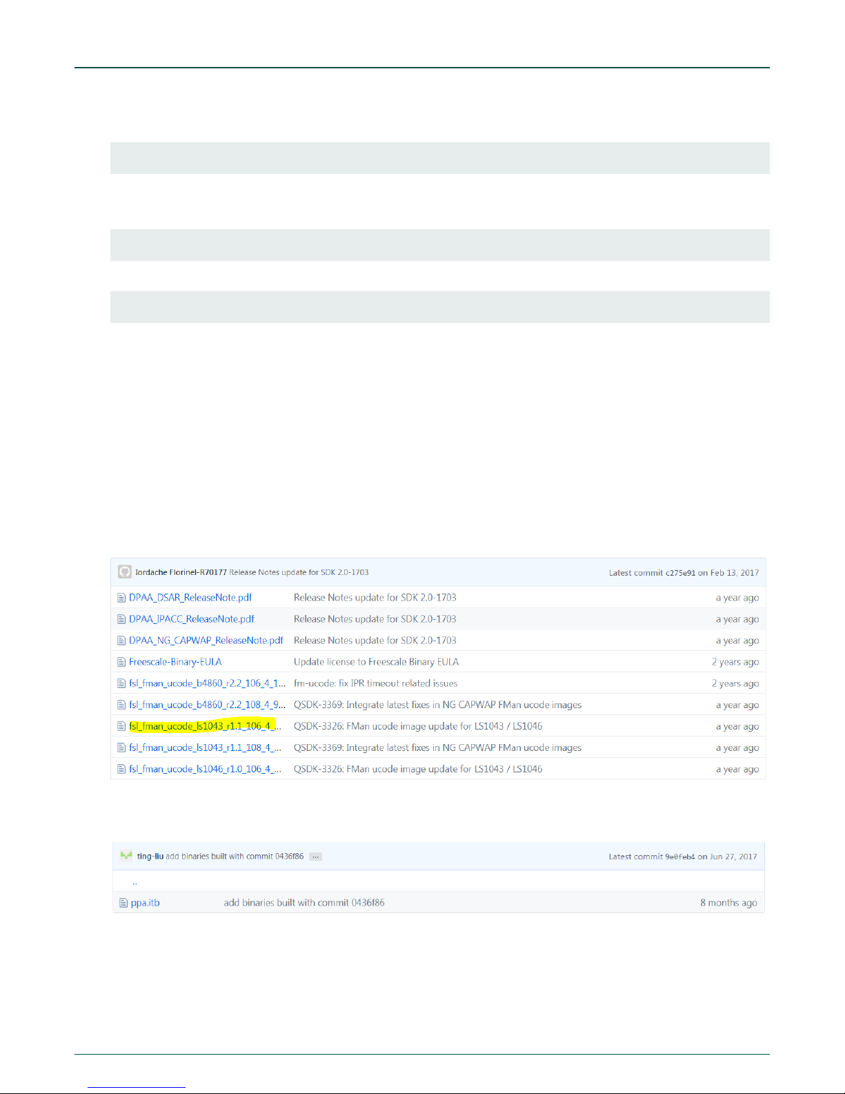
7. For fsl_fman and ppa.itb, binaries are provided on the webpage.
8. Fsl_fman: Go to https://github.com/NXP/qoriq-fm-ucode
In the directory, download fsl_fman_ucode_ls1043_r1.1_106_4_18.bin. This binary will be later used in the "how to flash
section.
Ppa.itb: Go to https://github.com/NXP/qoriq-ppa-binary/blob/integration/soc-ls1043/ppa.itb
Select soc-ls1043.
Download the .itb file.
MPC-LS Vehicle Network Processing Evaluation Board User Manual, Rev. 0, Feb 2019
User's Guide
21 / 107
Page 22
NXP Semiconductors
How to build the software for LS1043A and MPC5748G
8.1.3.2 Ubuntu build tool chain
On your Ubuntu machine, run the following set of commands to download the linaro tool chain and set the cross compiler before
building the source code.
1. Download the open source gcc linaro tool chain (gcc-linaro-6.3.1-2017.05-x86_64_aarch64-linux-gnu) from the
URL: https://releases.linaro.org/components/toolchain/binaries/6.3-2017.05/aarch64-linux-gnu/ and save it inside the
DCM_git directory.
2. Untar the file using tar -xf gcc-linaro-6.3.1-2017.05-x86_64_aarch64-linux-gnu.tar.xz.
3. Then, use the following commands:
>>sudo apt install crossbuild-essential-arm64 gcc-aarch64-linux-gnu
>>export CROSS_COMPILE=aarch64-linux-gnu>>export ARCH=arm64
>>sudo apt install device-tree-compiler
>>export PATH=$PATH:/home/<user>/DCM_git/gcc-linaro-6.3.1-2017.05-x86_64_aarch64-linux-gnu/bin
8.1.3.3 Apply patches
Create three folders in DCM_git for patches named:
• dcm-linux_patches
• dcm-rcw_patches
• dcm-uboot_patches
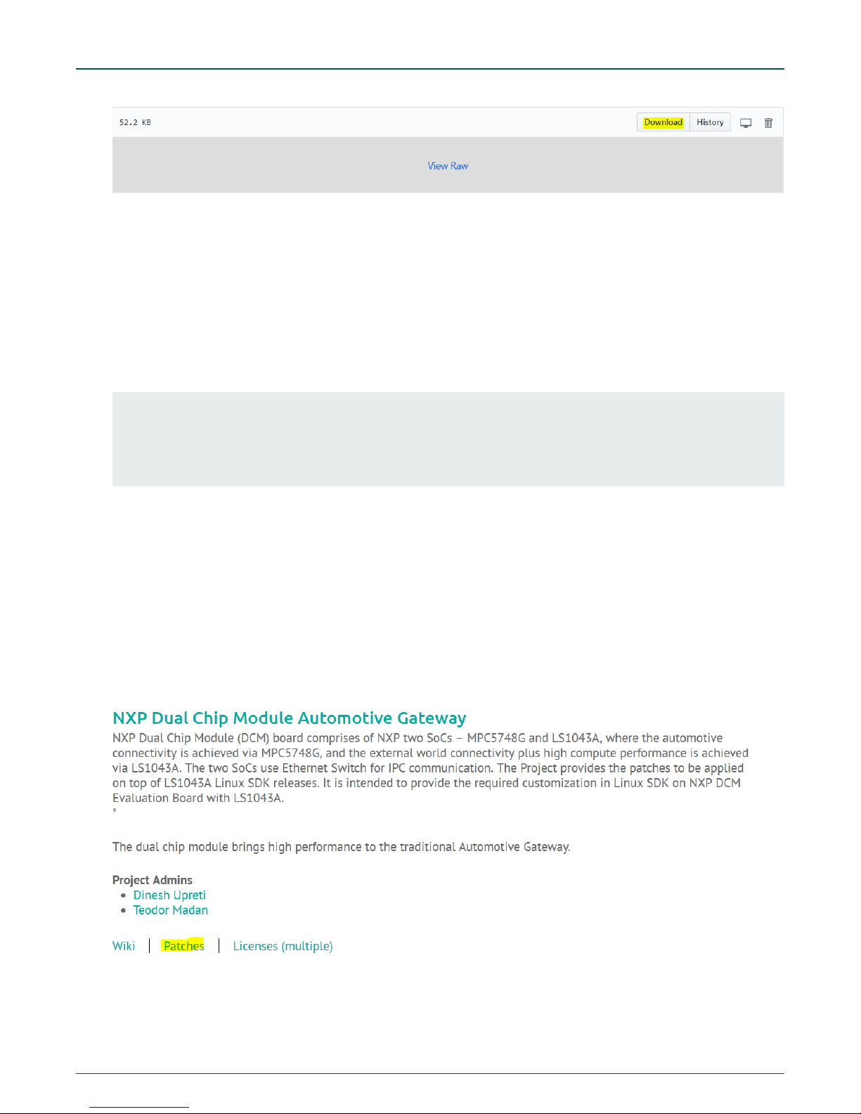
Download the patches for RCW, U-Boot, and Linux in ‘dcm-rcw_patches’, ‘dcm-uboot_patches’, and ‘dcm-linux_patches’
directories respectively from the URL: https://www.codeaurora.org/project/nxp-dual-chip-module-automotive-gateway.
Click on patches:
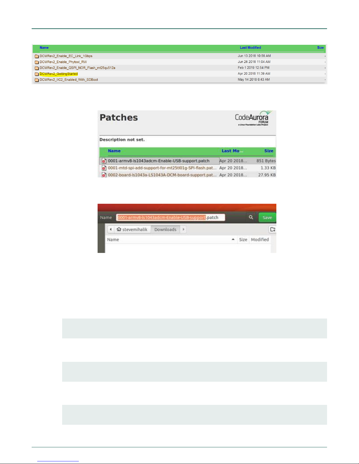
Select DCMRev2_GettingStarted and download the three packages from there.
MPC-LS Vehicle Network Processing Evaluation Board User Manual, Rev. 0, Feb 2019
User's Guide
22 / 107
Page 23
NXP Semiconductors
The patches need to be downloaded one at a time. For example:
1. Click on the first patch to be downloaded:
2. Patch text file opens. Right-click anywhere in file and select Save Page As….
How to build the software for LS1043A and MPC5748G
3. The default name appears. Click on Save.
4. Repeat for all patches.
5. Change the name of the following patch:
0001-armv8-ls1043adcm-Enable-USB-support.patch to
0014-armv8-ls1043adcm-Enable-USB-support.patch.
6. Apply patches as instructed below:
a. Go to U-Boot directory
>cd u-boot>>
sudo git am ../dcm-uboot_patches/*
The patch will be applied to U-Boot.
b. Go back to DCM_git directory.
>>cd linux
>>sudo git am ../dcm-linux_patches/*
The patch will be applied to Linux.
c. Go back to DCM_git directory.
>>cd rcw
>>sudo git am ../dcm-rcw_patches/*
MPC-LS Vehicle Network Processing Evaluation Board User Manual, Rev. 0, Feb 2019
User's Guide
23 / 107
Page 24
NXP Semiconductors
How to build the software for LS1043A and MPC5748G
The patch will be applied to rcw directory.
NOTE
If there are errors while applying the patches, the user can run the command “sudo git am -abort” in the u-boot,
linux, and rcw directories. This ensures that there is no patch error initially. If still the error persists, the user can
clone the sources again and try applying patches again.
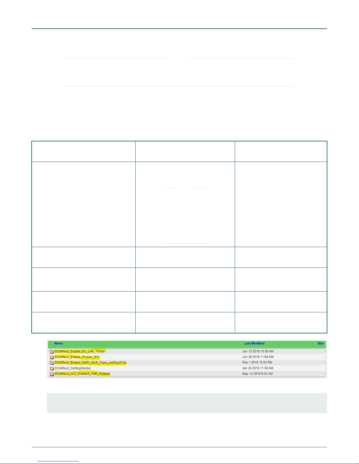
7. Create two new folders in DCM_git folder:
• dcm-linux_patches_addons
• dcm-uboot_patches_addons
8. From the CAF link, download patches from remaining folders into the two new folders as shown in the table below.>
Table 6. Download patches
Source folder File copied to dcm-
linux_patches_addons folder
DCMRev2_Enable_EC_Link_1Gbps /dcmlinux_patches
DCMRev2_Enable_EC_Link_1Gbps /dcm-
0001-fman_memac_adjust_link-if-RGMIIensure-RG-and-IFMODE.patch
NOTE
Do not download
0002memac_init_physetadjust_linkcallback-evenfor-fix.patch
0001-Enable-RGMII.PATCH
File copied to dcmuboot_patches_addons folder
uboot_patches
DCMRev2_Enable_Phytool_RW 0001-sdk_dpaa-dpa_ioctl-allow-passing-
of-SIOCSMIIREG-and-.patch
DCMRev2_IIC2_Enabled_With_SDBoot 0001-board-ls1043adcm-Enable-IIC2-
controller-during-SD-bo.patch
DCMRev2_
Enable_QSPI_NOR_Flash_mt25qu512a
9. Follow the below steps to add these patches:
>cd u-boot
sudo git am ../dcm-uboot_patches_addons/*
MPC-LS Vehicle Network Processing Evaluation Board User Manual, Rev. 0, Feb 2019
User's Guide
0002-dcm-Add-support-for-new-flashmt25qu512.patch
24 / 107
Page 25

NXP Semiconductors
10. For adding the linux patch, use:
>cd ../linux
>sudo git am ../dcm-linux_patches_addons/*
8.1.3.4 Build RCW
Use the steps described in this section to build RCW.
1. Run the below commands to build the image for rcw:
export CROSS_COMPILE=aarch64-linux-gnuexport ARCH=arm6
export PATH=$PATH:/home/<user>/DCM_git/gcc-linaro-6.3.1-2017.05-x86_64_aarch64-linux-gnu/bin
cd ../rcw/ls1043ardb
make
How to build the software for LS1043A and MPC5748G
2. If the user gets the “Python2 command not found” error, the user can run the below commands to install python:
>>sudo apt install python -minimal
If the user gets “tclsh command not found” error, the user can run the below commands to install tcl:
>>sudo apt install tcl
3. Now, run the command:
tclsh ../tools/byte_swap.tcl RR_SPPP_3560/rcw_1600_qspiboot.bin RR_SPPP_3560/
rcw_1600_qspiboot_swapped.bin 8
NOTE
The command mentioned above is a single command.
After successful build, the bin “rcw_1600_qspiboot_swapped.bin” will be successfully built at “../rcw/ls1043ardb/
RR_SPPP_3560”.
MPC-LS Vehicle Network Processing Evaluation Board User Manual, Rev. 0, Feb 2019
User's Guide
25 / 107
Page 26
NXP Semiconductors
How to build the software for LS1043A and MPC5748G
8.1.3.5 Building U-Boot
Follow these steps for building U-Boot specifically for a defined boot source.
1. Before building, create a directory u-boot_binary inside /DCM_git/. Create four subdirectories inside it:
• ddr
• qspi
• nand
• sd
2. Go to the DCM_git directory and run the following commands:
cd u-boot
export ARCH=arm64
export CROSS_COMPILE=aarch64-linux-gnu-
NOTE
Be sure to include the dash at the end of command, after …gnu-.
3. Now, run the command:
export PATH=$PATH:/home/<user>/DCM_git/gcc-linaro-6.3.1-2017.05-x86_64_aarch64-linux-gnu/bin
After running the above commands, use the commands in the following section to build specific U-Boot.
8.1.3.5.1 DDR boot
1. make distclean && make ls1043adcm_sdcard_defconfig && make -j3
2. In the same directory, the file “u-boot-dtb.bin” is the U-Boot created for dram.
MPC-LS Vehicle Network Processing Evaluation Board User Manual, Rev. 0, Feb 2019
User's Guide
26 / 107
Page 27
NXP Semiconductors
How to build the software for LS1043A and MPC5748G
3. Copy the binary to /DCM_git/u-boot_binary/ddr/ and rename it to “u-boot-dtb_ramboot.bin”.
NOTE
The U-Boot binary in the /DCM_git/u-boot directory will be replaced by the binary of the latest U-Boot build i.e after
the instructions to build QSPI NOR U-Boot are passed, the U-Boot binary for DDR is overwritten.
8.1.3.5.2 QSPI NOR boot
1. make distclean && make ls1043adcm_defconfig && make -j3
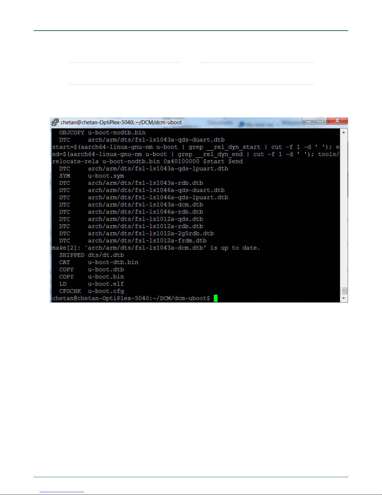
2. In the same directory, the file “u-boot-dtb.bin” is the U-Boot created for QSPI.
3. Copy the binary to /DCM_git/u-boot_binary and rename it to “u-boot-dtb_qspi.bin”.
8.1.3.5.3 NAND boot
1. make distclean && make ls1043adcm_nand_defconfig && make -j3
MPC-LS Vehicle Network Processing Evaluation Board User Manual, Rev. 0, Feb 2019
User's Guide
27 / 107
Page 28
NXP Semiconductors
How to build the software for LS1043A and MPC5748G
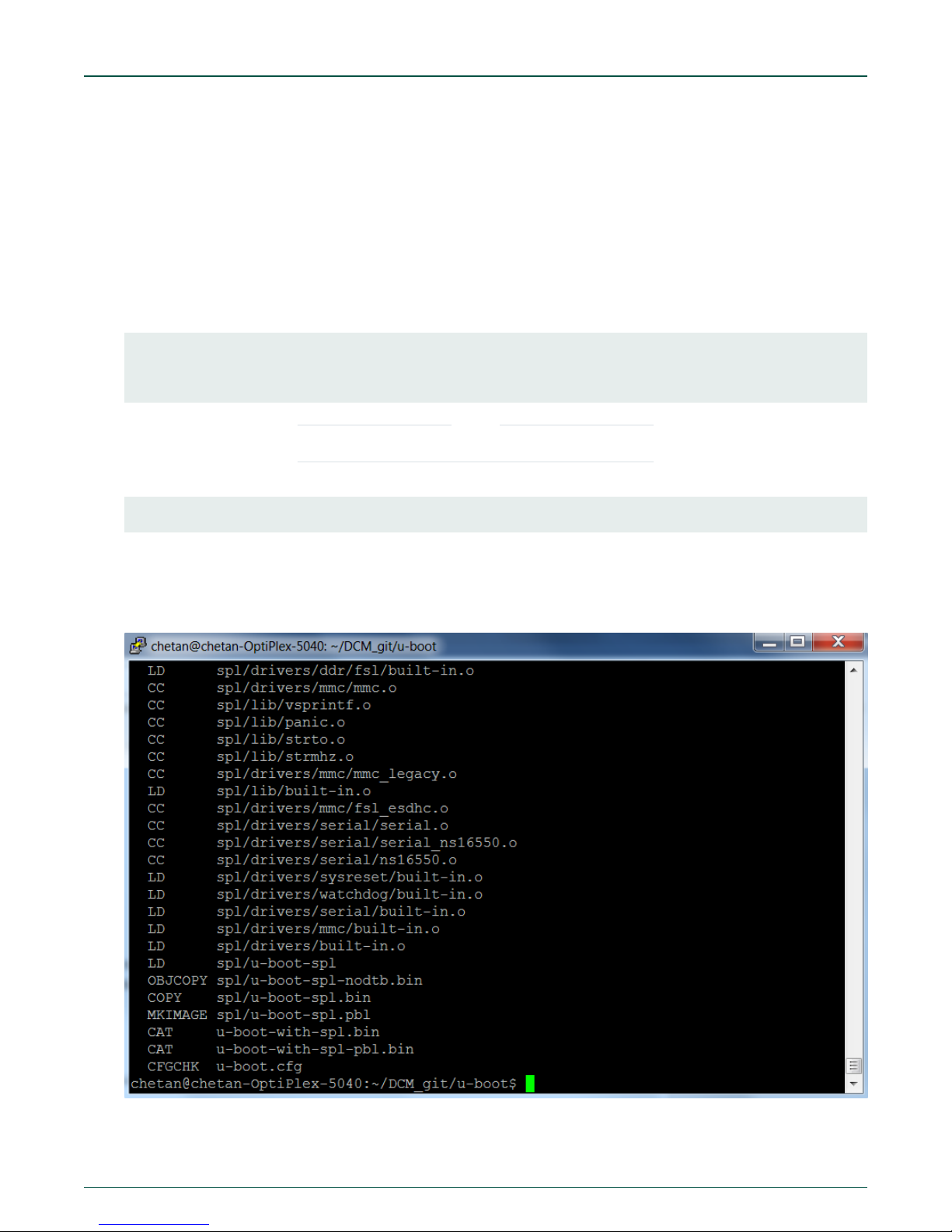
2. In the same directory, the file “u-boot-with-spl-pbl.bin” is the U-Boot created for NAND.
3. Copy the binary to /DCM_git/u-boot_binary/nand and rename it to “u-boot-with-spl-pbl-nand.bin”.
8.1.3.5.4 SD boot
1. make distclean && make ls1043adcm_sdcard_defconfig && make -j3
MPC-LS Vehicle Network Processing Evaluation Board User Manual, Rev. 0, Feb 2019
User's Guide
28 / 107
Page 29
NXP Semiconductors
How to build the software for LS1043A and MPC5748G
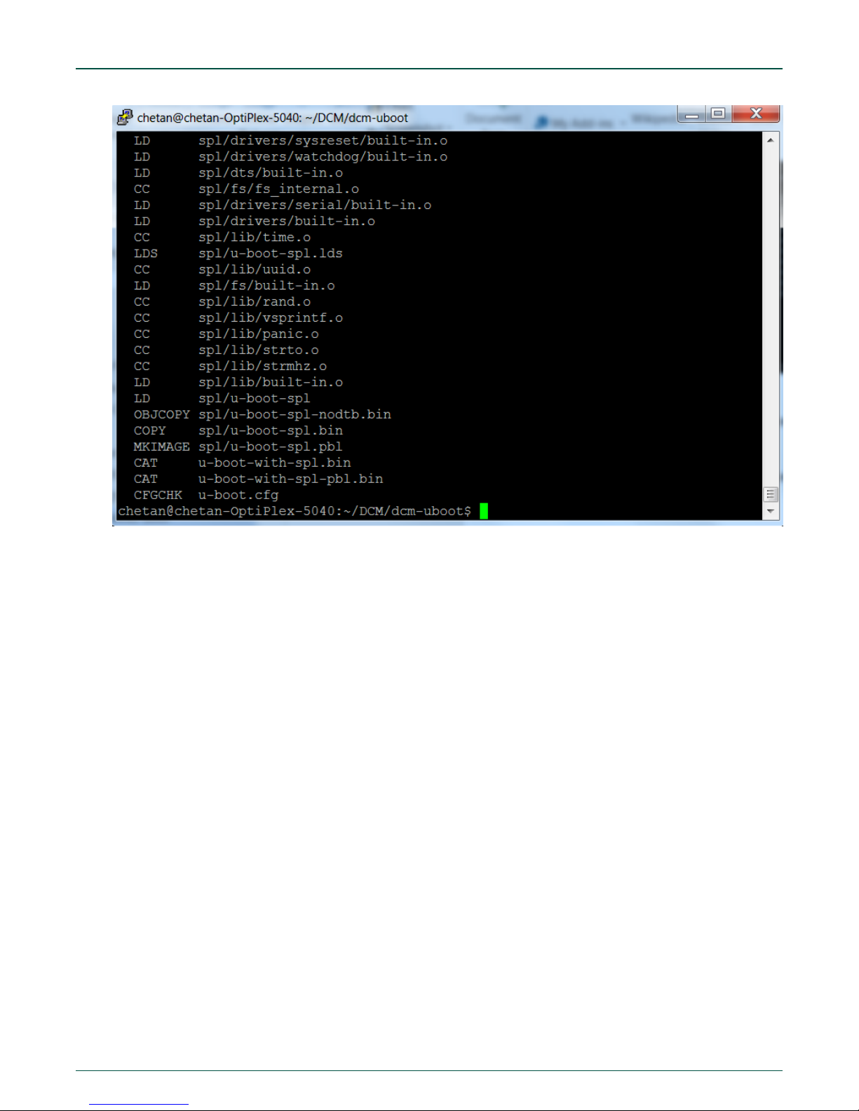
2. In the same directory, the file “u-boot-with-spl-pbl.bin” is the U-Boot created for sd memory.
3. Copy the binary /DCM_git/u-boot_binary/sd and rename it to “u-boot-with-spl-pbl_sd.bin”.
8.1.3.6 Build Linux
Run the following set of command to build the Linux image. Go to DCM_git directory and run the following set of commands:
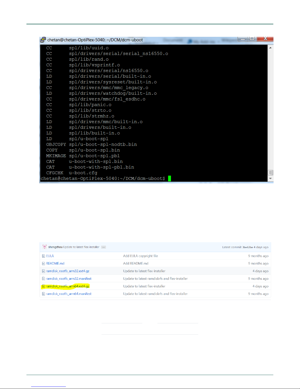
1. Download rootfs for Linux from https://github.com/qoriq-open-source/ramdiskrfs. Download
“ramdisk_rootfs_arm64.ext4.gz” as shown in the snapshot:
2. After download completes, copy “ramdisk_rootfs_arm64.ext4.gz” to a new directory “ramdisk_fs” created in /home/
<user> directory.
NOTE
The below package versions can change without notice.
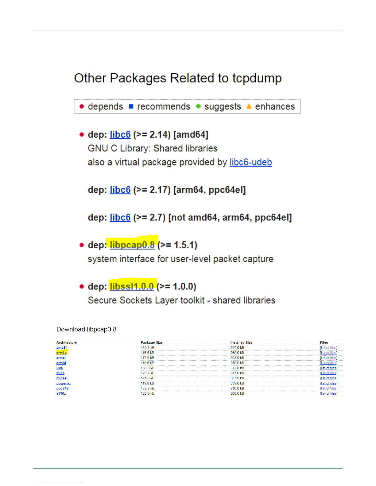
3. Download tcpdump binary from the following link https://packages.debian.org/jessie/arm64/tcpdump/download . Click on
following link ftp.us.debian.org/debian on above webpage. It will download “tcpdump_4.9.2-1_deb8u1_arm64.deb” file.
Copy this to the “ramdisk_fs” directory.
MPC-LS Vehicle Network Processing Evaluation Board User Manual, Rev. 0, Feb 2019
User's Guide
29 / 107
Page 30
NXP Semiconductors
How to build the software for LS1043A and MPC5748G
4. Go to the webpage https://packages.debian.org/jessie/tcpdump and download “libpcap0.8” and “libssl1.0.0” for arm64
architecture. “libpcap0.8_1.6.2-2_arm64.deb” and “libssl1.0.0_1.0.1t-1+deb8u7_arm64.deb” files will be downloaded.
Download from the North America server as highlighted below:
MPC-LS Vehicle Network Processing Evaluation Board User Manual, Rev. 0, Feb 2019
User's Guide
30 / 107
Page 31

NXP Semiconductors
How to build the software for LS1043A and MPC5748G
5. Create directory “libpcap” and “libssl” in “ramdisk_fs”.
6. Move “libpcap0.8_1.6.2-2_arm64.deb” file to “libpcap” and “libssl1.0.0_1.0.1t-1+deb8u7_arm64.deb” file to “libssl”
directory.
7. Go to “libpcap” directory and pass the command “dpkg -x libpcap0.8_1.6.2-2_arm64.deb .”. “usr” folder will be created.
8. Go to “libssl” directory and pass the command “dpkg -x libssl1.0.0_1.0.1t-1+deb8u8_arm64.deb .”.
NOTE
There is a dot at the end of the above command.
9. Go to “ramdisk_fs” directory and run the following command: “dpkg -x tcpdump_4.9.2-1_deb8u1_arm64.deb .”. It will
generate “usr” folder. “tcpdump” binary will get generated in usr/sbin folder.
10. In the “ramdisk_fs” directory run the command “sudo mkdir TEMP”.
>>sudo gunzip ramdisk_rootfs_arm64.ext4.gz
>>sudo mount ramdisk_rootfs_arm64.ext4 TEMP/
>>sudo cp usr/sbin/tcpdump TEMP/sbin/
>>sudo cp libpcap/usr/lib/aarch64-linux-gnu/libpcap.so.0.8 TEMP/usr/lib64
>>sudo cp libpcap/usr/lib/aarch64-linux-gnu/libpcap.so.1.6.2 TEMP/usr/lib64
>>sudo cp libssl/usr/lib/aarch64-linux-gnu/libcrypto.so.1.0.0 TEMP/usr/lib64
>>sudo cp libssl/usr/lib/aarch64-linux-gnu/libssl.so.1.0.0 TEMP/usr/lib64
>>sudo umount TEMP/
>>sudo gzip -9 ramdisk_rootfs_arm64.ext4
11. Copy ramdisk_rootfs_arm64.ext4.gz to /DCM_git/linux directory.
MPC-LS Vehicle Network Processing Evaluation Board User Manual, Rev. 0, Feb 2019
User's Guide
31 / 107
Page 32

NXP Semiconductors
12. Pass the command below in the /DCM_git/linux directory.
mv ramdisk_rootfs_arm64.ext4.gz fsl-image-core-ls1043ardb.ext2.gz
13. Change directory to /DCM_git/linux. Then, run the following commands:
>>export ARCH=arm64
>>export CROSS_COMPILE=aarch64-linux-gnu>>export PATH=$PATH:/home/<user>/DCM_git/gcc-linaro-6.3.1-2017.05-x86_64_aarch64-linux-gnu/bin
14. Run the command: >>make defconfig
15. Run: >>make lsdk.config
How to build the software for LS1043A and MPC5748G
16. Run: >>make -j3.
This command’s runtime is around 30 minutes. It can vary depending on the machine.
MPC-LS Vehicle Network Processing Evaluation Board User Manual, Rev. 0, Feb 2019
User's Guide
32 / 107
Page 33

NXP Semiconductors
How to build the software for LS1043A and MPC5748G
17. Run the command:
>>../u-boot/tools/mkimage -f kernel-ls1043a-rdb.its kernel-ls1043a-rdb.itb
MPC-LS Vehicle Network Processing Evaluation Board User Manual, Rev. 0, Feb 2019
User's Guide
33 / 107
Page 34

NXP Semiconductors
How to build the software for LS1043A and MPC5748G
After successful build, the bin “kernel-ls1043a-rdb.itb” will be created at “../DCM_git/linux/”.
After all the images are built, follow the section LS1043A to learn how to flash the images on MPC-LS VNP EVB.
8.1.4 Linux application for communication with MPC5748G
8.1.4.1 Package 1: socket based communication
To build the socket-based Linux receiver application, follow the below steps:
1. The LS_Rx_App folder inside the ls_ipcf_tx_rx.exe contains the application for LS1043A.
2. Copy the folder to an Ubuntu machine.
3. On terminal, go inside the LS_Rx_App/ls_rx directory that will contain the makefile.
4. Run the below command to set the cross-compile path:
>>export CROSS_COMPILE=/home/<user>/DCM_git/gcc-linaro-6.3.1-2017.05-x86_64_aarch64-linuxgnu/bin/aarch64-linux-gnu-
MPC-LS Vehicle Network Processing Evaluation Board User Manual, Rev. 0, Feb 2019
User's Guide
34 / 107
Page 35

NXP Semiconductors
How to build the software for LS1043A and MPC5748G
5. Pass the command make clean for cleaning all the existing object files.
6. Run make in the same directory to build. An elf ls_rx will be created in ..\ls_rx\build directory. To add the elf
generated to the root file system of the Linux image, follow the below steps:
a. Copy fsl-image-core-ls1043ardb.ext2 to a new directory ramdisk_fs.
b. Copy the executable ls_rx to ramdisk_fs.
c. In the ramdisk_fs directory, make a new directory TEMP.
d. Run the following commands inside the ramdisk_fs directory:
>sudo gunzip fsl-image-core-ls1043ardb.ext2
>sudo mount fsl-image-core-ls1043ardb.ext2 TEMP/
>sudo cp ls_rx TEMP/home/root/
>sudo umount TEMP/
>sudo gzip -9 fsl-image-core-ls1043ardb.ext2
7. Copy this updated fsl-image-core-ls1043ardb.ext2 directory to ../DCM_git/linux directory.
8. Run the below command:
../u-boot/tools/mkimage -f kernel-ls1043a-rdb.its kernel-ls1043a-rdb.itb
The executable ls_rx will be placed in /home/root as Linux is booted on MPC-LS VNP EVB.
8.1.4.2
Package 2: IPCF based communication
To build the IPCF Linux Application, follow the below steps:
1. The ls_ipcf_tx_rx_app folder contains the application for LS1043A.
2. Copy the folder to an Ubuntu machine.
3. On terminal, go inside the ls_ipcf_tx_rx directory that will contain the makefile.
MPC-LS Vehicle Network Processing Evaluation Board User Manual, Rev. 0, Feb 2019
User's Guide
35 / 107
Page 36

NXP Semiconductors
How to build the software for LS1043A and MPC5748G
4. Run the below command to set the cross compile path:
>>export CROSS_COMPILE=/home/<user>/DCM_git/gcc-linaro-6.3.1-2017.05-x86_64_aarch64-linuxgnu/bin/aarch64-linux-gnu-
5. Pass the command make clean for cleaning all the existing object files.
6. Run make in the same directory to build.
An elf ls_ipcf_tx_rx will be created in ../ls_ipcf_tx_rx/build directory.
To add the elf generated to the root file system of the Linux image follow the below steps:
1. Copy fsl-image-core-ls1043ardb.ext2 to a new directory ramdisk_fs.
2. Copy the executable ls_ipcf_tx_rx to ramdisk_fs.
3. In the ramdisk_fs directory, make a new directory TEMP.
4. Run the following commands inside the ramdisk_fs directory:
>sudo gunzip fsl-image-core-ls1043ardb.ext2
>sudo mount fsl-image-core-ls1043ardb.ext2 TEMP/
>sudo cp ls_ipcf_tx_rx TEMP/home/root/
>sudo vi TEMP/etc/profile
a. A new window will open displaying the content of profile. Using the down arrow key come to the bottom of the file.
Note: The user can read about vi editor to edit files in vi editor.
b. Press the “o” button to enable writing in the editor file.
c. Copy the below commands in the file: (Snapshot provided for more clarity)
####### IPCF Application traces ########
echo " "
echo -e "********** \t Linux booted successfully \t *********"
echo " "
echo -e "********** \t Network I/F Configuration \t **********"
if ifconfig eth2 192.168.0.11 ; then
sleep 1s
echo "IP address 192.168.0.11 successfully assigned to eth2 port"
else
echo "IP address 192.168.0.11 not successfully assigned to eth2 port"
fi
sleep 1s
./ls_ipcf_tx_rx get_status
MPC-LS Vehicle Network Processing Evaluation Board User Manual, Rev. 0, Feb 2019
User's Guide
36 / 107
Page 37

NXP Semiconductors
How to build the software for LS1043A and MPC5748G
d. Save the file and exit. For this the user need to press Esc, type “:” and then “wq”. Press Enter.
e. >sudo umount TEMP/
f. >sudo gzip -9 fsl-image-core-ls1043ardb.ext2
5. Copy this updated fsl-image-core-ls1043ardb.ext2 directory to ../DCM_git/linux directory.
6. Run the following command in DCM_git/linux directory to update the kernel itb image:
../u-boot/tools/mkimage -f kernel-ls1043a-rdb.its kernel-ls1043a-rdb.itb
MPC-LS Vehicle Network Processing Evaluation Board User Manual, Rev. 0, Feb 2019
User's Guide
37 / 107
Page 38

NXP Semiconductors
How to build the software for LS1043A and MPC5748G
The executable ls_ipcf_tx_rx will be placed in /home/root as Linux is booted on MPC-LS VNP EVB.
MPC5748G Bare-metal build example
8.2
Install S32 Design Studio for Power Architecture® 2017.R1 - Windows/Linux(REV 2017.R1) from https://www.nxp.com/support/
developer-resources/run-time-software/s32-design-studio-ide/s32-design-studio-ide-for-power-architecture-basedmcus:S32DS-PA?tab=Design_Tools_Tab
For details about installing S32DS for Power Architecture, refer https://www.nxp.com/docs/en/user-guide/DEVKIT-MPC5748G-
SWIG.pdf
To build the bare-metal example codes:
1. Import the whole MPC5748G project into S32DS. For that:
a. Open S32DS
b. Provide a path for the workspace in the dialog box that appears.
c. In the S32DS IDE, go to File ->New -> S32 Project From Example.
MPC-LS Vehicle Network Processing Evaluation Board User Manual, Rev. 0, Feb 2019
User's Guide
38 / 107
Page 39

NXP Semiconductors
d. Go to General -> Existing Projects into workspace
How to build the software for LS1043A and MPC5748G
e. Click on Browse and select the MPC5748G S32DS project source code and click on Finish.
f. The project has been loaded into S32DS workspace.
2. Right-click on the project in the Project Explorer, go to Build configurations -> Build all.
MPC-LS Vehicle Network Processing Evaluation Board User Manual, Rev. 0, Feb 2019
User's Guide
39 / 107
Page 40

NXP Semiconductors
How to build the software for LS1043A and MPC5748G
3. Check if any errors/warnings are generated in the code from the Problems tab(Alt + Shift + Q, then press X).
4. In the Project Explorer, you can see the binary created as shown in the snapshot. Right-click on the binary and select
properties, select the directory where it is placed. This will be used while loading the elf through Lauterbach t32mppc.
MPC-LS Vehicle Network Processing Evaluation Board User Manual, Rev. 0, Feb 2019
User's Guide
40 / 107
Page 41

NXP Semiconductors
8.3 MPC5748G AUTOSAR build
NOTE
NXP has integrated its IPCF communication framework into ARCCORE’s AUTOSAR stack on MPC-LS VNP EVB
under evaluation license from ARCCORE https://www.arccore.com/.
This section provides step by step build guide for ARCCORE's AUTOSAR and IPCF integration. As a pre-requisite
for this section, please contact ARCCORE directly for AUTOSAR stack and Arctic Studio licenses.
1. Request an ARCCORE evaluation account by:
a. Go to www.arccore.com
b. Click on RESOURCES
c. Click on Registration, fill out form and submit
d. Check your email (including junk folder) for reply requesting you to confirm email is correct and confirm.
2. After confirmation of your ARCCORE account, go to www.arccore.com
3. Login to My ARCCORE page.
4. Go to DOWNLOADS section.
How to build the software for LS1043A and MPC5748G
5. Download and install Arctic Studio PPC win32 64bit 17.0.1.
8.3.1 Configuration settings and generation with the help of Arctic Studio 17.0.0
1. Open Arctic Studio 17.0.1 and make a new workspace.
2. Close the Welcome window.
MPC-LS Vehicle Network Processing Evaluation Board User Manual, Rev. 0, Feb 2019
User's Guide
41 / 107
Page 42

NXP Semiconductors
How to build the software for LS1043A and MPC5748G
3. Right-click in the AUTOSAR Navigator window and select import.
MPC-LS Vehicle Network Processing Evaluation Board User Manual, Rev. 0, Feb 2019
User's Guide
42 / 107
Page 43

NXP Semiconductors
How to build the software for LS1043A and MPC5748G
4. Select “General” and “Existing Projects into Workspace” and click on Next.
MPC-LS Vehicle Network Processing Evaluation Board User Manual, Rev. 0, Feb 2019
User's Guide
43 / 107
Page 44

NXP Semiconductors
How to build the software for LS1043A and MPC5748G
5. Click Browse, and select the “core” folder in the project and select OK.
MPC-LS Vehicle Network Processing Evaluation Board User Manual, Rev. 0, Feb 2019
User's Guide
44 / 107
Page 45

NXP Semiconductors
How to build the software for LS1043A and MPC5748G
6. Click “Finish”.
7. The model files will be loaded automatically as the “core” is imported.
MPC-LS Vehicle Network Processing Evaluation Board User Manual, Rev. 0, Feb 2019
User's Guide
45 / 107
Page 46

NXP Semiconductors
How to build the software for LS1043A and MPC5748G
8. Right-click again in the AUTOSAR navigator window and select import.
9. Select General -> Existing projects into workspace->Next->Browse and select the Ethernet simple project available
inside Ethernet Simple example folder as shown in the snapshot.
MPC-LS Vehicle Network Processing Evaluation Board User Manual, Rev. 0, Feb 2019
User's Guide
46 / 107
Page 47

NXP Semiconductors
How to build the software for LS1043A and MPC5748G
10. Click OK and then Finish.
11. Expand “Ethernet Simple” in the AUTOSAR navigator window and double click on the
“EthernetSimple_mpc5748g_mpc574xg_mb_Configuration.arxml”. The
“EthernetSimple_mpc5748g_mpc574xg_mb_Ecu – BSW Editor” will open as shown in the snapshot below.
MPC-LS Vehicle Network Processing Evaluation Board User Manual, Rev. 0, Feb 2019
User's Guide
47 / 107
Page 48

NXP Semiconductors
12. Double-click on TcpIp module.
How to build the software for LS1043A and MPC5748G
13. Expand the “TcpIpConfig” and check if the following subcontainers as shown in the snapshot below are present or not.
If already present skip to step 18.
MPC-LS Vehicle Network Processing Evaluation Board User Manual, Rev. 0, Feb 2019
User's Guide
48 / 107
Page 49

NXP Semiconductors
How to build the software for LS1043A and MPC5748G
14. In the TcpIp, add TcpIpConfig. Right-click on “TcpIpConfig” and choose “Create TcpIpLocalAddr”
15. Right-click on “TcpIpConfig” again, select “Create TcpIpCtrl”.
MPC-LS Vehicle Network Processing Evaluation Board User Manual, Rev. 0, Feb 2019
User's Guide
49 / 107
Page 50

NXP Semiconductors
How to build the software for LS1043A and MPC5748G
16. Right-click on “TcpIpConfig” again, select “Create TcpIpIpConfig”.
17. Right-click on “TcpIpConfig” again, select “Create TcpIpSocketOwnerConfig”.
18. Right-click on “TcpIpSocketOwnerConfig”, create a new TcpIpSocketOwner with name “Ipcf”. See the below snapshot
for reference to set the general settings for this socket owner.
a. Set TcpIpSocketOwnerUpperLayerType to “CDD”.
b. Set TcpIpSocketOwnerHeaderFileName to “cal_ipcf_rx_tx.h”.
c. Set TcpIpSocketOwnerRxIndicationName to “ipcf_asr_rx_indication”.
d. Set TcpIpSocketOwnerLocalIpAddrAssignmentChgName to “demo_local_ip_addr_assignment_chg”
19. Save the configurations using Ctrl+s and click the red cross on the top right side as highlighted in the snapshot below.
MPC-LS Vehicle Network Processing Evaluation Board User Manual, Rev. 0, Feb 2019
User's Guide
50 / 107
Page 51

NXP Semiconductors
20. Double-click on the EthIf Module highlighted below.
How to build the software for LS1043A and MPC5748G
21. Under “EthIfConfigSet”, go to “EthIfController” and click the “Select reference value” button on the right side of “Eth If
Eth Ctrl Ref” as highlighted in the snapshot below.
MPC-LS Vehicle Network Processing Evaluation Board User Manual, Rev. 0, Feb 2019
User's Guide
51 / 107
Page 52

NXP Semiconductors
How to build the software for LS1043A and MPC5748G
22. Select “EthCtrlConfig” under Eth->EthConfigSet as highlighted in the snapshot below and click on OK.
23. Save the configurations using Ctrl+s and click the red cross on the top right side to close the configurations for EthIf
module.
24. Double-click the EcuM Module highlighted below to update it.
MPC-LS Vehicle Network Processing Evaluation Board User Manual, Rev. 0, Feb 2019
User's Guide
52 / 107
Page 53

NXP Semiconductors
How to build the software for LS1043A and MPC5748G
25. Go to EcuM->EcuMCommonConfiguration->EcumSleepMode and click the “select reference value” button for “Ecu
MSleep Mode Mcu Mode Ref” as highlighted in the snapshot below.
26. Select SLEEP for the mpc5748g board as highlighted in the snapshot below and click on OK.
MPC-LS Vehicle Network Processing Evaluation Board User Manual, Rev. 0, Feb 2019
User's Guide
53 / 107
Page 54

NXP Semiconductors
How to build the software for LS1043A and MPC5748G
27. Go to EcuM->EcuMConfiguration->EcuMFixedConfiguration click the “select reference value” button for “Ecu MNormal
Mcu Mode Ref” as highlighted in the snapshot below.
MPC-LS Vehicle Network Processing Evaluation Board User Manual, Rev. 0, Feb 2019
User's Guide
54 / 107
Page 55

NXP Semiconductors
How to build the software for LS1043A and MPC5748G
28. Select RUN for the mpc5748g board as highlighted in the snapshot below and click on OK.
MPC-LS Vehicle Network Processing Evaluation Board User Manual, Rev. 0, Feb 2019
User's Guide
55 / 107
Page 56

NXP Semiconductors
How to build the software for LS1043A and MPC5748G
29. Save the configurations using Ctrl+s and click the red cross on the top right side to close the configurations for EcuM
module.
30. Double-click the OS module highlighted below to update it.
31. Select the “udp_tp_dev_demo_task” under OsTask:s.
32. Do the following general settings for the OsTask:
a. Arc Os Task Stack Size : 4096
b. Os Task Accessing Application : Tick the check box, click the “select reference value” button and select
OsApplication.
c. Set OsTaskActivation to 1
d. Set OsTaskPriority to 2
e. Make sure the OsTaskPriority for all the tasks are as below:
i. MainLWIPTask – 4
ii. OsBswServiceTask – 6
iii. OsRteTask – 3
iv. OsStartupTask – 5
v. Tcpip_task – 5
vi. Udp_mcapi_demo_task - 2
MPC-LS Vehicle Network Processing Evaluation Board User Manual, Rev. 0, Feb 2019
User's Guide
56 / 107
Page 57

NXP Semiconductors
How to build the software for LS1043A and MPC5748G
33. Click OsApplication and add a new Os App Task Ref by clicking on the ‘+’ icon highlighted in the snapshot below.
34. Click the “select reference value” button for this Os App Task Ref and select udp_mcapi_demo_task and click on OK.
MPC-LS Vehicle Network Processing Evaluation Board User Manual, Rev. 0, Feb 2019
User's Guide
57 / 107
Page 58

NXP Semiconductors
How to build the software for LS1043A and MPC5748G
35. Save the configurations using Ctrl+s and click the red cross on the top right side to close the configurations for Os
module.
36. Click Generate symbol on the top right side encircled in the snapshot below.
MPC-LS Vehicle Network Processing Evaluation Board User Manual, Rev. 0, Feb 2019
User's Guide
58 / 107
Page 59

NXP Semiconductors
How to build the software for LS1043A and MPC5748G
37. The console window will show the log of generation. Once the generation is completed a log message displaying
“INFO : Generation complete” will be displayed on the Console window.
38. The generated configurations will be available at “..\examples\EthernetSimple\EthernetSimple\config”.
8.3.2 Integrate the generated configurations to Make system
Integrate the generated BSW configuration and demo application in your make system and import IPCF makefile into your
application makefile. The apps folder inside the /Examples/IPCF/LS1043A directory take care of this part. Copy the generated
configuration files from /EthernetSimple/config/ to /apps/samples/cal_ipcf_rx_tx/config/. Next step is to run the build which will be
covered later in the scope of this document.
A brief description describing the “apps” folder containing the IPCF application is given below:
MPC-LS Vehicle Network Processing Evaluation Board User Manual, Rev. 0, Feb 2019
User's Guide
59 / 107
Page 60

NXP Semiconductors
How to build the software for LS1043A and MPC5748G
1. The “apps” folder is contained outside the core directory for your application.
2. A source folder “cal_ipcf_rx_tx” is inside the apps folder. A folder named “src” will be inside “cal_ipcf_rx” folder. The “src”
folder shall contain 3 more folders inside viz src, config and obj_mpc5748g_mpc574xg_mb.
3. The src folder inside src directory will contain all the .c files that are present in the example Ethernet Simple src folder viz
IoHwAb.c, os_hooks.c, PlatformTasks.c, SwcReader.c and SwcWriter.c along with the application c file cal_ipcf_rx_tx.c
that calls the udp_mcapi_demo_task in it.
4. The “config” folder will contain all the generated files. Copy all the generated configurations from the ethernet simple
example config folder to this folder.
5. obj_mpc5748g_mpc574xg_mb will contain all the generated object files along with the elf once build is done.
6. A shell script “build.sh” will be present that calls the correct paths of AUTOSAR stack(core), the ipcf library and ghs
compiler.
7. The build_config.mk file available at “..\examples\EthernetSimple\EthernetSimple” is copied to the src folder.
8. A makefile is created to append the application header lookup paths, object file list and the list of libraries to include.
8.3.3 Msys and Mingw tool installation
1. Msys and mignw are the tools required to build ipcf application.
2. The setups come installed with Arctic Studio 17.0.1.
3. If not installed, follow the steps at the link “http://www.mingw.org/wiki/MSYS”or directly download from the download links
provided in the section Software requirements.
8.3.4 AUTOSAR source build
1. Open build.sh file in an editor and make sure the paths to the asr_stack, ipcf_root and ghs are correctly set as shown in
the snapshot:
2. The C:\ directory here is accessed using “/c/” and make sure all the paths have a forward slash “/” instead of the general
backward slash “\” in windows.
3. Open msys tool. In its terminal cd to the directory where the build.sh file is kept as shown in the snapshot:
MPC-LS Vehicle Network Processing Evaluation Board User Manual, Rev. 0, Feb 2019
User's Guide
60 / 107
Page 61

NXP Semiconductors
How to flash the board or perform board recovery
4. The build.sh file helps to build the whole AUTOSAR OS along with application written on it into a single executable file.
To obtain the executable, write “./build.sh clean” and then “./build.sh all” on the msys terminal in the present working
directory.
After a successful build, an executable file “cal_ipcf_rx” will be generated in “..\apps\cal_ipcf_rx_tx\src
\obj_mpc5748g_mpc574xg_mb\”
9 How to flash the board or perform board recovery
This section describes the steps to be performed if the MPC5748G or LS1043A memory is unintentionally erased, causing the
board not to boot, or in case new images need to be flashed to the board.
MPC5748G
9.1
Follow the below steps to flash elf to MPC5748G via Lauterbach.
NOTE
Other debuggers like GHS can also be used to perform the same.
1. In T32 PPC package, open t32mppc.exe.
2. To ensure the device starts at reset (before user startup code) using Lauterbach, reset the device using the debugger by
clicking on CPU – In Target Reset:
3. Go to File -> Run Script.
MPC-LS Vehicle Network Processing Evaluation Board User Manual, Rev. 0, Feb 2019
User's Guide
61 / 107
Page 62

NXP Semiconductors
4. Select the cmm script file mpc574xg.cmm provided along with this release.
How to flash the board or perform board recovery
5. Program flash memory confirmation dialog will open, click Yes.
6. Select the enet_rmii_udp_Z4_1.elf executable file provided along with the release and click on Open.
MPC-LS Vehicle Network Processing Evaluation Board User Manual, Rev. 0, Feb 2019
User's Guide
62 / 107
Page 63

NXP Semiconductors
How to flash the board or perform board recovery
7. Now click on “GO icon” to run the executable file on MPC5748G.
8. In case of Package 1, the DS3 LED of MPC5748G will turn on indicating it is working. The executable file on MPC5748G
runs a diagnostic test, testing UART2USB connection, SPI initialization, SJA1105S switch’s valid configuration, and the
SPI2CAN bus. If any of the tests above fail, the DS3 LED is turned off.
Hence, before beginning with the demo, make sure the DS3 LED is not turned off.
LS1043A
9.2
Images can be flashed to LS1043A by either RAM boot via CodeWarrior TAP or by SD boot via an SD card. The steps from basic
setup to flashing binaries in LS1043A are described below:
9.2.1 Using RAM boot
9.2.1.1 CodeWarrior setup
1. Download and install CodeWarrior for Armv8 from “https://www.nxp.com/support/developer-resources/software-
development-tools/codewarrior-development-tools/codewarrior-network-applications/codewarrior-development-suites-fornetworked-applications:CW-DS-NETAPPS?tab=Design_Tools_Tab”
2. Select Download. Sign in at the sign in screen.
MPC-LS Vehicle Network Processing Evaluation Board User Manual, Rev. 0, Feb 2019
User's Guide
63 / 107
Page 64

NXP Semiconductors
How to flash the board or perform board recovery
Figure 12. Downloading Codewarrior Development Suites
3. Select the latest version of CodeWarrior for QorIQ LS Series ARMv8 ISA. Evaluation / Updates as shown in the
preceding figure.
NOTE
The version available on the URL might be different from the one shown in the snapshot. Select the latest version.
Figure 13. Registering a new product
4. Agree to the Software Terms and Conditions by clicking I Agree as shown in the snapshot below.
MPC-LS Vehicle Network Processing Evaluation Board User Manual, Rev. 0, Feb 2019
User's Guide
64 / 107
Page 65

NXP Semiconductors
How to flash the board or perform board recovery
5. Now, select the files as shown in the snapshot and click Download Selected Files.
NOTE
The files might be displayed in a different order than as shown in the figure below.
Figure 14. Downloading the files for installation
MPC-LS Vehicle Network Processing Evaluation Board User Manual, Rev. 0, Feb 2019
User's Guide
65 / 107
Page 66

NXP Semiconductors
6. Let the download complete.
How to flash the board or perform board recovery
7. After the download is completed go to the directory where the file has been saved and install CodeWarrior Networked
Applications Windows Hosted-Offline v2017.03.exe as shown in the snapshot below.
Figure 15. Installing the CCS application
8. In the Install Wizard, accept the NXP Software License Agreement and click Next.
MPC-LS Vehicle Network Processing Evaluation Board User Manual, Rev. 0, Feb 2019
User's Guide
66 / 107
Page 67

NXP Semiconductors
How to flash the board or perform board recovery
9. Agree to the Linaro License Agreement by clicking I Agree as shown in the snapshot below.
MPC-LS Vehicle Network Processing Evaluation Board User Manual, Rev. 0, Feb 2019
User's Guide
67 / 107
Page 68

NXP Semiconductors
How to flash the board or perform board recovery
10. In the Choose Components windows, choose the default files as shown in the snapshot below.
MPC-LS Vehicle Network Processing Evaluation Board User Manual, Rev. 0, Feb 2019
User's Guide
68 / 107
Page 69

NXP Semiconductors
How to flash the board or perform board recovery
11. A temporary license file for 15 days will be generated. One can register with NXP to receive a permanent license.
MPC-LS Vehicle Network Processing Evaluation Board User Manual, Rev. 0, Feb 2019
User's Guide
69 / 107
Page 70

NXP Semiconductors
How to flash the board or perform board recovery
12. After the installation completes, launch the CW IDE.
Option 1: “C:\Freescale\CW4NET_v2017.03\CW_ARMv8” and open “fsl_eclipse.bat”.
Option 2: Search from the Windows Start menu, CodeWarrior for Armv8.
13. Create a workspace as shown below
MPC-LS Vehicle Network Processing Evaluation Board User Manual, Rev. 0, Feb 2019
User's Guide
70 / 107
Page 71

NXP Semiconductors
14. Close the Welcome window.
How to flash the board or perform board recovery
15. Now click on the Open Perspective window option on the top right part of the screen, then select Debug and click OK.
MPC-LS Vehicle Network Processing Evaluation Board User Manual, Rev. 0, Feb 2019
User's Guide
71 / 107
Page 72

NXP Semiconductors
How to flash the board or perform board recovery
16. Click on Target Connections, find LS1043A_RDB board, right-click on it and click on “Duplicate”.
Why duplicate:
Because the predefined configurations for evaluation systems
• Cannot be deleted
• Can only be duplicated for customization
MPC-LS Vehicle Network Processing Evaluation Board User Manual, Rev. 0, Feb 2019
User's Guide
72 / 107
Page 73

NXP Semiconductors
How to flash the board or perform board recovery
17. Give a new name to the board and click on OK. The new board will now come at the top of the board list.
Figure 16. Target Connections window
18. Double-click on your new board name MPC-LS-VNP-EVB, the Target Connection Configuration window will open
up on the left hand side. First make sure the device selected is LS1043A, then change the timeout (seconds) to “60”.
Now change the tab to Target Initialization File.
Figure 17. Configuring the Target Connection
19. In the Target Initialization File tab, set “USE_SAFE_RCW” to “True” and change the value of “BOOT_CHIP_SELECT”
to 2.
Figure 18. Specifying the options in the Target Initialization File tab
20. Save the configurations by using the Ctrl + S key combination.
MPC-LS Vehicle Network Processing Evaluation Board User Manual, Rev. 0, Feb 2019
User's Guide
73 / 107
Page 74

NXP Semiconductors
How to flash the board or perform board recovery
9.2.1.2 CodeWarrior TAP connection
Connect the mini USB cable from CodeWarrior TAP to your windows machine. Also connect the JTAG connector of CodeWarrior
on J16 JTAG of MPC-LS-VNP-EVB as described in Section CodeWarrior TAP.
9.2.1.3 JTAG connection diagnostic
To ensure JTAG connection is working fine, below tests need to be conducted.
In the CodeWarrior IDE, click Diagnose Connection for JTAG connection diagnostics in the Target Connections tab.
Figure 19. Diagnosing the JTAG connection
If the board is not powered on, or the CodeWarrior TAP is not connected to the board, Connection Diagnostics will throw the
below error:
If JTAG is successfully connected, the Connection Diagnostics window will show all the tests with a small green tick on the front
of each row.
MPC-LS Vehicle Network Processing Evaluation Board User Manual, Rev. 0, Feb 2019
User's Guide
74 / 107
Page 75

NXP Semiconductors
How to flash the board or perform board recovery
NOTE
In cases where network diagnostics problem is faced, follow the steps mentioned in CodeWarrior CCS on page
96.
9.2.1.4 Flashing U-Boot in LS1043A
In this section, the U-Boot image is loaded into the DRAM section.
1. Click Configure Target Connections, right-click on the MPC-LS-VNP-EVB and select Edit.
Figure 20. Configuring target connections for MPC-LS-VNP-EVB
MPC-LS Vehicle Network Processing Evaluation Board User Manual, Rev. 0, Feb 2019
User's Guide
75 / 107
Page 76

NXP Semiconductors
How to flash the board or perform board recovery
2. In the Target Init File tab, delete the text and paste the TargetInit.txt file contents.TargetInit.txt is provided along with the
package. Perform this activity twice to reflect the change in the file.
Figure 21. Target Init Editor
3. Click on OK. Close the Target Configuration Window.
MPC-LS Vehicle Network Processing Evaluation Board User Manual, Rev. 0, Feb 2019
User's Guide
76 / 107
Page 77

NXP Semiconductors
How to flash the board or perform board recovery
Figure 22. Closing the Target Configuration Window
4. Click on Connect (see arrow below).
5. Go to Window -> Show View -> Memory.
MPC-LS Vehicle Network Processing Evaluation Board User Manual, Rev. 0, Feb 2019
User's Guide
77 / 107
Page 78

NXP Semiconductors
How to flash the board or perform board recovery
6. Go to the Memory tab, click the green plus sign, enter the address as 0x82000000, and press OK.
MPC-LS Vehicle Network Processing Evaluation Board User Manual, Rev. 0, Feb 2019
User's Guide
78 / 107
Page 79

NXP Semiconductors
How to flash the board or perform board recovery
7. Go to 0x82000000 address and select HEX view. Note: If the view is already hex, continue with the next step.
8. Click Import.
MPC-LS Vehicle Network Processing Evaluation Board User Manual, Rev. 0, Feb 2019
User's Guide
79 / 107
Page 80

NXP Semiconductors
How to flash the board or perform board recovery
9. Select the Format as Raw Binary, check the address is 0x82000000, and load the u-boot-dtb_ramboot.bin file and
Press OK. The memory address provided is a part of the DRAM section. Note: The user has already built this image in
the DDR boot.
10. The bin file will be transferred to 0x82000000 address.
MPC-LS Vehicle Network Processing Evaluation Board User Manual, Rev. 0, Feb 2019
User's Guide
80 / 107
Page 81

NXP Semiconductors
How to flash the board or perform board recovery
11. Execute Tera Term.
12. Select the serial option in Tera Term and ensure that USB serial port is selected and click OK.
13. Select Setup > Serial port.
MPC-LS Vehicle Network Processing Evaluation Board User Manual, Rev. 0, Feb 2019
User's Guide
81 / 107
Page 82

NXP Semiconductors
How to flash the board or perform board recovery
14. Configure the serial port of the host machine with the following settings:
• Baud Rate:115200 bits/s
• Number of data bits: 8
• Parity : None
• Number of stop bits: 1
• Flow Control: Hardware/None
15. Now in the CodeWarrior IDE, click on resume and access U-boot at the Tera Term console.
MPC-LS Vehicle Network Processing Evaluation Board User Manual, Rev. 0, Feb 2019
User's Guide
82 / 107
Page 83

NXP Semiconductors
How to flash the board or perform board recovery
The board boots up and the console shows the U-Boot messages as shown in the image below.
To reach U-Boot prompt, press any key to stop autoboot.
9.2.1.5 Flashing images from U-Boot console via serial port
The user has two available options to flash the images on MPC-LS-VNP-EVB.
• Serial port
• Ethernet port
Users are recommended to use Ethernet port to flash images on the board as the speed of flashing in case of Ethernet is much
higher.
MPC-LS Vehicle Network Processing Evaluation Board User Manual, Rev. 0, Feb 2019
User's Guide
83 / 107
Page 84

NXP Semiconductors
NOTE
If you have flashed binaries of Getting Started package 2 on the MPC5748G side, set the speed of the Ethernet
port to 100 Mbps Full Duplex in the Ethernet adapters. To do so, go to Network and Sharing Center -> Change
adapter settings. Right-click on Local Area Connection -> Properties -> Networking Tab -> Configure ->
Advanced Tab -> Speed & Duplex -> Set value to 100 Mbps Full Duplex.
The default software flashed to the boards is Getting Started Package 2.
For Getting Started package 1, the user needs to set this value to Auto Negotiation.
How to flash the board or perform board recovery
The user may skip the below section of serial flashing and jump to section 9.2.1.6 Flash images from u-boot console via ethernet
port for flashing via Ethernet.
1. Write the command “sf probe” and press enter. NOR memory must be detected.
2. On the U-Boot shell, write “loady” and press enter.
3. Now go to File -> Transfer -> YMODEM -> send.
MPC-LS Vehicle Network Processing Evaluation Board User Manual, Rev. 0, Feb 2019
User's Guide
84 / 107
Page 85

NXP Semiconductors
How to flash the board or perform board recovery
4. Select the “u-boot-dtb_qspi.bin” file and click on “Open”. This is the U-Boot image for NOR memory.
5. Let the transfer complete.
6. Once the transfer completes, write the following commands on Tera Term console:
sf erase 0x100000 0x100000
Press enter. Then, run the command:
sf write 0x90000000 0x100000 0x100000
7. Now again type “loady” on the console, press enter, go to File -> Transfer -> YMODEM -> send and select the
“rcw_1600_qspiboot_swapped.bin” file and click on “Open”.
8. Now write the following commands on the console:
sf erase 0x0 0x100000
MPC-LS Vehicle Network Processing Evaluation Board User Manual, Rev. 0, Feb 2019
User's Guide
85 / 107
Page 86

NXP Semiconductors
How to flash the board or perform board recovery
Press enter. Then, run the command:
sf write 0x90000000 0x0 0x100000
9. Now again type “loady” on the console, press enter, go to File -> Transfer -> YMODEM -> send and select the “ppa.itb”
file and click on “Open”.
10. Now run the following commands on the console:
sf erase 0x400000 0x100000
Press enter. Then run:
sf write 0x90000000 0x400000 0x100000
11. Now again type “loady” on the console, press enter, go to File -> Transfer -> YMODEM -> send and select the
“fsl_fman_ucode_ls1043_r1.1_106_4_18.bin” file and click on “Open”.
12. Now write the following commands on the console:
sf erase 0x900000 0x100000
Press enter. Then run:
sf write 0x90000000 0x900000 0x100000
13. The size of the kernel image is huge and it is recommended to flash it via Ethernet port only.
14. Give a hard reset to the LS1043A by pressing the LS-RST button on MPC-LS VNP EVB.
15. Stop the down counter by pressing enter to access the U-Boot console.
16. To flash the Linux image, the user needs to follow the step 8e in the section Flash images from u-boot console via
ethernet port.
MPC-LS Vehicle Network Processing Evaluation Board User Manual, Rev. 0, Feb 2019
User's Guide
86 / 107
Page 87

NXP Semiconductors
How to flash the board or perform board recovery
9.2.1.6 Flashing images from U-Boot console via MPC-LS Processor Module ethernet port
1. Connect the MPC-LS Processor Module ethernet port to your PC using an Ethernet cable.
2. Assign “192.168.1.1” as the IP address to your PC by going in the Network and Sharing Center. Go to Change
adapter settings.
3. Right-click on the Local area connection set between PC and MPC-LS VNP EVB and select Properties.
4. Double-click on Internet Protocol Version 4 (TCP/IPv4) and assign the ip as shown in the image and click on “OK”.
MPC-LS Vehicle Network Processing Evaluation Board User Manual, Rev. 0, Feb 2019
User's Guide
87 / 107
Page 88

NXP Semiconductors
How to flash the board or perform board recovery
5. Enter these commands at the U-Boot prompt to enable Ethernet.
setenv ethact FM1@DTSEC9
setenv ethaddr 00:04:9F:03:D9:D7
setenv eth1addr 00:04:9F:03:D9:D8
setenv eth2addr 00:04:9F:03:D9:D9
setenv eth3addr 00:04:9F:03:D9:DA
setenv eth4addr 00:04:9F:03:D9:DB
setenv eth5addr 00:04:9F:03:D9:DC
setenv eth6addr 00:04:9F:03:D9:DD
setenv eth7addr 00:04:9F:03:D9:DE
setenv ipaddr 192.168.1.34
setenv serverip 192.168.1.1
saveenv
ping 192.168.1.1
MPC-LS Vehicle Network Processing Evaluation Board User Manual, Rev. 0, Feb 2019
User's Guide
88 / 107
Page 89

NXP Semiconductors
Save your settings to flash using the saveenv command so that it can be used after reboot.
Use the edit command to edit any Environment variable when it is already present, else use setenv for first time.
Edit command usage: edit eth1addr and press Enter, the initial value of the variable will be displayed that can
be edited. Press Enter after the new value is set.
NOTE
How to flash the board or perform board recovery
6. Open the prior downloaded tool tftp64 and make sure the IP address assigned to the eth port connected to MPC-LS
VNP EVB is visible in Server interfaces. (Image shown after step 7)
Note: Add the tftp port to windows firewall settings if not already done. To add go to windows firewall -> advanced settings
-> inbound rules, Right-click on inbound rule and select new rule option, select port option select port, click next and select
UDP and mention 69 as the port number, give TFTP name to it.
7. Make sure the directory that is mentioned in the tftp “Current directory” has the kernel image “kernel-ls1043a-rdb.itb”
provided along with this package.
MPC-LS Vehicle Network Processing Evaluation Board User Manual, Rev. 0, Feb 2019
User's Guide
89 / 107
Page 90

NXP Semiconductors
How to flash the board or perform board recovery
8. Execute the below commands to flash the images:
RCW
a.
tftp 0x90000000 rcw_1600_qspiboot_swapped.bin
sf probe
sf erase 0x0 0x100000
sf write 0x90000000 0x0 0x100000
U-Boot
b.
tftp 0x90000000 u-boot-dtb_qspi.bin
sf probe
sf erase 0x100000 0x100000
sf write 0x90000000 0x100000 0x100000
PPA
c.
tftp 0x90000000 ppa.itb
sf probe
MPC-LS Vehicle Network Processing Evaluation Board User Manual, Rev. 0, Feb 2019
User's Guide
90 / 107
Page 91

NXP Semiconductors
sf erase 0x400000 0x100000
sf write 0x90000000 0x400000 0x100000
Fman
d.
tftp 0x90000000 fsl_fman_ucode_ls1043_r1.1_106_4_18.bin
sf probe
sf erase 0x900000 0x100000
sf write 0x90000000 0x900000 0x100000
Linux
e.
tftp 0xa0000000 kernel-ls1043a-rdb.itb
nand info
nand erase $kernel_start $kernel_size
nand write $load_addr $kernel_start $kernel_size
For the tftp server to run make sure in “Control Panel\All Control Panel Items\Programs and Features\Turn Windows
features on or off” TFTP client is enabled.
How to flash the board or perform board recovery
If the server still does not work, contact IT support.
9. Now simply reset the MPC-LS VNP EVB and let the autoboot complete.
10. The Linux image is loaded into the NAND memory. As the default boot of every board is NOR, the U-Boot is booted
from NOR and the Linux image is booted from the NAND flash.
MPC-LS Vehicle Network Processing Evaluation Board User Manual, Rev. 0, Feb 2019
User's Guide
91 / 107
Page 92

NXP Semiconductors
How to flash the board or perform board recovery
11. The Linux shell will ask for login, enter root and press Enter. The Linux shell is up.
9.2.2 Using SD boot
9.2.2.1 Hardware settings
For SD boot, follow the hardware settings as mentioned in Resistor configurations on page 6
By default, R85 and R493 are not installed. Hence, simply install R493 (4.7K) to change the board boot mode to SD boot.
9.2.2.2 Flashing software
Connect the SD card on a Linux Ubuntu machine. Check the device name using the command sudo fdisk -l. (In this case, the
device name is /dev/sde1, hence sde is the main device. So, we use /dev/sde as the device name.)
Prepare SD card to flash the required images later:
1. export DEVSD=/dev/sde
2. sudo fdisk ${DEVSD}
3. Press “d”. (Repeat unitl all the partitions are deleted)
4. Press “n”. This creates a new partition.
5. Press “p”. This creates a primary partition.
6. Press “1”. The first partition.
7. Press Enter. This will create a partition that starts at offset 2048.
8. Press “t”. To set partition type.
9. Press “1” to select partition number 1. Note: If “1” is already entered in the command and displayed, directly go to the
next step.
10. Now type “83” to select Linux file system.
11. Press “w”. This writes the partition table and fdisk exits
12. This newly created partition need to be formatted to be usable. Firstly, remove and put SD Card back into its slot, then
run the following commands to format the partition:
sudo mkfs.ext3 -L rootfs ${DEVSD}1
Now copy all the binaries (U-Boot, fman, ppa, Linux) in a single directory on Ubuntu machine, and execute the following set of
commands to flash them on SD card.
NOTE
RCW is a part of the U-Boot image in case of SD, hence it will not be flashed separately.
Flash SD card:
1. U-Boot: u-boot: u-boot-with-spl-pbl_sd.bin(image build as in section SD Boot)
sudo dd if=u-boot-with-spl-pbl_sd.bin of=/dev/ sde bs=512 seek=8
2. PPA: ppa.itb
sudo dd if=ppa.itb of=/dev/sde bs=512 seek=8192
3. Fman: fsl_fman_ucode_ls1043_r1.1_106_4_18.bin
sudo dd if=fsl_fman_ucode_ls1043_r1.1_106_4_18.bin of=/dev/sde bs=512 seek=18432
MPC-LS Vehicle Network Processing Evaluation Board User Manual, Rev. 0, Feb 2019
User's Guide
92 / 107
Page 93

NXP Semiconductors
How to run the application
4. Linux: kernel-ls1043a-rdb.itb
sudo dd if=kernel-ls1043a-rdb.itb of=/dev/sde bs=512 seek=32768
Put the SD card into the micro SD card slot and power on MPC-LS VNP EVB to view the U-Boot and Linux console.
10 How to run the application
This section describes the steps for running the applications of both the getting started packages on LS1043A and MPC5748G.
10.1 LS1043A
10.1.1 Package 1: Socket based application
On the Linux console, write the below commands:
1. >>ifconfig eth2 192.168.0.11 up
2. >>./ls_rx
NOTE
Make sure the binary flashed to MPC5748G is the one provided in the package 1.
10.1.2 Package 2 IPCF Linux application
The default application on Linux runs as soon as the user login into the shell. This application assigns the eth2 port of LS1043A
with an ip address of 192.168.0.11 and executes the “get_status” command that sends the “get_status” command to MPC5748G
and then receive the response and status back from it. In case MPC5748G fails to respond, LS1043A exits the application after
a wait time of 5 seconds.
Note 1: Make sure the binary flashed to MPC5748G is the one provided in the package 2.
Note 2: For Windows 10, the serial COM port will not be detected, and the CDM v2.12.28 WHQL driver must be installed for it.
For steps to install the driver refer the quick start guide for MPC-LS-VNP-EVB.
MPC-LS Vehicle Network Processing Evaluation Board User Manual, Rev. 0, Feb 2019
User's Guide
93 / 107
Page 94

NXP Semiconductors
How to run the application
If the user wants to run the application again, follow the below step:
1. ./ls_ipcf_tx_rx <command>
<command> accepts the following parameters as input:
• get_status : LS1043A seeks status from MPC5748G, waits for response and MPC5748G responds with the status of switch
initialization, spi initialization, tcpip initialization and successful LS1043A out of reset. LS1043A prints the status on console.
• led_on : Sends command to MPC5748G to switch the DS3 LED on.
• led_off : Sends command to MPC5748G to switch the DS3 LED off.
Help menu is displayed if the user leaves the command field empty.
The output of the commands are as shown below:
• get_status:
MPC-LS Vehicle Network Processing Evaluation Board User Manual, Rev. 0, Feb 2019
User's Guide
94 / 107
Page 95

NXP Semiconductors
• led_on:
How to run the application
• led_off:
MPC-LS Vehicle Network Processing Evaluation Board User Manual, Rev. 0, Feb 2019
User's Guide
95 / 107
Page 96

NXP Semiconductors
CodeWarrior CCS
10.2 MPC5748G
The application runs as soon as the executable file is flashed to it for both bare-metal and AUTOSAR software (i.e. for both package
1 and package 2).
In the case of bare-metal software, MPC5748G sends UDP packets to LS1043A continuously.
In the case of AUTOSAR software, MPC5748G waits to receive command from LS1043A over IPCF.
A
CodeWarrior CCS
Step 1: Verify that the license file is correct. To check this, go to menu bar, click “Help” – NXP Licenses.
Step 2: Cross-check that the TAP is configured for USB.
1. In the Target Connections window, right-click on the MPC-LS-VNP-EVB and select Edit.
MPC-LS Vehicle Network Processing Evaluation Board User Manual, Rev. 0, Feb 2019
User's Guide
96 / 107
Page 97

NXP Semiconductors
2. In the Target Connection Configurator window that opens, click the USB button if not already selected.
CodeWarrior CCS
Step 3:
1. The CodeWarrior tools communicate with the TAP run controllers through a CodeWarrior Connection.
2. The CodeWarrior connection server console can be used to cross-check if the CodeWarrior TAP is connected during a
task like “inspect” in the previous test is running.
3. Open CCS from the Show hidden icons popup as shown in the snapshot below or go to “..\Freescale
\CW4NET_v2017.03\Common\CCS\bin” and open ccs.
MPC-LS Vehicle Network Processing Evaluation Board User Manual, Rev. 0, Feb 2019
User's Guide
97 / 107
Page 98

NXP Semiconductors
4. Write “show cc” to see the CodeWarrior TAP connected.
CodeWarrior CCS
5. Configure the CodeWarrior TAP by deleting the previous configurations, configure it again for the USB port it is
connected to by executing the commands as shown in the snapshot.
MPC-LS Vehicle Network Processing Evaluation Board User Manual, Rev. 0, Feb 2019
User's Guide
98 / 107
Page 99

NXP Semiconductors
Running 64-bit guest on VirtualBox
6. After the above commands, the user needs to run the below commands:
>>>ccs::config_chain {ls1043a dap sap2}
>>display ccs::get_config_chain
CC console log that will be displayed is:
• CodeWarrior TAP executable differs from local file.
• CodeWarrior TAP Boot Loader version 1.0.1
• CodeWarrior TAP OS version 1.0.1
• Sending code to CodeWarrior TAP.......done
• Running package script
• 0: CodeWarrior TAP (cwtap) CC software ver. {0.0}
• (bin) 9 % ccs::config_chain {ls1043a dap sap2}
• (bin) 10 % display ccs::get_config_chain
• Chain Position 0: LS1043A
• Chain Position 1: DAP
• Chain Position 2: SAP2
Refer to https://www.nxp.com/docs/en/application-note/AN4384.pdf
B
Running 64-bit guest on VirtualBox
1. Enable Intel Virtualization.
a. Enter BIOS of your Machine (The example steps shown here are using Dell laptop):
MPC-LS Vehicle Network Processing Evaluation Board User Manual, Rev. 0, Feb 2019
User's Guide
99 / 107
Page 100

NXP Semiconductors
i. Restart your laptop, press and hold "F2" on the computer keyboard when the Dell logo appears on the
ii. Drop down to Virtualization support.
iii. Enable Virtualization (if not already enabled) as shown below. If already enabled, save and reboot the
b. Once Intel Virtualization is enabled, enable the VT for Direct I/O(below Virtualization) as well if your BIOS has this
option.
c. Save and reboot the machine.
Running 64-bit guest on VirtualBox
screen. The computer will enter the system setup program to display information stored in BIOS.
machine.
2. Disable the group policy setting that is used to enable Credential Guard.
a. Click Start > Run, type gpedit.msc, and click Ok. The Local group Policy Editor opens.
b. Go to Local Computer Policy > Computer Configuration > Administrative Templates > System > Device
Guard > Turn on Virtualization Based Security.
c. Select Disabled.
3. Disable Hyper-V in Windows 10. To do so follow the below steps:
a. Control Panel -> Programs and Features -> Turn Windows Features on or off. Uncheck the Hyper-V
checkbox and click on OK.
MPC-LS Vehicle Network Processing Evaluation Board User Manual, Rev. 0, Feb 2019
User's Guide
100 / 107
 Loading...