

Page 1
Quick Start Guide
MPC5777C-DEVB
NXP automotive system solution with the highly integrated
SPC5777C MCU as well as the advanced MC33FS6520LAE
system basis chip and the TJA1100 and TJA1145T/FD Ethernet
and CAN FD Physical interface chips
FREEDOM DEVELOPMENT PLATFORM
Page 2
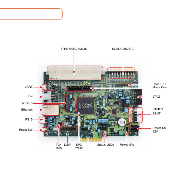
GET TO KNOW THE MPC5777C-DEVB BOARD
eTPU A/B/C eMIOS SDADC/eQADC
2
UART
NEXUS
Ethernet
PS15
Reset SW
User LEDs
Motor Control IF
LIN
TJA
1100
DSPI SPC
5777C
Power SWStatus LEDs
JTAG
CANFD
SENT
Power Socket
12V
Figure 1: Top elevation of MPC5777C Development Board
Page 3

www.nxp.com
MPC5777C-DEVB FEATURES
The standalone development board provides the following features:
• NXP MPC5777C Microcontroller (516 MAPBGA soldered)
• 40MHz onboard clock oscillator circuit for MCU Clocking
• User reset switch with reset status LEDs
• Power switch with Power Indication LEDs
• 4 user LEDs, freely connectable
• Standard 14-pin JTAG debug connector and 50-pin SAMTEC Nexus connector
• Micro USB / UART FDTI transceiver to interface with MCU
• NXP FS65xx Power SBC for standalone operation of MCU
• Single 12 V external power supply input to on-board Power SBC providing all of
the necessary MCU voltages; power supplied to the DEVB via a 2.1mm barrel style
power jack
• 1 CAN and 1 LIN connector supported by Power SBC
• 1 CAN supported via NXP CANFD transceiver TJA1145
• 1 Automotive Ethernet supported via NXP Ethernet physical interface TJA1100
• Analog/eTPU/eMIOS/DSPI/SENT/PSI5 signals available via on board connectors
• Motor Control Interface to connect with power stage board of MTRCKTSPS5744P
Development Kit
3
Page 4

MPC5777C-DEVB HARDWARE MPC5777C-DEVB PACKAGE
The development board includes a
complete NXP system solution. Following
table describes the NXP components
used in the DEVB.
Microcontroller
The SPC5777C offers 264MHz lockstep
cores to support ASIL-D, 8 MB of Flash,
512 KB SRAM, CAN-FD, Ethernet,
advanced complex timers and a CSE
hardware security module.
System Basis Chip
The MC33FS6520LAE is providing robust,
scalable power management to the
SPC5777C MCU with Fail Silent safety
monitoring measures that fit for ASIL D.
Ethernet PHY
The TJA1100 is a 100BASE-T1 compliant
Ethernet PHY optimized for automotive
use cases. The device provides 100 Mbit/s
transmit and receive capability over a
single Unshielded Twisted Pair cable.
CANFD PHY
The TJA1145T/FD Automotive 2Mbps
CANFD physical layer interface chip
4
• NXP MPC5777C Automotive
Microcontroller board
• 12V Power Supply
• Micro USB Cable
• Universal Power Adapter
Page 5

STEP-BY-STEP INSTRUCTIONS
www.nxp.com
This section covers software download,
development kit setup, and application
control.
Download
1
Software
Download installation software
and documentation at
nxp.com/MPC5777C-DEVB.
Download Necessary
2
Drivers
Install the FT230x virtual COM port driver.
Visit ftdichip.com/drivers/vcp.htm to
download the correct driver. Select the
virtual COM port (VCP) driver based on
your operating system and processor
architecture.
Install
3
FTDI Driver
Go to the Device Manager and rightclick the COM port detected and select
Update Driver Software.
Select Browse my computer for driver
software and select the FTDI driver that
has been downloaded.
Restart your machine.
Connect the
4
power supply
Connect power supply to power socket
and micro USB cable to micro USB port
on the Development board. Turn on the
Power Switch. Make sure the status LEDs
D14, D15 and D16 for voltage levels 3.3V,
5V and 1.25V respectively are glowing on
the board.
5
Page 6

STEP-BY-STEP INSTRUCTIONS CONTINUED
Setup Tera
5
Term Console
Open Tera Term on Windows PC. Select
the serial port to which the micro USB of
the Development board is connected and
click OK. Go to Setup>Serial Port and
select 19200 as the baud rate.
Reset the
6
Board
Press the Reset button on the
Development board. Welcome message
will be printed in the Tera Term window
as shown below.
6
Page 7

MPC5777C-DEVB REFERENCES
• MPC5777C Reference Manual
• MPC5777C Data sheet
• MPC5777C Errata
• MPC5777C Hardware Requirements/Example Circuits
www.nxp.com
7
Page 8

SUPPORT
Visit www.nxp.com/support for a list of
phone numbers within your region.
WARRANTY
Visit www.nxp.com/warranty for complete
warranty information.
Get Started
Download installation
software and documentation at
nxp.com/MPC5777C-DEVB.
AUTOMOTIVE COMMUNITY:
https://community.nxp.com/community/s32
MPC57XXX COMMUNITIES:
https://community.nxp.com/community/
s32/mpc5xxx
www.nxp.com
NXP and the NXP log o are trademar ks of NXP B.V. All other prod uct or s erv ice name s are the p roper ty of
their re spec tive owners. © 2 019 NXP B.V.
Docum ent Number: MPC5777CDEV BQSG RE V 0
 Loading...