

Page 1

Based on i.MX 8MQuad Application Processor
Quick Start Guide
Evaluation Kit
i.MX 8MQuad EVK CPU Board
NXP Confidential and Proprietary
Preliminary, Subject to Change
Page 2

Quick Start Guide
2
USB Type-A
Connector
GET TO KNOW THE EVK BASED ON i.MX 8MQUAD APPLICATION
PROCESSOR
Infrared
Receiver
BOOT DEVICE switch
DC Jack for 12V
power input
Power Switch
3.5mm
Audio Jack
USB Type-C
Connector
SD card
Connector
1Gbps Ethernet
Connector
Debug port
Debug port LEDs
JTAG
Connector
BOOT MODE switch
MIPI-CSI2
Connector
RESET Button
Figure 1: Main interfaces of i.MX 8MQ EVK CPU Board
HDMI
Connector
MIPI-CSI1
Connector
Power
Indication LED
ON/OFF
Button
MIPI-DSI
Connector
Page 3

www.nxp.com
3
FPC Connector
used to connect
Audio Board
Figure 2 : Bottom View of i.MX 8MQ EVK CPU Board
NXP Confidential and Proprietary
Preliminary, Subject to Change
M.2 Connector
Page 4

Quick Start Guide
4
ABOUT THE EVALUATION KIT BASED ON THE i.MX 8MQUAD
The Evaluation Kit (EVK) based on i.MX
8MQuad introduces developers to the
i.MX 8MQuad application processor. To
speed up development, hardware design
files, tools and board support packages
(BSPs) for Linux® , FreeRTOS™ and
Android are available for the customers.
The i.MX 8MQuad EVK consists of a
CPU board and an audio board
(ordered separately).
The audio board is used to support
extended audio features.
NXP Confidential and Proprietary
Preliminary, Subject to Change
Page 5

www.nxp.com
5
FEATURES
The following features are available with the EVK CPU board based on the
i.MX 8 MQuad applications processor:
•
i.MX 8MQuad processor with 5 cores
(4×ARM® Cortex®-A53, and 1× CortexM4)
•
3GB, 32-bit LPDDR4 with 1.6 GHz clock
•
eMMC 5.0, 16GB
•
32MB Octal SPI NOR flash
•
Micro SD card connector
•
USB3.0 Type-C connector with PD
support
•
USB3.0 Type-A connector
•
HDMI2.0a Type-A connector
•
1Gbps Ethernet
•
mini-SAS MIPI-DSI connector
•
2x mini-SAS MIPI-CSI connectors for
camera
•
USB to serial convertor for debug
•
Infrared receiver
•
On-board MIMO 2x2 WiFi and BT4.1
•
LEDs for power indication and generalpurpose use
•
M.2 connector for WiFi/BT (PCIe, USB,
UART, I2C and I2S)
•
3.5mm Audio Jack for amplified speakers
•
JTAG 10-Pin connector
NXP Confidential and Proprietary
Preliminary, Subject to Change
Page 6

Quick Start Guide
6
GETTING STARTED
This section describes how to use the EVK and the required accessories to develop
applications using the kit.
Unpacking
the Kit
The EVK is shipped with the items listed in Table 1. Ensure the items are available in the
i.MX 8MQuad EVK.
ITEM
DESCRIPTION
CPU board
CPU board with i.MX 8MQuad processor, memory and PMIC
Power supply
Output: DC 12V/5A, Plug: 1.65mm x 5.15mm
USB Type-C
Cable
Cable -Assembly, USB 3.0 Type-A Male, USB micro-B Male, Shielded,
1m
USB micro-B
Cable
Cable -Assembly, USB 2.0 Type-A Male, USB Type-C Male, Shielded,
1m
Documentation
Quick Start Guide
Table 1: Contents of the i.MX 8MQuad Evaluation Kit
1
NXP Confidential and Proprietary
Preliminary, Subject to Change
Page 7

www.nxp.com
7
Prepare
Accessories
The following items in Table 2 are required to run the i.MX 8MQuad EVK.
ITEM
DESCRIPTION
HDMI display
and cable
HDMI display and cable is required to run the HDMI
Mouse
Mouse with USB interface
Table 2: Necessary Equipment provided by customer
2
Page 8

Quick Start Guide
8
Download
Software and
Tools
Download installation software and documentation at www.nxp.com/iMX8MQEVK
(address may need to be updated). The following documents are available on the
website:
ITEM
DESCRIPTION
Documentation
• Schematics, layout and Gerber files
• Quick Start Guide
Software
Development
Linux BSPs, Android BSPs
Demo Images
Copy of the latest Linux BSP images and Android images that are
available to program on to the eMMC
Table 3: Software and documentation available on NXP website
3
Page 9

www.nxp.com
9
SETTING UP THE SYSTEM
Connect USB
Debug Cable
Connect the micro-B end of a USB
cable into debug port J1701. Connect
the other end of the cable to a PC acting
as a host terminal. 2 UART connections
will appear on the PC. The console print
will output on “Enhanced COM port”,
which can be found in “Device Manager”
of the PC.
Open the terminal window (i.e., Hyper
Terminal or Tera Term), choose the
COM port number that corresponds to
the “Enhanced COM port” and apply
the following configuration.
•
Baud rate: 115200
•
Data bits: 8
•
Stop bit: 1
•
Parity: None
•
Flow control: None
Connect HDMI Display
Connect an HDMI cable to the HDMI
connector Jack J1001. Connect the other
end of the cable to a HDMI display panel.
Connect mouse
Connect the mouse to the USB host
connector J903.
Connect Power Supply
Connect the plug of the 12V power
supply to the DC power jack J902.
2 1 4
NXP Confidential and Proprietary
Preliminary, Subject to Change
3
Page 10
Quick Start Guide
10
BOOT PROCESS FOR ANDROID IMAGE
Boot Process
•
Switch SW801 to OFF, OFF, ON, OFF (from 1-4 bit) to boot from the eMMC, as
shown in Figure 3. After the board images are loaded into the eMMC (The board
is shipped with Android image programmed in the eMMC. If you want to use Linux
image, see the Download BSP Images section on how to load the image) and the
boot switches are correctly configured, the system is ready to run.
•
Power on the EVK board by sliding power switch SW701 to ON.
•
During the boot process, the Android logo will appear on the HDMI display.
•
The Android UI can be seen after the boot process is finished. You can start operating with
the mouse.
Figure 3 : BOOT DEVICE switch
Page 11

www.nxp.com
11
DIP SWITCH CONFIGURATION
Table 3 shows the switch (SW801) configuration of the boot device for i.MX 8MQuad
EVK. MicoSD is chosen as the default.
Table 4 shows the switch (SW802) configuration of the boot mode for i.MX 8MQuad
EVK. Internal boot is chosen as the default.
POS-4
POS-3
POS-2
POS-1
BOOT DEVICE
OFF
OFF
ON
ON
microSD
OFF
ON
OFF
OFF
eMMC
OFF
ON
ON
OFF
NAND
ON
OFF
OFF
OFF
QSPI
Table 4: i.MX 8MQuad EVK CPU boot device switch configuration
POS-2
POS-1
BOOT MODE
OFF
OFF
Boot From Fuses
ON
OFF
Serial Downloader
OFF
ON
Internal Boot
ON
ON
Reserved
Table 5: i.MX 8MQuad EVK CPU boot mode switch configuration
NXP Confidential and Proprietary
Preliminary, Subject to Change
Page 12

Quick Start Guide
12
Button Functions
Table 5 shows the functions of the push buttons and switches on the board.
ITEM
DESCRIPTION
SW701
Evaluation board power switch
• Switching to the ON position connects the 12V power supply to the EVK main
power system.
• Switching to the OFF position immediately removes all power from the board.
SW1701
EVK ON/OFF button
• Press and hold for 0.5sec for On, press and hold for 5sec to turn off.
SW1702
EVK RESET button
• Pressing of the button will reset the system and begin a boot sequence
Table 6: EVK board button operations
NXP Confidential and Proprietary
Preliminary, Subject to Change
Page 13

www.nxp.com
13
LED Status
Table 6 shows the status of LEDs on the board
ITEM
DESCRIPTION
D1601/RED
DCDC_3V3 supply ON
D1601/GREEN
General purpose use, controlled by GPIO.
D1702/ORANGE
UART2 Data TX(Pulses when Receiving Data via USB)
D1702/GREEN
UART2 Data RX(Pulses when Transmitting Data via USB)
D1703/ORANGE
UART1 Data TX(Pulses when Receiving Data via USB)
D1703/GREEN
UART1 Data RX(Pulses when Transmitting Data via USB)
Table 7: i.MX 8MQuad EVK CPU – LED Status
NXP Confidential and Proprietary
Preliminary, Subject to Change
Page 14

Quick Start Guide
14
Additional Reference
Download BSP Images
The board images can be downloaded to the target board by using the manufacturing tool,
named MFGTool, which runs on a computer with the Windows® operating system. The
MFGTool zip file can be found at www.nxp.com/iMX8MQEVK(address may need to be
updated).
Perform the following steps to download the board images:
1. Unzip the MFGTool file to a selected location. The directory is named
MFGTool-Dir in this example.
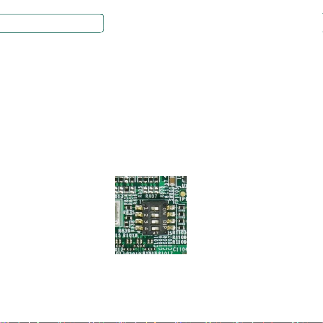
2. Switch SW802 to OFF, ON (from 1-2 bit) to enter serial download mode
as shown in Figure 4.
Figure 4 : SW802 setting for Serial Download Mode
3. Connect the Type-C end of a USB cable into the USB Type-C connector J901.
Connect the other end of the cable to the PC.
Page 15
www.nxp.com
15
4. Connect the plug of the 12V power supply to the DC power jack J902.
Then slide the power switch SW701 to ON. The i.MX 8MQuad will be
enumerated as a HID device on PC.
5. Double click the file *.vbs according to the image type and target device
as shown:
Target Device
Image
VBS file
eMMC
Linux
mfgtool2-yocto-mx8-evk-emmc1.vbs
eMMC
Android
mfgtool2-android-mx8mq-evk-emmc.vbs
MicroSD
Linux
mfgtool2-yocto-mx8-evk-sd2.vbs
MicroSD
Android
mfgtool2-android-mx8mq-evk-sd.vbs
Table 8: Target Device for downloading the image(content may need to be updated)
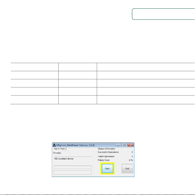
6. For example, we program Linux image, and choose the eMMC as
target device. Double click mfgtool2-yocto-mx8-evk-emmc1.vbs(content
may need to be updated), and then click “Start” to start downloading
images.
Figure 5 : Starting Download
Page 16

Quick Start Guide
16
The process bar becomes green once the download is complete.
Figure 6 : Download Complete
7. Click “Stop”, then “Exit”.
Page 17

www.nxp.com
17
Bootup the board
Before power up, Switch SW802 to ON, OFF (from 1-2 bit) to enter internal boot mode as
shown in Figure 4.
The default output device is HDMI, resolution is 3840x2160p60, if user use a different
display resolution, then need change the resolution setting in the boot args according to
table 7, for example, set 1080p60,
setenv mmcargs 'setenv bootargs console=${console} root=${mmcroot} video=HDMI-A-
1:1920x1080-32@60'
Resolution
Uboot Setting
HDMI 1.4 3840x2160p60
default display mode
HDMI 1.4 3840x2160p30
support by adding: video=HDMI-A-1:3840x2160-
32@30 to bootargs
HDMI 1.4 1920x1080p60
support by adding: video=HDMI-A-1:1920x1080-
32@60 to bootargs
HDMI 1.4 1280x720p60
support by adding: video=HDMI-A-1:1280x720-
32@60 to bootargs
HDMI 1.4 720x480p60
support by adding: video=HDMI-A-1:720x480-
32@60 to bootargs
Table 9: Resolution Setting
After power up, the serial port will output message, when the following message output,
enter ‘root’ and return, the system will success bootup.
Page 18

Quick Start Guide
18
NXP i.MX Release Distro 4.9.51-mx8-beta imx8mqevk ttymxc0
imx8mqevk login:root
root@imx8mqevk:~#
Page 19

www.nxp.com
19
Multimedia
i.MX provides audio optimized software codecs, parsers, hardware acceleration units, and
associated plugins. The i.MX provides GStreamer plugins to access the i.MX multimedia
libraries and hardware acceleration units.
There are three ways to play video and audio
1. gplay-1.0
gplay-1.0 $filename --audio-sink='alsasink device="hw:X,0"'
The audio default output is audio jack, to route to HDMI need set the HDMI sound card,
X is the sound card number.
User can use aplay command to list all the sound card in system.
aplay -l
2. playbin
gst-launch-1.0 playbin uri=$file video-sink=$video-sink-plugin audio-sink='alsasink
device="hw:X,0"'
3. full gstreamer pipeline
gst-launch-1.0 filesrc location=$file ! $capsfilter ! $demux ! queue !
$video_decoder_plugin ! $video_sink_plugin ! $capsfilter ! $audio_decoder_plugin !
$audiosink
Page 20

Quick Start Guide
20
MIPI-DSI
Except the HDMI, the display can be configured as MIPI-DSI. On EVK board,
it uses MINI-SAS interface J1501, connect MIPI-DSI to HDMI cable for display.
The user can use fsl-imx8mq-evk-dual-display.dtb to replace the original dtb
file to enable the MIPI-DSI.
MIPI-CSI
The default DTB will support the MIPI-CSI on J1502. To enable the camera
on J1503, there need fsl-imx8mq-evk-mipi-csi2.dtb to replace the original DTB
file.
The camera gstreamer commands as following:
gst-launch-1.0 v4l2src ! video/x-raw,width=640,height=480 ! kmssink
gst-launch-1.0 v4l2src ! video/x-raw,width=720,height=480 ! kmssink
gst-launch-1.0 v4l2src ! video/x-raw,width=1280,height=720 ! kmssink
gst-launch-1.0 v4l2src ! video/x-raw,width=1920,height=1080 ! kmssink
gst-launch-1.0 v4l2src ! video/x-raw,width=2592,height=1944 !
kmssink
Page 21

www.nxp.com
21
This device complies with Part 15 of the FCC Rules. Operation is
subject to the following two conditions:
(1) This device may not cause harmful interference, and
(2) This device must accept any interference received, including
interference that may cause undesired operation.
Attention that changes or modification not expressly approved
by the party responsible for compliance could void the user’s
authority to operate the equipment.
Note: This product has been tested and found to comply with
the limits for a Class B digital device, pursuant to Part 15 of the
FCC Rules. These limits are designed to provide reasonable
protection against harmful interference in a residential
installation. This product generates, uses, and can radiate radio
frequency energy and, if not installed and used in accordance
with the instructions, may cause harmful interference to radio
communications. However, there is no guarantee that
interference will not occur in a particular installation. If this
product does cause harmful interference to radio or television
reception, which can be determined by turning the equipment
off and on, the user is encouraged to try to correct the
interference by one or more of the following measures:
—Reorient or relocate the receiving antenna.
—Increase the separation between the equipment and receiver.
—Connect the equipment into an outlet on a circuit different
from that to which the receiver is connected.
—Consult the dealer or an experienced radio/TV technician for
help.
This equipment should be installed and operated with a
minimum distance 20cm between the radiator and your body
Page 22

Quick Start Guide
SUPPORT
Visit the i.MX community at
www.imxcommunity.org.
WARRANTY
Visit www.nxp.com/warranty for
complete warranty information.
www.nxp.com/iMX8MQEVK
NXP and the NXP logo are tra demarks of NXP B.V. All other product or service names are the property of
their respective owners. ARM and Cortex are registered tra demarks of ARM Limited (or its subsidiaries) in
the EU and/or elsewhere. All rights reserved. © 2012, 2014–2016 NXP B.V.
Doc Number: IMX8MQUADQSG REV 1
Agile Number: 926-29683 REV A
 Loading...