

Page 1
Quick Start Guide
SABRE Board for Smart Devices
Based on the i.MX 7Dual Applications Processor
SMART APPLICATION BLUEPRINT FOR
RAPID ENGINEERING (SABRE)
Page 2
2
GET TO KNOW SABRE BOARD FOR SMART DEVICES BASED ON
THE i.MX 7DUAL
J1–5 V
DC Power
Connector
J12–JTAG
Connector
SW1–Power
Switch
J11-Debug
UART via USB
J32, J33–mikroBus™
Socket
J18–Smart
Card Interface
J7–SIM Card Slot
U10–eMMC
Expansion
J10–Wi-Fi
®
Antenna
Connection
J17–Speaker Out
J16–Microphone
J15–Headphone
J19–CAN Port
J25–
OTG
J26–
USB
1 GigE
Ethernet
1 GigEJ9–
HDMI
J29–MIPI-CSI
Connectors
SW3-Boot
Configuration
Switches
J13–EPD
Controller
D1
–
Power
on LED
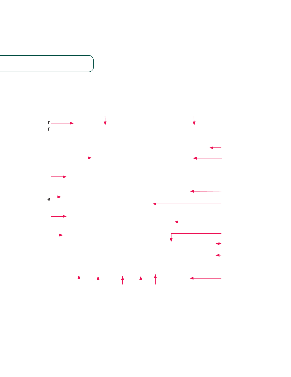
Figure 1. Top View of the i.MX 7Dual SABRE board
Page 3
www.nxp.com
3
J8–Mini-
PCIe
®
Socket
J6–SD
Card Socket
J30–MIPIDSI Display
U12-NAND
expansion
U11–64 MB
QSPI Flash
J14–Parallel
LCD Display
J3–Coin Battery
backup for SNVS
(Secure Nonvolatile
Storage)
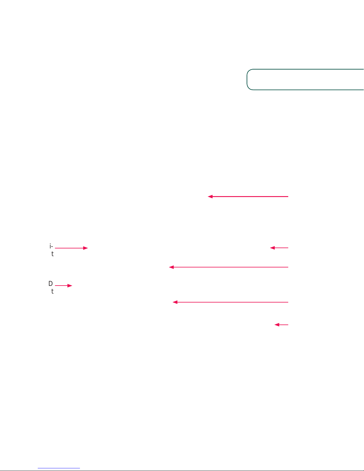
Figure 2. Bottom View of the i.MX 7Dual SABRE board
Page 4

4
The Smart Application Blueprint for
Rapid Engineering (SABRE) board for
smart devices introduces developers
to NXP’s new heterogenous multiprocessing solution: the i.MX 7Dual
applications processor with two ARM®
Cortex®-A7 cores and a single ARM
Cortex-M4 core.
The development kit provides an
out-of-box working demonstration to
power-on and run an operating system
from an SD card, exercising the features
on the SABRE board. SABRE design
information, including documentation
and hardware schematics, is available
at www.nxp.com/iMX7DSABRE.
Software board support packages (BSP)
for Linux® and Android™ reference
links are provided at www.nxp.com/
iMXtools.
GET TO KNOW SABRE BOARD FOR SMART DEVICES BASED ON
THE i.MX 7DUAL PROCESSOR
Page 5

www.nxp.com
5
FEATURES
The following features are available with the i.MX 7Dual SABRE board for smart devices:
• i.MX 7Dual applications processor
- Two ARM
Cortex-A7 cores
operating up to 1 GHz
- Single ARM
Cortex -M4 core
operating up to 200 MHz
• Onboard memory and expansion:
- 1 GB DDR3, 533 MHz
- eMMC expansion footprint
- NAND flash expansion footprint
- QSPI flash expansion footprint
• Power management
- PF3000 PMIC
• Display/Camera connectors
- Expansion port for EPDC
(Electrophoretic display controller)
- Port for Parallel LCD display
- Port for HDMI display
- Port for MIPI DSI display
- Port for MIPI CSI CMOS sensor
(camera)
• Wireless
- 802.11 a/b/g/n/ac Wi-Fi on board
- Bluetooth
®
V4.0 + EDR on board
• Audio CODEC
• Connectivity
- Dual 1 Gigabit Ethernet on board
- 1 SD socket for boot code
- 1 mikroBus socket
- 1 USB host connector
- 1 micro USB OTG connector
- Full Mini PCIe socket
- SIM card slot
- CAN (DB-9)
• Debug
- UART via USB port
- 10-pin standard JTAG connector
• Sensor fusion
- Accelerometer, magnetometer,
gyroscope
- Barometer, altimeter
Page 6

STEP-BY-STEP INSTRUCTIONS
This section describes how to use the
SABRE board for smart devices and the
components in the box. This section
also describes the PC requirements to
develop applications using the SABRE
board for smart devices.
Item Description
Board
i.MX 7Dual SABRE board
for smart devices
Power Supply
100/240 V input, 5 V/5 A
output W/AC adapter
Cable
USB cable (micro-B to
standard-A)
Documentation
Quick Start Guide (this
document)
SD Card
Bootable Linux operating
system demonstration
image
Table 1: SABRE Board for Smart Devices Based
on i.MX 7Dual Development Kit Contents
DEVELOPMENT KIT CONTENTS
1
Insert
SD Card
Insert the supplied SD card into the SD
card slot (J6).
Note: Pay careful attention to the
microSD connector as it is fragile. Slide
the connector up or down, following the
open and close arrows on the connector
in order to place the microSD card inside
and lock it in place.
2
Verify Boot
Switches
By default, both of the two boot switches
(SW3) are configured to zero position.
With the SD inserted, the board will boot
from the SD card. Without the SD card
inserted, the board will be switched into
serial downloader mode required by
manufacturing tool (MFGTools). If any
other boot source is desired, please
refer to documentation at
www.nxp.com/iMX7DSABRE
Page 7

www.nxp.com
7
3
Connect to
Debug UART
Connect the micro-B end of the supplied
USB cable to Debug UART port (J11)
and the other end of the cable to PC
acting as the host terminal. Once the
PC recognizes the virtual USB to UART
device, it can be seen it in your PC
Device Manager list.
There will be 2 ports automatically
configured. The first port will be the
Cortex-A7 core console/debug serial
port, and the second one will be for the
Cortex-M4 core.
Serial port configuration: 115200
baud, 8 data bits, 1 stop bit, no parity.
Note: The PC needs a driver to enable
a virtual COM port through the PC USB
port.
Please consult www.ftdichip.com/
Documents/InstallGuides.htm to
download the correct driver.
4
Connect User Interface
Devices (Optional)
Connect monitor via the HDMI connector
(J9). To interact with the user interface
displayed on the monitor it may be desirable
to attach a keyboard and/or a mouse.
5
Connect Power
Supply
Connect 5 V power supply into power
jack J1 and set SW1 to the on position.
When power is connected to the smart
device, the board will automatically begin
the boot sequence configured in Step 2.
Page 8

8
BOOT PROCESS FOR LINUX IMAGE
During the boot process, there will be
operating system status information
scrolling on the terminal window of the
host computer (if connected).
When the boot process is complete,
the Yocto Project® operating system will
be displayed on the monitor display
(if connected).
To work from the terminal window on
the host PC, press enter at the terminal
window to get the command prompt.
For the Linux operating system, use
username root without password to log
in. The Linux image will run on ARM
Cortex-A7 cores. For details to run
FreeRTOS™ on ARM Cortex-M4 core,
please visit www.nxp.com/iMXtools.
TIPS AND PRECAUTIONS
Input power voltage is suggested to be
5 V. The over-voltage protection circuit
on board will disconnect the power
supply from the system in case the
supply voltage is higher than 5.5 V. The
user must take into account this is the
maximum voltage that can be plugged
into J1.
Proper ESD precautions should be
used when handling the board.
For more options and board details
including connection for EPD (electronic
paper display) panel, LVDS panel and
antenna, please refer to documentation
at www.nxp.com/iMX7DSABRE
Page 9

9
www.nxp.com
FURTHER DOCUMENTATION
• i.MX 7Dual SABRE Board schematics
• i.MX 7Dual SABRE Board BOM
• i.MX 7Dual SABRE Board gerber files
• i.MX 7Dual SABRE Board reference manual
For complete documentation, please
refer to www.nxp.com/iMX7DSABRE
This device complies with Part 15 of the FCC Rules. Operation is subject to the following two conditions:
(1) this device may not cause harmful interference, and (2) this device must accept any interference received,
including interference that may cause undesired operation.
Changes or modifications not expr
essly approved by the party responsible for compliance could void the
user’s authority to operate the equipment.
This equipment has been tested and found to comply with the limits for a Class B digital device, pursuant to
Part 15 of the FCC Rules. These limits are designed to provide reasonable protection against harmful interference
in a residential installation. This equipment generates, uses and can radiate radio frequency energy and, if not
installed and used in accordance with the instructions, may cause harmful interference to radio communications.
However
, there is no guarantee that interference will not occur in a particular installation.
If this equipment does cause harmful interference to radio or television reception, which can be determined
by turning the equipment off and on, the user is encouraged to try to correct the interference by one or more
of the following measures:
•
Reorient or relocate the receiving antenna.
• Increase the separation between the equipment and receiver.
• Connect the equipment into an outlet on a circuit different from that to which the receiver is connected.
• Consult the dealer or an experienced radio/TV technician for help.
Page 10

Note
1、The grantee is responsible for ensuring through appropriate testing and clear
instructions of use contained in the instruction manual that the host manufactures product
is compliant to all the applicable FCC rules. The installer must to perform tests
inside of each host for the host manufactures product(s) are compliant to all
the applicable FCC rule.
2、This equipment must be installed and operated in accordance with provided
instructions and the antenna(s) used for this transmitter must be installed to
provide a separation distance of at least 20 cm from all persons and must not
be co-located or operating in conjunction with any other antenna or
transmitter. End-users and installers must be provided with antenna
installation instructions and transmitter operating conditions for satisfying
RF exposure compliance.
Page 11

Page 12

SUPPORT
Visit i.MX community at
www.imxcommunity.org.
WARRANTY
Visit www.nxp.com/warranty for
complete warranty information.
www.nxp.com/iMX7DSABRE
NXP and the NXP logo are trademarks of NXP B.V. All other product or service names are the property of their
respective owners. ARM and Cortex are registered trademarks of ARM Limited (or its subsidiaries) in the EU and/
or elsewhere. All rights reserved. © 2016 NXP B.V.
Doc Number: SABRESDBIMX7DUALQSG REV 0
Agile Number: 926-28590 REV A
Get Started
Further design resources
and documentation under
“Jump Start Your Design”
at www.nxp.com/iMX7DSABRE.
 Loading...