

Page 1

MC1322x Simple Media Access
Controller Demonstration
Applications
User's Guide
Document Number: 22xSMACDAUG
Rev. 1.3
09/2011
Page 2

How to Reach Us:
Home Page:
www.freescale.com
E-mail:
support@freescale.com
USA/Europe or Locations Not Listed:
Freescale Semiconductor
Technical Information Center, CH370
1300 N. Alma School Road
Chandler, Arizona 85224
+1-800-521-6274 or +1-480-768-2130
support@freescale.com
Europe, Middle East, and Africa:
Freescale Halbleiter Deutschland GmbH
Technical Information Center
Schatzbogen 7
81829 Muenchen, Germany
+44 1296 380 456 (English)
+46 8 52200080 (English)
+49 89 92103 559 (German)
+33 1 69 35 48 48 (French)
support@freescale.com
Japan:
Freescale Semiconductor Japan Ltd.
Headquarters
ARCO Tower 15F
1-8-1, Shimo-Meguro, Meguro-ku,
Tokyo 153-0064, Japan
0120 191014 or +81 3 5437 9125
support.japan@freescale.com
Asia/Pacific:
Freescale Semiconductor Hong Kong Ltd.
Technical Information Center
2 Dai King Street
Tai Po Industrial Estate
Tai Po, N.T., Hong Kong
+800 2666 8080
support.asia@freescale.com
For Literature Requests Only:
Freescale Semiconductor Literature Distribution Center
P.O. Box 5405
Denver, Colorado 80217
1-800-521-6274 or 303-675-2140
Fax: 303-675-2150
LDCForFreescaleSemiconductor@hibbertgroup.com
Information in this document is provided solely to enable system and software implementers to use
Freescale Semiconductor products. There are no express or implied copyright licenses granted
hereunder to design or fabricate any integrated circuits or integrated circuits based on the information
in this document.
Freescale Semiconductor reserves the right to make changes without further notice to any products
herein. Freescale Semiconductor makes no warranty, representation or guarantee regarding the
suitability of its products for any particular purpose, nor does Freescale Semiconductor assume any
liability arising out of the application or use of any product or circuit, and specifically disclaims any
and all liability, including without limitation consequential or incidental damages. “Typical” parameters
that may be provided in Freescale Semiconductor data sheets and/or specifications can and do vary
in different applications and actual performance may vary over time. All operating parameters,
including “Typicals”, must be validated for each customer application by customer’s technical
experts. Freescale Semiconductor does not convey any license under its patent rights nor the rights
of others. Freescale Semiconductor products are not designed, intended, or authorized for use as
components in systems intended for surgical implant into the body, or other applications intended to
support or sustain life, or for any other application in which the failure of the Freescale Semiconductor
product could create a situation where personal injury or death may occur. Should Buyer purchase
or use Freescale Semiconductor products for any such unintended or unauthorized application,
Buyer shall indemnify and hold Freescale Semiconductor and its officers, employees, subsidiaries,
affiliates, and distributors harmless against all claims, costs, damages, and expenses, and
reasonable attorney fees arising out of, directly or indirectly, any claim of personal injury or death
associated with such unintended or unauthorized use, even if such claim alleges that Freescale
Semiconductor was negligent regarding the design or manufacture of the part.
IAR Systems, IAR Embedded Workbench, C-SPY, visualSTATE, From Idea to Target, IAR KickStart
Kit, IAR PowerPac, IAR YellowSuite, and IAR are trademarks or registered trademarks owned by IAR
Systems AB.
Copyright © 2007 IAR Systems AB.
ARM is the registered trademark of ARM Limited. ARM7TDMI-S is the trademark of ARM Limited.
Freescale™ and the Freescale logo are trademarks of Freescale Semiconductor, Inc. All other
product or service names are the property of their respective owners.
© Freescale Semiconductor, Inc. 2005, 2006, 2007, 2008, 2009, 2010, 2011. All rights reserved.
Page 3

Contents
About This Book. . . . . . . . . . . . . . . . . . . . . . . . . . . . . . . . . . . . . . . . . . . . . . . . . . . . . . . . . . . . . . iii
Available Devices . . . . . . . . . . . . . . . . . . . . . . . . . . . . . . . . . . . . . . . . . . . . . . . . . . . . . . . . . . . . . iii
Audience . . . . . . . . . . . . . . . . . . . . . . . . . . . . . . . . . . . . . . . . . . . . . . . . . . . . . . . . . . . . . . . . . . . . iv
Organization . . . . . . . . . . . . . . . . . . . . . . . . . . . . . . . . . . . . . . . . . . . . . . . . . . . . . . . . . . . . . . . . . iv
Revision History . . . . . . . . . . . . . . . . . . . . . . . . . . . . . . . . . . . . . . . . . . . . . . . . . . . . . . . . . . . . . . . v
Definitions, Acronyms, and Abbreviations . . . . . . . . . . . . . . . . . . . . . . . . . . . . . . . . . . . . . . . . . . v
References. . . . . . . . . . . . . . . . . . . . . . . . . . . . . . . . . . . . . . . . . . . . . . . . . . . . . . . . . . . . . . . . . . . vi
Chapter 1
Generating an SMAC Application and Port Configuration
1.1 Loading Applications Into a Board Using the JTAG J-Link ARM Debugger . . . . . . . . . . . . . . 1-6
1.2 JTAG Debugging . . . . . . . . . . . . . . . . . . . . . . . . . . . . . . . . . . . . . . . . . . . . . . . . . . . . . . . . . . . . 1-7
1.3 UART/USB Virtual COM Port Setup . . . . . . . . . . . . . . . . . . . . . . . . . . . . . . . . . . . . . . . . . . . . 1-9
Chapter 2
Wireless UART Demonstration
2.1 Generating a Project From BeeKit . . . . . . . . . . . . . . . . . . . . . . . . . . . . . . . . . . . . . . . . . . . . . . . 2-1
2.2 Open, Compile and Execute the Wireless UART. . . . . . . . . . . . . . . . . . . . . . . . . . . . . . . . . . . . 2-2
Chapter 3
Connectivity Test
3.1 Loading the Connectivity Application . . . . . . . . . . . . . . . . . . . . . . . . . . . . . . . . . . . . . . . . . . . . 3-2
3.2 UART/USB Virtual Com Port Setup . . . . . . . . . . . . . . . . . . . . . . . . . . . . . . . . . . . . . . . . . . . . . 3-3
3.3 Starting the Connectivity Test . . . . . . . . . . . . . . . . . . . . . . . . . . . . . . . . . . . . . . . . . . . . . . . . . . 3-4
3.4 Connectivity Test Applications . . . . . . . . . . . . . . . . . . . . . . . . . . . . . . . . . . . . . . . . . . . . . . . . . 3-5
3.4.1 Test Mode Application . . . . . . . . . . . . . . . . . . . . . . . . . . . . . . . . . . . . . . . . . . . . . . . . . . . . . 3-6
3.4.2 Spectrum Analyzer Captures . . . . . . . . . . . . . . . . . . . . . . . . . . . . . . . . . . . . . . . . . . . . . . . . 3-7
3.5 Packet Error Rate (PER) Test . . . . . . . . . . . . . . . . . . . . . . . . . . . . . . . . . . . . . . . . . . . . . . . . . . 3-10
3.5.1 Starting the PER Test . . . . . . . . . . . . . . . . . . . . . . . . . . . . . . . . . . . . . . . . . . . . . . . . . . . . . 3-10
3.5.2 PER operation . . . . . . . . . . . . . . . . . . . . . . . . . . . . . . . . . . . . . . . . . . . . . . . . . . . . . . . . . . . 3-11
3.6 Range Test . . . . . . . . . . . . . . . . . . . . . . . . . . . . . . . . . . . . . . . . . . . . . . . . . . . . . . . . . . . . . . . . 3-12
3.7 Crystal Adjustment . . . . . . . . . . . . . . . . . . . . . . . . . . . . . . . . . . . . . . . . . . . . . . . . . . . . . . . . . . 3-13
Chapter 4
Accelerometer Demonstration
4.1 Loading the Accelerometer Application. . . . . . . . . . . . . . . . . . . . . . . . . . . . . . . . . . . . . . . . . . . 4-1
4.2 Board Setup. . . . . . . . . . . . . . . . . . . . . . . . . . . . . . . . . . . . . . . . . . . . . . . . . . . . . . . . . . . . . . . . . 4-1
4.3 Board One Setup (PC_Radio Board) . . . . . . . . . . . . . . . . . . . . . . . . . . . . . . . . . . . . . . . . . . . . . 4-1
4.4 Board Two Setup (Accelerometer Board) . . . . . . . . . . . . . . . . . . . . . . . . . . . . . . . . . . . . . . . . . 4-1
4.5 PC Setup . . . . . . . . . . . . . . . . . . . . . . . . . . . . . . . . . . . . . . . . . . . . . . . . . . . . . . . . . . . . . . . . . . . 4-2
4.6 Verifying Operation . . . . . . . . . . . . . . . . . . . . . . . . . . . . . . . . . . . . . . . . . . . . . . . . . . . . . . . . . . 4-3
4.7 Setting Up the Calibration Application . . . . . . . . . . . . . . . . . . . . . . . . . . . . . . . . . . . . . . . . . . . 4-6
MC1322x SMAC Demonstration Application User’s Guide, Rev. 1.3
Freescale Semiconductor i
Page 4

Chapter 5
Low Power Bell Demonstration
5.1 Generating the Project From BeeKit . . . . . . . . . . . . . . . . . . . . . . . . . . . . . . . . . . . . . . . . . . . . . 5-1
5.2 Open, Compile and Execute the Low Power Bell Application . . . . . . . . . . . . . . . . . . . . . . . . . 5-1
Chapter 6
Generic Application Demonstration
6.1 Generating a Project From BeeKit . . . . . . . . . . . . . . . . . . . . . . . . . . . . . . . . . . . . . . . . . . . . . . . 6-1
6.2 Open, Compile and Execute the Generic Application . . . . . . . . . . . . . . . . . . . . . . . . . . . . . . . . 6-1
Chapter 7
Simple ZigBee Test Client (SZTC) Demonstration
7.1 Generating a Project From BeeKit . . . . . . . . . . . . . . . . . . . . . . . . . . . . . . . . . . . . . . . . . . . . . . . 7-1
7.2 Testing the SZTC with the WirelessUART . . . . . . . . . . . . . . . . . . . . . . . . . . . . . . . . . . . . . . . . 7-1
Chapter 8
Repeater Demonstration
8.1 Generating a Project From BeeKit . . . . . . . . . . . . . . . . . . . . . . . . . . . . . . . . . . . . . . . . . . . . . . . 8-1
8.2 Open, Compile and Execute the Repeater . . . . . . . . . . . . . . . . . . . . . . . . . . . . . . . . . . . . . . . . . 8-2
8.3 Repeater Menu, Configuration and Settings. . . . . . . . . . . . . . . . . . . . . . . . . . . . . . . . . . . . . . . . 8-5
8.4 Running the Repeater Demonstration. . . . . . . . . . . . . . . . . . . . . . . . . . . . . . . . . . . . . . . . . . . . . 8-7
8.4.1 Creating a Sniffer . . . . . . . . . . . . . . . . . . . . . . . . . . . . . . . . . . . . . . . . . . . . . . . . . . . . . . . . . 8-7
8.4.2 Running a Dummy Repeater. . . . . . . . . . . . . . . . . . . . . . . . . . . . . . . . . . . . . . . . . . . . . . . . . 8-7
Chapter 9
Weather Station Demonstration
9.1 Generating a Project From BeeKit . . . . . . . . . . . . . . . . . . . . . . . . . . . . . . . . . . . . . . . . . . . . . . . 9-1
9.2 Open, Compile, and Load the Weather Station . . . . . . . . . . . . . . . . . . . . . . . . . . . . . . . . . . . . . 9-3
9.3 Weather Station PC Application. . . . . . . . . . . . . . . . . . . . . . . . . . . . . . . . . . . . . . . . . . . . . . . . . 9-5
9.3.1 Features. . . . . . . . . . . . . . . . . . . . . . . . . . . . . . . . . . . . . . . . . . . . . . . . . . . . . . . . . . . . . . . . . 9-5
9.3.2 Connecting to a Network Node . . . . . . . . . . . . . . . . . . . . . . . . . . . . . . . . . . . . . . . . . . . . . . 9-6
9.3.3 Data Packet Structure . . . . . . . . . . . . . . . . . . . . . . . . . . . . . . . . . . . . . . . . . . . . . . . . . . . . . . 9-8
9.3.4 Loading a Pre-existing Log File . . . . . . . . . . . . . . . . . . . . . . . . . . . . . . . . . . . . . . . . . . . . . . 9-8
Chapter 10
Over The Air Programmer Demonstration
10.1 Generating a Project From BeeKit . . . . . . . . . . . . . . . . . . . . . . . . . . . . . . . . . . . . . . . . . . . . . . 10-2
10.2 Open, Compile, and Load the OTAP Programmer. . . . . . . . . . . . . . . . . . . . . . . . . . . . . . . . . . 10-2
10.3 Downloading an OTAP-enabled Image to the OTAP Programmer Board. . . . . . . . . . . . . . . . 10-4
10.4 Downloading an OTAP-enabled Application. . . . . . . . . . . . . . . . . . . . . . . . . . . . . . . . . . . . . . 10-6
10.5 Transmitting the New Image to the OTAP-enabled Board . . . . . . . . . . . . . . . . . . . . . . . . . . . 10-9
MC1322x SMAC Demonstration Application User’s Guide, Rev. 1.3
ii Freescale Semiconductor
Page 5

10.5.1 Using the Serial Interface . . . . . . . . . . . . . . . . . . . . . . . . . . . . . . . . . . . . . . . . . . . . . . . . . . 10-9
10.5.2 Using The LCD Interface . . . . . . . . . . . . . . . . . . . . . . . . . . . . . . . . . . . . . . . . . . . . . . . . . 10-11
10.6 Verifying the Transmitted Image . . . . . . . . . . . . . . . . . . . . . . . . . . . . . . . . . . . . . . . . . . . . . . 10-12
MC1322x SMAC Demonstration Application User’s Guide, Rev. 1.3
Freescale Semiconductor iii
Page 6

MC1322x SMAC Demonstration Application User’s Guide, Rev. 1.3
iv Freescale Semiconductor
Page 7

About This Book
This guide provides a detailed description of the MC1322x Simple Media Access Controller (MC1322x
SMAC) demonstration applications. The demonstration applications are delivered as ANSI C source code
and are included in the MC1322x SMAC Codebase. The Codebase is incorporated into the Freescale
BeeKit Wireless Connectivity Toolkit. See the BeeKit Wireless Connectivity Toolkit User’s Guide
(BKWCTKUG) and the BeeKit on-line help for more information.
This guide explains how to run various MC1322x SMAC demonstration applications and provides
information that allows users to more easily take advantage of these demonstration applications or modify
the applications to fit their specific needs.
The demonstration applications shown in this guide are compatible with previous SMAC demonstrations
at the protocol level. However, the applications that employ security will be different because the
MC1322x SMAC takes advantage of the Advanced Security Module (ASM, AES based) security module
included in the MC122x Platform in a Package (PiP). The MC1322x device provides a more robust
security approach. For more information about security and the MC1322x, see the appropriate MC1322x
documentation available at www.freescale.com/zigbee.
The MC1322x SMAC API is similar to previous SMAC APIs. For more detail about the APIs, see the
MC1322x Simple Media Access Controller (SMAC) Reference Manual (22xSMACRM).
Available Devices
The MC1322x family is available as two part numbers. These device types differ only in their ROM
contents, all other device hardware, performance, and specifications are identical:
• MC13224V - this is the original version and is the generic part type.
— The MC13224V is intended for most IEEE 802.15.4 applications including MAC-based,
ZigBee-2007 Profile 1, and ZigBee RF4CE targets.
— It has a more complete set of peripheral drivers in ROM.
• MC13226V - this is a more recent version and is provided specifically for ZigBee-2007 Profile 2
(Pro) applications. Only the onboard ROM image has been changed to optimize ROM usage for
the ZigBee Pro profile and maximize the amount of available RAM for application use.
— The IEEE MAC/PHY functionality has been streamlined to include only that functionality
required by the ZigBee specification. The MAC functionality is 802.15.4 compatible.
— For a typical application, up to 20 kbytes more of RAM is available versus the M13224V
— Some drivers present in the MC13224 ROM have been removed and these include the ADC,
LCDfont, and SSI drivers. These drivers are still available as library functions, but now
compile into the RAM space.
— The Low Level Component (LLC) functionality has also been streamlined for the ZigBee
specification
NOTE
• When running the Freescale IEEE 802.15.4 MAC (or a related stack) on
the MC1322x platform, neither beaconing or GTS are supported.
MC1322x SMAC Demonstration Application User’s Guide, Rev. 1.3
Freescale Semiconductor iii
Page 8

• See the MC1322x Reference Manual (Document No MC1322xRM), for
information on using applications on these devices.
Audience
This document is intended for application developers generating MC1322x SMAC demonstration
applications from the Freescale BeeKit Wireless Connectivity Toolkit or modifying these applications as
a starting point for proprietary applications.
Organization
This document is organized into ten chapters.
Chapter 1 Introduction — This chapter shows how to generate an SMAC demonstration
application using BeeKit.
Chapter 2 Wireless UART — Provides a detailed description of MC1322x SMAC Wireless
UART demonstration application.
Chapter 3 Connectivity Test — Provides an easy way to test the RF performance of the
transceiver for basic transmitter and receiver tests. It includes test mode
(continuous tx, modulated, unmodulated, etc.); Packet Error Rate and Range (LQI
measurements).
Chapter 4 Accelerometer Test — Provides an overview of the Accelerometer
Demonstration application, which shows various uses for the Freescale X, Y, and
Z axes accelerometers.
Chapter 5 Low Power Bell — Shows how to implement different low power options.
Chapter 6 Generic Application — Provides a start template for users what want to add their
own application.
Chapter 7 Simple ZTC — Allows users to test the SMAC primitives by sending special data
frames through the Serial/USB port.
Chapter 8 Repeater— Implements a simple repeater which extends the range between two
boards running an SMAC application demonstration.
Chapter 9 Weather Station— Simulates a Weather Station and shows the use of Freescale
sensors for acceleration and pressure.
Chapter 10 Over The Air Programmer (OTAP) — Allows users to update a board’s FLASH
remotely without a physical connection. Given an OTAP enabled application and
an OTAP programmer, users can replace an existing application with a new
application.
MC1322x SMAC Demonstration Application User’s Guide, Rev. 1.3
iv Freescale Semiconductor
Page 9

Revision History
The following table summarizes revisions to this document since the previous release (Rev. 1.2).
Revision History
Location Revision
Chapters 3 and 6 Various software updates.
Definitions, Acronyms, and Abbreviations
The following list defines the acronyms and abbreviations used in this document.
AES Advanced Encryption Standard
API Application Program Interface
ASM Advanced Security Module
BDM Background Debug Module
BDM debugger A debugger using the BDM interface for communication with the MCU. An
example is the P&E BDM Multilink debugger for HCS08.
CBC Cipher Block Chaining.
CBC-MAC Cipher Block Chaining Message Authentication Code.
CCM Counter with CBC-MAC
CTR Counter.
dBm Decibels referred to one milliwatt.
ED Energy Detect.
EN End Node - Evaluation Board.
EVB Evaluation Boards.
EVK Evaluation Kit
EWW Embedded Workbench IDE work space file
GUI Graphical User Interface
IDE Integrated Development Environment
LP Low Power
MAC Media Access Control
MAC Message Authentication Code
MCU MicroController Unit
NCB Network Coordinator Board
NVM None-Volatile Memory
OTAP Over The Air Programming
PC Personal Computer
PCB Printed Circuit Board
MC1322x SMAC Demonstration Application User’s Guide, Rev. 1.3
Freescale Semiconductor v
Page 10

PiP Platform in Package
RX Reception
S19 S - Record. 'S19' is the file extension used for the Freescale binary image format.
The S19 file encapsulates the binary image as a list of ASCII records. Each record
contains a length -, address -, data - and checksum field. The 16 bit address field
allows a memory space for up to 64 KB. The S19 can be generated with
CodeWarrior IDE and is the product from the linking process. S19 does not
contain additional information to a debugger (where to look for source files).
Safe Mode Boot The Embedded Bootloader boots up using safe default system values.
SMAC Simple Media Access Control.
SN Sensor Node Evaluation Board.
TX Transmission.
References
The following sources were referenced to produce this book:
[1] Freescale 802.15.4 MAC/PHY Software Reference Manual (802154MPSRM)
[2] Freescale MC1322x Simple Media Access Controller (SMAC) Reference Manual (22xSMACRM)
MC1322x SMAC Demonstration Application User’s Guide, Rev. 1.3
vi Freescale Semiconductor
Page 11
Chapter 1
Generating an SMAC Application and Port Configuration
This chapter provides an overview of how to generate an SMAC demonstration application using BeeKit.
This chapter only provides an overview of how to generate an SMAC demonstration application. For more
details on installing BeeKit and BeeKit operation, see the BeeKit Wireless Connectivity Toolkit User’s
Guide (BKWCTKUG).
This chapter also shows how to set up a virtual UART/USB COM port. Once the ports are configured, refer
to the appropriate application chapter in this guide.
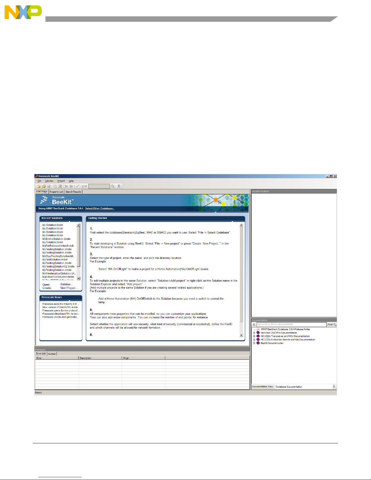
1. Install and then launch BeeKit and the BeeKit main window appears as shown in Figure 1-1.
Figure 1-1. BeeKit Graphical User Interface
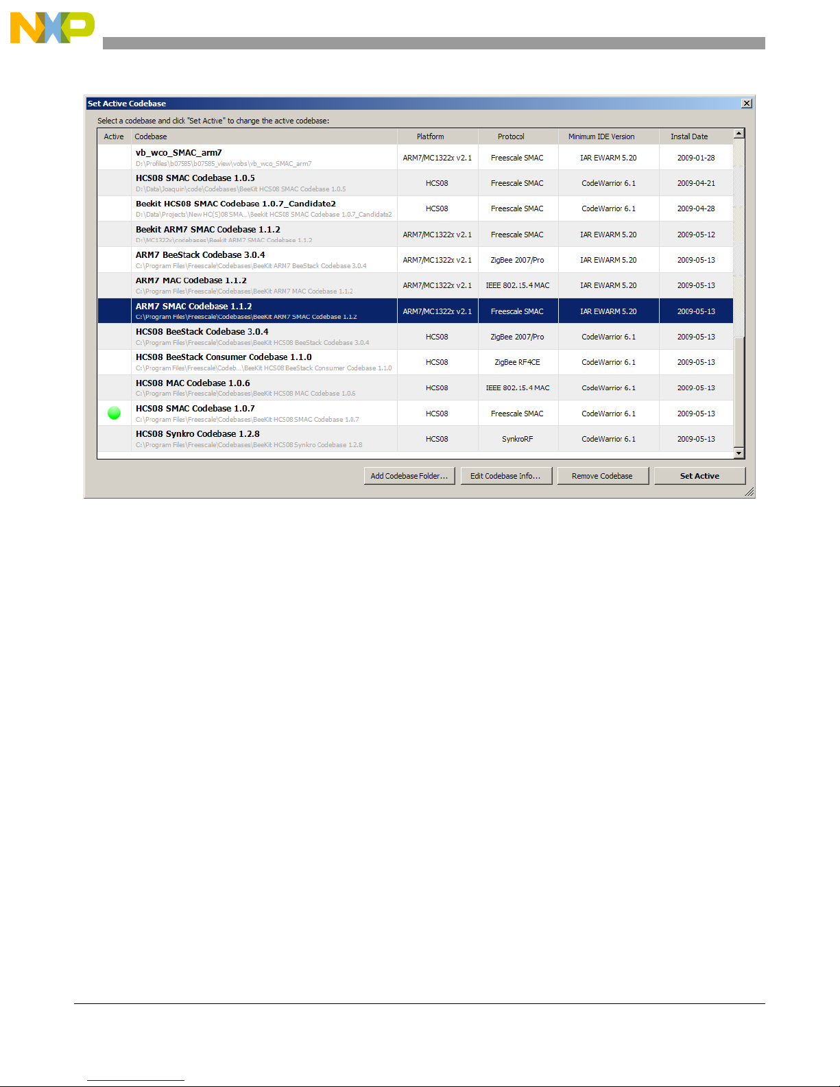
2. Select the SMAC Codebase as shown in Figure 1-2.
MC1322x SMAC Demonstration Application User’s Guide, Rev. 1.3
Freescale Semiconductor 1-1
Page 12
Generating an SMAC Application and Port Configuration
Figure 1-2. selecting SMAC Codebase
In BeeKit, a Codebase is a set of files and rules that permit users to generate the final applications. This
step is important, because the SMAC Codebase is different than the Codebase of MAC and BeeStack.
MC1322x SMAC Demonstration Application User’s Guide, Rev. 1.3
1-2 Freescale Semiconductor
Page 13
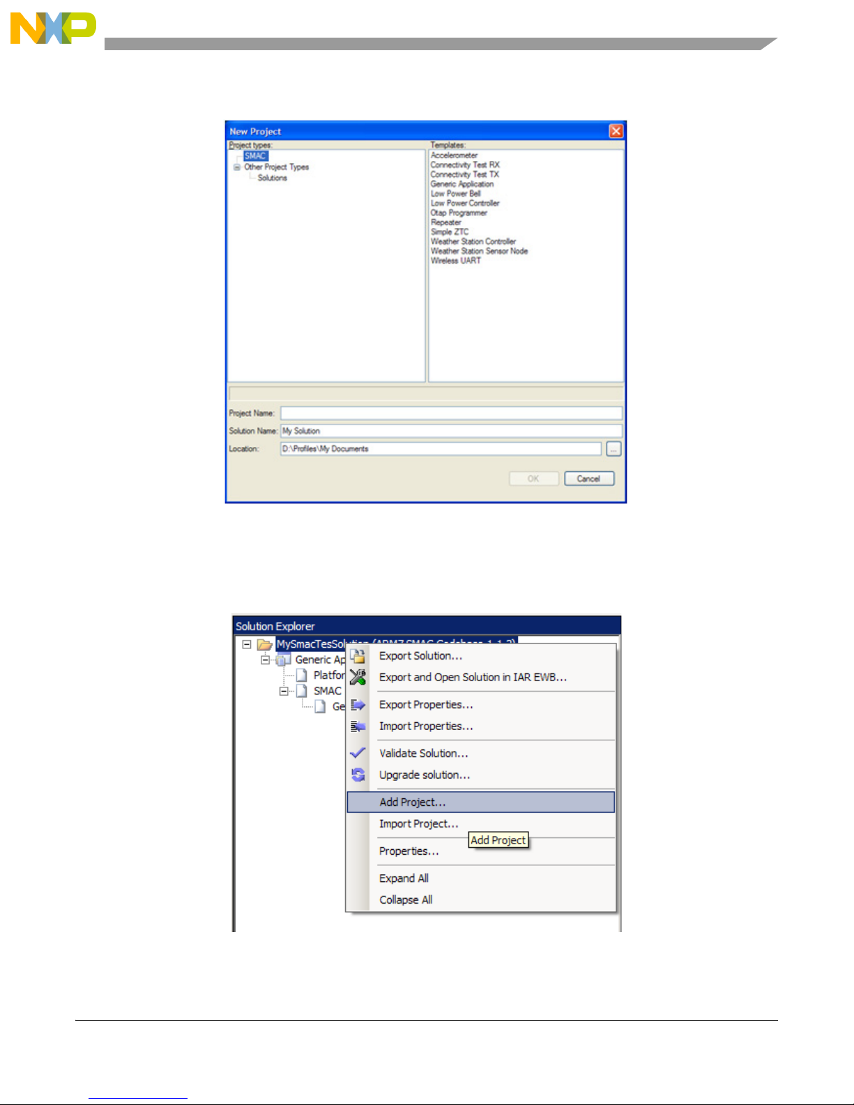
3. Create a new project as shown in Figure 1-3.
Generating an SMAC Application and Port Configuration
Figure 1-3. Creating a new project
If users create a new project and there is not a an existing solution, then users are also creating a solution.
The solution must have a name. Specify a name for the solution.
4. Add other required projects for the evaluation as shown in Figure 1-4.
Figure 1-4. Adding a New Project to a Existing Solution
MC1322x SMAC Demonstration Application User’s Guide, Rev. 1.3
Freescale Semiconductor 1-3
Page 14

Generating an SMAC Application and Port Configuration
5. Modify the project properties as shown in Table 1-1.
Tab l e 1-1. Software Component Properties
Component Property Description
Security Enabled Enables the security Module to automatically encrypt the
information sent and received.
Promiscuous Mode If set to true, the SMAC Code Bytes are not sent prior to the
message.
Security Type This is the security engine used if the security enabled property
is true.
Security Default KEY0 Less Significative 32 bit Word of the 128 bits to be used as key
on the ciphering engine.
Security Default KEY1 Second Significative 32 bit Word of the 128 bits to be used as
key on the ciphering engine.
SMAC
PLM
Security Default KEY2 Third Significative 32 bit Word of the 128 bits to be used as key
on the ciphering engine.
Security Default KEY3 More Significative 32 bit Word of the 128 bits to be used as key
on the ciphering engine.
Security Default COUNTER0 Less Significative 32 bit Word of the 128 bits to be used as initial
counter on the ciphering engine.
Security Default COUNTER1 Second Significative 32 bit Word of the 128 bits to be used as
initial counter on the ciphering engine.
Security Default COUNTER2 Third Significative 32 bit Word of the 128 bits to be used as
initial counter on the ciphering engine.
Security Default COUNTER3 More Significative 32 bit Word of the 128 bits to be used as
initial counter on the ciphering engine.
Target hardware Allows board selection.
LCD Enabled Includes support for LCDs.
Default SCI Port Selects the SCI port. Freescale ZigBee boards usually have
SCI Port 1 connected to a DB9 connector and SCI port 2
connected to a USB connector.
MCU Version Can select either MC13224 or MC13226.
Default Channel Default starting channel in the application.
Output Power Initial power output configuration.
Baud Rate Baud rate to be set at the default SCI port for this application
App
1-4 Freescale Semiconductor
OTAP Enabled Enables the OTAP Module to allow over the air programming of
OTAP Request Code If the OTAP Module is enabled the application will switch to
OTAP Device Id This ID distinguishes between different devices identified by an
MC1322x SMAC Demonstration Application User’s Guide, Rev. 1.3
the application.
OTAP mode when this OTAP Request Code is received.
OTAP Programmer.
Page 15
Generating an SMAC Application and Port Configuration
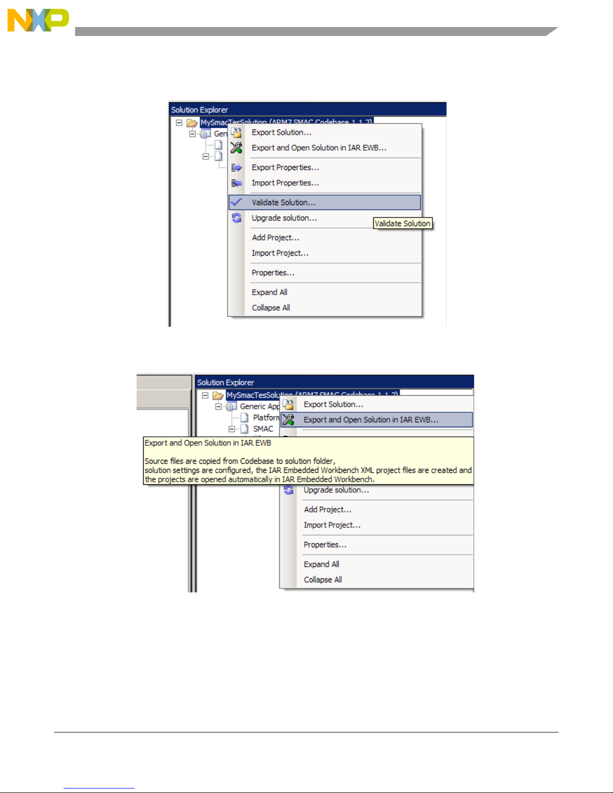
6. Users must now validate the solution as shown in Figure 1-5. The validation process helps users
find possible inconsistencies between the selected hardware and properties.
Figure 1-5. Validating a Solution
7. Users must now export the solution as shown in Figure 1-6.
Figure 1-6. Exporting a Solution
MC1322x SMAC Demonstration Application User’s Guide, Rev. 1.3
Freescale Semiconductor 1-5
Page 16

Generating an SMAC Application and Port Configuration
1.1 Loading Applications Into a Board Using the JTAG J-Link ARM
Debugger
After exporting from BeeKit, the projects are generated as a .eww file. Perform the following tasks to load
the application to a board, using the IAR Embedded Workbench IDE. This example uses the repeater
application.
1. As shown in Figure 1-7, open the My Solution.eww file.
Figure 1-7. Opening a project
2. Make the project by clicking the Make button (Figure 1-8) which is located at the top of the IAR
Embedded Workbench main Window as shown in Figure 1-9.
Figure 1-8. Make Button
Figure 1-9. IAR Embedded Workbench Main Window
3. Connect the J-Link to the target board.
4. Click the Debug button Figure 1-10 which is located at the top of the IAR Embedded Workbench
main window as shown in Figure 1-9.
MC1322x SMAC Demonstration Application User’s Guide, Rev. 1.3
1-6 Freescale Semiconductor
Figure 1-10. Debug
Page 17
Generating an SMAC Application and Port Configuration
5. The application will start to download, to run the application press F5 key or click the Go button
Figure 1-11
Figure 1-11. Go
1.2 JTAG Debugging
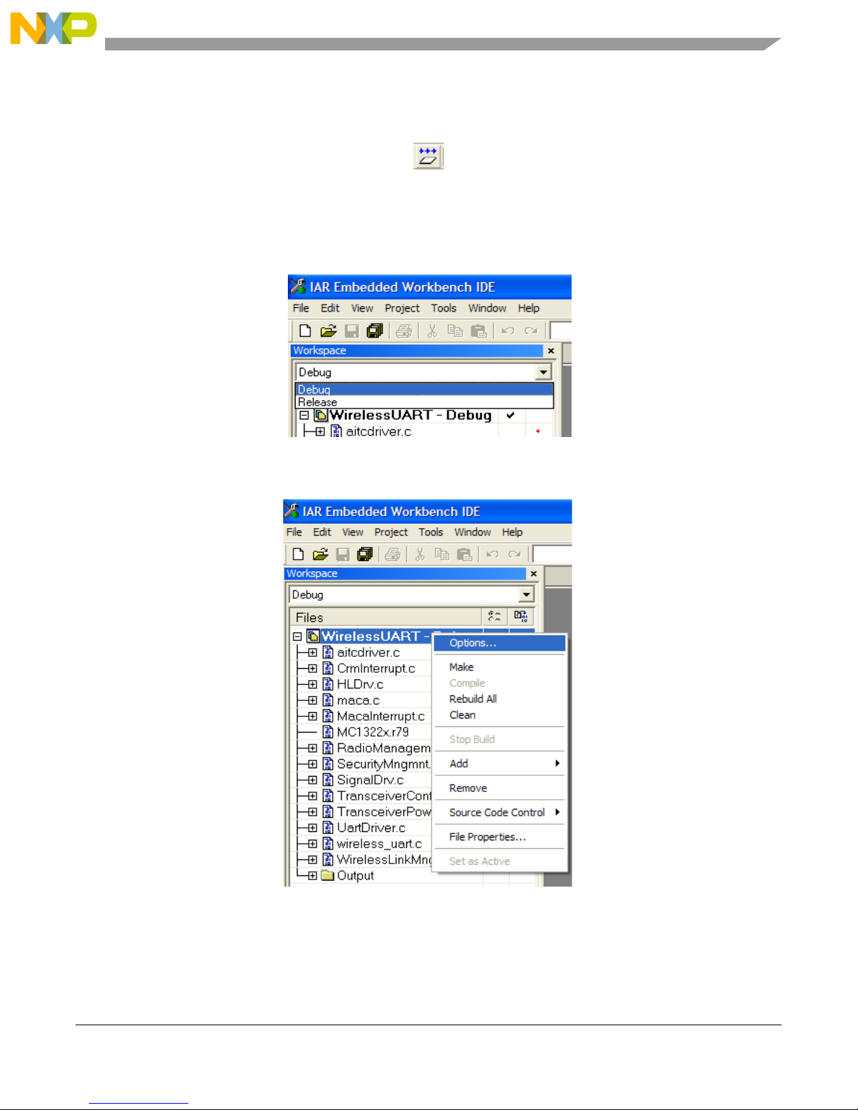
1. To debug an application select “Debug“ at the Work space window as shown in Figure 1-12.
Figure 1-12. IAR Embedded Workbench Work Space Debug and Release Window
2. Right click on the project name and select “Options“ as shown in Figure 1-13.
Figure 1-13. IAR Embedded Workbench Options Menu
3. At the debugger category on the Setup tab, select the “J-Link/J-Trace“ option as shown in
Figure 1-14.
MC1322x SMAC Demonstration Application User’s Guide, Rev. 1.3
Freescale Semiconductor 1-7
Page 18
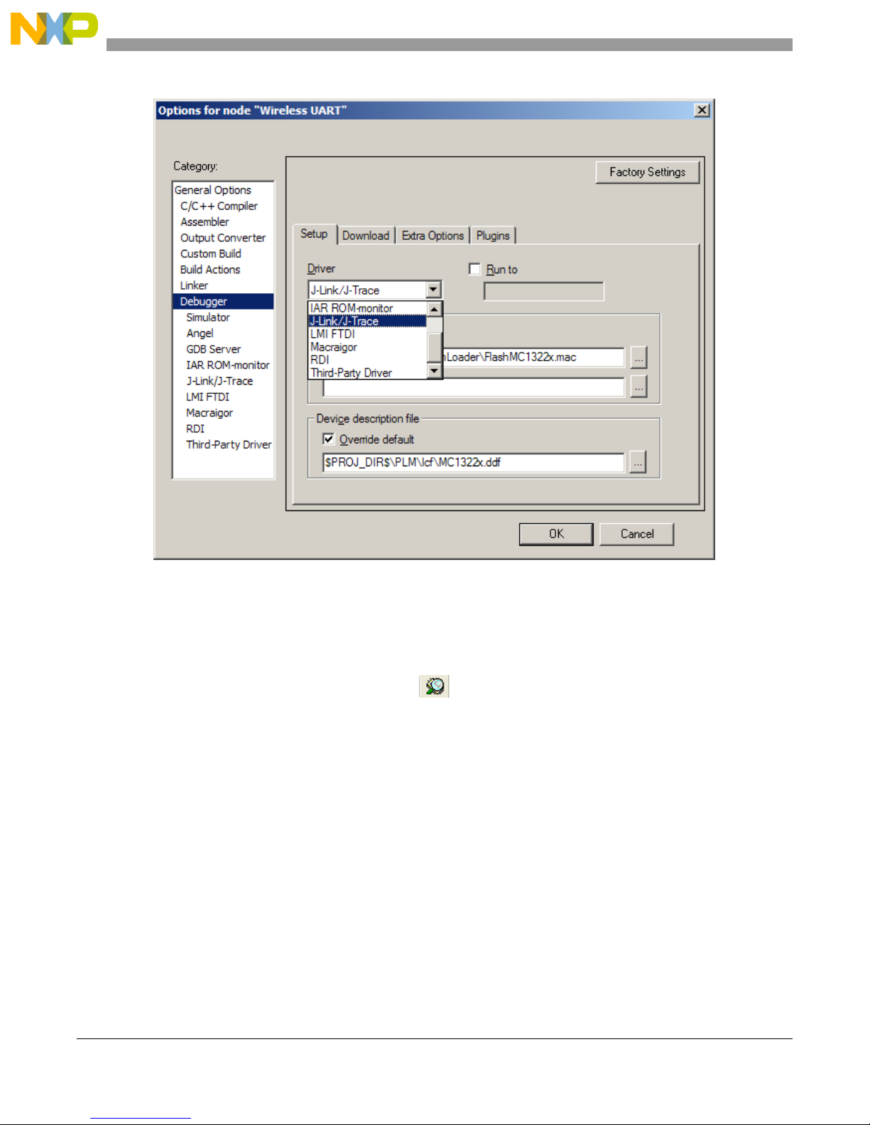
Generating an SMAC Application and Port Configuration
Figure 1-14. Debugger Setup
4. Ensure that the JTAG Debugger is connected to the PC and to the board.
5. On the Project window press the [CTRL]+[D] keys or just click the debug button shown in
Figure 1-15 to begin the debugging session.
Figure 1-15. Debug Button
MC1322x SMAC Demonstration Application User’s Guide, Rev. 1.3
1-8 Freescale Semiconductor
Page 19
Generating an SMAC Application and Port Configuration
1.3 UART/USB Virtual COM Port Setup
This section describes how to set up a virtual COM port for the following demonstration applications:
• Chapter 2, “Wireless UART Demonstration”
• Chapter 3, “Connectivity Test”
• Chapter 6, “Generic Application Demonstration”
• Chapter 7, “Simple ZigBee Test Client (SZTC) Demonstration”
• Chapter 8, “Repeater Demonstration”
• Chapter 9, “Weather Station Demonstration”
• Chapter 10, “Over The Air Programmer Demonstration”
Attach two boards to two PCs. This allows communication using a PC terminal communications program.
The two boards can be attached to two different serial ports of the same PC if needed, but Freescale
recommends using two PCs when possible.
1. Connect each of the boards to a separate PC either with an RS-232 cable or a USB cable. If using
a USB cable, a corresponding USB driver is required. Freescale recommends a direct USB
connection. Do not use a USB hub. This driver is located in the following directory:
<INSTALL DIR>\Freescale\Drivers
The BeeKit CD image is available from the Freescale ZigBee web site at
www.freescale.com/zigbee.
2. To check which COM port is being used by the USB, do the following:
a) Open the Windows System Properties window using Start->Settings->Control Panel->System.
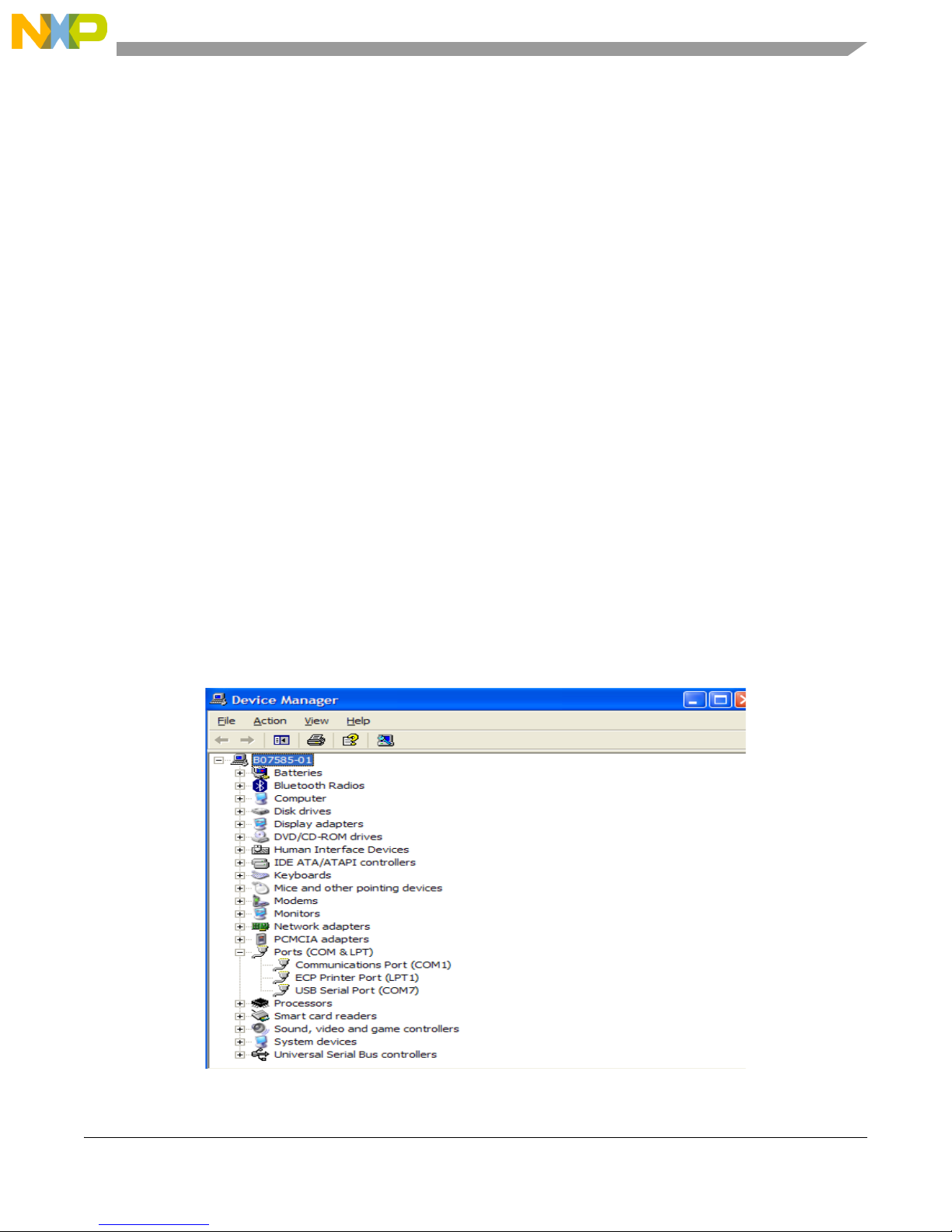
b) Select the Hardware tab, and click the Device Manager button. The Device Manager window
appears as shown in Figure 1-16.
Figure 1-16. COM Port Determination in Device Manager
MC1322x SMAC Demonstration Application User’s Guide, Rev. 1.3
Freescale Semiconductor 1-9
Page 20

Generating an SMAC Application and Port Configuration
c) Scroll to the Ports label and expand the tree by clicking the “+” sign. This shows the COM ports
in the system.
d) As shown in Figure 1-16, the COM Port chosen by the system is titled
USB Serial Port (COM7).
3. If the COM port chosen is not a port numbered between Ports 1-10, then perform the following
tasks:
a) Double click on USB Serial Port in the Device Manager window. The Properties window
appears.
b) Select the Port Settings tab, and then click on the Advanced button.
c) Go to the COM Port Number drop down menu and select a COM port between 1-10 that is not
already in use.
d) Open the Windows System Properties window using Start->Settings->Control Panel->System.
Select the Hardware tab, and click the Device Manager button. The Device Manager window
appears as shown in Figure 1-16.
e) Check to ensure the required port appears.
f) Close the Device Manager window.
4. Proceed to generating the project in BeeKit as described in the appropriate application chapter.
MC1322x SMAC Demonstration Application User’s Guide, Rev. 1.3
1-10 Freescale Semiconductor
Page 21

Chapter 2
Wireless UART Demonstration
The Wireless UART application allows the Freescale ZigBee family of boards to communicate at
typematic rates from one board to another over RS-232 cables or USB virtual COM ports. In order to
execute this demonstration application the user will need a tool to send and receive characters over two
serial ports in addition to what Freescale supply.
This chapter provides a simplified example. Currently, the code cannot be used as a cable replacement. If
cable replacement is the ultimate goal, then queues, buffers, and other constructs must be added to increase
the reliability and efficiency of this demonstration.
Prior to loading the Wireless UART application, the application must be generated using BeeKit, as
described in the BeeKit Wireless Connectivity Toolkit User’s Guide.
The MC1322x SMAC Wireless UART demonstration application is protocol compatible with previous
SMAC Wireless UART applications (those that run on the MC1319x, MC1320x, and MC1321x boards).
However, if security is enabled, the MC1322x SMAC Wireless UART demonstration application is
incompatible with previous SMAC versions.
See Section 1.3, “UART/USB Virtual COM Port Setup” for information about how to set up a virtual COM
port for this application.
2.1 Generating a Project From BeeKit
Once the UART/USB virtual ports have been configured, continue with generating the project from
BeeKit as follows.
1. Open BeeKit (Start->Programs->Freescale BeeKit->Freescale BeeKit).
2. In BeeKit, select the MC1322x SMAC codebase (File menu -> Select Codebase...)
3. Click on File -> New Project and choose the Wireless UART template.
4. Follow the steps as displayed in the New Project wizard.
5. Configure the properties as needed.
6. Validate the solution.
7. Export the solution.
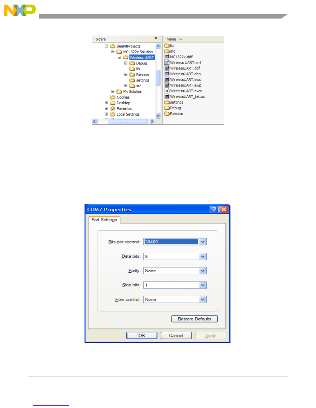
8. BeeKit creates the project folder with the structure as shown in Figure 2-1.
MC1322x SMAC Demonstration Application User’s Guide, Rev. 1.3
Freescale Semiconductor 2-1
Page 22
Wireless UART Demonstration
Figure 2-1. BeeKit Created, Wireless UART Directory Structure
For further details about how to use BeeKit, see the BeeKit Wireless Connectivity Toolkit User’s Guide
(BKWCTKUG).
2.2 Open, Compile and Execute the Wireless UART
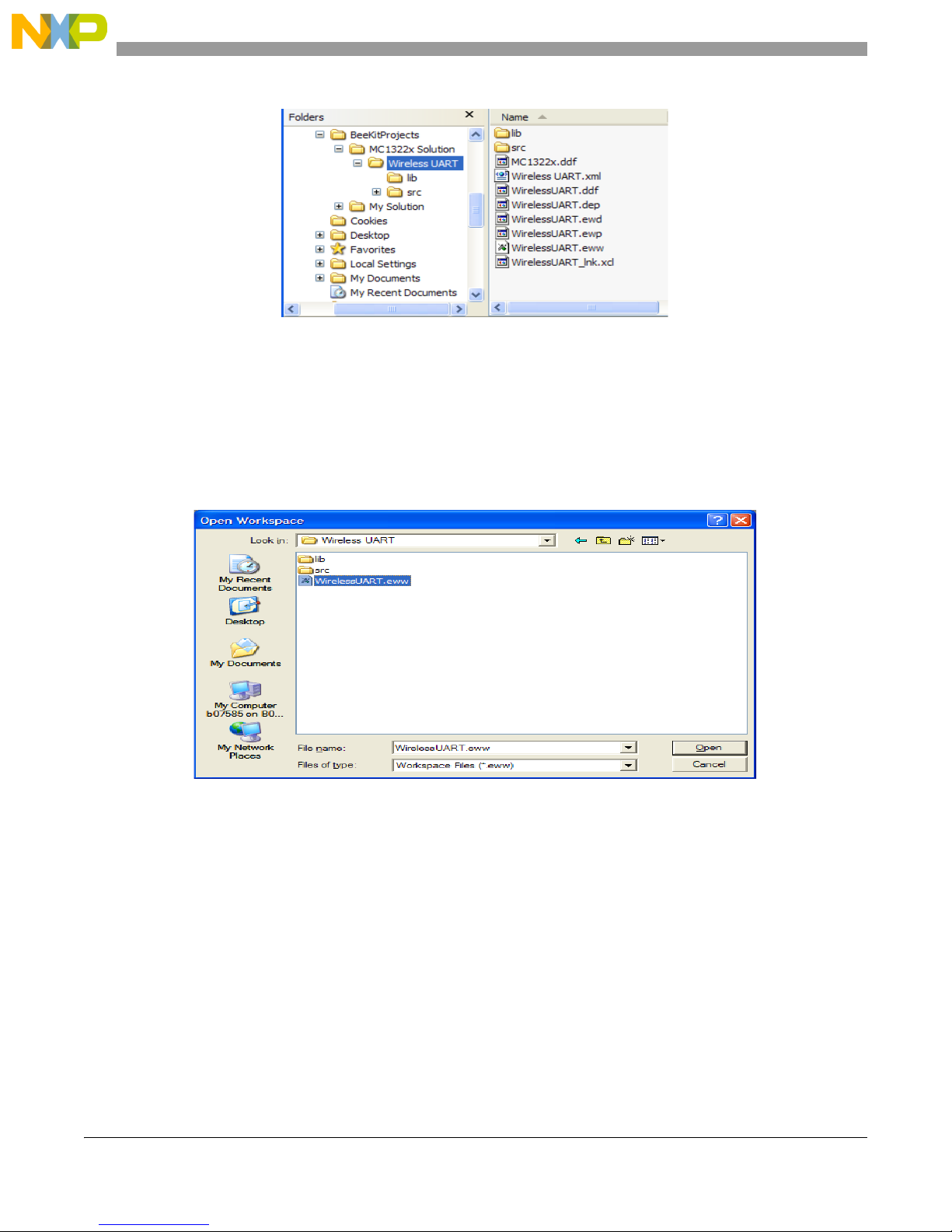
1. Using the IAR Embedded Workbench, open the Wireless UART work space (Wireless UART.eww)
as shown in Figure 2-2.
Figure 2-2. Opening Wireless UART Work Space
2. Select “Release” in the Workspace window.
3. Click on Project -> Rebuild All.
The folders Release, Debug, and the settings are now created in the project structure as shown in
Figure 2-3.
MC1322x SMAC Demonstration Application User’s Guide, Rev. 1.3
2-2 Freescale Semiconductor
Page 23
Wireless UART Demonstration
Figure 2-3. Release, Debug, and Settings
The WirelessUART.bin file is placed at the following directory location:
[Project Directory]\Release\Exe\
4. Load the WirelessUART application to the boards. Connect the JTAG interface to the board, then
click the Debug button on the IAR Embedded Workbench IDE.
5. Use a PC terminal communications program, such as Hyper Terminal, and set the correct baud rate,
data bits, parity, COM port, and flow control. Figure 2-4 shows the default MC1322x SMAC
RS-232 settings.
MC1322x SMAC Demonstration Application User’s Guide, Rev. 1.3
Freescale Semiconductor 2-3
Figure 2-4. Default SMAC RS-232 Settings
Page 24
Wireless UART Demonstration
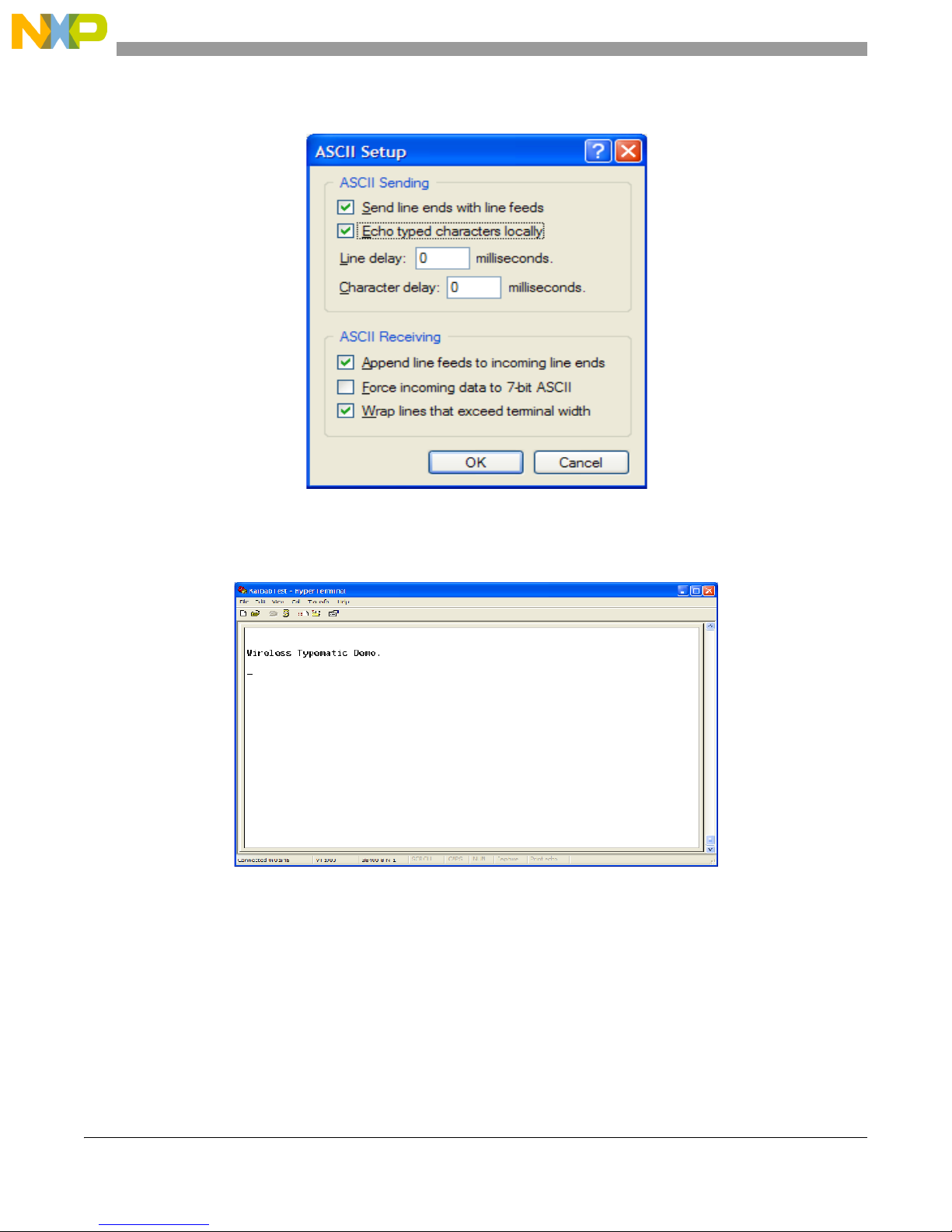
6. In the PC terminal program, set the properties in the optional settings as shown in Figure 2-5.
Figure 2-5. Additional Terminal Program Settings
7. Start the serial communication software and send any characters using the keyboard. The other
board answers with the “Wireless Typematic Demo.“ message as shown in Figure 2-6.
Figure 2-6. Wireless UART Welcome Message
MC1322x SMAC Demonstration Application User’s Guide, Rev. 1.3
2-4 Freescale Semiconductor
Page 25
Wireless UART Demonstration
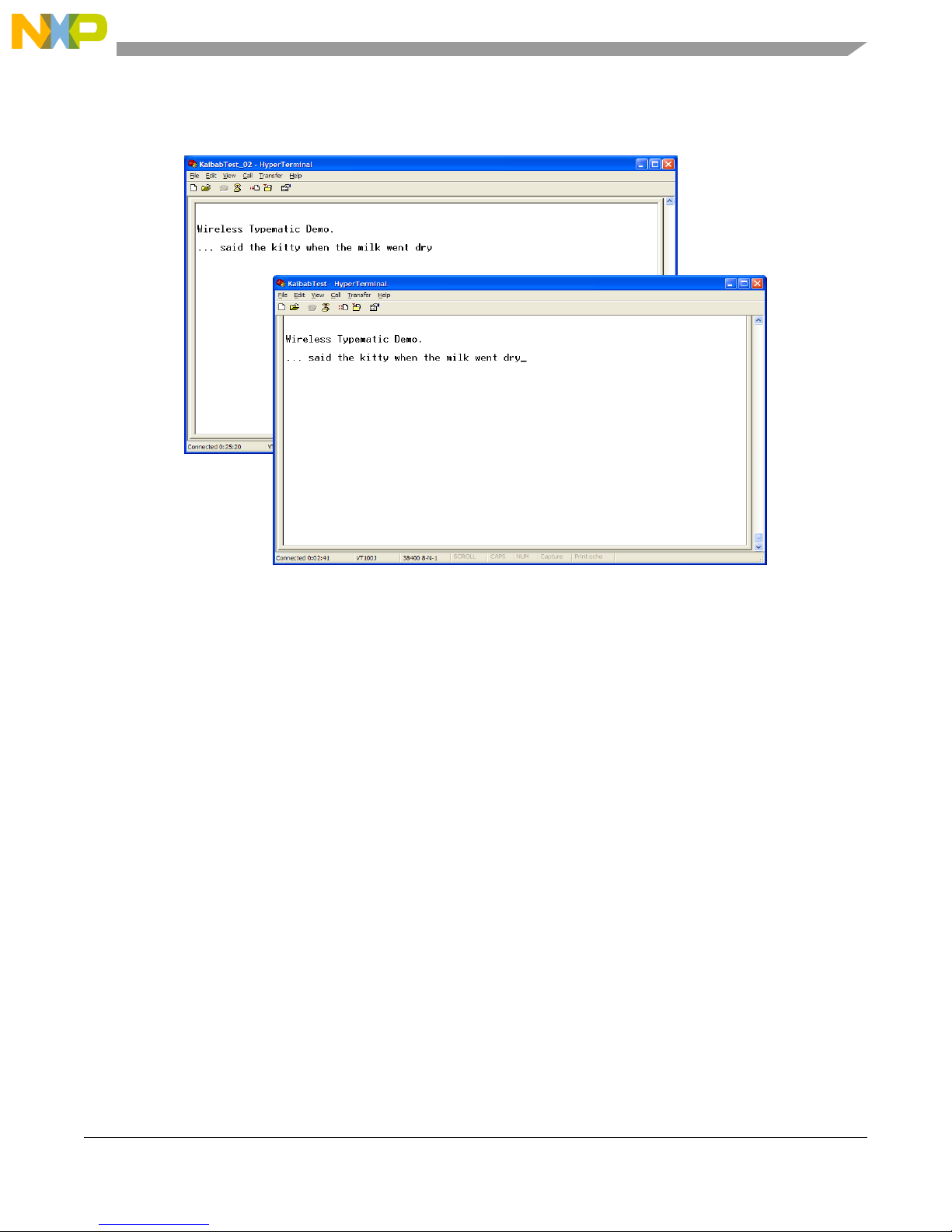
8. Type some characters in the Hyper Terminal Session (Board 1, shown in Figure 2-7) and the typed
message appears on the other PC Hyper Terminal Session (Board 2, also shown in Figure 2-7).
Figure 2-7. Wireless UART Board 1 (Sending) and Board 2 (Receiving)
This is a two-way communication protocol where the boards will retry their packets up to three times if an
acknowledgement is not received. This application highlights a very basic MC1322x SMAC Wireless
UART implementation and as already stated, because it is a basic demonstration application, it is not
intended for large file transfers.
MC1322x SMAC Demonstration Application User’s Guide, Rev. 1.3
Freescale Semiconductor 2-5
Page 26

Wireless UART Demonstration
MC1322x SMAC Demonstration Application User’s Guide, Rev. 1.3
2-6 Freescale Semiconductor
Page 27

Chapter 3
Connectivity Test
The connectivity test evaluates the basic connectivity between two transceivers. A transmitter and a
receiver application are required. The connectivity test supports the following functionality:
• Configure the transceiver in a specific test mode in order to test the transceiver RF performance.
These test mode are:
— Modulated Transmission
— Unmodulated Transmission
— Pulse PRBS Transmission
—IDLE
• Measure the percentage of packet losses over a certain channel as well as the Link Quality Indicator
of each packet received.
• Indicate the range of a signal using the Link Quality Indicator.
In both modes parameters such as the channel number and power level can be modified. This allows users
to execute all tests in every channel using different power values.
The application includes a reference oscillator frequency output at a pin useful for frequency measurement
and adjustment when required.
Two possible interfaces are implemented to use this application: a manual interface through push buttons
or menus for a serial interface. Only one interface can be selected, both interfaces can not been working at
the same time. The interface type is selected when creating the project with the Freescale BeeKit.
For manual interface, the function of each button is as follows:
• SW1: Selects the application mode. (Channel Change, Power Adjust, Test to perform, etc.) see
Figure 3-1.
• SW2: Increases a value.
— For TX the possible options are: IDLE (0), PSRB (1), PER (2), Range Test TX (3), Continuous
Modulated (4) and Continuous Unmodulated (5).
— For RX mode the possible options are: IDLE (0), Continuous reception (1), PER(2) and Range
Test RX (3).
— The values are momentarily shown at the LEDs then LEDs show current application mode.
• SW3: To decrease the value.
• SW4: To start the test (used only at PER test)
MC1322x SMAC Demonstration Application User’s Guide, Rev. 1.3
Freescale Semiconductor 3-1
Page 28

Connectivity Test
Press SW1
Channel
Test
Bulk Capacitor
Fi ne Tune
Press SW1
Initial State
Reset
Power
Press SW1
Press SW1
Press SW1
Coarse Tun e
Press SW1
Channel
Test
Bulk Capacitor
Fi ne Tune
Press SW1
Initial State
Reset
Power
Press SW1
Press SW1
Press SW1
Coarse Tun e
Figure 3-1. Selecting the Application Mode
The functionality of the application could vary according with the selected board. Boards with the serial
port and push buttons support both interfaces, however for boards without serial port or without push
buttons only one interface is possible.
The following sections describe using the serial interface.
3.1 Loading the Connectivity Application
Prior to loading the Connectivity application, the Connectivity Test application must be generated using
BeeKit using the steps shown in Chapter 1, “Generating an SMAC Application and Port Configuration”:
1. Open the [Solution Name].eww file as shown in Figure 3-2.
2. Select Connectivity Test and load this application into two boards as shown in Section 1.1,
“Loading Applications Into a Board Using the JTAG J-Link ARM Debugger”.
Figure 3-2. My Solution EWW File Location
3-2 Freescale Semiconductor
MC1322x SMAC Demonstration Application User’s Guide, Rev. 1.3
Page 29

Connectivity Test
3.2 UART/USB Virtual Com Port Setup
This section describes how to set up the UART/USB virtual Com port for the Connectivity application.
Figure 3-3 shows the default SMAC RS-232 settings.
Figure 3-3. Default SMAC RS-232 Setting
1. Use a PC terminal program and set the correct baud rate, data bits, parity, COM port, and flow
control as shown in .
2. In the PC terminal program, set the properties in the optional settings as shown in Figure 3-4.
Figure 3-4. Additional Terminal Program Settings
MC1322x SMAC Demonstration Application User’s Guide, Rev. 1.3
Freescale Semiconductor 3-3
Page 30

Connectivity Test
3. Connect the Connectivity Test radio to a USB cable. The USB driver is required. Do not use a USB
hub. This driver can be found in the following directory:
<INSTALL DIR>\Freescale\Drivers
The BeeKit CD image is available from the Freescale ZigBee web site at
www.freescale.com/zigbee.
4. See Section 1.3, “UART/USB Virtual COM Port Setup” for information about how to set up a
virtual COM port for this application.
3.3 Starting the Connectivity Test
To start the connectivity test, perform the following tasks:
1. Configure the Com Port as shown in Section 3.2, “UART/USB Virtual Com Port Setup”.
2. Connect each board to a USB cable and a USB port (one PC for each board) and ensure it is enabled
as shown in Section 3.2, “UART/USB Virtual Com Port Setup”.
3. Reset both boards.
The terminal appears as shown in Figure 3-5.
1. Press any key and the following text appears.
_______________________________________
| |
| Connectivity Test Interface |
|______________________________________|
1 - CHANGE CHANNEL
2 - ADJUST OUTPUT POWER
3 - SELECT TEST MODE
4 - ADJUST CLOCK SETTINGS
Note: Case sensitive.
Please select an option:
MC1322x SMAC Demonstration Application User’s Guide, Rev. 1.3
3-4 Freescale Semiconductor
Figure 3-5. Starting the Connectivity Test
Page 31

Connectivity Test
2. Press the appropriate key to perform the associated task.
Users can set the desired channel or power through this menu. RX and TX mode must be operating on the
same channel.
When the “SELECT TEST MODE” (Option 3) is selected, users are routed to a menu to select the
operating mode in which the board is going to work (RX or TX) , this menu option is displayed as shown
in
Figure 3-6.
Figure 3-6. TX / RX Menu
After setting up the mode in which the board is going to work, the menu appears as shown in Figure 3-7.
The Connectivity test options are described in detail in Section 3.4, “Connectivity Test Applications”.
Figure 3-7. Test Mode Menu (Receive on Left, Transmit on Right)
3.4 Connectivity Test Applications
The Connectivity Test application combines the Test Mode application, Packet Error Rate (PER) tests, and
Range Test applications. The following sections describe each of these tests.
MC1322x SMAC Demonstration Application User’s Guide, Rev. 1.3
Freescale Semiconductor 3-5
Page 32

Connectivity Test
3.4.1 Test Mode Application
The Test Mode application allows users to test the RF performance of the transceiver for basic transmitter
and receiver tests. The test mode application is a collection of test modes consisting of the following tests:
• Idle
• Transmission 9th Order Binary Polynomial (PRBS9)
• Reception
• Link Quality Indication
• Transmission with modulation
• Transmission without modulation
3.4.1.1 Selecting the Transmit Mode
Figure 3-8 shows the Transmit Test Mode option that allows users to display the current transmit test mode
and all the possible tests. To select a test mode, press the appropriate key (S, M, U or P).
To test the receiver, the TX board must continuously transmit a packet on the same channel that the RX
application is running. The message received while in receive mode is displayed in the Hyper Terminal
window as shown in Figure 3-9. In this case, the TX board was transmitting the pulse pseudo random
binary sequence.
MC1322x SMAC Demonstration Application User’s Guide, Rev. 1.3
3-6 Freescale Semiconductor
Figure 3-8. Transmission Test Mode Menu
Page 33

Connectivity Test
Figure 3-9. Receive Test Mode
3.4.2 Spectrum Analyzer Captures
The measurements shown in this section are example illustrations of the Test Modes and were captured
from a MC1322x-SRB using the F-antenna. These measurements are radiated measurement and not
conducted measurements.
3.4.2.1 Idle Mode
The Idle Mode captures the noise floor as shown in Figure 3-10.
Figure 3-10. Idle Mode Capture
MC1322x SMAC Demonstration Application User’s Guide, Rev. 1.3
Freescale Semiconductor 3-7
Page 34

Connectivity Test
3.4.2.2 PRBS9Transmit Mode
The PRBS9 Transmit Mode captures the 9th Order Binary Polynomial as shown in Figure 3-11.
Figure 3-11. PRBS9 TX Mode Capture
3.4.2.3 Reception Mode
Figure 3-12 shows the Reception Test Mode. Because the radio is in receive mode, there is little or no
energy captured in the selected channel band.
Figure 3-12. Reception Mode Capture
MC1322x SMAC Demonstration Application User’s Guide, Rev. 1.3
3-8 Freescale Semiconductor
Page 35

3.4.2.4 Transmit with Modulation
Figure 3-13 shows transmitting with modulation.
Connectivity Test
Figure 3-13. TX with modulation Mode Capture
3.4.2.5 Transmit without Modulation (CW Mode)
Figure 3-14 shows Continuous Wave (CW) Mode.
Figure 3-14. TX without modulation Mode Capture
MC1322x SMAC Demonstration Application User’s Guide, Rev. 1.3
Freescale Semiconductor 3-9
Page 36

Connectivity Test
3.5 Packet Error Rate (PER) Test
The Packet Error Rate (PER) test is a unidirectional test that sends a number of packets from a transmitter
to a receiver all on a single channel. The packet length is 18 bytes of data with 2 bytes of SMAC header
for a total of 20 bytes of payload. The results of the packets received by the receiver can be monitored in
two ways:
• Using a PC and a USB connection
• In a standalone mode by reading the count on the LEDs on the board
This test allows for PER testing using a PC.
3.5.1 Starting the PER Test
Ensure that both the Connectivity Test in TX mode board and the Connectivity Test in RX mode board are
on the desired channel. The PER-TX board and the PER-RX board are asynchronous to each other which
means that the PER-TX board does not know when the PER-RX board is on. Users must place the PER-RX
board into Listen Mode prior to setting the PER-TX board into Transmit Packet Mode. If this is done out
of order, the reported packet error rate may be incorrect.
Select Packet Error Rate option on both boards, the Connectivity Test TX and Connectivity Test RX
boards, and follow the instructions at the menus see Figure 3-15 for TX and for RX
Figure 3-15. Selection Packet Error Rate Test
MC1322x SMAC Demonstration Application User’s Guide, Rev. 1.3
3-10 Freescale Semiconductor
Page 37

Figure 3-16. Reception Mode
Connectivity Test
The PER-TX board setup follows a procedure similar to the PER-RX board setup. Place the PER-TX board
on the same channel as the PER-RX going through the Connectivity Test Menus. This ensures that the
PER-TX board is on the same channel as the PER-RX board. Set PER-TX board to place the application
into TX mode. The PER-TX application turns on LEDs 1 through 4 in order to show that the PER-TX
board is in Packet Transmit Mode and then it begins to transmit packets.
3.5.2 PER operation
Since the PER-TX board and the PER-RX board are on the same channel and the PER-RX board started
to listen before the PER-TX board sent any packets, the PER-RX board will toggle LED1 when a packet
is being received. Then the PER-TX board blinks LED1 on every packet that is transmitted. If both boards
are blinking, then both boards are on the same channel. If only the PER-TX board is toggling LED1, then
either the PER-RX board is not in Listen Mode or it is listening to the wrong channel. If this occurs, reset
both boards and try the procedure again without switching channels. If a packet is received, the radio
echoes data to the PC through the UART connection as shown in
• N represents the number of packets received
• L is the length of the packet
• LQI is the Link Quality Indicator (measured in dBm)
• CRC indicates if the Cyclical Redundancy Check (CRC) is good
• Data is the hex formatted payload
Figure 3-17.
MC1322x SMAC Demonstration Application User’s Guide, Rev. 1.3
Freescale Semiconductor 3-11
Page 38

Connectivity Test
Figure 3-17. The UART output during PER test
When the PER-TX board is done sending 1000 packets, the PER-TX board sends packets with the payload
“DONEDONE”. If the PER-RX board receives the “DONEDONE” packet, the application echoes the
total number of good packets received. The measured PER is echoed to the terminal in a 999/1000 format.
When using manual interface the PER value is echoed to the LEDs on the PER-RX board. For example,
if the measured packet received was 983/1000 then at the completion of the test, the value 1001b (9d),
1000b (8d), 0011b (3d) will blink. This example allows PER to be measured without the need for a PC.
3.6 Range Test
The range test uses the LQI in order to monitor the variation of distance between the transmitter and the
receiver in a normal transmission. This test uses two devices one configured as transmitter and the other
as receiver.
In the range test, the transmitter sends a message and waits for an acknowledge packet, then the receptor
calculates the LQI of the received packet and sent it to the transmitter into the acknowledge packet. In both
devices (transmitter and receiver) the LQI value is indicated through LEDs in the manual interface, when
serial interface is used the LQI value is sent to the serial terminal. This process is repeated until the user
finishes the test. See Figure 3-18
MC1322x SMAC Demonstration Application User’s Guide, Rev. 1.3
3-12 Freescale Semiconductor
Page 39

Figure 3-18. Range Test Stop and Start
Connectivity Test
3.7 Crystal Adjustment
The Connectivity Test application includes a utility to help adjust the onboard trim capacitance for the
MC1322x 24 MHz crystal reference oscillator. The trim capacitance can be changed to center the oscillator
frequency on the target 24 MHz, thus minimizing the error frequency (in ppm).
NOTE
For more information on tuning the oscillator, see the MC1322x Reference
Manual.
The reference frequency cannot be monitored directly via a GPIO pin, so as a substitute, the application
provides 2 MHz frequency derived from the reference oscillator and makes it available on the TMR1
signal pin.
To use this utility the “ADJUST CLOCK SETTINGS” option must be selected from the terminal main
menu.
When the “ADJUST CLOCK SETTINGS“ option is selected, the terminal displays the following menu.
_____________________
| |
| Clock Settings Menu |
|_____________________|
1 - Set Bulk 4 pF CAP.
2 - Adjust COARSE TUNE
3 - Adjust FINE TUNE
p - Previous Menu
MC1322x SMAC Demonstration Application User’s Guide, Rev. 1.3
Freescale Semiconductor 3-13
Page 40

Connectivity Test
Please select an option:
There are only two options for the “Set Bulk 4 pF CAP” (bulk capacitor) option:
• Enable the 4 pF capacitor
• Disable the 4 pF capacitor
For the “Adjust COARSE TUNE” and the “Adjust FINE TUNE” options:
• Either the coarse tune or the fine tune is adjusted respectively.
• The user must enter a value for either parameter.
— The possible values are 0x00 to 0x0F for the coarse tune parameter
— The possible values are0x00 to 0x1F for the fine tune parameter.
— The application verifies that the value entered is between these ranges; if not the value is
rejected and the parameter value is not updated.
The crystal frequency adjustment is performed using the provided 2 MHz TMR1 reference signal. Use a
frequency counter to measure ppm. The trim should be adjusted typically to less than +/-5 to +/-10 ppm.
NOTE
The TMR1 pin on the Freescale Network Node Evaluation Board is also
used by the LCD control. The LCD cannot be used while the crystal
adjustment test is being utilized.
MC1322x SMAC Demonstration Application User’s Guide, Rev. 1.3
3-14 Freescale Semiconductor
Page 41

Chapter 4
Accelerometer Demonstration
The Accelerometer Demonstration application shows various uses of the Freescale X, Y, and Z axes
accelerometers.
NOTE
When using the 13226-SRB, the Accelerometer Demonstration application
is not supported because the 13226-SRB does not have an accelerometer. If
users select and export this application in BeeKit, the results will not be
accurate.
4.1 Loading the Accelerometer Application
1. Flash the Accelerometer Demonstration into two boards. One board must be either a MC1322X
Sensor Node (also compatible with 13192-SARD or MC13213-SRB) to provide the X, Y, and Z
axes accelerometer data and the other board must have an available UART and be able to connect
to a PC. This example uses two MC1322x Sensor Node boards.
2. If users need to run the Accelerometer on different targets, those projects must be generated by
BeeKit as described in Chapter 1, “Generating an SMAC Application and Port Configuration”.
3. Download the appropriate target image by following the procedure in Section 1.1, “Loading
Applications Into a Board Using the JTAG J-Link ARM Debugger”.
4.2 Board Setup
To setup both boards for operation (transmit and receive), perform the steps shown in this section.
4.3 Board One Setup (PC_Radio Board)
1. Connect a Sensor Node Board to the PC using the USB cable included in the kit. (Do not use a hub.)
2. Power on the board by setting the Power Switch to the ON position.
3. Press the Reset Button once. The LEDs are off, but the PC_Radio application is running and in
receive mode.
4.4 Board Two Setup (Accelerometer Board)
1. Connect 9 VDC power to DC power connector with the 9 VDC wall transformer included in the
kit. Power on the board by setting the Power Switch (S100) to the ON position. Another board
power option is to use the batteries which provides the advantage of true wireless operation (no
cables) and allows users to easily move and manipulate the SRB.
2. Press the Reset Button once.
MC1322x SMAC Demonstration Application User’s Guide, Rev. 1.3
Freescale Semiconductor 4-1
Page 42

Accelerometer Demonstration
3. Press button SW1 once and LED3 will momentarily flash to indicate Application Two is running
(Accelerometer Mode).
4. The Accelerometer application sends a ping packet to the PC_Radio every two seconds. This is
indicated on the Accelerometer Board by a blinking LED2.
5. The Accelerometer application detects when the Accelerometer Board is moved and quickly
toggles LED1, then sends a packet to the PC_Radio Board with an updated reading.
4.5 PC Setup
1. If the Evaluation Kit tools are already installed, then users can run the Triax software by navigating
to the link using the Start menu.
2. From Windows, select Start->Programs->Freescale BeeKit->Triax.
a) If the Triax application does not exist, go to Step 3 to install it.
b) If the application is in the Start Menu, go to Step 4.
3. To run only the Triax application, insert the CD supplied with the kit into the PC CD-ROM drive.
4. Run the Triax.exe file from the selected install location on the PC hard drive.
5. The Triax application is set up to run on COM ports 1-10. To check which COM port is being used
by the USB, perform the following tasks:
a) Open the System Properties window by clicking on Start->Settings->Control Panel->System.
b) Select the Hardware tab, and click the Device Manager button. The Device Manager window
appears as shown in Figure 4-1.
c) Scroll to the “Ports” label and expand the tree by clicking the “+” sign to show the COM ports
in the system.
d) The COM Port selected by the system is titled USB Serial Port(COM24) as shown in Figure 4-1.
MC1322x SMAC Demonstration Application User’s Guide, Rev. 1.3
4-2 Freescale Semiconductor
Page 43

Figure 4-1. COM Port Determination in Device Manager
Accelerometer Demonstration
6. If the COM port chosen for Freescale Zigbee/802.15.4 MAC COM Device is not a port within Ports
1-10, then perform the following tasks:
a) Double click on Freescale Zigbee/802.15.4 MAC COM Device in the Device Manager window
and the Properties window will appear.
b) Select the Port Settings tab and then click the Advanced button.
c) Go to the Com Port Number drop down menu and select a COM port between 1-10 that is not
in use.
4.6 Verifying Operation
1. Check for the ping packet. The Accelerometer application sends a ping packet to the PC_Radio
every two (2) seconds as indicated by LED2. The Accelerometer Board quickly blinks LED2
indicating that the ping packet is sent. The PC_Radio receives the ping and toggles LED2 upon
reception. Once connectivity between the PC_Radio and the Accelerometer Board is verified, go
to Step 2.
2. To check if the Accelerometer Board is working, move the Accelerometer Board. LED1 blinks,
which indicates that the Accelerometer Board has detected movement.
3. With the default application, data that represents movement of the Accelerometer Board is sent to
the PC_Radio. When the PC_Radio receives this data, LED2 toggles.
4. Select the Raw Data applet from the Triax application. The Raw Data applet shows the X, Y, and
Z axes A/D values as reported by the Accelerometer Board. When the board is laying flat, the raw
values should read approximately 0g for both the X and Y axes. However, the Z axis should read
approximately 1g. As shown in Figure 4-2, when the Accelerometer Board is moved, the values of
the X, Y, and Z axes are updated on the Raw Data applet.
MC1322x SMAC Demonstration Application User’s Guide, Rev. 1.3
Freescale Semiconductor 4-3
Page 44

Accelerometer Demonstration
Figure 4-2. Raw Data Demonstration
NOTE
To improve accuracy of the accelerometer readings, refer to Section 4.7,
“Setting Up the Calibration Application”.
The Triax main window appears as shown in Figure 4-3.
MC1322x SMAC Demonstration Application User’s Guide, Rev. 1.3
4-4 Freescale Semiconductor
Figure 4-3. Triax Main Window
Page 45

Accelerometer Demonstration
When the accelerometer is moved, the Accelerometer Board sends data to the PC_Radio to update its data.
Data is only sent when it changes within a small tolerance.
The receiver receives these packets and updates its cached value of the accelerometer data. The PC
periodically sends a command string through the USB to the PC_Radio that requests the accelerometer
data. This data is interpreted by the Triax software to enable several applications and demonstrations.
MC1322x SMAC Demonstration Application User’s Guide, Rev. 1.3
Freescale Semiconductor 4-5
Page 46

Accelerometer Demonstration
4.7 Setting Up the Calibration Application
In order to verify and visualize the calibration procedure, the Triax.exe PC GUI must be running, but it is
not required.
1. Press the Reset button on the PC_Radio Board once. (Out of reset, the PC application is running.)
2. Press the Reset button on the Accelerometer Board once.
3. Place the Accelerometer Board on a flat surface. (component side up)
4. Press SW1 on the Accelerometer Board to advance the application to the Accelerometer Mode
(Application Two). LED3 momentarily lights to indicate that Application Two is running. The
Accelerometer Board sends out a ping packet every two (2) seconds and updates the data on the
XYZ Demo PC application each time the board is moved.
5. If the data points for the X, Y, and Z axes shown on the PC GUI are not near the origin of the graph,
then continue to Step 6.
6. Press SW4 on the Accelerometer Board once until all LEDs are lit. This shows that the calibration
is being performed.
7. Verify that the Accelerometer Board is calibrated by viewing the X, Y, and Z axes on the PC GUI.
The squares on the display should be approximately at axis point 0,0. If the calibration is still
incorrect, repeat the calibration process until the data points are nominally at axis point 0,0.
8. To quit, exit the application in the GUI and press reset on both boards. Press SW1 on the
Accelerometer Board once to return to main application functionality.
MC1322x SMAC Demonstration Application User’s Guide, Rev. 1.3
4-6 Freescale Semiconductor
Page 47

Chapter 5
Low Power Bell Demonstration
The Low Power Bell Demonstration consists of a transmitter (TX) and receiver (RX). The Low Power Bell
TX application serves as the bell switch and demonstrates low power modes and how to implement them.
The Low Power Bell RX application serves as the bell and makes a sound when it receives a new packet
from the Low Power Bell TX application.
Freescale recommends using the 1322x-LPN Low Power Node to best demonstrate low power
capabilities.
5.1 Generating the Project From BeeKit
To generate the project from BeeKit.
1. Open BeeKit (Start->Programs->Freescale BeeKit->Freescale BeeKit).
2. In BeeKit, select the MC1322x SMAC codebase (File menu -> Select Codebase...)
3. Click on File -> New Project and choose the Low Power Bell TX template.
4. Follow the steps as displayed in the New Project wizard.
5. Add the Low Power Bell RX project to the current solution.
6. Configure the properties as needed.
7. Be sure to configure the Low Power Bell TX and Low Power Bell RX applications both on the
same channel.
8. Validate the solution.
9. Export the solution.
For further details about how to use BeeKit, see the BeeKit Wireless Connectivity Toolkit User’s Guide
(BKWCTKUG).
5.2 Open, Compile and Execute the Low Power Bell Application
1. Using the IAR Embedded Workbench, open the Generic Application work space (My
Solution.eww) as shown in Figure 5-1.
MC1322x SMAC Demonstration Application User’s Guide, Rev. 1.3
Freescale Semiconductor 5-1
Page 48

Low Power Bell Demonstration
Figure 5-1. Opening Generic Application Space
2. Chose the “Low Power Bell TX” tab.
3. Select “Release” in the Workspace window.
4. Click on Project -> Rebuild All.
The folders Release, Debug, and the settings are now created in the project structure as shown in
Figure 5-2.
MC1322x SMAC Demonstration Application User’s Guide, Rev. 1.3
5-2 Freescale Semiconductor
Figure 5-2. Release, Debug, and Settings
Page 49

Low Power Bell Demonstration
The Low Power Bell Tx.bin file is located at the following directory location:
[Project Directory]\Release\Exe\
5. Use the JTAG interface to load the Low Power Bell TX application on the board being used as the
Low Power Bell TX. Connect the JTAG interface to the board, then click the Debug button at the
IAR Embedded Workbench IDE.
6. Choose the “Low Power Bell RX” tab.
7. Repeat Steps 3 and 4.
The Low Power Bell RX.bin file is located at the following directory location:
[Project Directory]\Release\Exe\
8. Use the JTAG interface to load the Low Power Bell RX application on the board being used as the
Low Power Bell RX. Click the IAR Debug button to download the application to the board.
9. Reset both boards.
Pressing SW1 on the Low Power TX board sounds the buzzer on the Low Power Bell RX board.
MC1322x SMAC Demonstration Application User’s Guide, Rev. 1.3
Freescale Semiconductor 5-3
Page 50

Low Power Bell Demonstration
MC1322x SMAC Demonstration Application User’s Guide, Rev. 1.3
5-4 Freescale Semiconductor
Page 51

Chapter 6
Generic Application Demonstration
The SMAC codebase includes a Generic Application Demonstration that can be used as template to
develop proprietary applications. This application shows all the initialization required to start the radio
and the commonly used peripherals such as UART and KBIs.
See Section 1.3, “UART/USB Virtual COM Port Setup” for information about how to set up a virtual COM
port for this application.
6.1 Generating a Project From BeeKit
Once the UART/USB virtual ports have been configured, generate the project from BeeKit.
1. Open BeeKit (Start->Programs->Freescale BeeKit->Freescale BeeKit).
2. In BeeKit, select the MC1322x SMAC codebase (File menu -> Select Codebase...)
3. Click on File -> New Project and choose the Generic Application template.
4. Follow the steps as displayed in the New Project wizard.
5. Configure the properties as needed. Choose the manual interface for the KBI.
6. Validate the solution
7. Export the solution.
For further details about how to use BeeKit, see the BeeKit Wireless Connectivity Toolkit User’s Guide
(BKWCTKUG).
6.2 Open, Compile and Execute the Generic Application
1. Using the IAR Embedded Workbench, open the Generic Application work space (My
Solution.eww
) as shown in Figure 6-1.
Figure 6-1. Opening Generic Application Space
MC1322x SMAC Demonstration Application User’s Guide, Rev. 1.3
Freescale Semiconductor 6-1
Page 52

Generic Application Demonstration
2. Select “Release” in the Workspace window.
3. Click on Project -> Rebuild All.
The folders Release, Debug, and the settings are now created in the project structure as shown in
Figure 6-2.
Figure 6-2. Release, Debug, and Settings
The WirelessUART.bin file is placed at the following directory location:
[Project Directory]\Release\Exe\
4. Load the Generic Application file to a board using the JTAG interface. Connect the JTAG
interface to the board, then click the Debug button at the IAR Embedded Workbench IDE.
5. Use a PC terminal communications program, such as Hyper Terminal, and set the correct baud rate,
data bits, parity, COM port, and flow control. Figure 6-3 shows the default MC1322x SMAC
RS232 settings.
MC1322x SMAC Demonstration Application User’s Guide, Rev. 1.3
6-2 Freescale Semiconductor
Figure 6-3. Default SMAC RS-232 Settings
Page 53

Generic Application Demonstration
6. In the PC terminal program, set the properties in the optional settings as shown in Figure 6-4.
Figure 6-4. Additional Terminal Program Settings
7. Start the serial communication software ant reset the board. Text is displayed in the Hyper Terminal
window as shown in the Figure 6-5,
At this point users have an empty project to start their own application.
MC1322x SMAC Demonstration Application User’s Guide, Rev. 1.3
Freescale Semiconductor 6-3
Figure 6-5. Generic Application Message
Page 54

Generic Application Demonstration
MC1322x SMAC Demonstration Application User’s Guide, Rev. 1.3
6-4 Freescale Semiconductor
Page 55

Chapter 7
Simple ZigBee Test Client (SZTC) Demonstration
The Simple ZigBee Test Client (SZTC) application allows users to test the SMAC primitives by sending
special data frames through the Serial/USB port. The SZTC application requires two boards and the
appropriate Python scripts to communicate with the boards or a serial port packet generator.
Prior to loading the SZTC application, the application must be generated using BeeKit as described in the
BeeKit Wireless Connectivity Toolkit User’s Guide.
See Section 1.3, “UART/USB Virtual COM Port Setup” for information about how to set up a virtual COM
port for this application.
7.1 Generating a Project From BeeKit
Once the UART/USB virtual ports have been configured proceed to generate the project from BeeKit.
1. Open BeeKit (Start->Programs->Freescale BeeKit->Freescale BeeKit).
2. In BeeKit, select the MC1322x SMAC codebase (File menu -> Select Codebase...)
3. Click on File -> New Project and choose the Simple ZTC template.
4. Follow the steps as displayed in the New Project wizard.
5. Configure the properties as needed.
6. Validate the solution
7. Export the solution.
For further details about how to use BeeKit, see the BeeKit Wireless Connectivity Toolkit User’s Guide
(BKWCTKUG).
7.2 Testing the SZTC with the WirelessUART
1. Download the SZTC application to the board that will be used as the tester.
2. Download the WirelessUART application to a board that will be used as the subject of the test.
3. Open a HyperTerminal session (or another compatible communications program) and configure it
for serial communications using the following parameters:
—8 Bits
—No Parity
— 1 Stop
— 38400 Baud
— No Flow control
MC1322x SMAC Demonstration Application User’s Guide, Rev. 1.3
Freescale Semiconductor 7-1
Page 56

Simple ZigBee Test Client (SZTC) Demonstration
4. Connect the board that is running the WirelessUART application to the serial port of the PC and
press that board’s reset button. A message appears on the PC display as shown in Figure 7-1.
Figure 7-1. Wireless UART Application
5. Open the Freescale Test Tool located in the following directory:
Programs/Freescale BeeKit/Test Tool
6. As shown in Figure 7-2, from the Test Tool window, select Tools -> Communication Settings.
Figure 7-2. Test Tool Communication Settings
MC1322x SMAC Demonstration Application User’s Guide, Rev. 1.3
7-2 Freescale Semiconductor
Page 57

Simple ZigBee Test Client (SZTC) Demonstration
7. Create a new serial connection for the board running the SZTC application by clicking the “Add
Internal“ button in the “List Of Devices” window as shown in Figure 7-3.
Figure 7-3. List of Devices Window
8. Select the appropriate COM port and set the baud rate at 19200 as shown in Figure 7-4.
9. Click the OK button.
MC1322x SMAC Demonstration Application User’s Guide, Rev. 1.3
Freescale Semiconductor 7-3
Figure 7-4. Device Settings
Page 58

Simple ZigBee Test Client (SZTC) Demonstration
10. The List of Devices window appears again as shown in Figure 7-5. Disable all connections except
the SZTC connection that was just created by highlighting the connection to be disabled and
clicking on the Disable button. The disabled connections are should now be grayed out.
Figure 7-5. Disable Unused Devices
11. As shown in Figure 7-6, use the Test Tool main menu to open the Script Server application by
clicking on View -> Script Server. See the Freescale Test Tool User’s Guide for more details about
Test Tool.
Figure 7-6. Test Tool Launch Script Server
MC1322x SMAC Demonstration Application User’s Guide, Rev. 1.3
7-4 Freescale Semiconductor
Page 59

Simple ZigBee Test Client (SZTC) Demonstration
The Script Server window appears as shown in Figure 7-7. See the Freescale Test Tool User’s
Guide for more details about Script Server.
Figure 7-7. Test Tool Adding a Python (py) script
12. Load the Sending Letters To The Wireless Uart.py Python script, which is located in the
following directory:
~\Program Files\Freescale\BeeKit\Test Tool\Scripts\SMAC\Demo Scripts\
13. Click on the Execute button to run the script.
14. On the PC running the Serial Terminal application and is connected to the board running the
WirelessUART application, the expected end results are shown in Figure 7-8. If this is not the end
result, try running the WirelessUART application on the SZTC again.
Figure 7-8. Result at the Wireless UART Application
MC1322x SMAC Demonstration Application User’s Guide, Rev. 1.3
Freescale Semiconductor 7-5
Page 60

Simple ZigBee Test Client (SZTC) Demonstration
MC1322x SMAC Demonstration Application User’s Guide, Rev. 1.3
7-6 Freescale Semiconductor
Page 61

Chapter 8
Repeater Demonstration
The Repeater application increases the range between two boards or monitors the activity on an SMAC
based communication system. To execute this demonstration application, user need a tool to send and
receive characters over two serial ports in addition to what Freescale supplies.
This chapter provides a simplified example. Currently, the code cannot be used as a generic repeater, this
application implements two modes of repeater and an SMAC sniffer.
Prior to loading the Repeater demonstration application, the application must be generated using BeeKit,
as described in the BeeKit Wireless Connectivity Toolkit User’s Guide.
The MC1322x SMAC Repeater demonstration application is consistent with previous SMAC Repeater
applications (those that run on the MC1319x, MC1320x, and MC1321x boards) but implements a new
SMAC sniffer which is a demonstration on how to monitor SMAC communication.
See Section 1.3, “UART/USB Virtual COM Port Setup” for information about how to set up a virtual COM
port for this application.
8.1 Generating a Project From BeeKit
Once the UART/USB virtual ports have been configured proceed to generate the project from BeeKit.
1. Open BeeKit (Start->Programs->Freescale BeeKit->Freescale BeeKit).
2. In BeeKit, select the MC1322x SMAC codebase (File menu -> Select Codebase...)
3. Click on File -> New Project and choose the Repeater template.
4. Follow the steps as displayed in the New Project wizard.
5. Configure the properties as needed.
6. Validate the solution
7. Export the solution.
Create the project folder with the structure as shown in Figure 8-1.
MC1322x SMAC Demonstration Application User’s Guide, Rev. 1.3
Freescale Semiconductor 8-1
Page 62

Repeater Demonstration
Figure 8-1. BeeKit Created, Wireless UART Directory Structure
For further details about how to use BeeKit, see the BeeKit Wireless Connectivity Toolkit User’s Guide
(BKWCTKUG).
8.2 Open, Compile and Execute the Repeater
1. Using the IAR Embedded Workbench, open the Repeater work space (My Solution.eww) as shown
in Figure 8-2.
Figure 8-2. Opening Repeater Work Space
2. Select “Release” in the Workspace window.
3. Click on Project -> Rebuild All.
MC1322x SMAC Demonstration Application User’s Guide, Rev. 1.3
8-2 Freescale Semiconductor
Page 63

Repeater Demonstration
The folders Release, Debug, and the settings are now created in the project structure as shown in
Figure 8-3.
Figure 8-3. Release, Debug, and Settings
The Repeater.bin file is placed at the following directory location:
[Project Directory]\Release\Exe\
4. Load the Repeater file to the board. Click the IAR Debug button to download the application to the
board.
5. Use a PC terminal communications program, such as Hyper Terminal, and set the correct baud rate,
data bits, parity, COM port, and flow control. Figure 8-4 shows the default MC1322x SMAC
RS232 settings.
MC1322x SMAC Demonstration Application User’s Guide, Rev. 1.3
Freescale Semiconductor 8-3
Figure 8-4. Default SMAC RS-232 Settings
Page 64

Repeater Demonstration
6. In the PC terminal program, set the properties in the optional settings as shown in Figure 8-5.
Figure 8-5. Additional Terminal Program Settings
7. Start the serial communication software and reset the board. The start window appears as shown in
Figure 8-6.
Figure 8-6. Repeater Start Window
MC1322x SMAC Demonstration Application User’s Guide, Rev. 1.3
8-4 Freescale Semiconductor
Page 65

Repeater Demonstration
8. Type any key at the serial terminal software and the repeater menu appears as shown in Figure 8-7.
Figure 8-7. Repeater menu and configuration
8.3 Repeater Menu, Configuration and Settings
The Repeater menu displays eight options:
<s> Show Statistics
<0> Reset Statistics
<r> Repeat menu
<m> Switch Repeater mode
<p> Change Power
<d> Change Delay length
<c> Switch Channel
<z> EXECUTE
To select an option, type the character corresponding the desired option on the serial terminal. The options
are case sensitive.
1. Type “s” to show repeater statistics as shown in Figure 8-8.
Figure 8-8. Repeater Statistics
Received The number of frames that have been received.
Retransmitted The number of frames retransmitted.
Bad The number of packets received corrupted.
MC1322x SMAC Demonstration Application User’s Guide, Rev. 1.3
Freescale Semiconductor 8-5
Page 66

Repeater Demonstration
Dropped The number of frames that has been received but not retransmitted. This is used
on the NORMAL mode. Detail about Normal, Dummy, and Sniff modes are
covered later in this section.
2. Type “0” (zero) to reset statistics.
3. Type “r” to show repeater’s menu.
4. Type “m” to switch between repeater’s operational modes: NORMAL, DUMMY and SNIFF.
Normal The application receives a message and wait “Delay Length“ to receive other
messages before retransmitting. If a second message is received, the original
received packet is dropped and not retransmitted.
Dummy Anything that is received is retransmitted as soon as possible.
Sniff The application shows the messages received and does not retransmit anything.
5. Type “p“ to change radio’s output power. The power increases each time “p” is typed until the
maximum value is reached. When the maximum value is reached, it resets to the minimum value
and begins increasing again. See Figure 8-9.
Figure 8-9. Power output adjustment
6. Type “d“ to change the “Delay Length“ value. See Figure 8-10.
Figure 8-10. Change Delay Length
MC1322x SMAC Demonstration Application User’s Guide, Rev. 1.3
8-6 Freescale Semiconductor
Page 67

Repeater Demonstration
7. Type “c“ to switch channel.
8. Press “z” to execute the repeater, to quit press any key.
8.4 Running the Repeater Demonstration
1. Configure the repeater settings as needed, as shown in Section 8.3, “Repeater Menu, Configuration
and Settings”.
2. To start running the application press “z” at the main menu.
3. To stop the application press any key.
8.4.1 Creating a Sniffer
To create a sniffer on Channel 13 set to check for max power, perform the following tasks:
1. Start a serial terminal as shown in Section 8.2, “Open, Compile and Execute the Repeater”.
2. Reset a board with the repeater application flashed.
3. Press “c“ key as many times as needed until Channel is set to 13.
4. Press “p” key as many times as needed until Power Level is set to 18.
5. Press “m” key as many times as needed until App Mode is set to SNIFF.
6. Press “z” key to start sniffing Channel 13.
7. Configure any SMAC demonstration application to transmit on Channel 13 and start that
application.
8. The over the air packets on Channel 13 will be displayed on the terminal attached to the repeater
application.
9. To stop the sniffer, press any key at the terminal interface used by the sniffer application.
8.4.2 Running a Dummy Repeater
To run a dummy repeater on channel 11, perform the following tasks.
1. Start a serial terminal as shown in Section 8.2, “Open, Compile and Execute the Repeater”.
2. Reset a board that has the repeater application FLASHED on it.
3. Press “c“ key as many times as needed until Channel is set to 11.
4. Press “m” key as many times as needed until App Mode is set to DUMMY.
5. Press “z” key to start the repeater.
6. Use another board configured with the Wireless UART Demo set to Channel 11.
7. Start the Wireless UART application.
8. Each character transmitted shows its echo because the message is being retransmitted by the
repeater.
9. To stop the repeater, press any key at the terminal interface used by the repeater application.
MC1322x SMAC Demonstration Application User’s Guide, Rev. 1.3
Freescale Semiconductor 8-7
Page 68

Repeater Demonstration
MC1322x SMAC Demonstration Application User’s Guide, Rev. 1.3
8-8 Freescale Semiconductor
Page 69

Chapter 9
Weather Station Demonstration
The Weather Station demonstration application ships as part of the MC1322x Developer Starter Kit and is
also included as a demonstration in the BeeKit ARM7 SMAC Codebase. The Weather Station
demonstration application simulates some weather station data and shows the use of Freescale sensors for
acceleration and pressure. This Weather Station demonstration consists of three components:
• Weather Station Controller using the Network Node
• Weather Station Sensor using the Sensor Node
• Weather Station PC GUI application
This chapter provides a simplified example. Currently, the code does display actual weather station data,
but provides simulated data for demonstration purposes only.
Prior to loading the Weather Station demonstration application, the applications must be generated using
BeeKit, as described in the BeeKit Wireless Connectivity Toolkit User’s Guide.
The Weather Station demonstration application was developed for the MC1322x. There are no previous
versions for the MC13213-SRB, MC13213-NCB or other Freescale ZigBee legacy boards.
See Section 1.3, “UART/USB Virtual COM Port Setup” for information about how to set up a virtual COM
port for this application.
NOTE
When using the 13226-SRB, the Weather Station Demonstration application
is not supported because the 13226-SRB does not have an accelerometer. If
users select and export this application in BeeKit, the results will not be
accurate.
9.1 Generating a Project From BeeKit
Once the UART/USB virtual ports have been configured proceed to generating the project from BeeKit.
1. Open BeeKit (Start->Programs->Freescale BeeKit->Freescale BeeKit).
2. In BeeKit, select the MC1322x SMAC codebase (File menu -> Select Codebase...)
3. Click on File -> New Project and choose the Weather Station Controller template.
4. Follow the steps as displayed in the New Project wizard.
5. Click on File -> New Project and choose the Weather Station Sensor Node template.
6. Follow the steps as displayed in the New Project wizard.
7. Configure the properties as needed.
8. Validate the solution
MC1322x SMAC Demonstration Application User’s Guide, Rev. 1.3
Freescale Semiconductor 9-1
Page 70

Weather Station Demonstration
9. Export the solution.
MC1322x SMAC Demonstration Application User’s Guide, Rev. 1.3
9-2 Freescale Semiconductor
Page 71

Weather Station Demonstration
BeeKit creates the project folder with the structure as shown in Figure 9-1.
Figure 9-1. BeeKit Created, Wireless UART Directory Structure
For further details about how to use BeeKit, see the BeeKit Wireless Connectivity Toolkit User’s Guide
(BKWCTKUG).
9.2 Open, Compile, and Load the Weather Station
1. Using the IAR Embedded Workbench, open the [My Solution] work space (MySolution.eww) as
shown in Figure 9-2.
Figure 9-2. Opening Weather Station Work Space
2. Select “Release” in the Workspace window.
3. With the “Weather Station Controller“ highlighted, click on Project -> Rebuild All.
The folders Release, Debug, and the settings are now created in the project structure as shown in
Figure 9-3.
MC1322x SMAC Demonstration Application User’s Guide, Rev. 1.3
Freescale Semiconductor 9-3
Page 72

Weather Station Demonstration
4. With the “Weather Station Sensor Node“ highlighted, click on Project -> Rebuild All.
The folders Release, Debug, and the settings are now created in the project structure similar to what is
shown in Figure 9-3.
Figure 9-3. Release, Debug, and Settings
The Weather Station Controller.bin file is placed at the following directory location:
[My Solution Directory]\Weather Station Controller\Release\Exe\
The Weather Station Sensor Node.bin file is placed at the following directory location:
[My Solution Directory]\Weather Station Sensor Node\Release\Exe\
5. Load the Weather Station Controller.bin and Weather Station Sensor Node.bin files to the
boards using the JTAG connection. To download the image, connect the J-Link ARM debugger and
press [Ctrl]+D or just click the Debug button at the IAR Embedded Workbench IDE.
6. At this point the weather station is running without the PC Application. After showing the
Freescale logo, the “Wind Speed“ screen appears on the Network Node LCD display as shown in
Figure 9-4.
MC1322x SMAC Demonstration Application User’s Guide, Rev. 1.3
9-4 Freescale Semiconductor
Page 73

Weather Station Demonstration
Figure 9-4. Network Node Board LCD Display
7. Use the Network Node joystick or switches to change the parameters as follows:
Figure 9-5. Joystick or Switch Parameters
Joystick
Position
Joystick Right SW1 Metric/Standard System Selection Set calibration
Joystick Down SW2 Switch Screen. Change which
Joystick Left SW3 Backlight On/Off Not Used
Joystick Up SW4 Change Channel Change
Switch NCB SRB
Not Used
sensor to watch.
Channel
9.3 Weather Station PC Application
The Freescale Weather Station PC application allows users to monitor simulated weather behavior using
a PC GUI application through the MC1322x SMAC network. This system setup uses two boards:
• One board is connected to the PC through the serial interface to communicate with the GUI. This
board is a MC1322x Network Node running the embedded SMAC application and is used only as
a receiver.
• The other board must be a MC1322x Sensor Node that transmits the information that it senses to
the Network Node receiver. The Sensor Node can monitor temperature, wind direction, wind
speed, air pressure, and battery voltage.
9.3.1 Features
The Freescale Weather Station PC application has the following features:
• An easy-to-use graphical user interface
• Real time visualization of the data frames of the devices in the network
• Save log files with the weather information
• Run in real time or from a previously saved file
• Switch between different units of measure (metric or American/British)
• Shows the maximum and minimum values obtained from each sensor during the demonstration
• Shows the history of the weather behavior using bar graphics
MC1322x SMAC Demonstration Application User’s Guide, Rev. 1.3
Freescale Semiconductor 9-5
Page 74

Weather Station Demonstration
Figure 9-6 shows the Network Node (SMAC Coordinator) connected to the PC and the Sensor Node
(SMAC Sensor) communicating with the Coordinator. As shown in this figure, the icons on the PC screen
represent the values as sensed by the Sensor Node.
Figure 9-6. Weather Station System Setup
9.3.2 Connecting to a Network Node
To run the Weather Station PC application, perform the following tasks:
1. Launch the Weather Station.exe. Click on Start -> Programs->Freescale BeeKit ->
Weather Station -> Weather Station.
The Weather Station main window appears as shown in Figure 9-7.
MC1322x SMAC Demonstration Application User’s Guide, Rev. 1.3
9-6 Freescale Semiconductor
Figure 9-7. Weather Station Main Window
Page 75

Weather Station Demonstration
2. Click on Settings -> Communication Settings as shown in Figure 9-8.
Figure 9-8. Communication Settings Menu
3. Press the autodetect button to find MC1322x boards connected or choose the appropriate COM
port where the Network Node is connected as shown in
Figure 9-9.
Figure 9-9. Communication Options Selection
4. Click on the RUN button as shown in Figure 9-10.
Figure 9-10. RUN/STOP Button
MC1322x SMAC Demonstration Application User’s Guide, Rev. 1.3
Freescale Semiconductor 9-7
Page 76

Weather Station Demonstration
Network
Network Node Data
Bytes 1-2
Date/Time
Device
Info
Operating Channel
Sequence Number
Sensor Node Data
Bytes 3-4 Bytes 5-6
(2 bytes) (11 bytes)
Wind
Direction
(0-360°)
Bytes 7-8
Wind
Speed
(n.n)
Bytes 9-10
Air
Pressure
(n.n)
Bytes 11-12
Temperature
Battery
Vo l t a g e
Bytes 13-14
Byte 15
Battery
Ye s/ No
(n.n)
9.3.3 Data Packet Structure
The Weather Station PC application displays various weather related levels and values and also displays
the received frames at the bottom of the main window. As shown in Figure 9-7, the bottom of the main
window shows the data packet sent by the Sensor Node to the Network Node. The data packet is divided
into fifteen bytes of information with a header and a tail. However, the tail (the last byte) is not displayed.
Figure 9-11 shows the data structure details.
Figure 9-11. Weather Station Data Frame Structure
9.3.4 Loading a Pre-existing Log File
This section describes how to load and run a pre-existing log file. To load and run a pre-existing log file,
perform the following tasks:
1. Launch the Weather Station PC application. The Weather Station main window appears as shown
in Figure 9-7.
2. Click on File -> Load. The Load file window appears as shown in Figure 9-12.
3. Navigate to the Weather Station folder and highlight the Log.txt file.
4. Click the Open button.
9-8 Freescale Semiconductor
MC1322x SMAC Demonstration Application User’s Guide, Rev. 1.3
Figure 9-12. Load File Window
Page 77

5. From the Weather Station main window, click the RUN button.
6. The application starts as shown in Figure 9-13.
Weather Station Demonstration
Figure 9-13. Weather Station Running from a Log File
7. Click the Stop button to halt the application.
8. Click the Run button to start the application again.
While the Weather Station PC application is running, users can change the measurement units and
clear the buffer.
NOTE
It is not possible to change the Log, Load, or Communication Settings
configuration of the Weather Station PC application while it is running.
9. To change measurement units, click on Settings -> Measurement Units.
10. To clear the buffer, click on Settings -> Clear Buffer.
Figure 9-14. Changing Measurement Units or Clearing Buffer
MC1322x SMAC Demonstration Application User’s Guide, Rev. 1.3
Freescale Semiconductor 9-9
Page 78

Weather Station Demonstration
MC1322x SMAC Demonstration Application User’s Guide, Rev. 1.3
9-10 Freescale Semiconductor
Page 79

Chapter 10
Over The Air Programmer Demonstration
The Over the Air Programmer (OTAP) application allows users to update a board’s FLASH remotely
without a physical connection. Given an OTAP enabled application and an OTAP programmer, users can
replace an existing application on a board with a new application. Two boards are required for the OTAP
application:
• One board used as the OTAP Programmer
• One board used as the OTAP-enabled target
Freescale recommends that both of the images to be flashed are OTAP-enabled applications.
The following summarizes what users will accomplish with the OTAP application:
• On the OTAP Programmer Board:
— Download and run the OTAP Programmer software
— Download an OTAP-enabled application via the UART. This example uses the Wireless UART.
– The Wireless UART application must have its OTAP module property enabled when the
project is generated in BeeKit
— Any of the MC1322x development boards can be used as the OTAP Programmer
• OTAP-enabled target Board (The board having its firmware updated.)
— Download and run an OTAP-enabled application on the board. This example uses the
Accelerometer Demonstration application. The Accelerometer Demonstration application will
be replaced by the Wireless UART application using the OTAP Programmer.
– The Accelerometer Demonstration application must have its OTAP module property
enabled when the project is generated in BeeKit.
— Any of the MC1322x development boards can be used as an OTAP enabled target board.
If the following conditions are not met, the OTAP programmer will not function properly:
• The OTAP enabled target board application must be in the receive mode most of the time
• The devices on the network must have different IDs
See Section 1.3, “UART/USB Virtual COM Port Setup” for information about how to set up a virtual COM
port for this application.
MC1322x SMAC Demonstration Application User’s Guide, Rev. 1.3
Freescale Semiconductor 10-1
Page 80

Over The Air Programmer Demonstration
10.1 Generating a Project From BeeKit
Once the UART/USB virtual ports have been configured, generate the project from BeeKit as follows:
1. Open BeeKit (Start->Programs->Freescale BeeKit->Freescale BeeKit).
2. On BeeKit select the MC1322x SMAC codebase (File menu -> Select Codebase...)
3. Click on File -> New Project and choose the OTAP Programmer template.
4. Follow the steps as displayed in the New Project wizard.
5. Configure the properties as needed.
6. Validate the solution.
7. Export the solution.
For further details on how to use BeeKit, see the BeeKit Wireless Connectivity Toolkit User’s Guide
(BKWCTKUG).
10.2 Open, Compile, and Load the OTAP Programmer
1. Using the IAR Embedded Workbench, open the OTAP work space (My Solution.eww) .
2. Select “Release” in the Workspace window.
3. Click on Project -> Rebuild All.
The folders Release, Debug, and the settings are now created in the project structure as shown in
Figure 10-1.
Figure 10-1. Release, Debug, and Settings
4. The OTAProgrammer.bin file is placed at the following directory location:
[Project Directory]\Release\Exe\
5. Load the OTAProgrammer.bin file to the desired board. Connect the JTAG interface and click on the
IAR Embedded Workbench IDE Debug button.
MC1322x SMAC Demonstration Application User’s Guide, Rev. 1.3
10-2 Freescale Semiconductor
Page 81

Over The Air Programmer Demonstration
6. Use a PC terminal communications program, such as Hyper Terminal, and set the correct baud rate,
data bits, parity, COM port, and flow control. Figure 10-2 shows the default MC1322x SMAC
RS232 settings.
Figure 10-2. Default OTAP RS-232 Settings
7. In the PC terminal program, set the properties in the optional settings as shown in Figure 10-3.
Figure 10-3. Additional Terminal Program Settings
MC1322x SMAC Demonstration Application User’s Guide, Rev. 1.3
Freescale Semiconductor 10-3
Page 82

Over The Air Programmer Demonstration
10.3 Downloading an OTAP-enabled Image to the OTAP Programmer
Board
The OTAP Programmer Board does not have a .srec file (image) flashed on it by default. Users must first
download a valid image to the OTAP Programmer Board using the serial terminal. To download the image,
complete the following steps:
1. Turn on the OTAP Programmer Board (1322x-Network Node).
2. Press SW2 on the 1322x-Network Node to enter the COM mode.
3. Once the board is in COM mode, the serial terminal displays the information as shown in
Figure 10-4.
Figure 10-4. OTAP Start Message
4. Press D to download a .srec file, then click on Transfer -> Send Text File as shown in Figure 10-5.
Figure 10-5. Send a Text (.srec) File to the OTAP Programmer
MC1322x SMAC Demonstration Application User’s Guide, Rev. 1.3
10-4 Freescale Semiconductor
Page 83

Over The Air Programmer Demonstration
5. To select and send a .srec file as a text file using the serial terminal, click on Transfer -> Send File
and the Send Text File window appears as shown in Figure 10-6. Select the appropriate .srec file,
then click on the Open button.
Figure 10-6. Downloading the Image to the OTAP Programmer
Ensure that the application being loaded is an OTAP Enabled application. This example uses the
Wireless UART.
When the file transfer is complete, the serial terminal displays the main menu again as shown in
Figure 10-7.
Figure 10-7. Transferring the Image to the OTAP Programmer
MC1322x SMAC Demonstration Application User’s Guide, Rev. 1.3
Freescale Semiconductor 10-5
Page 84

Over The Air Programmer Demonstration
At this point the OTA Programmer has stored a new application that can be used to reprogram any
application with the OTAP option enabled. To program the new application to a board with OTAP
enabled, see Section 10.5, “Transmitting the New Image to the OTAP-enabled Board”.
10.4 Downloading an OTAP-enabled Application
The example in this section uses the Accelerometer demonstration to show how to enable the OTAP option
in a device.
To make a new Beekit application with the OTAP option enabled, perform the following tasks:
1. Launch Beekit and click on File -> Select Codebase and choose the "Beekit ARM7 SMAC
Codebase 1.0.0" codebase as shown in Figure 10-8.
Figure 10-8. Select SMAC Codebase
2. Click on File -> New Project.
3. Select the Accelerometer application and choose a name for the solution. In this case the solution
name chosen was Accel as shown in Figure 10-9.
MC1322x SMAC Demonstration Application User’s Guide, Rev. 1.3
10-6 Freescale Semiconductor
Page 85

Over The Air Programmer Demonstration
Figure 10-9. Select Accelerometer Application
4. Select a hardware target board for the project and click on the finish button. Users can select any
available target board.
5. From the BeeKit main window (solution explorer area) select the Accelerometer and change the
OTAP Enabled attribute from False to True as shown in Figure 10-10.
Figure 10-10. Set OTAP Enabled to TRUE
6. Validate the solution as shown in Figure 10-11.
7. Export the solution as shown in Figure 10-11.
MC1322x SMAC Demonstration Application User’s Guide, Rev. 1.3
Freescale Semiconductor 10-7
Page 86

Over The Air Programmer Demonstration
Figure 10-11. Validate and Export Solution
The application is ready to open in IAR Embedded Workbench and ready for download to the chosen
board. Download the Accelerometer image by following the procedure in Section 1.1, “Loading
Applications Into a Board Using the JTAG J-Link ARM Debugger”.
Once the application is running on the board, users can re-program the board over the air using the OTAP
Programmer Board.
MC1322x SMAC Demonstration Application User’s Guide, Rev. 1.3
10-8 Freescale Semiconductor
Page 87

Over The Air Programmer Demonstration
10.5 Transmitting the New Image to the OTAP-enabled Board
Users must have an OTAP Programmer board running with a valid .srec file image and a device with an
OTAP-enabled application running. This example uses the Accelerometer Demonstration application.
There are two options for users to FLASH the device over the air:
• Serial Interface (Section 10.5.1, “Using the Serial Interface”)
• LCD Interface (Section 10.5.2, “Using The LCD Interface”)
10.5.1 Using the Serial Interface
1. Press the Reset button on the OTAP Programmer Board.
2. Press SW2 on the OTAP Programmer Board. The serial terminal displays text as shown in
Figure 10-12.
Figure 10-12. OTAP Programmer Start Message
3. Press "P" on the keyboard to search for devices to program. The serial terminal appears as shown
in Figure 10-13.
Figure 10-13. OTAP Programmer Found a Device
MC1322x SMAC Demonstration Application User’s Guide, Rev. 1.3
Freescale Semiconductor 10-9
Page 88

Over The Air Programmer Demonstration
4. Once the OTAP Programmer Board found a device, press the SPACE Bar on the keyboard. The
OTAP Programmer shows the device address (ID) in the serial terminal as shown in Figure 10-14.
In this case the device address is 0x02. If more OTAP-Enabled devices were found, press the
SPACE Bar on the keyboard to see the device IDs.
Figure 10-14. OTAP Programmer Shows Device’s ID
5. Press "L" on the keyboard and the OTAP Programmer flashes the device over the air. Users must
wait for the Program Success message to appear in the serial terminal window and not press any
buttons on the OTAP Programmer Board or on the device being flashed. The Program Success
message is shown in Figure 10-15.
Figure 10-15. Device Programming Success
MC1322x SMAC Demonstration Application User’s Guide, Rev. 1.3
10-10 Freescale Semiconductor
Page 89

Over The Air Programmer Demonstration
10.5.2 Using The LCD Interface
1. Press the Reset button on the OTAP Programmer Board. The main screen appears as shown in
Figure 10-16.
Figure 10-16. OTAP Programmer Main LCD Screen
2. Press SW1 on the OTAP Programmer Board. The OTAP menu appears as shown in Figure 10-17.
Figure 10-17. LCD OTAP Menu
3. Press SW2 to search for devices to program. The searching devices screen appears as shown in
Figure 10-18.
Figure 10-18. LCD OTAP Search for Devices
MC1322x SMAC Demonstration Application User’s Guide, Rev. 1.3
Freescale Semiconductor 10-11
Page 90

Over The Air Programmer Demonstration
4. Once the OTAP Programmer Board finds a device, press SW3. The OTAP Programmer shows the
device address (ID) on the screen. In this case, the device address is 0x01 as shown in Figure 10-19.
If more OTAP-Enabled devices were found, press SW3 to see the device IDs.
Figure 10-19. LCD OTAP Devices Screen
5. Press SW4 and the OTAP Programmer flashes the device over the air. Users must wait for the
Program Success message to appear in the serial terminal window and must not press any buttons
on the OTAP Programmer Board or on the device being flashed. The Program Success message is
shown in Figure 10-20.
Figure 10-20. LCD OTAP Program Success Screen
10.6 Verifying the Transmitted Image
To verify that the image transmitted by the OTAP Programmer is correct, search for the device using the
OTAP programmer board. If the OTAP Programmer finds the board again, then the application was
correctly flashed.
In this example, the original application loaded on the target board was the Accelerometer Demonstration.
The new application flashed to the target board by the OTAP Programmer was the Wireless UART
Demonstration. After reprogramming, Wireless UART operation can be verified as described in Chapter 2,
“Wireless UART Demonstration”.
MC1322x SMAC Demonstration Application User’s Guide, Rev. 1.3
10-12 Freescale Semiconductor
 Loading...