

Page 1
EVB-VF522R3
Quick Start Guide
EVB-VF522R3
Evaluation Platform for the
Vybrid R Series Products used
in Automotive Applications
Page 2

2
Quick Start Guide
The EVB-VF522R3 Evaluation platform
for the Vybrid R Series products is ideal
for cost-optimized Automotive Connected
Radio and Infotainment systems. The
heterogeneous dual-core Vybrid series
of applications processors represents
our scalable family of products powered
by single ARM® Cortex®-A5 core and
dual-core Cortex-A5 + Cortex-M4
implementations for the automotive market.
With its processing speeds and high
level of integration, the Automotive EVBVF522R3 enables customers to re-create
today’s consumer user experiences in the
car.
About EVB-VF522R3
Page 3

freescale.com
• Powered from 12±2 V DC supply
• 1 Gb (64 M x 16) DDR3 IC
• Three 256 Mb (32 MB) QuadSPI Flash ICs
• SD Card slot
• Boot configuration jumpers and full 32-bit
RCON switches
• Two incremental encoders
• Four dedicated station preset buttons
• Potentiometer connected to Vybrid ADC
• Unified 24-bit DCU connector (matches
Freescale LCD and HDMI daughtercards)
with analog and I2C support for basic
touchscreen operation
• Four analog video inputs with direct
connection to Vybrid video ADC
• 0.1” headers for all GPIO and analog
signals not used elsewhere on the board
• “Aux In” connector (3.5 mm) with filter
and dedicated audio ADC
• Left and right SPI-based microphones
• Standalone DSP for audio processing
• SPI serial 32 Mb Flash IC (dedicated to
DSP, optional usage)
• Twin dedicated audio DAC, filter and
headphone amplifiers for audio outputs
(3.5 mm connectors)
• Radio-tuner daughtercard connector
• I2C header for custom-made
daughtercard powered from 3.3 V
• I2C header for daughtercard powered
from 5 V
• Bluetooth daughtercard header
• MLB daughtercard connector
• Board-to-Board connector bearing one
10/100 Mbit/s RMII MAC (Ethernet)
interface
• Generic CD header
• 20-pin JTAG debug header
• 10-pin Cortex debug header
• Two Vybrid USB interfaces: Micro-AB and
Standard-A connectors with full 500 mA
support each
• High-speed CAN transceiver
• SCI/RS232 and LIN transceivers on
shared Vybrid channel
EVB-VF522R3 Features
Page 4
4
Quick Start Guide
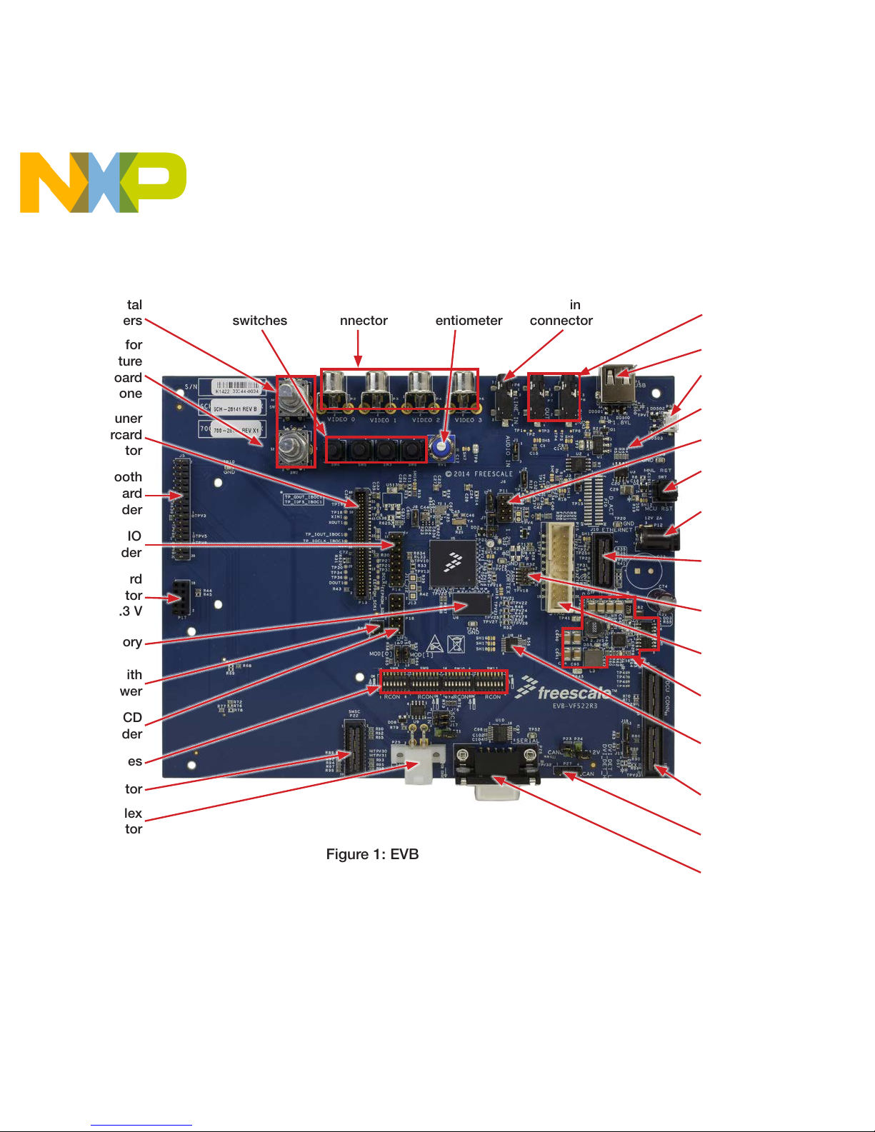
Get to Know the EVB-VF522R3 Board
Aux in
connector
Aux in
connector
Tuner
switches
ADC
potentiometer
Figure 1: EVB-VF522R3 top view
Hole for
miniature
on-board
microphone
Incremental
encoders
Radio tuner
daughtercard
connector
Bluetooth
daughtercard
header
I2C daughtercard
connector
with 3.3 V
I
2
C header with
5 V power
DDR3 memory
Generic CD
header
RCON switches
MLB connector
LIN Molex
connector
Digital GPIO
header
OTG Type AB USB
Type A host USB
2 headphone/
audio outputs
Hole for miniature
on-board microphone
Manual reset
push button
External power
connector
MAC (Ethernet
daughtercard
connector)
Cortex debug
connector
JTAG debug
connector
Peripheral resetcontrol multiplexer
Switch-mode
voltage regulator
DCU
daughtercard
connector
SCI (RS232)
connector
CAN header
Analog GPIO header
Page 5

5
freescale.com
Figure 2: EVB-VF522R3 bottom view
Switch-mode
voltage regulator
SD card
socket
Backup
battery
Miniature
on-board
microphone
3 x QuadSPI
flash memory
DSP IC
Miniature
on-board
microphone
2 audio DACs
Audio ADC
Page 6

6
Quick Start Guide
Step-by-Step Installation Instructions
This section describes how to use EVBVF522R3 and associated components.
Caution
Daughtercards are usually not hotswappable; ensure that the board is
powered OFF prior to fitting or removing a
daughtercard.
Download Software
and Tools
Download installation
software and documentation
under “Jump Start
Your Design” at
freescale.com/EVB-VF522R3
1
2
Configure the
Board
2.1 Insert SD Card
Insert the supplied SD card into the SD
card socket of EVB-VF522R3.
2.2 Set Up Boot Switches
Verify that the switches are set to boot
from the SD card per the Configuration
Settings mentioned on pages 8-10.
2.3 Optional: Connect Graphical Device
Attach a compatible Graphical Device:
• An LCD daughtercard, or
• An HDMI daughtercard (and connect it
to an HDMI monitor)
After boot-up, the kit SD card software
outputs the OS desktop through the DCU
daughtercard connector of EVB-VF522R3.
Page 7

7
freescale.com
Step-by-Step Installation Instructions
2.4 Connect RS232 Cable
Connect the RS232 cable to the serial
debug port of EVB-VF522R3. Support the
connector with one hand while plugging in
the cable to minimize flexing the board.
Serial port configuration:
• 115.2 kbaud
• 8 data bits
• 1 stop bit
• No parity
• No flow control.
2.5 Optional: Plug RF Tuner In
Plug the RF tuner (with its antenna plugged
in) into the dedicated EVB-VF522R3
on-board connector.
2.6 Connect Power Supply
Plug in the provided 12 V DC supply into
the power jack of EVB-VF522R3, followed
by plugging the AC cord into a wall outlet.
The power-indication LEDs of EVBVF522R3 illuminate when the system
powers up properly.
2.7 Use RF Tuner
Use the RF tuner with the RS232 user
interface, as well as the two incremental
encoders and four station-preset buttons.
2.8 Play Audio Files
• Plug a USB Flash drive with audio files
into the “Type A Host” USB connector.
• Plug headphones or active speakers into
the audio output (see Figure 1).
• Select and play an audio file using either
a touchscreen of the optional LCD with
incremental encoders, or the RS232
user interface.
Page 8

8
Quick Start Guide
EVB-VF522R3 Configuration Settings
The following is a list of the configuration settings on the EVB-VF522R3. The default
settings are shown in the gray boxes.
Device Function Setting Legend Description
J1
“AUDIO IN”
ADC routing
1–2 1 To MCU
2–3 3 To DSP
Removed ––– To none
J2
DSP mode
of operation
1–2 1 Slave (from MCU)
2–3 3
Master (from SPI
Serial Flash)
J3
DSP Flash
“Chip Enable”
control
1–2 1
By MCU (for DSP
Slave mode)
2–3 3
By DSP and DSP debug
header (for Master mode)
J4*
MCU
USB0 PHY
power source
1–2 1 Self–powered
2–3 3 Bus–powered (from P9)
Removed ––– Unpowered
J6
Optional 1.2 V
linear regulator
output control
Removed
–––
Enabled
Fitted Disabled
J7*
MCU USB1 PHY
power control
Fitted
–––
Powered
Removed Unpowered
J8
MCU VBAT
power source
1–2 1 From main MCU 3.3 V rail
2–3 3 From backup battery
Removed ––– Unpowered
Notes:
* Can be used for current measurements if replaced with a current measuring device.
** Can be used for current measurements if replaced with a current-sense resistor.
Page 9

9
freescale.com
EVB-VF522R3 Configuration Settings
Notes:
* Can be used for current measurements if replaced with a current measuring device.
** Can be used for current measurements if replaced with a current-sense resistor.
Device Function Setting Legend Description
J9*
Main 3.3 V power
for MCU
Fitted
–––
Provided
(Removed) (Not recommended)
J14, J15
MCU
Boot Mode
J15
(MOD[1])
J14
(MOD[0])
BOOTMOD
[1..0]
Boot Mode
1–2 (Low) 1–2 (Low) 00 Internal fuses
1–2 (Low) 2–3 (High) 01 Serial Download
2–3 (High) 1–2 (Low) 10 RCON switches
2–3 (High) 2–3 (High) 11 (Reserved)
J16, J17
Transceiver
selected
1–2 1/SCI SCI (RS232)
2–3 3/LIN LIN
Removed ––– None selected
J18, J19
Interface
selected
1–2 1 Touchscreen
2–3 3 I
2
C
Removed ––– None selected
P21
LIN interface power
source
Removed
–––
From Molex connector
Fitted Local
P23
CAN termination
control
Removed
–––
OFF
Fitted ON
P24
Power from EVB
over CAN cable
Removed
–––
OFF
Fitted ON
Page 10

10
Quick Start Guide
EVB-VF522R3 Configuration Settings
R28
MCU core ballast
transistor collector
voltage
A
–––
1.5 V
B 3.3 V
R79
LIN interface mode
of operation
Populated
–––
Master
Removed Slave
R621
MCU 24 MHz clock
source
A
–––
MCU crystal oscillator
B External oscillator IC
R625**
MCU
analog 1.2 V
power source
A
–––
From main MCU 1.2 V
power rail
B From linear 1.2 V regulator
R632**,
FB504**
MCU
analog 3.3 V
power source
FB504
–––
From main MCU 3.3 V
power rail
R632 From linear 3.3 V regulator
SW8
MCU RCON (reset
configuration)
12345678
12345678 12345678 12345678
ON
12345678 12345678 12345678 12345678
“RCON Switches” MCU
Boot Mode
(ignored in all other MCU
Boot Modes)
SW9
12345678
12345678 12345678
SW10
12345678
12345678
SW11
12345678
Notes:
* Can be used for current measurements if replaced with a current measuring device.
** Can be used for current measurements if replaced with a current-sense resistor.
Device Function Setting Legend Description
Page 11

11
freescale.com
EVB-VF522R3 Jumper Map
Default Jumper Setting
Page 12

For more information, visit
freescale.com/EVB-VF522R3 or
freescale.com/Vybrid
Freescale, the Freescale logo and Vybrid are trademarks of Freescale
Semiconductor, Inc., Reg. U.S. Pat. & Tm. Off. All other product or service
names are the property of their respective owners. ARM and Cortex are
registered trademarks of ARM Limited (or its subsidiaries) in the EU and/or
elsewhere. All rights reserved. © 2014 Freescale Semiconductor, Inc.
Doc Number: EVBVF522R3QSG REV 1 Agile Number: 926-28141 REV B
Support
Visit freescale.com/support for a list of phone
numbers within your region.
Warranty
Visit freescale.com/warranty for complete
warranty information.
Page 13

Mouser Electronics
Authorized Distributor
Click to View Pricing, Inventory, Delivery & Lifecycle Information:
NXP:
EVB-VF522R3
 Loading...