

Page 1

EXTERNAL USE
Ultra-Reliable MCUs for Industrial and Automotive Applications
www.nxp.com/DEVKIT-MPC5748G
DEVKIT-MPC5748G
QUICK START GUIDE (QSG)
Page 2

EXTERNAL USE
1
Contents
• Quick Start Package Overview
• Step-by-Step Installation Instructions
• Hardware: DEVKIT-MPC5748G Board
− Features
− Overview
− Pinout, Jumper and Peripherals Settings
• Software:
− Software Development Tools
− Pre-compiled Code Examples
• Documentation
• MPC574xG/C/B/D Family : Phantom Feature Differences
• OpenSDA
• Recommendations
Page 3
EXTERNAL USE
2
Quick Start Package Overview
Name Description
Quick Start Guide(QSG) Detailed description on availability of Hardware,Software and Documents to quick start with
MPC5748G project (this document)
Software Integration Guide(SWIG) Detailed walk through on how to install and useS32 Design Studio IDE for Power Architecture
Application Notes Detailed documents covering topics from ‘how to design hardware’ to ‘how to write software’
Fact Sheets, Reference Manuals and Data Sheets Detailed manuals for MPC5748G family of MCU and DEVKIT-MPC5748G board
Name Description
Integrated Development Environment (IDE) Eclipse based S32DS IDE with free GCC compiler and Debugger support
DEVKIT-MPC5748G Quick Start Package All in one package: Software examples and supporting documents for getting started
DEVKIT-MPC5748G Schematics PDF schematic files for the DEVKIT-MPC5748G board
DEVKIT-MPC5748G PCB Design Package Gerber files and Bill of Material
Downloads:
Documents:
Board:
DEVKIT-MPC5748G Low cost EVB with MPC5748G(176 LQFP-EP) Autoquality MCU on board
Page 4
EXTERNAL USE
3
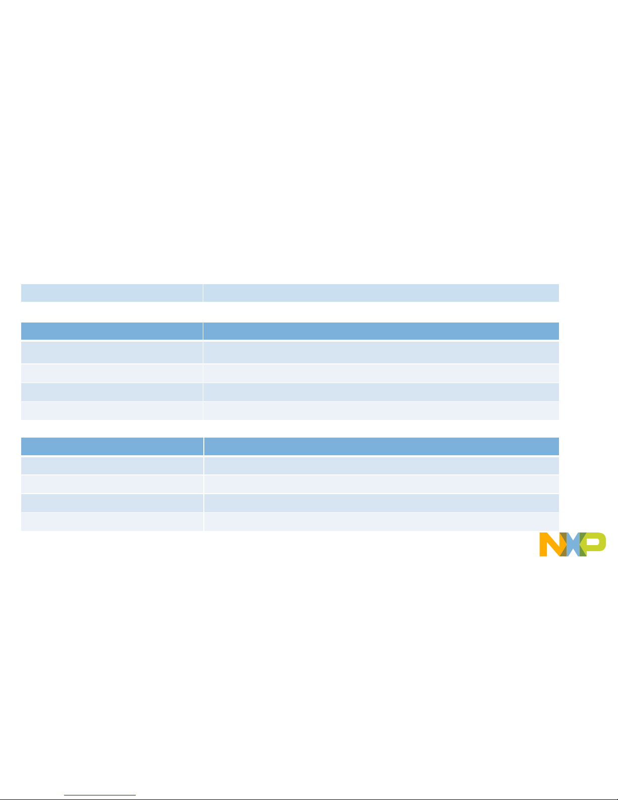
DEVKIT-MPC5748G Board : Features
• MPC5748G has 2 x 160 MHz Power Architecture® e200Z4 Dual issue
cores and 1 x 80 MHz Power Architecture® e200Z2 Single issue core
• MPC5748G qualified to AEC-Q100 Grade 1, ambient temperature of -40 to
+125 °C and suitable for ASIL-B/SIL2 applications
• Arduino™ UNO R3 footprint-compatible with expansion “shield” support
• Integrated Open-standard Serial and Debug Adapter (OpenSDA) with
support for several industry-standard debug interfaces as well as JTAG
connector
• Easy access to the MCU I/O header pins for prototyping
• On-chip connectivity for Ethernet, FlexRay, USB, SDHC, CAN, LIN,
UART/SCI and SPI
• MicroSD card slot for access to SDHC interface.
• Potentiometer for precise voltage and analog measurement
• 8 user LED
• 2 user push-button switches
• Flexible power supply options
• micro-B USB
• 12V External power supply
• Similar hardware across ARM
®
, S12 and Power Architecture®architecture
based MCUs
• DEVKIT-COMM shield boards for extended 4 CAN and 6 LIN ports
• Box includes:
− DEVKIT-MPC5748G Board
− USB Cable
• Downloads includes:
− Quick Start Package
− S32 Design Studio IDE
− Application notes
Page 5
EXTERNAL USE
4
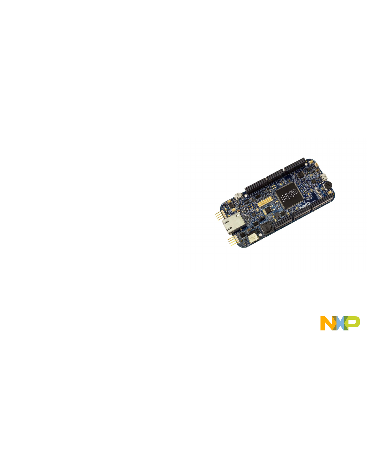
DEVKIT-MPC5748G Board : Revision D Update
Improvements
• Latest MPC5748G silicon used (mask set 0N78S).
• Added MicroSD connector for SDHC access.
• MicroUSB connector replaced with full-size connector for easier use with USB devices.
• Alternative placement of JTAG header and power supply jumper for easier access when using shields.
• User LEDs: DS4 changed to red, and DS5 changed to orange.
• Added pre-soldered pull resistor on CAN0 interface which can be can be added or removed with J16.
• Shorter array of female pin headers, allowing for smaller form factor.
Fixes
• Fixed issue with USB
The release of DEVKIT-MPC5748G Revision D brought several changes and improvements to the development board:
Page 6
EXTERNAL USE
5
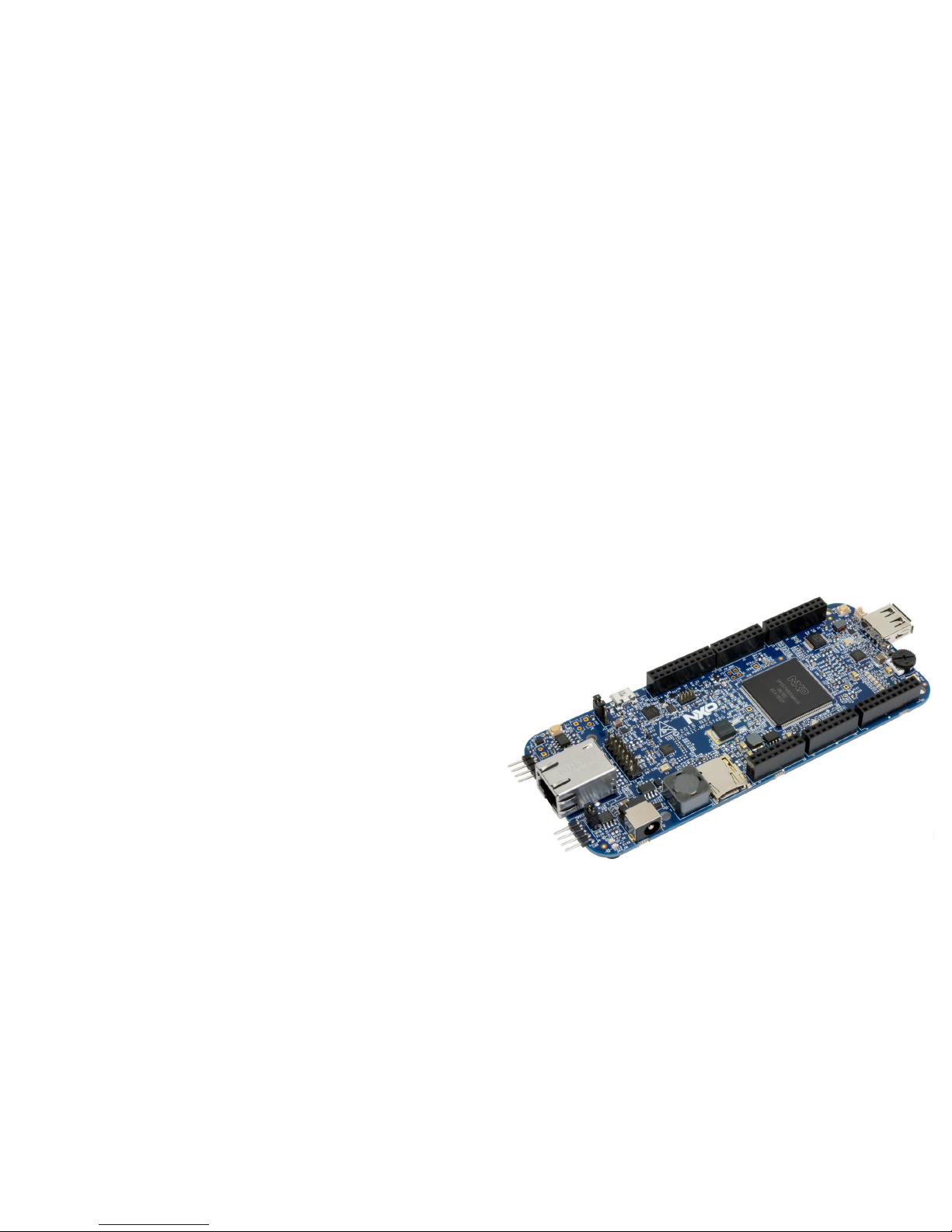
Step-by-Step Installation Instructions
1
Install Software and Tools
Install S32 Design Studio IDE for Power Architecture.
S32 Design Studio for Power
See Software Installation Guide (SWIG) for detailed procedure
2
Connect the USB Cable
Connect one end of the USB cable to the PC and the other end to
the micro-B connector on the DEVKIT-MPC5748G board. Allow the
PC to automatically configure the USB drivers.
3
Observe the Default Program reaction
The pre-loaded example project utilizes the DEVKIT-MPC5748G
user push button (SW2) and the user LEDs. Once the board is
plugged in, LEDs will blink in default pattern. Press push button to
switch between the two different patterns. Use Potentiometer to
change blinking speed. (Clock is configured to PLL running at 160
MHz)
4
Learn More About the DEVKIT-MPC5748G
Read release notes and documentation on the
nxp.com/DEVKIT-MPC5748G
nxp.com/MPC5748G
In this quick start guide, you will learn how to set up the
DEVKIT-MPC5748Gboard and run the default program.
J11
3 1
Jumper Setting:
2-3: USB powered
5V Supply, through
OpenSDA interface
Page 7
EXTERNAL USE
6
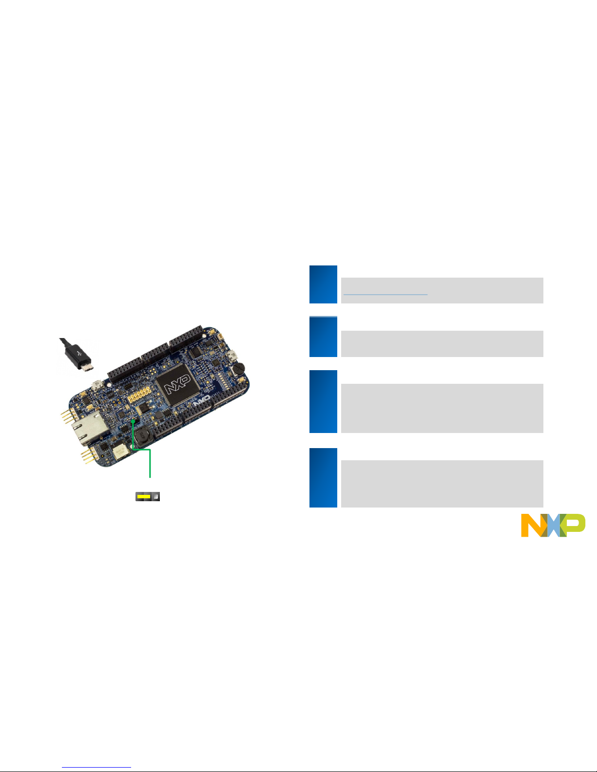
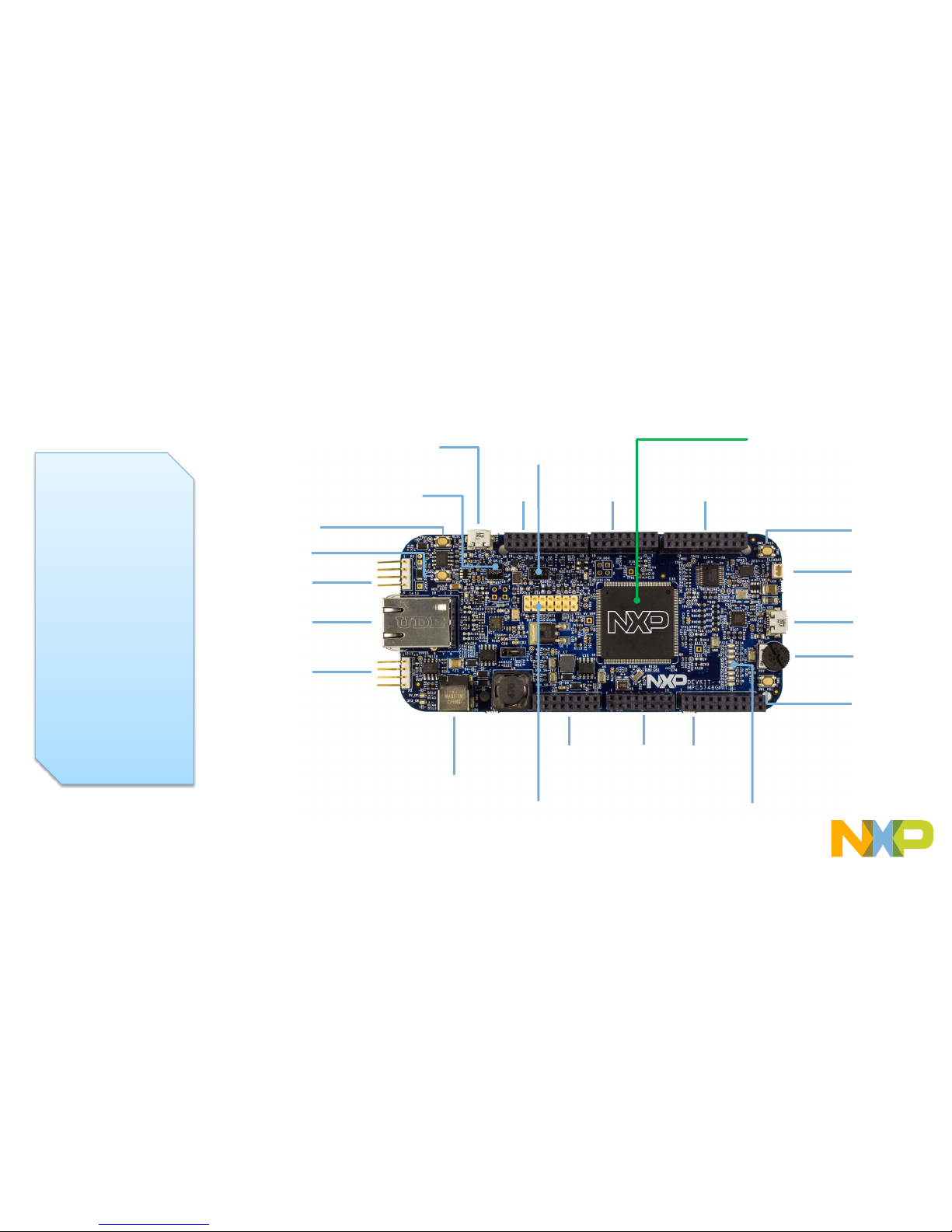
DEVKIT-MPC5748G Board Rev B : Overview
The DEVKIT-MPC5748G
is an ultra-low-cost
development platform for
MPC5748G
Microcontrollers.
Features include easy
access to all MCU I/Os, a
standard-based form
factor compatible with the
Arduino™ pin layout,
providing a broad range of
expansion board options,
and a USB serial port
interface for connection to
the IDE. The board has
option to be powered via
USB or an external power
supply.
NXP Microcontroller
MPC5748G (176 LQFP-EP)
JTAG
MPC5748G
JTAG
OpenSDA MCU
User LEDs
LIN Bus
CAN Bus
Ethernet
FlexRay
USB
Potentiometer
User Switch 2
User Switch 4
12V External
Power Supply
OpenSDA
micro-USB
J13 J14 J12
J3
J2
J4
OpenSDA
MCU
Reset Button
OpenSDA MCU
Boot Entry Button
Page 8

EXTERNAL USE
7
DEVKIT-MPC5748G Board Rev D : Overview
The DEVKIT-MPC5748G
is an ultra-low-cost
development platform for
MPC5748G
Microcontrollers.
Features include easy
access to all MCU I/Os, a
standard-based form
factor compatible with the
Arduino™ pin layout,
providing a broad range of
expansion board options,
and a USB serial port
interface for connection to
the IDE. The board has
option to be powered via
USB or an external power
supply.
NXP Microcontroller
MPC5748G (176 LQFP-EP)
JTAG
MPC5748G
JTAG
OpenSDA MCU
User LEDs
LIN Bus
CAN Bus
Ethernet
FlexRay
USB
Potentiometer
User Switch 2
User Switch 4
12V External
Power Supply
OpenSDA
micro-USB
J13 J14
J12
J3
J2
J4
OpenSDA
MCU
Reset Button
OpenSDA MCU
Boot Entry Button
MicroSD card
slot
Page 9

EXTERNAL USE
8
DEVKIT-MPC5748G Board : Pinout 1 of 3
Arduino Compatibility
The internal rows of the I/O headers on
the DEVKIT-MPC5748G are arranged to
fulfill Arduino™ shields compatibility .
J3
J2
FUNCTION PORT PIN PIN PORT FUNCTION
PB15 J2-15 J2-16 PE13
Timer
PB14 J2-13 J2-14 PF15
Timer
PB13 J2-11 J2-12 PE11
PB12 J2-09 J2-10 PE10
Timer
PB11 J2-07 J2-08 PE9
PB10 J2-05 J2-06 PE8
LIN4TX(UART)
PA5 J2-03 J2-04 PE7
LIN4RX
(UART) PA6 J2-01 J2-02 PE6
FUNCTION PORT PIN PIN PORT FUNCTION
SCL1
PI1 J3-19 J3-20 PG9
SDA1
PI0 J3-17 J3-18 PG8
NC J3-15 J3-16 PG7
GND J3-13 J3-14 PG6
SCLK_4
PF2 J3-11 J3-12 PI7
SIN_4
PF1 J3-09 J3-10 PI6
SOUT_4
PF0 J3-07 J3-08 PA15
SS_4
PF3 J3-05 J3-06 PA14
Timer
PA2 J3-03 J3-04 PA13
PA1 J3-01 J3-02 PA12
J3
J2
Page 10

EXTERNAL USE
9
DEVKIT-MPC5748G Board : Pinout 1 of 3
Arduino Compatibility
The internal rows of the I/O headers on
the DEVKIT-MPC5748G are arranged to
fulfill Arduino™ shields compatibility .
J13
J14
FUNCTION PORT PIN PIN PORT FUNCTION
PF11 J13-02
J13-01
VIN
12V
PF10 J13-04
J13-03
PER_HVA
PF6 J13-06
J13-05
RESET
MPC5748G Reset
PF4 J13-08
J13-07
3V3_SR
3.3V
PF5 J13-10 J13-9 5V0_SR
5V
PF7 J13-12
J13-11
GND
PF8 J13-14
J13-13
GND
PF9 J13-16
J13-15
VIN
12V
FUNCTION PORT PIN PIN PORT FUNCTION
PB4 J14-02
J14-01
PG13
ADC1_S[1]
PB5 J14-04
J14-03
PG12
ADC1_S[2]
PB6 J14-06
J14-05
PI8
ADC0_S[16]
PB7 J14-08
J14-07
PI11
ADC0_S[19]
PD0 J14-10 J14-9 PI12
ADC0_S[20]
PD1 J14-12
J14-11
PI13
ADC0_S[21]
PD2 J14-14
J14-13
PI14
ADC0_S[22]
PD3 J14-16
J14-15
PI15
ADC0_S[23]
J13
J14
Page 11

EXTERNAL USE
10
DEVKIT-MPC5748G Board : Pinout 3 of 3
Arduino Compatibility
The internal rows of the I/O headers on
the DEVKIT-MPC5748G are arranged to
fulfill Arduino™ shields compatibility .
J12
J4
FUNCTION PORT PIN PIN PORT FUNCTION
PF12 J4-19 J4-20 PE5
PF13 J4-17 J4-18 PE4
PC6 J4-15 J4-16 PE0
PC7 J4-13 J4-14 PE1
PI2 J4-11 J4-12 GND
PI3 J4-09 J4-10
PER_HVA
PH3 J4-07 J4-08 PC11
PH4 J4-05 J4-06 PC10
PG3 J4-03 J4-04 PG5
PG2 J4-01 J4-02 PG4
FUNCTION PORT PIN PIN PORT FUNCTION
PD12 J12-2 J12-1 PD15
PD10 J12-4 J12-3 PD14
PD9 J12-6 J12-5 PD13
PD8 J12-8 J12-7 PH8
PER_HVA
J12-10 J12-9 PH7
GND J12-12
J12-11
PH6
PD7 J12-14
J12-13
PJ3
PD6 J12-16
J12-15
PJ2
PD5 J12-18
J12-17
PJ1
PD4 J12-20
J12-19
PJ0
J4
J12
Page 12

EXTERNAL USE
11
DEVKIT-MPC5748G Board : Jumper Settings
J11
There is only one jumper: J11
It is to select Power source:
1-2: Default External 12 V Supply
2-3: USB powered 5V Supply, through
OpenSDA interface
3 1
Note: For high power/current consuming applications (like
using external shield boards) use “External 12 V Supply” only
Rev D
Rev B
Page 13

EXTERNAL USE
12
DEVKIT-MPC5748G Board : Communication Interfaces 1 of 2
LIN
CAN
FlexRay
LIN_0
DESCRIPTION
NAME
PIN
GND
P3-01
GND
P3-02
Connect to
12V
VBAT
P3-03
Port PB2
& PB3
LIN
P3-04
CAN_0
DESCRIPTION NAME PIN
Port PB0 & PB1
CANH
P5-01
CANL
P5-02
NC
P5-03
GND
P5-04
FlexRay_A
DESCRIPTION
NAME PIN
FRA
-DATA-A P2_1
FRA
-DATA-B P2_2
FlexRay_A
DESCRIPTION
PORT
FR_A_TX
PC5
FR_A_TX_EN
PE2
FR_A_RX
PE3
Note: LIN Physical Interface require 12V supply on pin P3-03
CAN termination resistor jumper:
Open = No resistor
Closed = 120Ohm
(Rev D only)
Page 14

EXTERNAL USE
13
DEVKIT-MPC5748G Board : Communication Interfaces 2 of 2
Ethernet
USB
ETHERNET_0
DESCRIPTION PORT
RMII_0_TXD[0]
PH1
RMII_0_TXD[1]
PH0
RMII_0_TX_EN
PH2
RMII_0_RXD[0]
PA9
RMII_0_RXD[1]
PA8
RMII_0_RX_ER
PA11
RMII_0_RX_DV
PF15
RMII_0_MDC
PG0
RMII_0_MDIO
PF14
RMII_0_TX_CLK (Reference clock)
PG1
USB_1
DESCRIPTION PORT
ULPI1_D7
PH12
ULPI1_D6
PH11
ULPI1_D5
PG11
ULPI1_D4
PG10
ULPI1_D3
PE15
ULPI1_D2
PE14
ULPI1_D1
PG15
ULPI1_D0
PG14
ULPI1_STP
PI4
ULPI1_NXT
PI5
ULPI1_DIR
PC3
ULPI1_CLK
PC2
UART
UART_2 – LinFlex_2
OpenSDA micro-USB
DESCRIPTION
PORT
TX
PC8
RX
PC9
SDHC
SDHC
DESCRIPTION PORT
SDHC_DATA0
PI3
SDHC_DATA1
PI2
SDHC_DATA2
PI1
SDHC_DATA3
PI0
SDHC_CMD
PE6
SDHC_CLK
PE7
SDHC_CD
PA1
SDHC_WP
N/A for MicroSD
Page 15

EXTERNAL USE
14
DEVKIT-MPC5748G Board : User Peripherals
User
Switch 2
DESCRIPTION PIN PORT
Potentiometer (ADC0 CH9)
RV1/POT
PB4
User Switch 2
SW2
PE12
User Switch
4
SW4
PA3
User LEDs
DS4
PA10
DS5
PA7
DS6
PH13
DS7
PC4
DS8
PH5
DS9
PJ4
DS10
PA0
DS11
PA4
Reset Button
SW1
User
Switch 4
Potentiometer
User
LEDs
Reset
Button
Page 16

EXTERNAL USE
15
DEVKIT-MPC5748G Board : Programing Interface
OpenSDA Interface
DESCRIPTION PIN
OpenSDA MCU Boot Entry
SW3
OpenSDA micro USB:
On-board JTAG connection via
open source
OSBDM circuit using the
MC9S08JM60
Microcontroller
J1
OpenSDA JTAG
:
JTAG to update firmware in
OpenSDA MCU
J6
OpenSDA JTAG
JTAG
OpenSDA micro USB
OpenSDA MCU
Boot Entry Button
JTAG
DESCRIPTION PIN
Support for USB Multilink
Interface
P4
Page 17

EXTERNAL USE
16
Software Development Tools
• IDE & Compilers
− Free S32 Design Studio IDE for Power Architecture with GCC compiler
− GHS MULTI Integrated Development Environment
− Cosmic IDE
− iSystems winIDEA IDE
− Sourcery
TM
CodeBench Development Tools
• Debuggers
− Free OpenSDA debugger on board and supported by S32DS IDE
− P&E USB Multilink
− iSystems iC6000
− Lauterbach TRACE32 JTAG Debugger
Page 18

EXTERNAL USE
17
Pre-Compiled Code Examples
• Pre-compiled example projects are
available in S32DS as well as on
nxp.com/DEVKIT-MPC5748G for quick
start
• Example projects also includes the
projects from Application Note, AN4830:
Qorivva Recipes for MPC574xG
List of code examples:
1. Hello
2. Hello+pll
3. Hello+pll+interrupts
4. eDMA+ PBridge
5. Semaphores
6. Register Protection
7. Low Power: STOP mode
8. Analog-to-digital
Converter
9. Timed I/O (eMIOS)
10. CAN
11. CAN+DMA
12. LIN
13. UART
14. SPI
15. SPI+DMA
16. I2C
17. Ethernet
18. Body Cross Trigger
Unit (BCTU)
19. System Memory
Protection Unit
(SMPU)
20. Flash
Page 19

EXTERNAL USE
18
Documentation
General Documents
• MPC5748G Microcontroller Data Sheet
• MPC5748G Microcontroller Reference Manual
• MPC5748G Microcontroller Fact Sheet
• DEVKIT-MPC5748G Board Fact Sheet
• Software Integration Guide (SWIG)
Application Notes
• AN4830: Qorivva Recipes for MPC574xG
• AN5220: MPC5748G Hardware Design Guidelines
• AN5114: Migrating between MPC5748G and MPC5746C
• AN4868: EEPROM Emulation with NXP MPC55xx, MPC56xx, and MPC57xx Microcontrollers
• AN4805: A Practical Approach to Hardware Semaphores
Page 20

EXTERNAL USE
19
MPC574xG/C/B/D Family : Phantom Feature Differences
Flash/RAM
Package
100MAPBGA
(11x11mm, 1mm)
176LQFP-EP
(24x24mm, 0.5mm)
256MAPBGA
(17x17mm, 1mm)
324MAPBGA
(19x19mm, 1mm)
6M/768k
6M/768k
SPC5748G
SPC5748C
SPC5748G
SPC5748C
SPC5748G
SPC5748C
4M/768k
4M/512k
SPC5747G
SPC5747C
SPC5747G
SPC5747C
SPC5747G
SPC5747C
3M/768k
SPC5746G SPC5746G SPC5746G
3M/384k (512k optional)
3M/384k (512k optional)
SPC5746C
SPC5746B
SPC5746C
SPC5746B
SPC5746C
SPC5746B
PPC5746C
2M/256k
2M/256k
SPC5745C
SPC5745B
SPC5745C
SPC5745B
SPC5745C
SPC5745B
1.5M/192k
1.5M/192k
SPC5744C
SPC5744B
SPC5744C
SPC5744B
SPC5744C
SPC5744B
Color Coding:
Triple Core, Ethernet, FlexRay, USB, SDHC,
(optional HSM, 2nd Ethernet + switch)
Dual Core, Ethernet, FlexRay
(all: optional HSM, 5747C/5748C: 2nd
Ethernet + switch)
Single Core, FlexRay, Ethernet (optional
HSM)
Debug device for SPC5745B/C and
SPC5746B/C
- not for production
Page 21

EXTERNAL USE
20
OpenSDA 1 of 2
• OpenSDA is an open-standard serial and debug adapter
• It bridges serial and debug communications between a USB host and an embedded target processor
• DEVKIT-MPC5748G comes with the OpenSDA Application preinstalled
• Follow these instructions to run the OpenSDA Bootloader and update or change the installed OpenSDA Application
Enter OpenSDA Bootloader Mode
1. Unplug the OpenSDA USB cable if attached
2. Press and hold the Reset button (SW3)
3. Plug in a USB cable between a USB host and the OpenSDA USB
connector (labeled “SDA”)
4. Release the Reset button
A removable drive should now be visible in the host file system with a
volume label of BOOTLOADER. You are now in OpenSDA Bootloader
mode.
IMPORTANT NOTE: Follow the “Load an OpenSDA
Application” instructions to update the application on your
MK20DX128VFM5 to the latest version. It is likely that the version
provided in this package is newer than what was preprogrammed on your
MK20DX128VFM5.
Load an OpenSDA Application
1. While in OpenSDA Bootloader mode, double-click SDA_INFO.HTML in the
BOOTLOADER drive. A web browser will open the OpenSDA homepage
containing the name and version of the installed Application. This
information can also be read as text directly from SDA_INFO.HTML
2. ***********************Download Application**************************
3. Locate the OpenSDA Applications folder
4. Copy & paste or drag & drop the Application to the BOOTLOADER drive
5. Unplug the USB cable and plug it in again. The new OpenSDA Application
should now be running and check the latest version by repeating Step-1
Use the same procedure to load other OpenSDA Applications.
Page 22

EXTERNAL USE
21
OpenSDA 2 of 2
Using the Virtual Serial Port
1. Determine the symbolic name assigned to the DEVKIT-MPC5748G virtual serial port. On Windows platform open Device Manager and look for the COM
port named “OpenSDA-CDC Serial Port”.
2. Open the serial terminal emulation program of your choice. Examples for Windows platform include Tera Term, PuTTY, or HyperTerminal.
3. Program one of the “code examples” using S32 Design Studio IDE.
4. Configure the terminal emulation program. Most embedded examples use 8 data bits, no parity bits, and one stop bit (8-N-1). Match the baud rate to the
selected serial test application and open the port.
5. Press and release the Reset button (SW1) at anytime to restart the example application. Resetting the embedded application will not affect the
connection of the virtual serial port to the terminal program.
NOTE: Refer to the OpenSDA User’s Guide for a description of a known Windows issue when disconnecting a virtual serial port while the COM port is in
use.
Page 23

EXTERNAL USE
22
Recommendations
• For high power/current consuming applications (like using external shield boards) use “External 12 V Supply” only.
• External 12 V Supply Specifications
− Fully regulated Switching Power Supply
− Input Voltage: 100-240V AC 50/60Hz
− Output: 12V 1A/2A DC
− Plug size: 5.5mm x 2.1 mm, Center Positive
• By default “New Project” in S32 Design Studio IDE makes application to run at 16 MHz Internal RC (IRC) oscillator. For faster performance, configure PLL to desired
frequency and switch clock source to PLL before executing application code.
• For faster debugging, debug from RAM, because this cuts down the lengthy Flash erase operation cycles. Follow the Software Integration Guide (SWIG) for details.
• Keep S32 Design Studio IDE and OpenSDA firmware Up-to-date for best results.
• Post Technical Questions on NXP community for MPC5xxx.
• Useful Links:
− nxp.com/mpc5748g
− nxp.com/devkit-mpc5748g
− nxp.com/s32ds
− nxp.com/community
 Loading...