

Page 1
AN12306
A71CL Quick start guide for A71CLARD-BAI and Kinetis
Rev. 1.0 — 14 December 2018
515910
Application note
COMPANY PUBLIC
Document information
Info
Content
Keywords
Security IC, A71CL, A71CLARD-BAI, FRDM-K64F
Abstract
This document helps getting st arted with A71CLARD-BAI and the FRDM-
K64F development platforms for K64 MCUs.
Page 2
NXP Semiconductors
AN12306
A71CL Quick start guide for A7 1 CLARD-BAI and Kinetis
515910
All information provided in this document is subject to legal disclaimers.
© NXP B.V. 2018. All rights reserved.
Application note
COMPANY PUBLIC
Rev. 1.0 — 14 December 2018
515910
2 of 32
Contact information
For more information, please visit:
http://www.nxp.com
Revision history
Rev
Date
Description
1.0
20181214
First release
Page 3
NXP Semiconductors
AN12306
A71CL Quick start guide for A7 1 CLARD-BAI and Kinetis
515910
All information provided in this document is subject to legal disclaimers.
© NXP B.V. 2018. All rights reserved.
Application note
COMPANY PUBLIC
Rev. 1.0 — 14 December 2018
515910
3 of 32
Introduction
This document explains how to get started with the A 71CLARD-BAI development kit and
the FRDM-K64F development platforms for K64 MCUs. This guide provides an o verview
of the hardware used, followed by detailed instructi ons for setting up the software
development environment. Finally, it describes how to run an MCU example doing crypto
on the secure element using FRDM-K64F acting as the platform host MCU.
A71CL Overview
The A71CL-BAI is a ready-to-use solution, enabling ease-of-use security for IoT device
makers to connect to Baidu Cloud. It is a secure element capable of securely storing and
provisioning credentials and is already pre-provisioned with Baidu credentials. It is based
on A71 secure element hardware which runs an application which manages the
credentials.
The A71CL-BAI solution provides basic security measures protecting the IC against
many physical and logical attacks. It can be integrat ed with various host platforms and
operating systems to secure a broad range of applications.
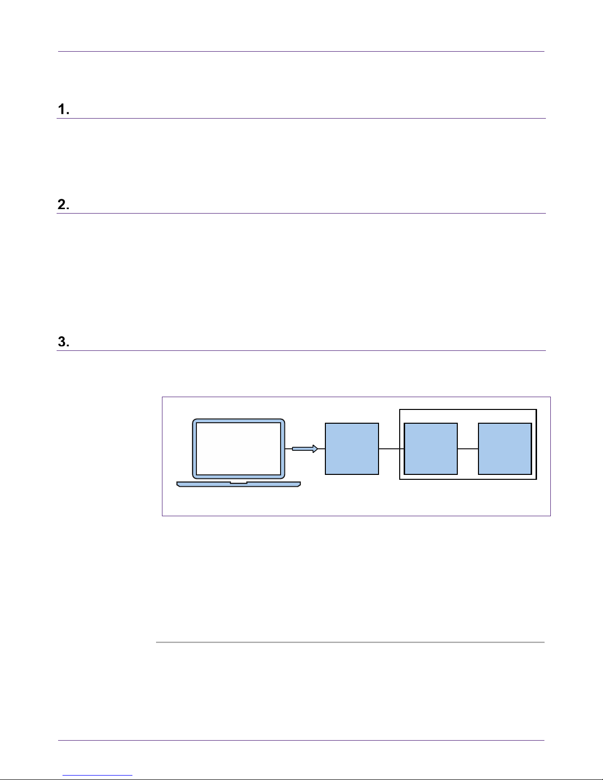
System description
The A71CL evaluation setup presented in this document consists of an A71CL security
IC connected to the FRDM-K64F development pl at form through the A71CLARD-BAI
Arduino compatible kit.
Fig 1. System architecture diagram
This getting-started guide is divided in three parts:
• Hardware overview and setup: It describes the FRDM-K64F dev elopment platform
and the A71CL Arduino compatible kit (A71CLARD-BAI) as well as how to mount
them together.
• Software setup: It describes how to configure the devel opm ent environment and
how to import the required software packages.
• A71CL application examples execution: It describes ho w to run the A71CL
application examples contained in the A71CL-Baidu Host software package.
aaa-032573
development PC
kinetis board
HOST MCU
A71CLARD-ALI
I2C
ARDUINO
INTERFACE
BOARD
A71CL-
ALI
USB
I2C
Page 4
NXP Semiconductors
AN12306
A71CL Quick start guide for A7 1 CLARD-BAI and Kinetis
515910
All information provided in this document is subject to legal disclaimers.
© NXP B.V. 2018. All rights reserved.
Application note
COMPANY PUBLIC
Rev. 1.0 — 14 December 2018
515910
4 of 32
Note: From now on, the term ‘Kinetis board’ will be used in this guide to avoid
redundancy and to improve readability. ‘Kinetis boa rd’ refers to the FRDM-K64F.
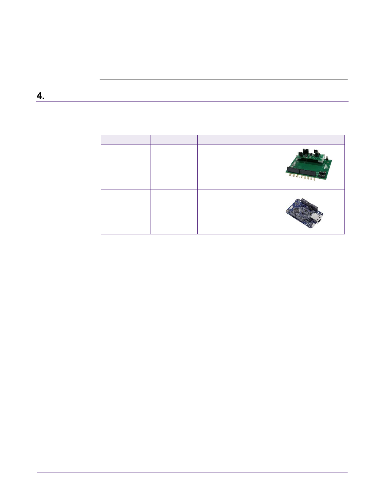
Hardware overview
This setup uses a Kinetis board as a host MCU while the A71CL security IC acts as t h e
secure element. The following two boards are needed:
Table 1. Needed Boards
Item
Type / 12NC
Content
Arduino
Development Kit
A71CLARD-BAI
9353 763 89598
(only available
through NXP
sales contact)
Arduino Adapter Board +
MiniPCB containing a A71CL
secure element IC preprovisioned for Baidu Cloud:
A7101CLTK2/T0BC27F,
12NC: 9353 725 76118
MCU-Board
FRDM-K64F
9353 262 93598
K64F Freedom MCU-
Development board
4.1 A71CL Arduino compatible development kit (A71CLARD)
The A71CLARD is an Arduino development kit cont ai ning t wo items as well as:
1. An A71CL Mini PCB board
2. An Arduino interface board, allowing the user to connect the A71CL to any host
featuring an Arduino compatible header (e.g., many LP C, K i netis and i.MX boards in
the industry).
4.1.1 A71 Mini PCB board
The Mini PCB board is a small PCB containing the A71 solution and a set of jumpers for
the I
2
C host interface selection.
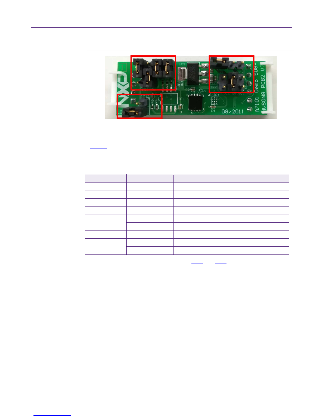
Fig 2 shows an image of the MiniPCB. It features two connectors that can be used
depending on the communication interface employed. The figure shows the jumpers
configuration that enables the use of the A71 I
2
C interface.
Page 5
NXP Semiconductors
AN12306
A71CL Quick start guide for A7 1 CLARD-BAI and Kinetis
515910
All information provided in this document is subject to legal disclaimers.
© NXP B.V. 2018. All rights reserved.
Application note
COMPANY PUBLIC
Rev. 1.0 — 14 December 2018
515910
5 of 32
Fig 2. A71 mini PCB
To enable the I2C communication protocol, it is necessary to configure JP5/6 according
to Table 2
. JP2 connects the A71 to the on-board 3.3V voltage regulator on the MiniPCB
board. The jumpers JP3 and JP4 enable the I²C SDA/ S CL pul l-up resistors. JP7 can be
used to connect the A71 reset signal.
Table 2. Default MiniPCB Jumper settings
Jumper
Setting
Usage
JP1
Not set
External VCC connection
JP2
3-4
Connect A71 to 3.3V regulator on MiniPCB
JP3
Set
Connect I²C SDA pull-up resistor
JP4
Set
Connect I²C SCL pull-up resistor
JP5
1-2
Use I²C address 0x92/0x93
2-3 (Default)
Use I²C address 0x90/0x91
JP6
1-2
Activate I²C interface
JP7
Not set (Default)
A71 operates
Set
A71 IC reset
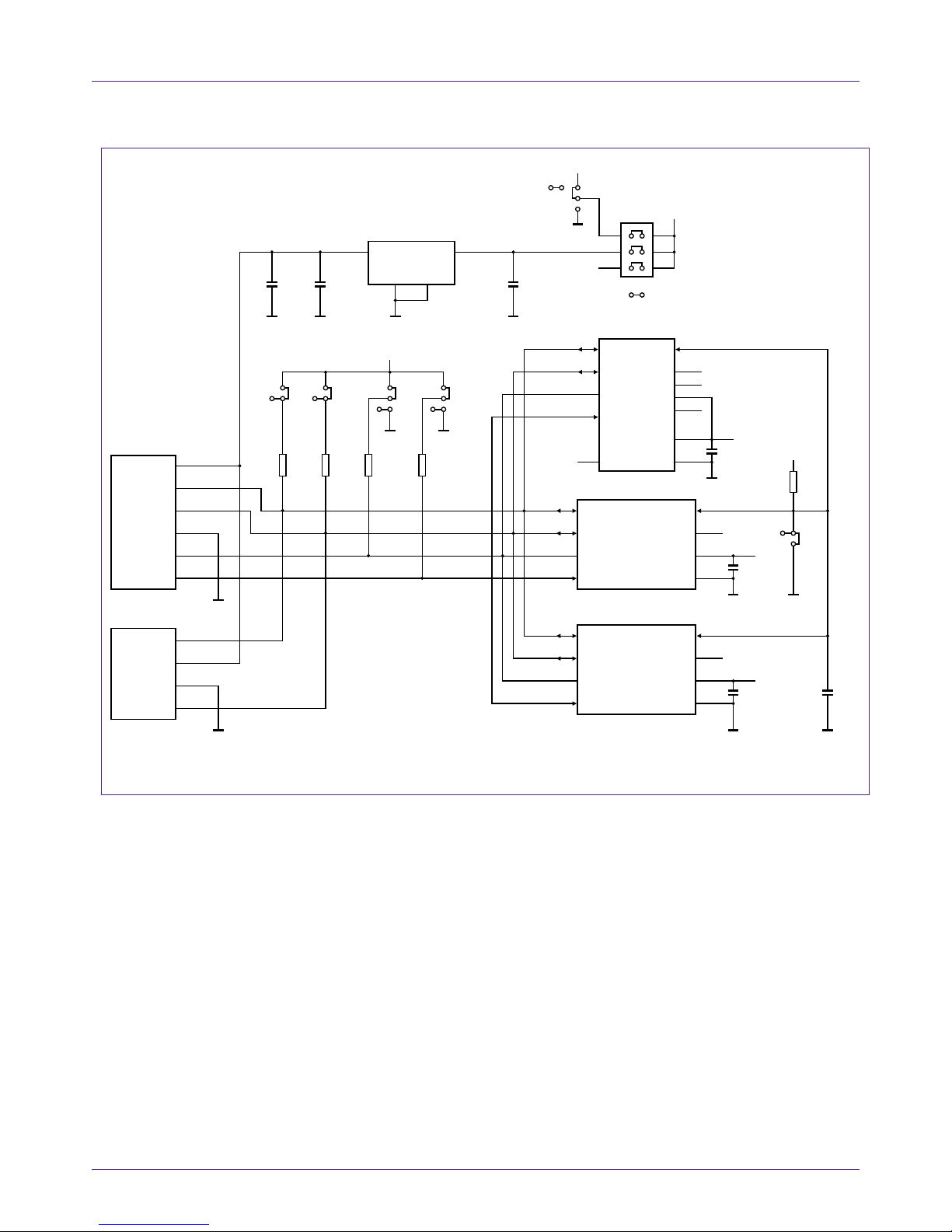
The board schematic and layout are shown in Fig 3 and Fig 4.
Page 6
NXP Semiconductors
AN12306
A71CL Quick start guide for A7 1 CLARD-BAI and Kinetis
515910
All information provided in this document is subject to legal disclaimers.
© NXP B.V. 2018. All rights reserved.
Application note
COMPANY PUBLIC
Rev. 1.0 — 14 December 2018
515910
6 of 32
Fig 3. A71 Mini PCB board schematic
aaa-032574
VSS
C2
100 nF
GND
GND
GND
GND
GND
C7
n.c.
100 nF
GND
IC2
nc/A7101 HVSON8_SOT909-1
VCC
VCC
n.c.
nRSTSDA
SCL
IF1
IF0
2
7
4
6
3
5
1
8
VSS
C1
100 nF
R5
100 kΩ
GND GND
IC1
A7101
SO8_SOT96-1
VCC
VCC
VCC
n.c.
nRSTSDA
SCL
IF1
IF0
5
4
2
3
IF0
P2
Molex
38-00-1336
IF1
GND
SCL
1
2
3
4
SDA
5
VCC +5 V
6
SCL
P1
Molex
38-00
-1334
VCC +5 V
GND
SDA
1
2
3
4
1
8
6
7
VSS
C4
100 nF
GND
IC4
JP2
VCC selec t
VCC
VCC_ext
nc/A7101 WLCSP
VCC
VCC
n.c.
nRSTSDA
SCL
IF1
IF0
A2
B2
A1
n.c.
B1
n.c.
C1
n.c.
B3
C3
C4
TP
C2
B4
A3
A4
IC3
TDA3663
31
2 4
VP REG+5
V
+3.3 V
C
5
10
µF
GND
GND
GNDGND
C3
100 nF
JS5
VCC
JP5
CLK
GND
C6
10 µF
JS2
5
3
GND
JP1
VCC ext .
GND
JS6
JP6
nSS
JS4
JP4
JS3
JP3
R1
3.3 kΩR23.3 kΩR31.0 kΩ
R4
1.0 kΩ
JS7
JP7
1
6
4
2
JS1
Page 7
NXP Semiconductors
AN12306
A71CL Quick start guide for A7 1 CLARD-BAI and Kinetis
515910
All information provided in this document is subject to legal disclaimers.
© NXP B.V. 2018. All rights reserved.
Application note
COMPANY PUBLIC
Rev. 1.0 — 14 December 2018
515910
7 of 32
Fig 4. A71 Mini PCB board silkscreen with def ault jumper positions marked black
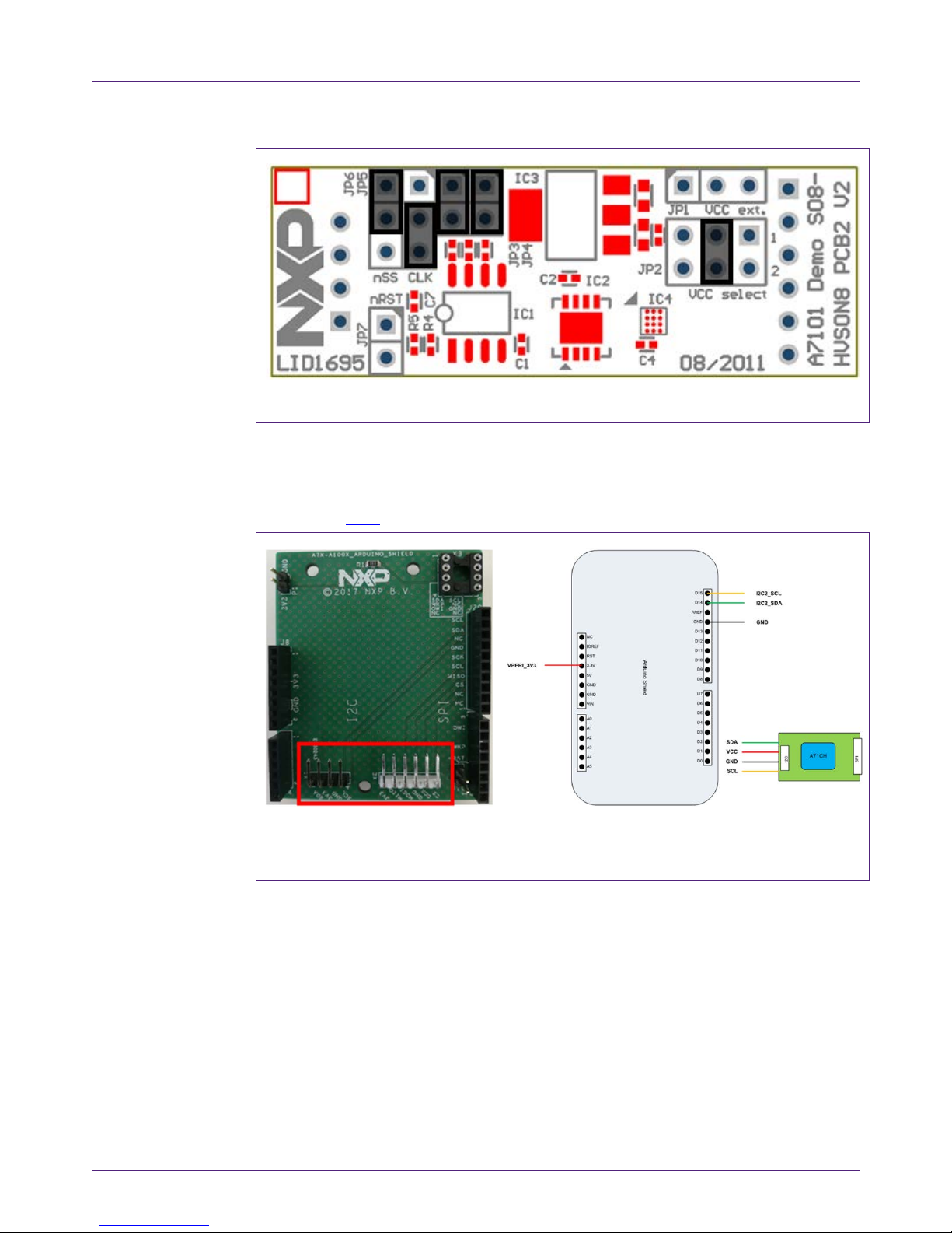
4.1.2 Arduino interface board
The Arduino header board permits the user to inte rf ace the A71 Mini PCB with the
Kinetis board. Fig 5
shows the board pinout.
(1) Connection from the perspective of a matching Arduino Shield (top view)
Fig 5. A71 Arduino header
4.2 Freedom development platforms for Kinetis
The section details the Freedom development platforms for Kinetis supported by the
A71CL product support package.
4.2.1 FRDM-K64F
The Kinetis FRDM-K64F [FRDM_K64F] [6] development platform i s a simple, yet
sophisticated design, featuring a Kinetis K64 series microcontroller, built on the ARM®
Cortex®-M4 core. The FRDM-K64F can be used to evaluate the K64, K63, and K 24
Kinetis K series devices. It features the MK64FN1M 0VLL12 MCU, which boasts the
Page 8
NXP Semiconductors
AN12306
A71CL Quick start guide for A7 1 CLARD-BAI and Kinetis
515910
All information provided in this document is subject to legal disclaimers.
© NXP B.V. 2018. All rights reserved.
Application note
COMPANY PUBLIC
Rev. 1.0 — 14 December 2018
515910
8 of 32
maximum operation frequency of 120 MHz, 1 MB of flash, 256 KB RAM, a full-speed
USB controller, Ethernet controller, secure digi tal host controller, and analog and digital
peripherals.
The FRDM-K64F hardware is form-factor compatibl e with the Arduino R3 pin layout,
providing a broad range of expansion board options. The onboard interface includes a
six-axis digital accelerometer & magnetometer, RGB LED, SDHC, add-on Bluetooth
module, add-on RF module, Ethernet and OpenSDAv2, the NXP open-source hardware
embedded serial and debug adapter running an open-source bootloader.
Fig 6. FRDM-K64F Freedo m development platform for Kinet is K64, K63 and K24 MCUs
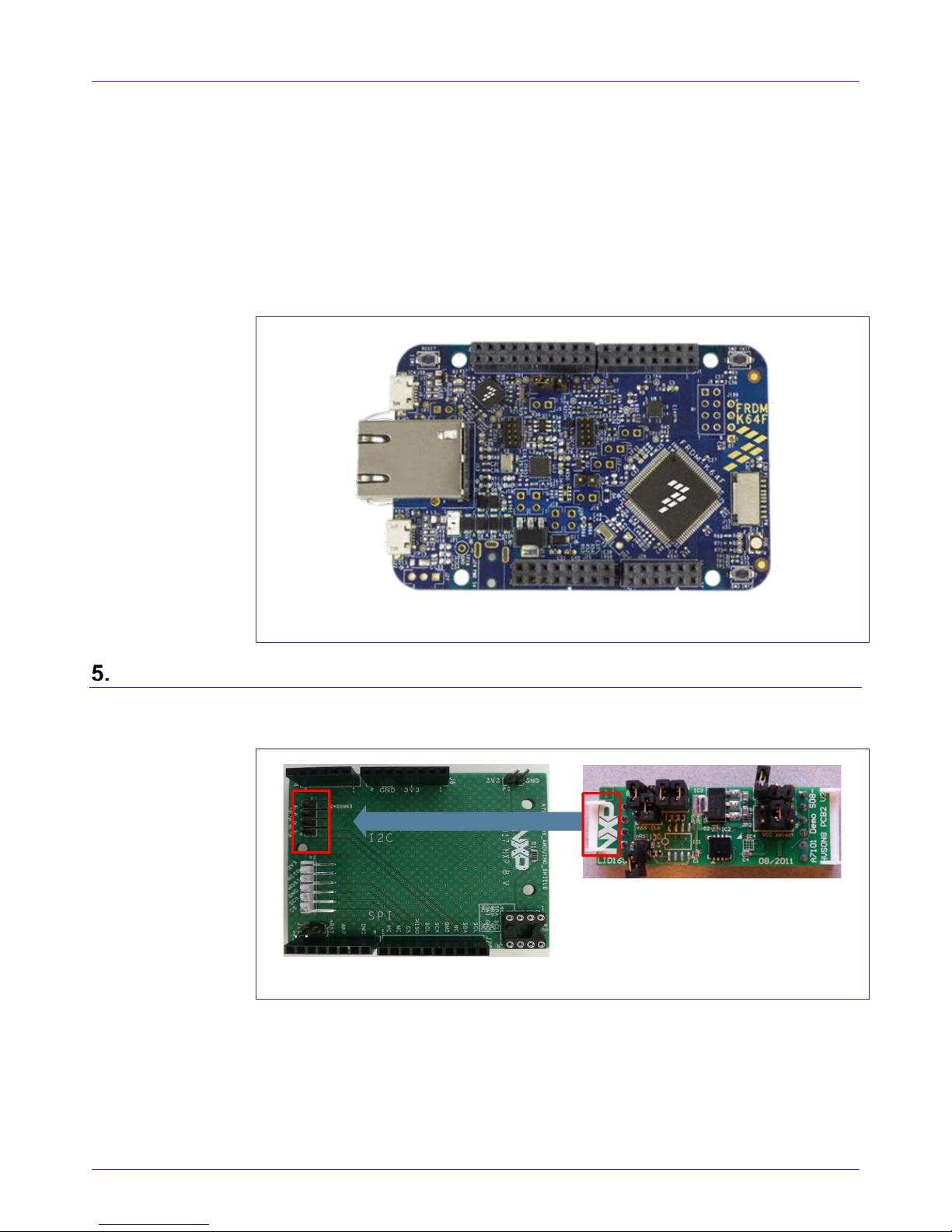
Hardware setup
The hardware setup consists of mounting the different boards together.
First, plug the A71 Mini PCB board to the I2C plug of the Arduino interface board.
Fig 7. A71 Mini PCB board mounting on the I2C adaptor of the Arduino interface board
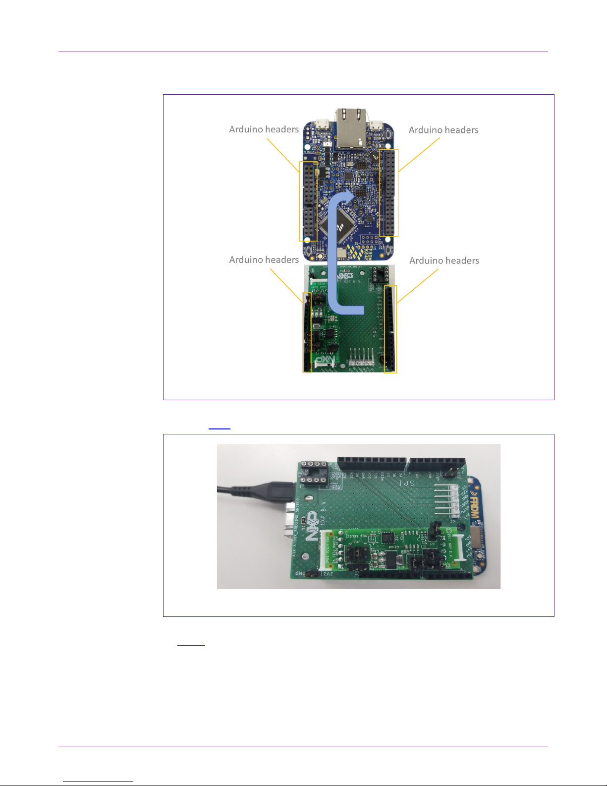
Second, plug the A71CL into the Kinetis board using t he Arduino adaptors. The Arduino
shield board comes with male connectors below and f em al e connectors on top.
Page 9
NXP Semiconductors
AN12306
A71CL Quick start guide for A7 1 CLARD-BAI and Kinetis
515910
All information provided in this document is subject to legal disclaimers.
© NXP B.V. 2018. All rights reserved.
Application note
COMPANY PUBLIC
Rev. 1.0 — 14 December 2018
515910
9 of 32
Fig 8. A71 Arduino kit mounted on Kinetis FRDM-K64F board
Then, the A71 security IC is connected to the Kinetis board through the Arduino i nt erf ace
board. See Fig 9
.
Fig 9. Arduino interface board connected to the Kinetis board (FRDM-K64F)
As can be observed, there are two USB connectors in the Ki netis boards FRDM-K64F.
See Fig 10
. The USB connector highlighted in red corresponds to OpenSDA debug port.
This port will be used by the development PC to flash and deb ug the A71 examples over
an on-board debugger into the Kinetis MCU as well as to have a serial console. The USB
Page 10

NXP Semiconductors
AN12306
A71CL Quick start guide for A7 1 CLARD-BAI and Kinetis
515910
All information provided in this document is subject to legal disclaimers.
© NXP B.V. 2018. All rights reserved.
Application note
COMPANY PUBLIC
Rev. 1.0 — 14 December 2018
515910
10 of 32
connector highlighted in yellow is directly connected to the K64F MCU and functionality
depends on the example programmed into the MCU.
Fig 10. Red USB indicates OpenSDA debug port. Yellow USB indicates K64F port
(FRDM-K64F)
Software setup
This section details the required steps to complete t he sof t ware setup for A71 security IC
and FRDM-K64F Freedom development platforms. The f ol lowing items are needed:
• MCUxpresso IDE, see section 6.1
. Here we use version 10.2.
• Kinetis SDK for MCUxpresso, see section 6.2. Here we use version 2.4.
• Hostlibrary code examples installation and importing, see sections 6.3 and 6.4.
• Serial terminal application, see section 6.5.
• OpenSDA debugger firmware update on Kinetis board, see section 6.6.
6.1 MCUXpresso IDE installation
MCUXpresso IDE is a fully featured software development environment for NXP’s ARMbased MCUs, and includes all the tools necessary to develop high-quality embedded
software applications in a timely and cost-effecti ve fashion.
MCUXpresso IDE is based on the Eclipse IDE and includes the industry standard ARM
GNU toolchain. It brings developers an easy-to-use an d unl im i ted code size development
environment for NXP MCUs based on Cortex-M cores (LPC, Kinetis and i.MX RT). The
IDE combines the best of the widely popular LPCXpr esso and Kinetis Design Studio
IDEs, providing a common platform for all NXP Corte x-M microcontrollers.
MCUXpresso IDE is a free toolchain prov i di ng developers with no restrictions on code or
debug sizes. It provides an intuitive and powerful int erface with profiling, power
measurement on supported boards, GNU tool integration and library, multicore capable
debugger, trace functionality and more. MCUXpresso IDE debug connections support
Freedom, Tower, EVK, LPCXpresso and custom development boards with industry
Page 11

NXP Semiconductors
AN12306
A71CL Quick start guide for A7 1 CLARD-BAI and Kinetis
515910
All information provided in this document is subject to legal disclaimers.
© NXP B.V. 2018. All rights reserved.
Application note
COMPANY PUBLIC
Rev. 1.0 — 14 December 2018
515910
11 of 32
leading open-source and commercial debug probes including LPC-Link2, P&E and
SEGGER.
The fully featured debugger supports both SWD and JTAG debugging, and features
direct download to on-chip and external flash memory
The installation file of MCUXpresso can be found in [ MCUXPRESSO_IDE
] [3]. The setup
wizard will guide the user through the process of installing MCUXpresso correctly. Since
MCUXpresso requires extra drivers during the instal lation, check all the items on the list
to allow the drivers to be installed. Make sure the che ck box for installing the NXP debug
drivers is activated. See
Fig 11.
Note: Please, install MCUXpresso IDE version 10.2.0 or higher
Fig 11. MCUXpresso install wizard
6.2 Kinetis SDK package
To generate and download your customized SDK f or your Kinetis FRDM board, you can
enter the MCUXpesso SDKBuilder website [SDKBuilder
] [5] with the button “Select
Development Board” and follow these steps:
1. Select your Kinetis FRDM board and click on ‘Build MCUXpresso S DK’; in this case
the selected board is the FRDM-K64F. See Fig 12
.
Page 12

NXP Semiconductors
AN12306
A71CL Quick start guide for A7 1 CLARD-BAI and Kinetis
515910
All information provided in this document is subject to legal disclaimers.
© NXP B.V. 2018. All rights reserved.
Application note
COMPANY PUBLIC
Rev. 1.0 — 14 December 2018
515910
12 of 32
Fig 12. Kinetis board selection
2. In the next screen, select the software components, for this example no special items
need to be selected and you can skip this step (see Fig 13
) and directly click on
‘Download SDK’.
Fig 13. Kinetis SDK configuration
The downloaded SDK has to be imported in MCUXpresso IDE. To import the SDK into
MCUXpresso IDE, drag and drop the SDK file i nside the red square (‘Installed SDKs’)
and then click ‘OK’ to confirm the operation. See Fig 14
.
Page 13

NXP Semiconductors
AN12306
A71CL Quick start guide for A7 1 CLARD-BAI and Kinetis
515910
All information provided in this document is subject to legal disclaimers.
© NXP B.V. 2018. All rights reserved.
Application note
COMPANY PUBLIC
Rev. 1.0 — 14 December 2018
515910
13 of 32
Fig 14. Installing the downloaded Kinetis SDK into MCUXpresso
6.3 Installing the A71CL example project
After downloading the A71CL host library [A71CL_HOST_SW] [1] follow these steps for
installation:
1. Double click on the downloaded A71CL executable A71CL hostlibrary file.
2. Click ‘Yes’ If pop up comes saying “Do you want to allow this app from an
unknown publisher to make changes to your device ?”.
3. Read License agreement and accept the license agreement by checking() “I
accept the terms of the License Agreement”, then click next.
Fig 15. A71CL Hostlibrary License
4. Choose destination folder and click next.
Page 14

NXP Semiconductors
AN12306
A71CL Quick start guide for A7 1 CLARD-BAI and Kinetis
515910
All information provided in this document is subject to legal disclaimers.
© NXP B.V. 2018. All rights reserved.
Application note
COMPANY PUBLIC
Rev. 1.0 — 14 December 2018
515910
14 of 32
Fig 16. Select install folder
5. Choose start menu folder and click Install.
Fig 17. Select start menu entry
6. Click Close After Installation Complete.
Page 15

NXP Semiconductors
AN12306
A71CL Quick start guide for A7 1 CLARD-BAI and Kinetis
515910
All information provided in this document is subject to legal disclaimers.
© NXP B.V. 2018. All rights reserved.
Application note
COMPANY PUBLIC
Rev. 1.0 — 14 December 2018
515910
15 of 32
Fig 18. Installation finished
6.4 Importing the example projects in MCUXpresso IDE
There are generally two possible ways to import the A71 project examples in
MCUXpresso IDE, depending if we are using the MCUXpresso project files bundled with
the A71CL Host Software package or if the installed S DK package already contains the
A71CL middleware:
• Importing the A71CL example projects from the installed Kinetis-SDK. This SDK is
not available yet and as such this way is not supported yet.
• Importing the A71CL example projects from local drive (included in the A71CL Host
Library).
6.4.1 Importing A71CL example projects from local drive
Here the project files bundled with the A71CL Ho st S oftware package can be used. The
A71CL Host Software Package can be downloaded from [A71CL_HOST_SW
] [1].
After unpacking the package the example project files are in the subfolder
‘mcux_projects_frdmk64f’ in the case of the FRDM K64F board. It contains one example
project:
• frdmk64f_a71cl_baidu: demonstrate basic comm uni cati on and crypto wit h the A71CL
and uses the pre-provisioned Baidu-credentials for signing and signature verification
To import a project from file system, click on ‘Im port project(s) from file system…’ in the
‘Quick start Panel’ located in the bottom left. See Fig 19
.
Page 16

NXP Semiconductors
AN12306
A71CL Quick start guide for A7 1 CLARD-BAI and Kinetis
515910
All information provided in this document is subject to legal disclaimers.
© NXP B.V. 2018. All rights reserved.
Application note
COMPANY PUBLIC
Rev. 1.0 — 14 December 2018
515910
16 of 32
Fig 19. Import project from f ile system
After clicking the import option, a new pop-up will open. In the ‘Project directory
(unpacked)’ field, browse and point to the correct project directory where you in st al led
the host library (see Fig 20
). Then, click on ‘Next’.
Fig 20. Project directory to import
Page 17

NXP Semiconductors
AN12306
A71CL Quick start guide for A7 1 CLARD-BAI and Kinetis
515910
All information provided in this document is subject to legal disclaimers.
© NXP B.V. 2018. All rights reserved.
Application note
COMPANY PUBLIC
Rev. 1.0 — 14 December 2018
515910
17 of 32
Finally, select all the available example projects, des elect “Copy projects into the
workspace” and then click on ‘Finish’.
in case you want to have the same project imported multiple times independently you
need to unpack it into distinct directories and import these individually as the code needs
to get referenced instead of copied.
Fig 21. Project directory to import
6.5 Terminal setup
A terminal application must be executed from the development PC to interact with the
Kinetis board. Any terminal supporting a serial port interface can be used.
In this document, Tera Term is used and can be dow nl oaded from [TERA_TERM
] [2].
The setup wizard will guide the user through the installation. The standard installation
can be chosen for this purpose. Once it is finished, Tera Term can be started.
6.6 OpenSDA configuration
OpenSDA is a serial and debug adapter built int o the Kinetis board. It provides a bridge
between the development PC and the Kinetis MCU, which can be used for debugging,
flash programming and serial communicati on al l over USB.
Note: This section explains how to install the correct OpenSDA bootloader firmware
version to the Kinetis FRDM-K64F board. This needs to be done for debugging, flash
programming, and serial communication over a single USB connection between a host
and an embedded target processor. If this section is not followed caref ull y, it is possible
the examples will not be executed.
Page 18

NXP Semiconductors
AN12306
A71CL Quick start guide for A7 1 CLARD-BAI and Kinetis
515910
All information provided in this document is subject to legal disclaimers.
© NXP B.V. 2018. All rights reserved.
Application note
COMPANY PUBLIC
Rev. 1.0 — 14 December 2018
515910
18 of 32
To configure OpenSDA into the Kinetis FRDM board, an O penSDA bootloader (.bin file)
should be downloaded from OpenSDA website [ OPENSDA_FIRMWARE
] [4]. Scroll
down the page to section ‘Compatible Evaluation B oards’ and search for the target
Kinetis FRDM board. In this case,
Fig 22 depicts the OpenSDA bootloader version
defined for the Kinetis FRDM K64F: version 2.0.
Fig 22. OpenSDA bootloader version for the Kinetis FRDM-K64F
Once the OpenSDA bootloader version is identified, click in the ‘Downloads’, scroll down
until ‘J-Link OpenSDA – Generic Firmwares’ appears and do wnload the desired version.
Fig 23
illustrates the process; in this case OpenSDA V2 Boot l oader has been selected,
according to the compatible evaluation boards tabl e prev i ously mentioned.
Fig 23. Desired firmware for t he Kinetis FRDM-K64F
Page 19

NXP Semiconductors
AN12306
A71CL Quick start guide for A7 1 CLARD-BAI and Kinetis
515910
All information provided in this document is subject to legal disclaimers.
© NXP B.V. 2018. All rights reserved.
Application note
COMPANY PUBLIC
Rev. 1.0 — 14 December 2018
515910
19 of 32
To write the downloaded firmware into the Kineti s FRDM board, the bootloader mode
should be enabled. For this, press ‘Reset’ button and, while holding down t he button,
connect a USB cable to the debugger port of the K i net i s board (e.g., FRDM K64, Fig 24
).
Fig 24. Enabling bootloader mode
After connecting the USB cable to the Kinetis board, t he green led located inside the
yellow square will start blinking and the developm ent PC will show a new drive called
‘BOOTLOADER’. The drive may disappear agai n after ~30 seconds in case there is no
interaction, in this case disconnect and connect again with pressing the ‘Reset’ button.
Drag the downloaded firmware directly into the drive (Fig 25
). Once the file is copied
inside the ‘BOOTLOADER’ drive the LED will soon start blin k f ast, then unplug the
Kinetis board and plug it again. The green led stays on, thus indicating that the
OpenSDA bootloader firmware has been configured correctly.
Fig 25. Copying the firmware into the Kinetis board in ‘BOOTLOADER’ mode
Page 20

NXP Semiconductors
AN12306
A71CL Quick start guide for A7 1 CLARD-BAI and Kinetis
515910
All information provided in this document is subject to legal disclaimers.
© NXP B.V. 2018. All rights reserved.
Application note
COMPANY PUBLIC
Rev. 1.0 — 14 December 2018
515910
20 of 32
A71 application examples execution
The A71 Host software package [A71CL_HOST_SW] [1] includes one application
example:
• frdmk64f_a71cl_baidu: A sample project basic crypto with the pre-provisioned
secure element.
7.1 Running the example
The A71 security IC is connected to the Kinetis boa rd through the Arduino interface
board. With MCUXpresso IDE (installed in the Windows PC) the Kinetis MCU is
programmed, so that it executes the example appl ication.
The execution output can be seen either in the MCUXpresso IDE console or by using
Tera Term. Both cases are explained step by step in thi s se ct i on.
7.1.1 Printing the output with MCUXpresso IDE
Assuming that the SDK has already been installed, and the project examples have been
imported as explained in section 6.3, open MCUXpres so I DE and take the following
steps (Fig 26
):
1. Select the project “frdmk64f_a71cl_baidu” in the “Pr oject Explorer”
2. Click on ‘Debug’ in the Quickstart Panel.
3. Select J-Link OpenSDA probe and click on ‘OK’. Make sure the OpenSDA serial port
is connected to the Windows platform (Fig 10
, highlighted in red)
4. If a ‘Terms of use’ pop-up appears, check ‘Do not show t hi s message again for
today’ box and click ‘Accept’.
Page 21

NXP Semiconductors
AN12306
A71CL Quick start guide for A7 1 CLARD-BAI and Kinetis
515910
All information provided in this document is subject to legal disclaimers.
© NXP B.V. 2018. All rights reserved.
Application note
COMPANY PUBLIC
Rev. 1.0 — 14 December 2018
515910
21 of 32
Fig 26. Configuration steps to debug using MCUXpresso IDE Console
After that, the project will start to compile and execute aut om at i cally. Once the process is
finished, the user should press the ‘F8’ key to run the program. Fig 27
shows the output
in the console tab.
Fig 27. Example of generated output printed in MCUXpresso IDE Console (output from A71CL example)
7.1.2 Printing the output on UART console using Tera Term
The output of the A71CL example execution can be switched to be seen by using Tera
Term. For this, the SDK Debug Console should be configured to be in ‘UART Console’
mode. Fig 28
illustrates the process; simply click on ‘Quick Settings’, ‘SDK Debug
Console’ and finally choose ‘UART Console’.
Page 22

NXP Semiconductors
AN12306
A71CL Quick start guide for A7 1 CLARD-BAI and Kinetis
515910
All information provided in this document is subject to legal disclaimers.
© NXP B.V. 2018. All rights reserved.
Application note
COMPANY PUBLIC
Rev. 1.0 — 14 December 2018
515910
22 of 32
Fig 28. SDK Debug Console in UART Console mode
This ‘Quick Setting’ takes automatic care to set t he pre-processor define
‘SDK_DEBUGCONSOLE’ to 1 to activate the UART console (0 for the semi hosting
console)
Note: If the option UART console or Semihost console cannot be clicked, make sure that
there is not a running session and that the project is selected in the project explorer. If
there is a running session (a running thread inside ‘Debug’ window), click on the
'Terminate all debug sessions’ button.
Finally, to run the example project:
1. First, click on ‘Build’.
2. Then, click on ‘Debug’ to run the project in the Kinetis board.
Page 23

NXP Semiconductors
AN12306
A71CL Quick start guide for A7 1 CLARD-BAI and Kinetis
515910
All information provided in this document is subject to legal disclaimers.
© NXP B.V. 2018. All rights reserved.
Application note
COMPANY PUBLIC
Rev. 1.0 — 14 December 2018
515910
23 of 32
Fig 29. Build and Debug options
On Tera Term, the first thing that should be configured is a new connection. See Fig 30.
The user should choose a Serial connection and a port. This port can be checked in the
Window’s device manager under “Ports (COM & LPT)” menu.
Fig 30. Tera Term new connection
Then, the selected port should be set as shown in Fig 31.
Page 24

NXP Semiconductors
AN12306
A71CL Quick start guide for A7 1 CLARD-BAI and Kinetis
515910
All information provided in this document is subject to legal disclaimers.
© NXP B.V. 2018. All rights reserved.
Application note
COMPANY PUBLIC
Rev. 1.0 — 14 December 2018
515910
24 of 32
Fig 31. Serial port setup
The terminal window should be configured as shown in Fig 32.
Fig 32. Terminal setup
When the MCU now executes the example the log output wil l be shown in Tera Term.
See Fig 33
.
Page 25

NXP Semiconductors
AN12306
A71CL Quick start guide for A7 1 CLARD-BAI and Kinetis
515910
All information provided in this document is subject to legal disclaimers.
© NXP B.V. 2018. All rights reserved.
Application note
COMPANY PUBLIC
Rev. 1.0 — 14 December 2018
515910
25 of 32
Fig 33. Generated output printed in Tera Term (log from A71CL ID2 testsuite)
7.2 Sample Execution Log
When using the example with the pre-provisioned sample in the demokit, the f ollowing
command exchange can be seen:
-----------
Start exA71CLAPI()
------------
----------Start exGetCL()
-----------0x30 0x77 0x72 0x31 0x69 0x31 0x32 0x6E 0x61 0x67 0x70 0x75 0x71 0x30 0x63 0x6B
----------End exGetCL(), result = OK
------------
----------Start exHash()
------------
----------End exHash(), result = OK
------------
----------Start exRsaSign()
-----------signature_data_len: 128
signature_data:
0x26 0xB4 0x2E 0xBE 0x19 0x27 0xC6 0x4F 0x5C 0xE8 0x8D 0x41 0xA5 0x24 0x94 0x12 0x87 0xD1
0x9E 0xB9 0xCF 0x13 0x78 0x39 0xF1 0xDE 0x76 0x8F 0xEC 0x 8 0xA1 0x9C
0xD8 0x22 0xE3 0x55 0xA8 0x B 0x71 0xA4 0x83 0x3D 0xBD 0x7F 0x30 0x C 0x60 0xBF 0x18 0xAF
0x8A 0x54 0x38 0xA2 0x41 0x26 0xE8 0x 2 0xEF 0xEF 0xEB 0xB6 0x7E 0xBA
0x1E 0x44 0x54 0x A 0x7D 0xC9 0x8E 0xE0 0xEC 0x 0 0x83 0x6C 0xDC 0x 5 0x43 0xF9 0x44 0xB6
0xC1 0x1B 0x60 0x1C 0xED 0xEF 0x9B 0x5F 0x2B 0xD8 0xF8 0x9B 0x9C 0xFC
Page 26

NXP Semiconductors
AN12306
A71CL Quick start guide for A7 1 CLARD-BAI and Kinetis
515910
All information provided in this document is subject to legal disclaimers.
© NXP B.V. 2018. All rights reserved.
Application note
COMPANY PUBLIC
Rev. 1.0 — 14 December 2018
515910
26 of 32
0x19 0x79 0xD6 0x4E 0xA5 0xA7 0xC0 0xFB 0x26 0x12 0xB9 0x81 0x58 0x56 0x4F 0x9E 0x6E 0xB8
0xDD 0xFC 0x69 0x96 0x B 0xE2 0x4A 0x5A 0x34 0x2E 0x9D 0xAA 0xFF 0xF4
----------End exRsaSign(), result = OK
------------
----------Start exRsaVerify()
-----------hash Data =
0x62 0x61 0x69 0x64 0x75 0x20 0x61 0x6E 0x64 0x20 0x6E 0x78 0x70
signed Data =
0x78 0x44 0x90 0x16 0x29 0x99 0xE5 0x92 0x52 0x2E 0xC8 0x35 0x99 0x68 0xE3 0x54 0x7C 0x8F
0x6C 0x11 0x15 0x11 0xAB 0xC2 0xF3 0x75 0x5C 0x2A 0xAA 0xAD 0x67 0xD2
0xCA 0x9B 0x 6 0x76 0xE3 0x77 0x91 0x25 0x80 0xCD 0x6E 0x21 0x1F 0x4A 0x13 0x9B 0x78 0x68
0xA7 0xF3 0xFA 0x95 0x95 0x71 0xDC 0x22 0x14 0x10 0x64 0x16 0x30 0x14
0x35 0x8C 0xB9 0xF6 0xB0 0xA2 0xBB 0xB8 0xB5 0xD4 0x95 0x4D 0xB6 0x97 0x38 0xE7 0x10 0x3B
0x2C 0x40 0x96 0xC4 0xF5 0xFD 0xB6 0xEF 0xE6 0x38 0xDF 0xF1 0xFF 0x27
0xEE 0x40 0x3F 0x47 0xFA 0x13 0x23 0x11 0xFE 0x15 0x31 0x9F 0xCE 0x64 0x4C 0x7F 0x D 0x63
0xFD 0xCE 0x33 0x72 0x4A 0x72 0xE6 0xD8 0x60 0xC9 0x45 0x 4 0x5C 0x90
Verification Successful
----------End exRsaVerify(), result = OK
------------
----------End exA71CLAPI(), result = OK
------------
----------Example Set A71CL finished (Rev 1.00:1.11), overall result = OK
Thu Jan 01 00:00:00 1970
------------
Fig 34. Execution log of A71CL Baidu example
Page 27

NXP Semiconductors
AN12306
A71CL Quick start guide for A7 1 CLARD-BAI and Kinetis
515910
All information provided in this document is subject to legal disclaimers.
© NXP B.V. 2018. All rights reserved.
Application note
COMPANY PUBLIC
Rev. 1.0 — 14 December 2018
515910
27 of 32
References
[1] [A71CL_HOST_SW] A71CL Baidu Host Software Package
In Software tab of http://www.nxp.com/A71CL
[2] [TERA_TERM] Tera Term terminal - https://osdn.net/projects/ttssh2/releases/
[3] [MCUXPRESSO_IDE] MCUXpresso IDE -
https://www.nxp.com/support/developer-resources/software-development-
tools/mcuxpresso-software-and-tools/mcuxpresso-integrated-development-
environment-ide:MCUXpresso-IDE
[4] [OPENSDA_FIRMWARE] OpenSDA / OpenSDA V2 website -
https://www.segger.com/products/debug-probes/j-link/models/other-j-links/opensda-
sda-v2/
[5] [SDKBUILDER] MCUXPresso SBKBuilder website -
https://mcuxpresso.nxp.com/en/select
[6] [FRDM_K64F] Kinetis FRDM-K64F - https://www.nxp.com/products/processors-
and-microcontrollers/arm-based-processors-and-mcus/kinetis-cortex-m-mcus/k-
seriesperformancem4/k2x-usb/freedom-development-platform-for-kinetis-k64-k63-
and-k24-mcus:FRDM-K64F
Page 28

NXP Semiconductors
AN12306
A71CL Quick start guide for A7 1 CLARD-BAI and Kinetis
515910
All information provided in this document is subject to legal disclaimers.
© NXP B.V. 2018. All rights reserved.
Application note
COMPANY PUBLIC
Rev. 1.0 — 14 December 2018
515910
28 of 32
Legal information
9.1 Definitions
Draft — The document is a draft version only. The content is still under
internal review and subject to formal approval, which may result in
modifications or additions. NXP Semiconductors does not give any
representations or warranties as to the accuracy or completeness of
information included herein and shall have no liability for the consequences
of use of such information.
9.2 Disclaimers
Limited warranty and liability — Information in this document is believed to
be accurate and reliable. However, NXP Semiconductors does not give any
representations or warranties, expressed or implied, as to the accuracy or
completeness of such information and shall have no liability for the
consequences of use of such information. NXP Semiconductors takes no
responsibility for the content in this document if provided by an information
source outside of NXP Semiconductors.
In no event shall NXP Semiconductors be liable for any indirect, incidental,
punitive, special or consequential damages (including - without limitation lost profits, lost savings, business interruption, costs related to the removal or
replacement of any products or rework charges) whether or not such
damages are based on tort (including negligence), warranty, breach of
contract or any other legal theory.
Notwithstanding any damages that customer might incur for any reason
whatsoever, NXP Semiconductors’ aggregate and cumulative liability
towards customer for the products described herein shall be limited in
accordance with the Terms and conditions of commercial sale of NXP
Semiconductors.
Right to make changes — NXP Semiconductors reserves the right to make
changes to information published in this document, including without
limitation specifications and product descriptions, at any time and without
notice. This document supersedes and replaces all information supplied prior
to the publication hereof.
Suitability for use — NXP Semiconductors products are not designed,
authorized or warranted to be suitable for use in life support, life-critical or
safety-critical systems or equipment, nor in applications where failure or
malfunction of an NXP Semiconductors product can reasonably be expected
to result in personal injury, death or severe property or environmental
damage. NXP Semiconductors and its suppliers accept no liability for
inclusion and/or use of NXP Semiconductors products in such equipment or
applications and therefore such inclusion and/or use is at the customer’s own
risk.
Applications — Applications that are described herein for any of these
products are for illustrative purposes only. NXP Semiconductors makes no
representation or warranty that such applications will be suitable for the
specified use without further testing or modification.
Customers are responsible for the design and operation of their applications
and products using NXP Semiconductors products, and NXP
Semiconductors accepts no liability for any assistance with applications or
customer product design. It is customer’s sole responsibility to determine
whether the NXP Semiconductors product is suitable and fit for the
customer’s applications and products planned, as well as for the planned
application and use of customer’s third party customer(s). Customers should
provide appropriate design and operating safeguards to minimize the risks
associated with their applications and products.
NXP Semiconductors does not accept any liability related to any default,
damage, costs or problem which is based on any weakness or default in the
customer’s applications or products, or the application or use by customer’s
third party customer(s). Customer is responsible for doing all necessary
testing for the customer’s applications and products using NXP
Semiconductors products in order to avoid a default of the applications and
the products or of the application or use by customer’s third party
customer(s). NXP does not accept any liability in this respect.
Export control — This document as well as the item(s) described herein
may be subject to export control regulations. Export might require a prior
authorization from competent authorities.
Translations — A non-English (translated) version of a document is for
reference only. The English version shall prevail in case of any discrepancy
between the translated and English versions.
Evaluation products — This product is provided on an “as is” and “with all
faults” basis for evaluation purposes only. NXP Semiconductors, its affiliates
and their suppliers expressly disclaim all warranties, whether express,
implied or statutory, including but not limited to the implied warranties of noninfringement, merchantability and fitness for a particular purpose. The entire
risk as to the quality, or arising out of the use or performance, of this product
remains with customer.
In no event shall NXP Semiconductors, its affiliates or their suppliers be
liable to customer for any special, indirect, consequential, punitive or
incidental damages (including without limitation damages for loss of
business, business interruption, loss of use, loss of data or information, and
the like) arising out the use of or inability to use the product, whether or not
based on tort (including negligence), strict liability, breach of contract, breach
of warranty or any other theory, even if advised of the possibility of such
damages.
Notwithstanding any damages that customer might incur for any reason
whatsoever (including without limitation, all damages referenced above and
all direct or general damages), the entire liability of NXP Semiconductors, its
affiliates and their suppliers and customer’s exclusive remedy for all of the
foregoing shall be limited to actual damages incurred by customer based on
reasonable reliance up to the greater of the amount actually paid by
customer for the product or five dollars (US$5.00). The foregoing limitations,
exclusions and disclaimers shall apply to the maximum extent permitted by
applicable law, even if any remedy fails of its essential purpose.
9.1 Licenses
ICs with DPA Countermeasures functionality
NXP ICs containing functionality
implementing countermeasures to
Differential Power Analysis and Simple
Power Analysis are produced and sold
under applicable license from
Cryptography Research, Inc.
9.2 Trademarks
Notice: All referenced brands, product names, service names and
trademarks are property of their respective owners.
Bluetooth — The Bluetooth word mark and logos are registered trademarks
owned by Bluetooth SIG, Inc. and any use of such marks by NXP
Semiconductors is under license.
AMBA, Arm, Arm7, Arm7TDMI, Arm9, Arm11, Artisan, big.LITTLE,
Cordio, CoreLink, CoreSight, Cortex, DesignStart, DynamIQ, Jazelle,
Keil, Mali, Mbed, Mbed Enabled, NEON, POP, RealView, SecurCore,
Page 29

NXP Semiconductors
AN12306
A71CL Quick start guide for A7 1 CLARD-BAI and Kinetis
515910
All information provided in this document is subject to legal disclaimers.
© NXP B.V. 2018. All rights reserved.
Application note
COMPANY PUBLIC
Rev. 1.0 — 14 December 2018
515910
29 of 32
Socrates, Thumb, TrustZone, ULINK, ULINK2, ULINK-ME, ULINK-PLUS,
ULINKpro, μVision, Versatile — are trademarks or registered trademarks
of Arm Limited (or its subsidiaries) in the US and/or elsewhere. The related
technology may be protected by any or all of patents, copyrights, designs
and trade secrets. All rights reserved.
Kinetis — is a trademark of NXP B.V.
.
Page 30

NXP Semiconductors
AN12306
A71CL Quick start guide for A7 1 CLARD-BAI and Kinetis
515910
All information provided in this document is subject to legal disclaimers.
© NXP B.V. 2018. All rights reserved.
Application note
COMPANY PUBLIC
Rev. 1.0 — 14 December 2018
515910
30 of 32
List of figures
Fig 1. System architecture diagram ............................ 3
Fig 2. A71 mini PCB .................................................... 5
Fig 3. A71 Mini PCB board schematic ........................ 6
Fig 4. A71 Mini PCB board silkscreen with def ault
jumper positions marked black .......................... 7
Fig 5. A71 Arduino header .......................................... 7
Fig 6. FRDM-K64F Freedom development platform for
Kinetis K64, K63 and K24 MCUs ...................... 8
Fig 7. A71 Mini PCB board mounting on the I2C
adaptor of the Arduino interface board .............. 8
Fig 8. A71 Arduino kit mounted on Kinetis FRD M-
K64F board ....................................................... 9
Fig 9. Arduino interface board connec ted to the Kinetis
board (FRDM-K64F) ......................................... 9
Fig 10. Red USB indicates OpenSDA debug port.
Yellow USB indicates K64F port (FRDM-K64F)
........................................................................ 10
Fig 11. MCUXpresso install wizard ............................. 11
Fig 12. Kinetis board selection .................................... 12
Fig 13. Kinetis SDK configuration ............................... 12
Fig 14. Installing the downloaded Kineti s S D K i nto
MCUXpresso ................................................... 13
Fig 15. A71CL Hostlibrary License .............................. 13
Fig 16. Select install folder .......................................... 14
Fig 17. Select start menu entry ................................... 14
Fig 18. Installation finished ......................................... 15
Fig 19. Import project from file system ........................ 16
Fig 20. Project directory to import ............................... 16
Fig 21. Project directory to import ............................... 17
Fig 22. OpenSDA bootloader version for the Kinetis
FRDM-K64F .................................................... 18
Fig 23. Desired firmware for the Kinetis F RD M-K64F . 18
Fig 24. Enabling bootloader mode .............................. 19
Fig 25. Copying the firmware into the Kinet is board in
‘BOOTLOADER’ mode ................................... 19
Fig 26. Configuration steps to debug using
MCUXpresso IDE Console .............................. 21
Fig 27. Example of generated output printed in
MCUXpresso IDE Console (output from A71CL
example) ......................................................... 21
Fig 28. SDK Debug Console in UART Console mode 22
Fig 29. Build and Debug options ................................. 23
Fig 30. Tera Term new connection ............................. 23
Fig 31. Serial port setup .............................................. 24
Fig 32. Terminal setup ................................................ 24
Fig 33. Generated output printed in Tera Term (log from
A71CL ID2 testsuite) ....................................... 25
Fig 34. Execution log of A71CL Baidu example .......... 26
Page 31

NXP Semiconductors
AN12306
A71CL Quick start guide for A71CLARD-BAI and Kinetis
Application note
COMPANY PUBLIC
Rev. 1.0 — 14 December 2018
515910
31 of 32
List of tables
Table 1. Needed Boards ................................................. 4
Table 2. Default MiniPCB Jumper settings ..................... 5
Page 32

NXP Semiconductors
AN12306
A71CL Quick start guide for A7 1 CLARD-BAI and Kinetis
Please be aware that important notices concerning this document and the product(s)
described herein, have been included in the section 'Legal information'.
© NXP B.V. 2018. All rights reserved.
For more information, visit: http://www.nxp.com
Date of release:
14 December 2018
515910
Document identifier:
515910
Contents
Introduction ......................................................... 3
A71CL Over view .................................................. 3
System description ............................................. 3
Hardware overview .............................................. 4
4.1 A71CL Arduino compatible development kit
(A71CLARD) ...................................................... 4
4.1.1 A71 Mini PCB board ........................................... 4
4.1.2 Arduino interface board ...................................... 7
4.2 Freedom development platforms for Kinetis ....... 7
4.2.1 FRDM-K64F ....................................................... 7
Hardware setup ................................................... 8
Software setup ................................................... 10
6.1 MCUXpresso IDE installation ........................... 10
6.2 Kinetis SDK package ....................................... 11
6.3 Installing the A71CL example project ............... 13
6.4 Importing the example projects in MCUXpresso
IDE ................................................................... 15
6.4.1 Importing A71CL example projects from local
drive ................................................................. 15
6.5 Terminal setup ................................................. 17
6.6 OpenSDA configuration ................................... 17
A71 application examples execution ............... 20
7.1 Running the example ....................................... 20
7.1.1 Printing the output with MCUXpresso IDE........ 20
7.1.2 Printing the output on UART console using Tera
Term ................................................................. 21
7.2 Sample Execution Log ..................................... 25
References ......................................................... 27
Legal information .............................................. 28
9.1 Definitions ........................................................ 28
9.2 Disclaimers ....................................................... 28
9.1 Licenses ........................................................... 28
9.2 Trademarks ...................................................... 28
List of figures ..................................................... 30
List of tables ...................................................... 31
Contents ............................................................. 32
 Loading...