

Page 1
AN11803
A71CL Quick start guide for A71CLARD-ALI and Kinetis
Rev. 1.0 — 11 December 2018 Application note
353410 COMPANY PUBLIC
Document information
Information Content
Keywords Security IC, A71CL, A71CLARD-ALI, FRDM-K64F
Abstract This document helps getting started with A71CL-ARDALI and the FRDM-
K64F development platforms for K64 MCUs.
Page 2

NXP Semiconductors
Revision history
Rev Date Description
1.0 20181211 First release
AN11803
A71CL Quick start guide for A71CLARD-ALI and Kinetis
AN11803 All information provided in this document is subject to legal disclaimers. © NXP B.V. 2018. All rights reserved.
Application note Rev. 1.0 — 11 December 2018
COMPANY PUBLIC 353410 2 / 31
Page 3

NXP Semiconductors
1 Introduction
This document explains how to get started with the A71CLARD-ALI development kit and
the FRDM-K64F development platforms for K64 MCUs. This guide provides an overview
of the hardware used, followed by detailed instructions for setting up the software
development environment. Finally, it describes how to run ID2 testsuite using FRDMK64F acting as the platform host MCU
AN11803
A71CL Quick start guide for A71CLARD-ALI and Kinetis
AN11803 All information provided in this document is subject to legal disclaimers. © NXP B.V. 2018. All rights reserved.
Application note Rev. 1.0 — 11 December 2018
COMPANY PUBLIC 353410 3 / 31
Page 4

NXP Semiconductors
2 A71CL Overview
The A71CL-ALI is a ready-to-use solution, enabling ease-of-use security for ID2-IoT
device makers to connect to Alibaba Cloud. It is a secure element capable of securely
storing and provisioning credentials and is already pre-provisioned with Alibaba ID2
credentials. It is based on A71 secure element hardware which runs an ID2 application
which manages the ID2 credentials.
The A71CL-ALI solution provides basic security measures protecting the IC against
many physical and logical attacks. It can be integrated with various host platforms and
operating systems to secure a broad range of applications.
AN11803
A71CL Quick start guide for A71CLARD-ALI and Kinetis
AN11803 All information provided in this document is subject to legal disclaimers. © NXP B.V. 2018. All rights reserved.
Application note Rev. 1.0 — 11 December 2018
COMPANY PUBLIC 353410 4 / 31
Page 5
NXP Semiconductors
3 System description
The A71CL evaluation setup presented in this document consists of an A71CL security
IC connected to the FRDM-K64F, FRDM-K82F or FRDM-KW41Z development platforms
through the A71CLARD-ALI Arduino compatible kit.
Figure 1. System architecture diagram
This getting-started guide is divided in three parts:
• Hardware overview and setup: It describes the FRDM-K64F development platform
and the A71CL Arduino compatible kit (A71CLARD-ALI) as well as how to mount them
together.
• Software setup: It describes how to configure the development environment and how
to import the required software packages.
• A71CL application examples execution: It describes how to run the A71CL
application examples contained in the A71CL-Ali Host software package.
AN11803
A71CL Quick start guide for A71CLARD-ALI and Kinetis
Note: From now on, the term ‘Kinetis board’ will be used in this guide to avoid
redundancy and to improve readability. ‘Kinetis board’ refers to the FRDM-K64F.
AN11803 All information provided in this document is subject to legal disclaimers. © NXP B.V. 2018. All rights reserved.
Application note Rev. 1.0 — 11 December 2018
COMPANY PUBLIC 353410 5 / 31
Page 6
NXP Semiconductors
4 Hardware overview
This setup uses a Kinetis board as a host MCU while the A71CL security IC acts as the
secure element. The following two boards are needed:
Table 1. Needed Boards
Item Type / 12NC Content
Arduino
Development Kit
A71CL Quick start guide for A71CLARD-ALI and Kinetis
A71CLARD-ALI
9353 763 88598
(only available
through NXP
sales contact)
AN11803
Arduino Adapter Board +
MiniPCB containing a A71CL
secure element IC preprovisioned for Alibaba Cloud:
A7101CLTK2/T0BC2WE, 12NC:
9353 687 39118
MCU-Board FRDM-K64F
9353 262 93598
K64F Freedom MCUDevelopment board
4.1 A71CL Arduino compatible development kit (A71CLARD)
The A71CLARD is an Arduino development kit containing two items as well as:
1. An A71CL Mini PCB board
2. An Arduino interface board, allowing the user to connect the A71CL to any host
featuring an Arduino compatible header (e.g., many LPC, Kinetis and i.MX boards in
the industry).
4.1.1 A71 Mini PCB board
The Mini PCB board is a small PCB containing the A71 solution and a set of jumpers for
the I2C host interface selection.
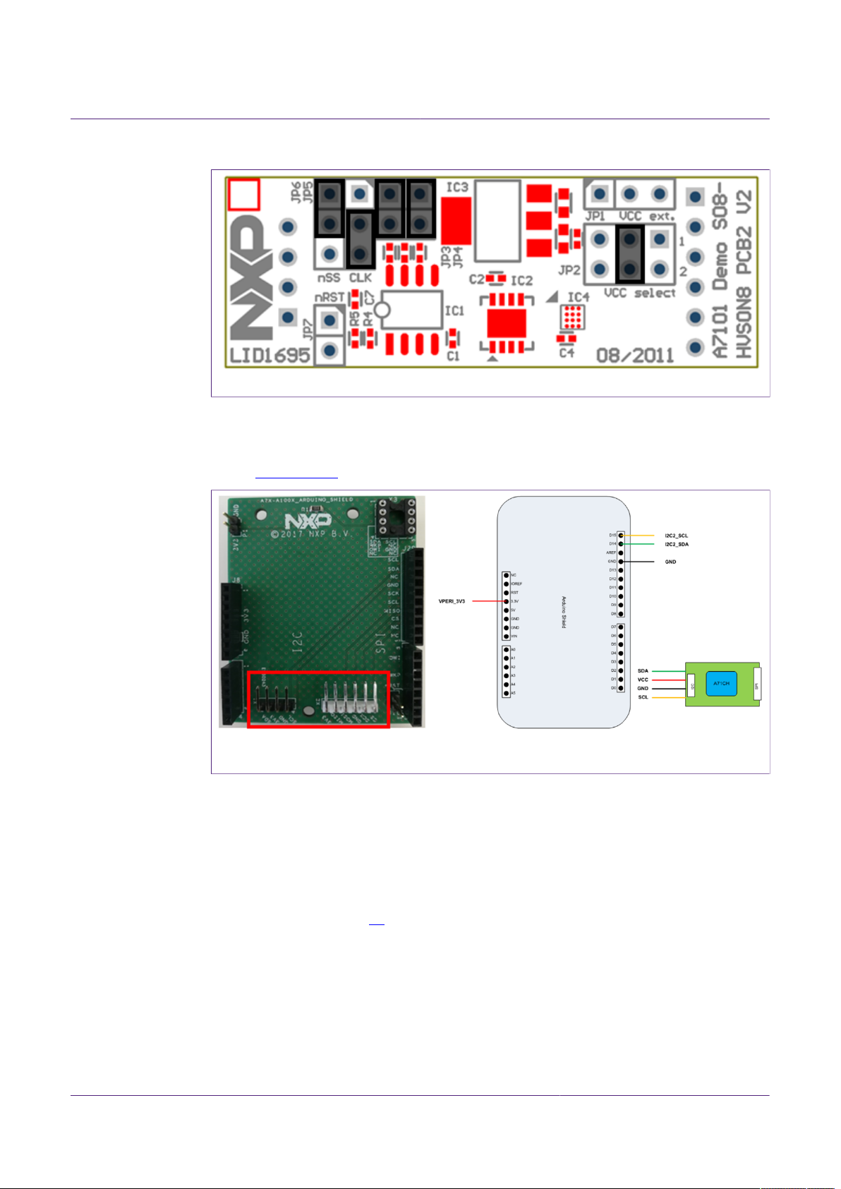
Figure 2 shows an image of the MiniPCB. It features two connectors that can be used
depending on the communication interface employed. The figure shows the jumpers
configuration that enables the use of the A71 I2C interface.
Figure 2. System architecture diagram
To enable the I2C communication protocol, it is necessary to configure JP5/6 according
to Table 2. JP2 connects the A71 to the on-board 3.3V voltage regulator on the MiniPCB
board. The jumpers JP3 and JP4 enable the I²C SDA/SCL pull-up resistors. JP7 can be
used to connect the A71 reset signal.
AN11803 All information provided in this document is subject to legal disclaimers. © NXP B.V. 2018. All rights reserved.
Application note Rev. 1.0 — 11 December 2018
COMPANY PUBLIC 353410 6 / 31
Page 7
NXP Semiconductors
Table 2. Default MiniPCB Jumper settings
Jumper Setting Usage
JP1 Not set External VCC connection
JP2 3-4 Connect A71 to 3.3V regulator on MiniPCB
JP3 Set Connect I²C SDA pull-up resistor
JP4 Set Connect I²C SCL pull-up resistor
JP6 1-2 Activate I²C interface
The board schematic and layout are shown in Figure 3 and Figure 4
AN11803
A71CL Quick start guide for A71CLARD-ALI and Kinetis
1-2 Use I²C address 0x92/0x93JP5
2-3 (Default) Use I²C address 0x90/0x91
Not set (Default) A71 operatesJP7
Set A71 IC reset
Figure 3. A71 Mini PCB board schematic
AN11803 All information provided in this document is subject to legal disclaimers. © NXP B.V. 2018. All rights reserved.
Application note Rev. 1.0 — 11 December 2018
COMPANY PUBLIC 353410 7 / 31
Page 8
NXP Semiconductors
Figure 4. Mini PCB board silkscreen with default jumper positions marked black
4.1.2 Arduino interface board
The Arduino header board permits the user to interface the A71 Mini PCB with the Kinetis
board. Section 4.1.2 shows the board pinout.
AN11803
A71CL Quick start guide for A71CLARD-ALI and Kinetis
Connection from the perspective of a matching Arduino Shield (top view)
Figure 5. A71 Arduino header
4.2 Freedom development platforms for Kinetis
The section details the Freedom development platforms for Kinetis supported by the
A71CL product support package.
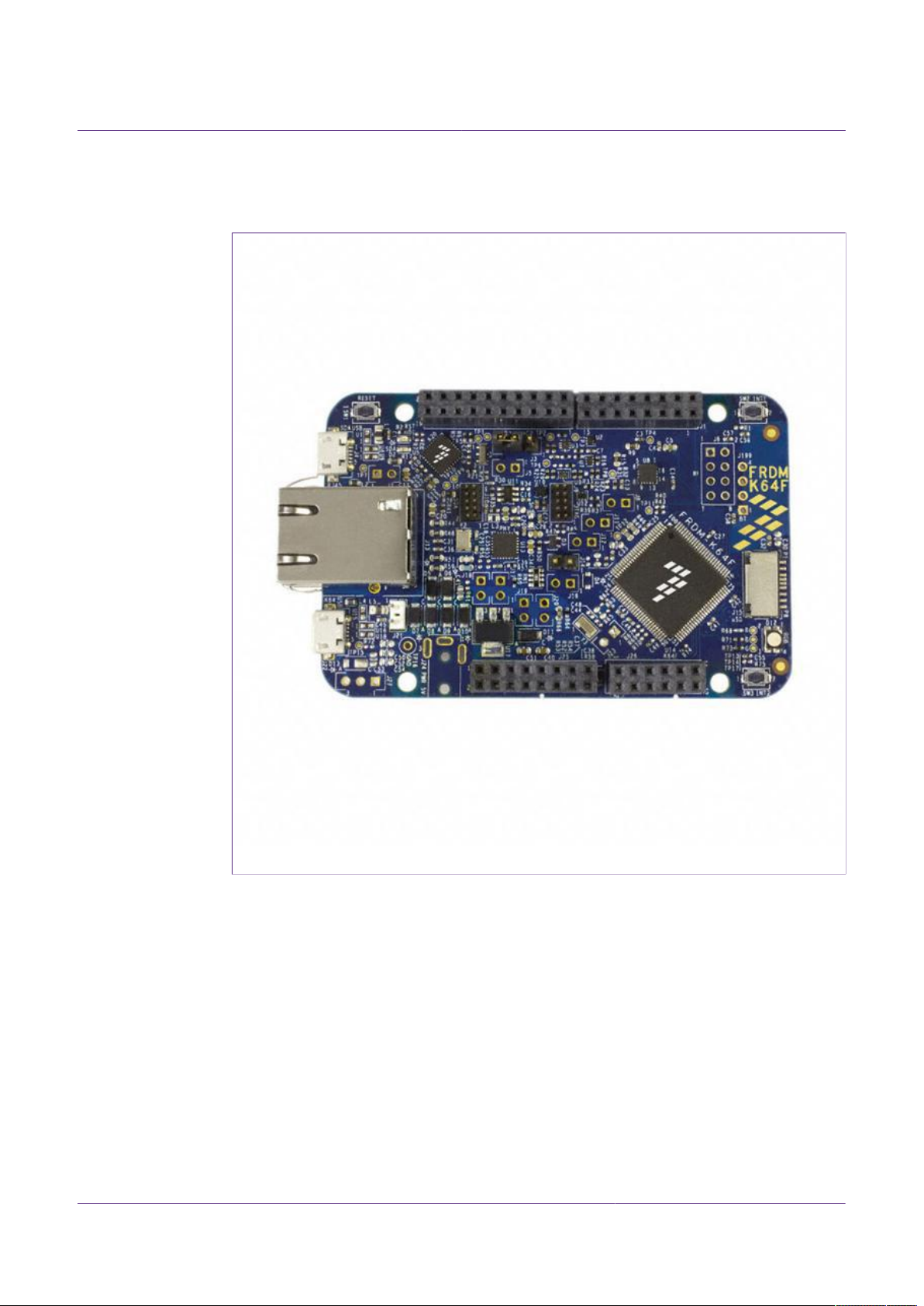
4.2.1 FRDM-K64F
The Kinetis FRDM-K64F [6] development platform is a simple, yet sophisticated design,
featuring a Kinetis K64 series microcontroller, built on the ARM® Cortex®-M4 core. The
FRDM-K64F can be used to evaluate the K64, K63, and K24 Kinetis K series devices. It
features the MK64FN1M0VLL12 MCU, which boasts the maximum operation frequency
of 120 MHz, 1 MB of flash, 256 KB RAM, a full-speed USB controller, Ethernet controller,
secure digital host controller, and analog and digital peripherals.
The FRDM-K64F hardware is form-factor compatible with the Arduino R3 pin layout,
providing a broad range of expansion board options. The onboard interface includes
a six-axis digital accelerometer & magnetometer, RGB LED, SDHC, add-on Bluetooth
AN11803 All information provided in this document is subject to legal disclaimers. © NXP B.V. 2018. All rights reserved.
Application note Rev. 1.0 — 11 December 2018
COMPANY PUBLIC 353410 8 / 31
Page 9
NXP Semiconductors
module, add-on RF module, Ethernet and OpenSDAv2, the NXP open-source hardware
embedded serial and debug adapter running an open-source bootloader.
AN11803
A71CL Quick start guide for A71CLARD-ALI and Kinetis
Figure 6. FRDM-K64F Freedom development platform for Kinetis K64, K63 and K24 MCUs
AN11803 All information provided in this document is subject to legal disclaimers. © NXP B.V. 2018. All rights reserved.
Application note Rev. 1.0 — 11 December 2018
COMPANY PUBLIC 353410 9 / 31
Page 10
NXP Semiconductors
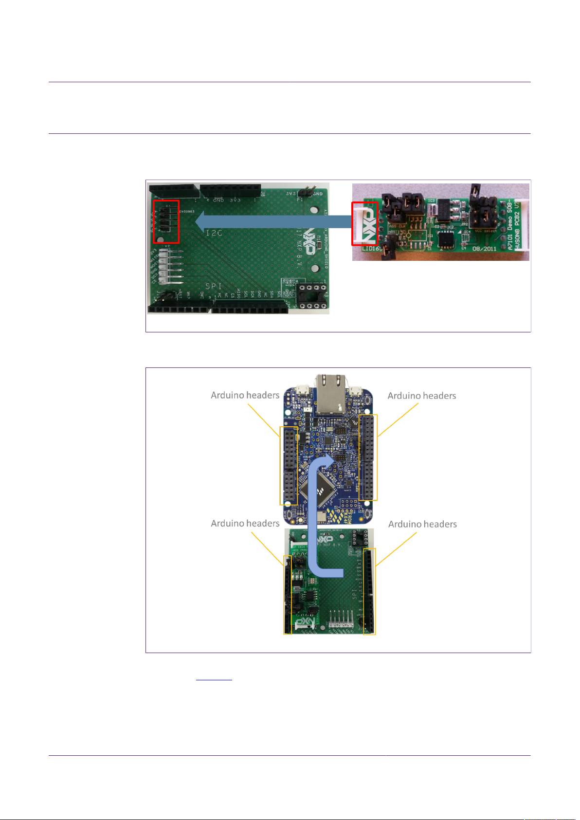
5 Hardware setup
The hardware setup consists of mounting the different boards together.
First, plug the A71 Mini PCB board to the I2C plug of the Arduino interface board.
Figure 7. A71 Arduino kit mounted on Kinetis FRDM-K64F board
Second, plug the A71CL into the Kinetis board using the Arduino adaptors. The Arduino
shield board comes with male connectors below and female connectors on top.
AN11803
A71CL Quick start guide for A71CLARD-ALI and Kinetis
Figure 8. Arduino interface board connected to the Kinetis board (FRDM-K64F)
Then, the A71 security IC is connected to the Kinetis board through the Arduino interface
board. See Figure 9
AN11803 All information provided in this document is subject to legal disclaimers. © NXP B.V. 2018. All rights reserved.
Application note Rev. 1.0 — 11 December 2018
COMPANY PUBLIC 353410 10 / 31
Page 11

NXP Semiconductors
AN11803
A71CL Quick start guide for A71CLARD-ALI and Kinetis
Figure 9. Arduino interface board connected to the Kinetis board (FRDM-K64F)
As can be observed, there are two USB connectors in the Kinetis boards FRDM-K64F.
See Figure 10. The USB connector highlighted in red corresponds to OpenSDA debug
port. This port will be used by the development PC to flash and debug the A71 examples
over an on-board debugger into the Kinetis MCU as well as to have a serial console.
The USB connector highlighted in yellow is directly connected to the K64F MCU and
functionality depends on the example programmed into the MCU.
Figure 10. Red USB indicates OpenSDA debug port. Yellow USB indicates K64F port
(FRDM-K64F)
AN11803 All information provided in this document is subject to legal disclaimers. © NXP B.V. 2018. All rights reserved.
Application note Rev. 1.0 — 11 December 2018
COMPANY PUBLIC 353410 11 / 31
Page 12

NXP Semiconductors
6 Software setup
This section details the required steps to complete the software setup for A71 security IC
and FRDM-K64F Freedom development platforms. The following items are needed:
• MCUxpresso IDE, see section 6.1. Here we use version 10.2.
• Kinetis SDK for MCUxpresso, see section 6.2. Here we use version 2.4.
• Hostlibrary code examples, see section 6.3.
• Serial terminal application, see section 6.5.
• OpenSDA debugger firmware update on Kinetis board, see section 6.6.
6.1 MCUXpresso IDE installation
MCUXpresso IDE is a fully featured software development environment for NXP’s ARMbased MCUs, and includes all the tools necessary to develop high-quality embedded
software applications in a timely and cost-effective fashion.
MCUXpresso IDE is based on the Eclipse IDE and includes the industry standard ARM
GNU toolchain. It brings developers an easy-to-use and unlimited code size development
environment for NXP MCUs based on Cortex-M cores (LPC, Kinetis and i.MX RT). The
IDE combines the best of the widely popular LPCXpresso and Kinetis Design Studio
IDEs, providing a common platform for all NXP Cortex-M microcontrollers.
AN11803
A71CL Quick start guide for A71CLARD-ALI and Kinetis
MCUXpresso IDE is a free toolchain providing developers with no restrictions on code
or debug sizes. It provides an intuitive and powerful interface with profiling, power
measurement on supported boards, GNU tool integration and library, multicore capable
debugger, trace functionality and more. MCUXpresso IDE debug connections support
Freedom, Tower, EVK, LPCXpresso and custom development boards with industry
leading open-source and commercial debug probes including LPC-Link2, P&E and
SEGGER.
The fully featured debugger supports both SWD and JTAG debugging, and features
direct download to on-chip and external flash memory.
The installation file of MCUXpresso can be found in [3]. The setup wizard will guide
the user through the process of installing MCUXpresso correctly. Since MCUXpresso
requires extra drivers during the installation, check all the items on the list to allow the
drivers to be installed. Make sure the checkbox for installing the NXP debug drivers is
activated. See Figure 11.
Note: Please, install MCUXpresso IDE version 10.2.0 or higher
AN11803 All information provided in this document is subject to legal disclaimers. © NXP B.V. 2018. All rights reserved.
Application note Rev. 1.0 — 11 December 2018
COMPANY PUBLIC 353410 12 / 31
Page 13

NXP Semiconductors
AN11803
A71CL Quick start guide for A71CLARD-ALI and Kinetis
Figure 11. MCUXpresso install wizard
6.2 Kinetis SDK package
To generate and download your customized SDK for your Kinetis FRDM board, you
can enter the MCUXpesso SDKBuilder website [5] with the button “Select Development
Board” and follow these steps:
1. Select your Kinetis FRDM board and click on ‘Build MCUXpresso SDK’; in this case
the selected board is the FRDM-K64F. See Figure 12.
Figure 12. Kinetis board selection
AN11803 All information provided in this document is subject to legal disclaimers. © NXP B.V. 2018. All rights reserved.
Application note Rev. 1.0 — 11 December 2018
COMPANY PUBLIC 353410 13 / 31
Page 14

NXP Semiconductors
1. In the next screen, select the software components, for this example no special items
Figure 13. Kinetis SDK configuration
AN11803
A71CL Quick start guide for A71CLARD-ALI and Kinetis
need to be selected and you can skip this step (see Figure 13) and directly click on
‘Download SDK’.
The downloaded SDK has to be imported in MCUXpresso IDE. To import the SDK into
MCUXpresso IDE, drag and drop the SDK file inside the red square (‘Installed SDKs’)
and then click ‘OK’ to confirm the operation. See Figure 14.
Figure 14. Installing the downloaded Kinetis SDK into MCUXpresso
6.3 Installing the A71CL example project
After downloading the A71CL host library [A71CL_HOST_SW] [1] follow these steps for
installation:
1. Double click on the downloaded A71CL executable A71CL hostlibrary file.
2. Click ‘Yes’ If pop up comes saying “Do you want to allow this app from an unknown
publisher to make changes to your device ?”.
3. Read License agreement and accept the license agreement by checking(✔) “I accept
the terms of the License Agreement”, then click next.
AN11803 All information provided in this document is subject to legal disclaimers. © NXP B.V. 2018. All rights reserved.
Application note Rev. 1.0 — 11 December 2018
COMPANY PUBLIC 353410 14 / 31
Page 15

NXP Semiconductors
AN11803
A71CL Quick start guide for A71CLARD-ALI and Kinetis
Figure 15. A71CL Hostlibrary License
1. Choose destination folder and click next.
Figure 16. Select install folder
1. Choose start menu folder and click Install.
AN11803 All information provided in this document is subject to legal disclaimers. © NXP B.V. 2018. All rights reserved.
Application note Rev. 1.0 — 11 December 2018
COMPANY PUBLIC 353410 15 / 31
Page 16

NXP Semiconductors
AN11803
A71CL Quick start guide for A71CLARD-ALI and Kinetis
Figure 17. Select start menu entry
1. Click Close After Installation Complete.
Figure 18. Installation finished
6.4 Importing the example projects in MCUXpresso IDE
There are generally two possible ways to import the A71 project examples in
MCUXpresso IDE, depending if we are using the MCUXpresso project files bundled with
the A71CL Host Software package or if the installed SDK package already contains the
A71CL middleware:
AN11803 All information provided in this document is subject to legal disclaimers. © NXP B.V. 2018. All rights reserved.
Application note Rev. 1.0 — 11 December 2018
COMPANY PUBLIC 353410 16 / 31
Page 17

NXP Semiconductors
• Importing the A71CL-ALI example projects from the installed Kinetis-SDK. This SDK is
not available yet and as such this way is not supported yet.
• Importing the A71CL example projects from local drive (included in the A71CL-ALI Host
Library).
6.4.1 Importing A71CL example projects from local drive
Here the project files bundled with the A71CL Host Software package can be used.
The A71CL Host Software Package can be downloaded from [A71CL_HOST_SW
A71CH_HOST_SW] [1].
After unpacking the package the example project files are in the subfolder
‘mcux_projects_frdmk64f’ in the case of the FRDM K64F board. It contains one example
project:
• frdmk64f_id2_client_sdk: demonstrate the connection of the id2_client_sdk as available
on Github [ https://github.com/alibaba/id2_client_sdk ] to the A71CL and run the
testsuite
To import a project from file system, click on ‘Import project(s) from file system…’ in the
‘Quick start Panel’ located in the bottom left. See Figure 19.
AN11803
A71CL Quick start guide for A71CLARD-ALI and Kinetis
Figure 19. Import project from file system
After clicking the import option, a new pop-up will open. In the ‘Project directory
(unpacked)’ field, browse and point to the correct project directory, see Figure 20. Then,
click on ‘Next’.
AN11803 All information provided in this document is subject to legal disclaimers. © NXP B.V. 2018. All rights reserved.
Application note Rev. 1.0 — 11 December 2018
COMPANY PUBLIC 353410 17 / 31
Page 18

NXP Semiconductors
Figure 20. Project directory to import
AN11803
A71CL Quick start guide for A71CLARD-ALI and Kinetis
Finally, select all the available example projects, deselect “Copy projects into the
workspace” and then click on ‘Finish’. In case you want to have the same project
imported multiple times independently you need to unpack it into distinct directories and
import these individually as the code needs to get referenced instead of copied.
Figure 21. Project directory to import
6.5 Terminal setup
A terminal application must be executed from the development PC to interact with the
Kinetis board. Any terminal supporting a serial port interface can be used.
In this document, Tera Term is used and can be downloaded from [2]. The setup wizard
will guide the user through the installation. The standard installation can be chosen for
this purpose. Once it is finished, Tera Term can be started.
AN11803 All information provided in this document is subject to legal disclaimers. © NXP B.V. 2018. All rights reserved.
Application note Rev. 1.0 — 11 December 2018
COMPANY PUBLIC 353410 18 / 31
Page 19

NXP Semiconductors
6.6 OpenSDA configuration
OpenSDA is a serial and debug adapter built into the Kinetis board. It provides a bridge
between the development PC and the Kinetis MCU, which can be used for debugging,
flash programming and serial communication all over USB.
Note: This section explains how to install the correct OpenSDA bootloader firmware
version to the Kinetis FRDM-K64F board. This needs to be done for debugging, flash
programming, and serial communication over a single USB connection between a host
and an embedded target processor. If this section is not followed carefully, it is possible
the examples will not be executed.
To configure OpenSDA into the Kinetis FRDM board, an OpenSDA bootloader (.bin
file) should be downloaded from OpenSDA website [4]. Scroll down the page to section
‘Compatible Evaluation Boards’ and search for the target Kinetis FRDM board. In this
case, Figure 22 depicts the OpenSDA bootloader version defined for the Kinetis FRDM
K64F: version 2.0.
AN11803
A71CL Quick start guide for A71CLARD-ALI and Kinetis
Figure 22. OpenSDA bootloader version for the Kinetis FRDM-K64F
Once the OpenSDA bootloader version is identified, click in the ‘Downloads’, scroll down
until ‘J-Link OpenSDA – Generic Firmwares’ appears and download the desired version.
Figure 23 illustrates the process; in this case OpenSDA V2 Bootloader has been
selected, according to the compatible evaluation boards table previously mentioned.
Figure 23. Desired firmware for the Kinetis FRDM-K64F
AN11803 All information provided in this document is subject to legal disclaimers. © NXP B.V. 2018. All rights reserved.
Application note Rev. 1.0 — 11 December 2018
COMPANY PUBLIC 353410 19 / 31
Page 20

NXP Semiconductors
To write the downloaded firmware into the Kinetis FRDM board, the bootloader mode
should be enabled. For this, press ‘Reset’ button and, while holding down the button,
connect a USB cable to the debugger port of the Kinetis board (e.g., FRDM K64,
Figure 24).
AN11803
A71CL Quick start guide for A71CLARD-ALI and Kinetis
Figure 24. Enabling bootloader mode
After connecting the USB cable to the Kinetis board, the green led located inside the
yellow square will start blinking and the development PC will show a new drive called
‘BOOTLOADER’. The drive may disappear again after ~30 seconds in case there is no
interaction, in this case disconnect and connect again with pressing the ‘Reset’ button.
Drag the downloaded firmware directly into the drive, see Figure 25. Once the file is
copied inside the ‘BOOTLOADER’ drive the LED will soon start blink fast, then unplug the
Kinetis board and plug it again. The green led stays on, thus indicating that the OpenSDA
bootloader firmware has been configured correctly.
Figure 25. Copying the firmware into the Kinetis board in ‘BOOTLOADER’ mode
AN11803 All information provided in this document is subject to legal disclaimers. © NXP B.V. 2018. All rights reserved.
Application note Rev. 1.0 — 11 December 2018
COMPANY PUBLIC 353410 20 / 31
Page 21

NXP Semiconductors
A71CL Quick start guide for A71CLARD-ALI and Kinetis
7 A71 application examples execution
The A71 Host software package [A71CL_HOST_SW] [1] includes one application
examples:
• id2 client sdk: A sample project executing the ID2 testsuite against the A71 secure
element
7.1 Running the example
The A71 security IC is connected to the Kinetis board through the Arduino interface
board. With MCUXpresso IDE (installed in the Windows PC) the Kinetis MCU is
programmed, so that it executes the example application.
The execution output can be seen either in the MCUXpresso IDE console or by using
Tera Term. Both cases are explained step by step in this section.
7.1.1 Printing the output with MCUXpresso IDE
Assuming that the SDK has already been installed, and the project examples have been
imported as explained in section 6.3, open MCUXpresso IDE and take the following steps
(Figure 26):
AN11803
1. Select the project “frdmk64f_id2_client_sdk” in the “Project Explorer”
2. Click on ‘Debug’ in the Quickstart Panel.
3. Select J-Link OpenSDA probe and click on ‘OK’. Make sure the OpenSDA serial port
is connected to the Windows platform (Figure 10, highlighted in red)
4. If a ‘Terms of use’ pop-up appears, check ‘Do not show this message again for today’
box and click ‘Accept’.
Figure 26. Configuration steps to debug using MCUXpresso IDE Console
AN11803 All information provided in this document is subject to legal disclaimers. © NXP B.V. 2018. All rights reserved.
Application note Rev. 1.0 — 11 December 2018
COMPANY PUBLIC 353410 21 / 31
Page 22

NXP Semiconductors
After that, the project will start to compile and execute automatically. Once the process
is finished, the user should press the ‘F8’ key to run the program. Figure 27 shows the
output in the console tab.
Figure 27. Example of generated output printed in MCUXpresso IDE Console
7.1.2 Printing the output on UART console using Tera Term
The output of the A71CL example execution can be switched to be seen by using Tera
Term. For this, the SDK Debug Console should be configured to be in ‘UART Console’
mode. Figure 28 illustrates the process; simply click on ‘Quick Settings’, ‘SDK Debug
Console’ and finally choose ‘UART Console’.
AN11803
A71CL Quick start guide for A71CLARD-ALI and Kinetis
Figure 28. SDK Debug Console in UART Console mode
This ‘Quick Setting’ takes automatic care to set the pre-processor define
‘SDK_DEBUGCONSOLE’ to 1 to activate the UART console (0 for the semi hosting
console)
Note:
If the option UART console or Semihost console cannot be clicked, make sure that there
is not a running session and that the project is selected in the project explorer. If there is
a running session (a running thread inside ‘Debug’ window), click on the 'Terminate all
debug sessions’ button.
Finally, to run the example project:
1. First, click on ‘Build’.
2. Then, click on ‘Debug’ to run the project in the Kinetis board.
AN11803 All information provided in this document is subject to legal disclaimers. © NXP B.V. 2018. All rights reserved.
Application note Rev. 1.0 — 11 December 2018
COMPANY PUBLIC 353410 22 / 31
Page 23

NXP Semiconductors
AN11803
A71CL Quick start guide for A71CLARD-ALI and Kinetis
Figure 29. Build and Debug options
On Tera Term, the first thing that should be configured is a new connection, see
Figure 30. The user should choose a Serial connection and a port. This port can be
checked in the Window’s device manager under “Ports (COM & LPT)” menu.
Figure 30. Tera Term new connection
Then, the selected port should be set as shown in Figure 31.
AN11803 All information provided in this document is subject to legal disclaimers. © NXP B.V. 2018. All rights reserved.
Application note Rev. 1.0 — 11 December 2018
COMPANY PUBLIC 353410 23 / 31
Page 24

NXP Semiconductors
AN11803
A71CL Quick start guide for A71CLARD-ALI and Kinetis
Figure 31. Serial port setup
The terminal window should be configured as shown in Figure 32.
Figure 32. Terminal setup
When the MCU now executes the example the log output will be shown in Tera Term.
See Figure 33.
AN11803 All information provided in this document is subject to legal disclaimers. © NXP B.V. 2018. All rights reserved.
Application note Rev. 1.0 — 11 December 2018
COMPANY PUBLIC 353410 24 / 31
Page 25

NXP Semiconductors
Figure 33. Generated output printed in Tera Term
AN11803
A71CL Quick start guide for A71CLARD-ALI and Kinetis
7.2 Sample Execution Log
As the secure element is individually pre-provisoned with an Alibaba key which the
testsuite does not know it can not run all test steps. The last step which tries decrypting
the SE response will fail as the testsuite assumes only a default key.
AN11803 All information provided in this document is subject to legal disclaimers. © NXP B.V. 2018. All rights reserved.
Application note Rev. 1.0 — 11 December 2018
COMPANY PUBLIC 353410 25 / 31
Page 26

NXP Semiconductors
AN11803
A71CL Quick start guide for A71CLARD-ALI and Kinetis
Figure 34. Begin and end of ID2 testsuite execution log
The id2_client_decrypt error on the end of the testsuite is expected, as the testsuite
cannot know the secret key inside the secure element.
AN11803 All information provided in this document is subject to legal disclaimers. © NXP B.V. 2018. All rights reserved.
Application note Rev. 1.0 — 11 December 2018
COMPANY PUBLIC 353410 26 / 31
Page 27

NXP Semiconductors
8 References
[1] [A71CL_HOST_SW] A71CL Alibaba Host Software Package (zip file) In Software
[2] [TERA_TERM] Tera Term terminal - https://osdn.net/projects/ttssh2/releases/
[3] [MCUXPRESSO_IDE] MCUXpresso IDE - https://www.nxp.com/support/developer-
[4] [OPENSDA_FIRMWARE] OpenSDA / OpenSDA V2 website - https://
[5] [SDKBUILDER] MCUXPresso SBKBuilder website - https://mcuxpresso.nxp.com/
[6] [FRDM_K64F] Kinetis FRDM-K64F - https://www.nxp.com/products/processors-
AN11803
A71CL Quick start guide for A71CLARD-ALI and Kinetis
tab of http://www.nxp.com/A71CL
resources/software-development-tools/mcuxpresso-software-and-tools/mcuxpressointegrated-development-environment-ide:MCUXpresso-IDE
www.segger.com/products/debug-probes/j-link/models/other-j-links/opensda-sda-v2/
en/select
and-microcontrollers/arm-based-processors-and-mcus/kinetis-cortex-m-mcus/kseriesperformancem4/k2x-usb/freedom-development-platform-for-kinetis-k64-k63and-k24-mcus:FRDM-K64F
AN11803 All information provided in this document is subject to legal disclaimers. © NXP B.V. 2018. All rights reserved.
Application note Rev. 1.0 — 11 December 2018
COMPANY PUBLIC 353410 27 / 31
Page 28

NXP Semiconductors
9 Legal information
9.1 Definitions
Draft — The document is a draft version only. The content is still under
internal review and subject to formal approval, which may result in
modifications or additions. NXP Semiconductors does not give any
representations or warranties as to the accuracy or completeness of
information included herein and shall have no liability for the consequences
of use of such information.
9.2 Disclaimers
Limited warranty and liability — Information in this document is believed
to be accurate and reliable. However, NXP Semiconductors does not
give any representations or warranties, expressed or implied, as to the
accuracy or completeness of such information and shall have no liability
for the consequences of use of such information. NXP Semiconductors
takes no responsibility for the content in this document if provided by an
information source outside of NXP Semiconductors. In no event shall NXP
Semiconductors be liable for any indirect, incidental, punitive, special or
consequential damages (including - without limitation - lost profits, lost
savings, business interruption, costs related to the removal or replacement
of any products or rework charges) whether or not such damages are based
on tort (including negligence), warranty, breach of contract or any other
legal theory. Notwithstanding any damages that customer might incur for
any reason whatsoever, NXP Semiconductors’ aggregate and cumulative
liability towards customer for the products described herein shall be limited
in accordance with the Terms and conditions of commercial sale of NXP
Semiconductors.
Right to make changes — NXP Semiconductors reserves the right to
make changes to information published in this document, including without
limitation specifications and product descriptions, at any time and without
notice. This document supersedes and replaces all information supplied prior
to the publication hereof.
AN11803
A71CL Quick start guide for A71CLARD-ALI and Kinetis
customer’s third party customer(s). NXP does not accept any liability in this
respect.
Export control — This document as well as the item(s) described herein
may be subject to export control regulations. Export might require a prior
authorization from competent authorities.
Evaluation products — This product is provided on an “as is” and “with all
faults” basis for evaluation purposes only. NXP Semiconductors, its affiliates
and their suppliers expressly disclaim all warranties, whether express,
implied or statutory, including but not limited to the implied warranties of
non-infringement, merchantability and fitness for a particular purpose. The
entire risk as to the quality, or arising out of the use or performance, of this
product remains with customer. In no event shall NXP Semiconductors, its
affiliates or their suppliers be liable to customer for any special, indirect,
consequential, punitive or incidental damages (including without limitation
damages for loss of business, business interruption, loss of use, loss of
data or information, and the like) arising out the use of or inability to use
the product, whether or not based on tort (including negligence), strict
liability, breach of contract, breach of warranty or any other theory, even if
advised of the possibility of such damages. Notwithstanding any damages
that customer might incur for any reason whatsoever (including without
limitation, all damages referenced above and all direct or general damages),
the entire liability of NXP Semiconductors, its affiliates and their suppliers
and customer’s exclusive remedy for all of the foregoing shall be limited to
actual damages incurred by customer based on reasonable reliance up to
the greater of the amount actually paid by customer for the product or five
dollars (US$5.00). The foregoing limitations, exclusions and disclaimers
shall apply to the maximum extent permitted by applicable law, even if any
remedy fails of its essential purpose.
Translations — A non-English (translated) version of a document is for
reference only. The English version shall prevail in case of any discrepancy
between the translated and English versions.
9.3 Licenses
Suitability for use — NXP Semiconductors products are not designed,
authorized or warranted to be suitable for use in life support, life-critical or
safety-critical systems or equipment, nor in applications where failure or
malfunction of an NXP Semiconductors product can reasonably be expected
to result in personal injury, death or severe property or environmental
damage. NXP Semiconductors and its suppliers accept no liability for
inclusion and/or use of NXP Semiconductors products in such equipment or
applications and therefore such inclusion and/or use is at the customer’s own
risk.
Applications — Applications that are described herein for any of these
products are for illustrative purposes only. NXP Semiconductors makes
no representation or warranty that such applications will be suitable
for the specified use without further testing or modification. Customers
are responsible for the design and operation of their applications and
products using NXP Semiconductors products, and NXP Semiconductors
accepts no liability for any assistance with applications or customer product
design. It is customer’s sole responsibility to determine whether the NXP
Semiconductors product is suitable and fit for the customer’s applications
and products planned, as well as for the planned application and use of
customer’s third party customer(s). Customers should provide appropriate
design and operating safeguards to minimize the risks associated with
their applications and products. NXP Semiconductors does not accept any
liability related to any default, damage, costs or problem which is based
on any weakness or default in the customer’s applications or products, or
the application or use by customer’s third party customer(s). Customer is
responsible for doing all necessary testing for the customer’s applications
and products using NXP Semiconductors products in order to avoid a
default of the applications and the products or of the application or use by
ICs with DPA Countermeasures functionality
NXP ICs containing functionality
implementing countermeasures to
Differential Power Analysis and Simple
Power Analysis are produced and sold
under applicable license from Cryptography
Research, Inc.
9.4 Trademarks
Notice: All referenced brands, product names, service names and
trademarks are the property of their respective owners.
Kinetis — is a trademark of NXP B.V.
AMBA, Arm, Arm7, Arm7TDMI, Arm9, Arm11, Artisan, big.LITTLE,
Cordio, CoreLink, CoreSight, Cortex, DesignStart, DynamIQ, Jazelle,
Keil, Mali, Mbed, Mbed Enabled, NEON, POP, RealView, SecurCore,
Socrates, Thumb, TrustZone, ULINK, ULINK2, ULINK-ME, ULINK-PLUS,
ULINKpro, µVision, Versatile — are trademarks or registered trademarks
of Arm Limited (or its subsidiaries) in the US and/or elsewhere. The related
technology may be protected by any or all of patents, copyrights, designs
and trade secrets. All rights reserved.
Bluetooth — The Bluetooth word mark and logos are registered trademarks
owned by Bluetooth SIG, Inc. and any use of such marks by NXP
Semiconductors is under license.
AN11803 All information provided in this document is subject to legal disclaimers. © NXP B.V. 2018. All rights reserved.
Application note Rev. 1.0 — 11 December 2018
COMPANY PUBLIC 353410 28 / 31
Page 29

NXP Semiconductors
A71CL Quick start guide for A71CLARD-ALI and Kinetis
AN11803
Tables
Tab. 1. Needed Boards ................................................. 6 Tab. 2. Default MiniPCB Jumper settings ......................7
AN11803 All information provided in this document is subject to legal disclaimers. © NXP B.V. 2018. All rights reserved.
Application note Rev. 1.0 — 11 December 2018
COMPANY PUBLIC 353410 29 / 31
Page 30

NXP Semiconductors
Figures
AN11803
A71CL Quick start guide for A71CLARD-ALI and Kinetis
Fig. 1. System architecture diagram .............................5
Fig. 2. System architecture diagram .............................6
Fig. 3. A71 Mini PCB board schematic ........................ 7
Fig. 4. Mini PCB board silkscreen with default
jumper positions marked black ..........................8
Fig. 5. A71 Arduino header .......................................... 8
Fig. 6. FRDM-K64F Freedom development
platform for Kinetis K64, K63 and K24 MCUs ....9
Fig. 7. A71 Arduino kit mounted on Kinetis FRDM-
K64F board ..................................................... 10
Fig. 8. Arduino interface board connected to the
Kinetis board (FRDM-K64F) ............................10
Fig. 9. Arduino interface board connected to the
Kinetis board (FRDM-K64F) ............................11
Fig. 10. Red USB indicates OpenSDA debug port.
Yellow USB indicates K64F port (FRDM-
K64F) ...............................................................11
Fig. 11. MCUXpresso install wizard ............................. 13
Fig. 12. Kinetis board selection .................................... 13
Fig. 13. Kinetis SDK configuration ............................... 14
Fig. 14. Installing the downloaded Kinetis SDK into
MCUXpresso ................................................... 14
Fig. 15. A71CL Hostlibrary License ..............................15
Fig. 16. Select install folder .......................................... 15
Fig. 17. Select start menu entry ................................... 16
Fig. 18. Installation finished .......................................... 16
Fig. 19. Import project from file system ........................ 17
Fig. 20. Project directory to import ............................... 18
Fig. 21. Project directory to import ............................... 18
Fig. 22. OpenSDA bootloader version for the Kinetis
FRDM-K64F .................................................... 19
Fig. 23. Desired firmware for the Kinetis FRDM-
K64F ................................................................ 19
Fig. 24. Enabling bootloader mode .............................. 20
Fig. 25. Copying the firmware into the Kinetis board
in ‘BOOTLOADER’ mode ................................20
Fig. 26. Configuration steps to debug using
MCUXpresso IDE Console ..............................21
Fig. 27. Example of generated output printed in
MCUXpresso IDE Console ..............................22
Fig. 28. SDK Debug Console in UART Console
mode ............................................................... 22
Fig. 29. Build and Debug options ................................. 23
Fig. 30. Tera Term new connection ............................. 23
Fig. 31. Serial port setup .............................................. 24
Fig. 32. Terminal setup ................................................ 24
Fig. 33. Generated output printed in Tera Term ...........25
Fig. 34. Begin and end of ID2 testsuite execution log ... 26
AN11803 All information provided in this document is subject to legal disclaimers. © NXP B.V. 2018. All rights reserved.
Application note Rev. 1.0 — 11 December 2018
COMPANY PUBLIC 353410 30 / 31
Page 31

NXP Semiconductors
Contents
1 Introduction ......................................................... 3
2 A71CL Overview ..................................................4
3 System description ............................................. 5
4 Hardware overview ............................................. 6
4.1 A71CL Arduino compatible development kit
(A71CLARD) ...................................................... 6
4.1.1 A71 Mini PCB board ..........................................6
4.1.2 Arduino interface board ..................................... 8
4.2 Freedom development platforms for Kinetis ...... 8
4.2.1 FRDM-K64F .......................................................8
5 Hardware setup ................................................. 10
6 Software setup .................................................. 12
6.1 MCUXpresso IDE installation .......................... 12
6.2 Kinetis SDK package .......................................13
6.3 Installing the A71CL example project .............. 14
6.4 Importing the example projects in
MCUXpresso IDE ............................................ 16
6.4.1 Importing A71CL example projects from
local drive ........................................................ 17
6.5 Terminal setup ................................................. 18
6.6 OpenSDA configuration ................................... 19
7 A71 application examples execution ...............21
7.1 Running the example .......................................21
7.1.1 Printing the output with MCUXpresso IDE ....... 21
7.1.2 Printing the output on UART console using
Tera Term ........................................................22
7.2 Sample Execution Log .....................................25
8 References ......................................................... 27
9 Legal information .............................................. 28
AN11803
A71CL Quick start guide for A71CLARD-ALI and Kinetis
Please be aware that important notices concerning this document and the product(s)
described herein, have been included in section 'Legal information'.
© NXP B.V. 2018. All rights reserved.
For more information, please visit: http://www.nxp.com
For sales office addresses, please send an email to: salesaddresses@nxp.com
Date of release: 11 December 2018
Document identifier: AN11803
Document number: 353410
 Loading...