

Page 1

UM11449
88MW32x Labtool User Guide
Rev. 2.0 — 4 August 2020 User manual
Document information
Information Content
Keywords Labtool setup, DUT setup, Labtool usage, Wi-Fi Labtool commands
Abstract Provides the instructions to set up the testing environment, and the
commands to test Wi-Fi RF.
Page 2

NXP Semiconductors
88MW32x Labtool User Guide
UM11449
Revision history
Document revision history
Revision Date Description
2.0 4-Aug-2020 Applied NXP branding, format and numbering scheme. No changes in the content.
1.0 11-Mar-2019 Initial release
UM11449 All information provided in this document is subject to legal disclaimers. © NXP B.V. 2020. All rights reserved.
User manual Rev. 2.0 — 4 August 2020
2 / 21
Page 3

NXP Semiconductors
1 Introduction
This document provides an overview of Labtool for 88MW320 and 88MW322 devices.
Labtool is a software test tool used to control and run various RF and regulatory
compliance tests.
1.1 Related documents
Table 1. Related documents
Document type Descriptive title
Datasheet 88MW320-88MW322 Wireless Microcontroller - IEEE 802.11n/g/b
Reference design
documents
Reference design
documents
UM11449
88MW32x Labtool User Guide
RD-88MW320-QFN-1B-2A v1.0 reference design documents Schematics, ASCII files, Gerber files, Pad layout, and bill of material
RD-88MW322-QFN-1B-2A v1.0 reference design documents Schematics, ASCII files, Gerber files, Pad layout, and bill of material
UM11449 All information provided in this document is subject to legal disclaimers. © NXP B.V. 2020. All rights reserved.
User manual Rev. 2.0 — 4 August 2020
3 / 21
Page 4
NXP Semiconductors
2 Overview
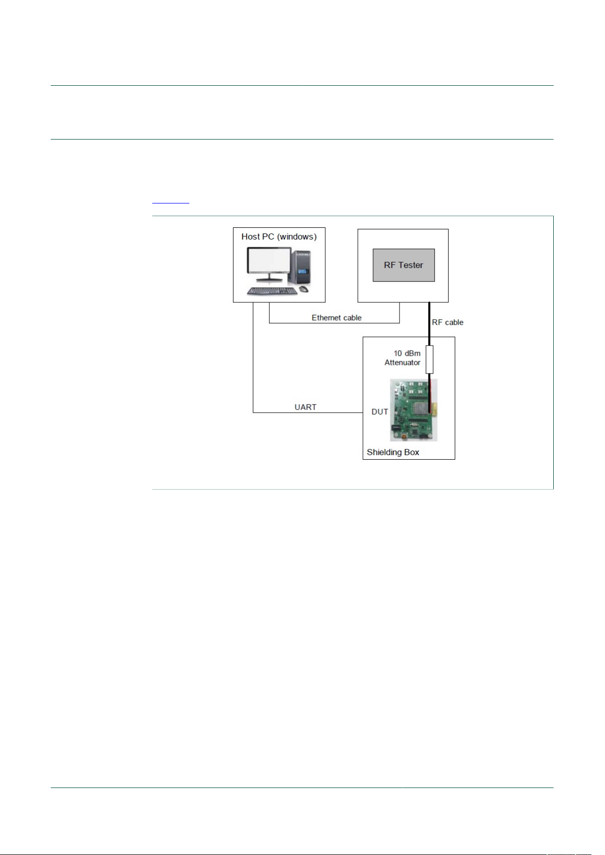
The Labtool application runs on a Windows PC. The Device Under Test (DUT) needs to
run the bridge application and MFG firmware. The PC is connected to the DUT via the
USB Virtual UART interface.
Figure 1 shows the Labtool test setup structure.
UM11449
88MW32x Labtool User Guide
Figure 1. Labtool test setup
Ensure to calibrate the RF cable losses on the Manufacturing (MFG) test setup across
different frequencies. This can be accomplished by using a network analyzer to measure
the entire path loss (S21).
For example, the entire path loss between the RF tester and the 88MW32x reference
design is measured from the N-Type to SMA adapter and DC block that connects to the
RF tester all the way to the W.FL cable/probe end that connects to the W.FL connector
on the 88MW32x reference designs.
UM11449 All information provided in this document is subject to legal disclaimers. © NXP B.V. 2020. All rights reserved.
User manual Rev. 2.0 — 4 August 2020
4 / 21
Page 5

NXP Semiconductors
3 Wi-Fi MFG firmware and bridge setup
This section describes the procedure on how to setup the Wi-Fi MFG firmware and
launch the bridge on a host PC to start the test.
The bridge firmware and Wi-Fi MFG firmware are located in the 88MW32x Flash. The
host Labtool communicates with the DUT firmware thru the virtualized UART interface.
See Figure 2.
Figure 2. Labtool, bridge, and Wi-Fi MFG firmware
UM11449
88MW32x Labtool User Guide
Program the bridge firmware and WLAN MFG firmware into the Flash through the
88MW32x reference design. The bridge firmware can be built thru the Software
Development Kit (SDK) environment. The Labtool release package includes the WLAN
MFG firmware.
Perform the following tasks:
1. Follow the document “Development-Host-Setup.pdf” in the SDK document package to
set up the environment to compile.
2. Follow the document “DeveloperReference-BuildSystem.pdf” to make the bridge
firmware.
3. Follow the document “Developing with WMSDK.pdf” and use the tool “flashprog.py”
in the SDK package to program the bridge firmware and WLAN MFG firmware into
Flash.
When setting up the environment to compile and preparing to build the bridge firmware,
configure as follows:
1. Execute the following command:
>make config
2. In the menu, choose the following options:
Platform type >
Wi-Fi Chipset >
Configures UART rcv Buffers of size 1024 (UART_LARGE_RCV_BUF) {N/Y]:Y
1.88MC200-based Platforms (CPU_MC200)
2.88MW300-based Platforms (CPU_MW300)
Choice {2-1]: 2
1.878x-based Chipset (WiFi-878x)
2.8801-based Chipset (WiFi-8801)
Choice {2-1]: 2
3. Keep the other parameters as the default configuration.
UM11449 All information provided in this document is subject to legal disclaimers. © NXP B.V. 2020. All rights reserved.
User manual Rev. 2.0 — 4 August 2020
5 / 21
Page 6
NXP Semiconductors
4 Labtool setup
4.1 Environment setup
The host PC runs on a 64-bit Windows operating system. The procedure to set up the
environment is as follows.
Step 1 - Download and extract 88MW32x MFG firmware
Download the latest 88MW32x MFG firmware release from NXP website. The last MFG
release version of the 88MW30x is reused for 88MW32x SoC.
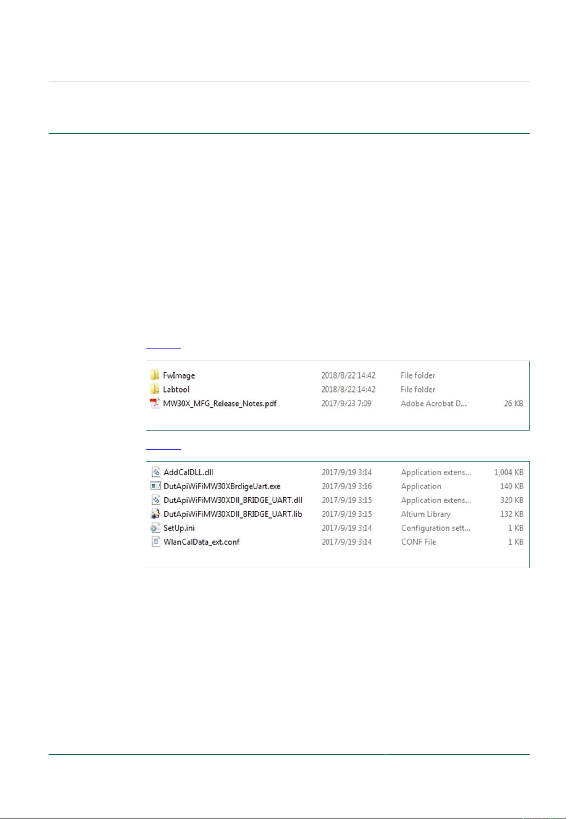
Unzip the MFG firmware release package into any directory. Inside the release package,
there are a few folders.
• FwImage folder contains the MFG firmware for the 88MW32x device
• Labtool folder contains the tool used to control the 88MW32x device for the MFG tests
and physical layer tests
Figure 3 shows the files in the MFG firmware release package.
UM11449
88MW32x Labtool User Guide
Figure 3. Files in MFG firmware release package
Figure 4 shows the Labtool folder content.
Figure 4. Labtool folder content
The Labtool folder includes:
• DutApiWiFiMW30xBridgeUart.exe: Labtool executable
• SetUp.ini: Configuration file for Labtool executable
UM11449 All information provided in this document is subject to legal disclaimers. © NXP B.V. 2020. All rights reserved.
User manual Rev. 2.0 — 4 August 2020
6 / 21
Page 7
NXP Semiconductors
4.1.1 Step 2 - Edit Setup.ini file
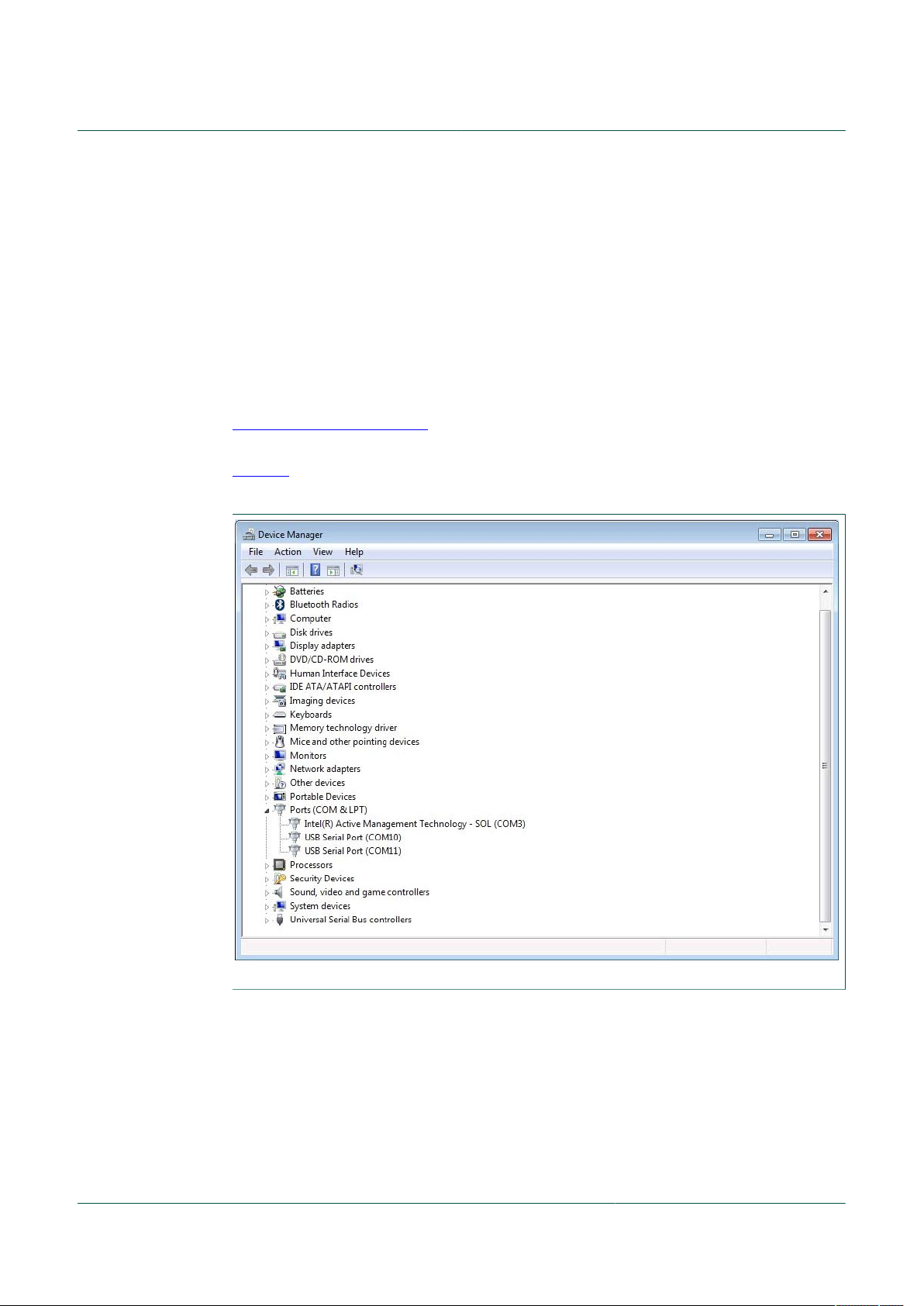
Open the “SetUp.ini” file using a text editor. Edit the ComNo parameter to match the USB
serial port number of the host. For the reference design boards, it will be virtualized as
two UART ports. Use a big port number.
[COMSET]
ComNo = 11
BaudRate = 1500000
Install the Zadig USB driver using the following link on the Windows PC for the reference
design board:
http://zadig.akeo.ie/
Once installed, the USB serial port number can be found in the Device Manager (see
Figure 5). Choose either the DB9 connector or Future Technologies Device International
(FTDI) based on the USB serial connector to connect to the Windows PC.
UM11449
88MW32x Labtool User Guide
Figure 5. Virtual UART ports in Device Manager
UM11449 All information provided in this document is subject to legal disclaimers. © NXP B.V. 2020. All rights reserved.
User manual Rev. 2.0 — 4 August 2020
7 / 21
Page 8

NXP Semiconductors
4.2 Starting Labtool
Ensure the bridge application is running prior to starting the Labtool application. The
procedure to start the Labtool application is as follows:
1. Double-click on DutApiWiFiMW30xBridgeUart.exe file.
UM11449
88MW32x Labtool User Guide
Figure 6 shows the Labtool start window for 88MW32x device.
Figure 6. Labtool start window
2. At the command prompt, enter 1 to start WLAN radio operation.
3. To confirm whether the bridge and host setups are working properly, issue the
command 88 to check the firmware and Labtool version number.
If the correct version numbers are returned, start the RF test procedure.
If the version numbers are incorrect, check the host, DUT, and bridge connections.
Confirm the WLAN driver is installed correctly.
Figure 7 shows the correct state of the Command 88 execution for the 88MW32x
device.
Figure 7. Command 88 execution
UM11449 All information provided in this document is subject to legal disclaimers. © NXP B.V. 2020. All rights reserved.
User manual Rev. 2.0 — 4 August 2020
8 / 21
Page 9

NXP Semiconductors
4. Each time a Labtool command is executed, the console returns a status byte. A
UM11449
88MW32x Labtool User Guide
successful command execution is indicated by a status byte with all 0s. See Figure 8.
Figure 8. Status - Successful command execution
A failed command returns invalid data and is indicated by a non-0 status byte
(0x00000001 to 0xFFFFFFFF). See Figure 9. This could indicate a problem with the
communication to the DUT, incorrect firmware, no firmware download, wrong version
of Labtool/firmware, and so on.
Figure 9. Status – Failed command execution
5. Enter a ? at the Labtool prompt to list all the available commands.
4.3 Closing Labtool
To close Labtool application, issue the command 99.
4.4 Exiting Labtool
Issue the command 99 twice to fully exit the Wi-Fi section and Labtool application.
UM11449 All information provided in this document is subject to legal disclaimers. © NXP B.V. 2020. All rights reserved.
User manual Rev. 2.0 — 4 August 2020
9 / 21
Page 10

NXP Semiconductors
5 Labtool usage
The 88MW32x Labtool realizes its functions (such as enable Tx/Rx tests) through the
related Labtool commands.
• The Labtool commands are listed in the Command Line Interface (CLI) menu. To get
the CLI menu, enter ? at the command prompt in the main window.
• Enter <command number>? for the detailed usage and help file of each command.
For example:
Enter 88?.
The detailed Command 88 usages (including command options) and related help file
are shown in the main window.
5.1 Wi-Fi Labtool commands
Table 2 shows a summary of the commands available.
Table 2. Wi-Fi Labtool command summary
Command
Command 9: Get Tx/Rx antenna configuration
Command 11: Get RF channel configuration
Command 12: Set RF channel configuration
Command 18: Set transmitter in CW mode
Command 25: Transmit with duty cycle Tx mode
Command 35: Transmit with SIFS gap
Command 44: Set the storage type configuration
Command 46: Write the MAC address
Command 53: Set the calibration data to storage from the text file
Command 54: Get the calibration data from storage into a text file
Command 88: Get the firmware/hardware Version
Command 95: Get XTAL calibration offset
Command 96: Set XTAL calibration offset
Command 99: Exit Labtool application
Command 147: Get free lines in OTP
Command 170: Get the low-power mode configuration
Command 171: Set the low-power mode configuration
UM11449
88MW32x Labtool User Guide
UM11449 All information provided in this document is subject to legal disclaimers. © NXP B.V. 2020. All rights reserved.
User manual Rev. 2.0 — 4 August 2020
10 / 21
Page 11

NXP Semiconductors
5.1.1 Command 9: Get Tx/Rx antenna configuration
This command gets the Tx/Rx antenna configuration.
Syntax: 9
Returns:
Tx/Rx antenna configuration
01 = antenna A
10 = antenna B
5.1.2 Command 10: Set Tx/Rx antenna configuration
This command sets the Tx/Rx antenna configuration.
Syntax: 10 <Antenna>
Where:
Antenna Tx/Rx antenna path
UM11449
88MW32x Labtool User Guide
Parameter Description
01: antenna A
10: antenna B
Example:
10 2 // sets Tx/Rx to antenna B
Returns:__
5.1.3 Command 11: Get RF channel configuration
This command gets the RF channel configuration.
Syntax: 11
Returns:
RF channel configuration
5.1.4 Command 12: Set RF channel configuration
This command sets the RF channel configuration.
Syntax: 12 <channel>
Where:
Parameter Description
channel Channel number
Example:
12 6 // sets the RF channel 6.
Return: __
UM11449 All information provided in this document is subject to legal disclaimers. © NXP B.V. 2020. All rights reserved.
User manual Rev. 2.0 — 4 August 2020
11 / 21
Page 12

NXP Semiconductors
5.1.5 Command 18: Set transmitter in CW mode
This command transmits using an un-modulated carrier that transmits using a
Continuous Wave (CW).
Syntax: 18 <Enable>
Where:
Enable Mode enable
Examples:
18 0 // turns on transmission
18 1 // turns off transmission
Returns: __
UM11449
88MW32x Labtool User Guide
Parameter Description
0: disable (default)
1: enable
5.1.6 Command 22: Set Tx power using calibration data
This command sets the Tx power at the antenna using the stored calibration data.
Syntax: 22 <channel> <power> <data type>
Where:
Parameter Description
channel Tx channel
power Tx power level in dBm
data type Modulation
0: CCK (default)
1: OFDM
Example:
22 1 13 1 // sets a power level of 13 dBm to channel 1 at OFDM modulation rates
Returns:__
UM11449 All information provided in this document is subject to legal disclaimers. © NXP B.V. 2020. All rights reserved.
User manual Rev. 2.0 — 4 August 2020
12 / 21
Page 13

NXP Semiconductors
5.1.7 Command 25: Transmit with duty cycle Tx mode
This command places the device in duty cycle mode after the power is manually set. This
emulates packet based transmission with a packet-to-packet gap specified by the beacon
interval.
Syntax: 25 <Enable> <Data rate>
Enable Mode enable
Data rate Data rate. Refer to Table 3 for the mapping.
Examples:
25 1 13 // sets the duty cycle transmit at 54 Mbit/s
25 1 22 // sets the duty cycle transmit at HT_MCS7
25 0 // turns off the transmission
UM11449
88MW32x Labtool User Guide
Parameter Description
0: disable
1: enable
Table 3. Data rate ID
ID Data rate ID Data rate ID Data rate
1 1 Mbit/s 6 6 Mbit/s 15 HT_MCS0
2 2 Mbit/s 7 9 Mbit/s 16 HT_MCS1
3 5.5 Mbit/s 8 12 Mbit/s 17 HT_MCS2
4 11 Mbit/s 9 18 Mbit/s 18 HT_MCS3
5 Reserved 10 24 Mbit/s 19 HT_MCS4
— — 11 36 Mbit/s 20 HT_MCS5
— — 12 48 Mbit/s 21 HT_MCS6
— — 13 54 Mbit/s 22 HT_MCS7
— — 14 Reserved — —
5.1.8 Command 32: Get and clear Rx packet count
This command gets the Rx packet count, and clears the Rx packet counter (stop Rx
Frame Error Rate (FER) test).
Syntax: 32
Returns:
• Rx packet count
• Multi-cast
• Error count
UM11449 All information provided in this document is subject to legal disclaimers. © NXP B.V. 2020. All rights reserved.
User manual Rev. 2.0 — 4 August 2020
13 / 21
Page 14

NXP Semiconductors
5.1.9 Command 35: Transmit with SIFS gap
This command continuously transmits standard 802.11 packets with an adjustable time
gap specified by a configurable Short Interframe Space (SIFS) interval.
Syntax: 35 <Enable> <Data rate> <AdjustTxBurstGap> <BurstSifsInUs>
<Len> <...>
Where:
Enable Mode enable
Data rate Data rate. Refer to Table 3 for the mapping.
AdjustTxBurstGap Adjust Tx burst gap
BurstSifsInUs Burst SIFS (μs)
Len Packet byte length (in hexadecimal)
… Other parameters. Use the default if not specified
UM11449
88MW32x Labtool User Guide
Parameter Description
0: disable
1: enable
0 = disable (default)
1 = enable
Minimum is 0 μs. Maximum is 255 μs
Examples:
35 1 13 1 20 400 // sets the duty cycle transmit with SIFS gap of 20 μs at 54 Mbit/
s and 1024 bytes
5 1 22 1 45 200 // sets the duty cycle transmit with SIFS gap of 45 μs at
HT_MCS7 and 512 bytes
35 0 // turns off the transmission with SIFS interval
5.1.10 Command 44: Set the storage type configuration
This command sets the storage type for Read/Write during the Labtool session.
Syntax: 44 <option>
Where:
Parameter Description
option Storage Type
00: EEPROM
01: NO_EPPROM (see configuration calibration file)
10: OTP
11: Flash
Examples:
44 // reads back the storage type
44 2 // sets the storage type to OTP for subsequent Read/Write
Returns: The storage type if there is no option in the command.
UM11449 All information provided in this document is subject to legal disclaimers. © NXP B.V. 2020. All rights reserved.
User manual Rev. 2.0 — 4 August 2020
14 / 21
Page 15

NXP Semiconductors
5.1.11 Command 45: Read the MAC address from OTP
This command returns the MAC address. Before this operation, the storage type must be
set to One Time Programmable (OTP).
Syntax: 45
Returns: MAC address
5.1.12 Command 46: Write the MAC address
This command writes the MAC address. Before this operation, the storage type must be
set to OTP.
Syntax: 46 <MAC Address>
Where:
MAC Address MAC address in In xx.xx.xx.xx.xx.xx format
Example:
UM11449
88MW32x Labtool User Guide
Parameter Description
46 00.50.43.21.12.34 // writes MAC address 00.50.43.21.12.34 to OTP
Returns: __
5.1.13 Command 53: Set the calibration data to storage from the text file
This command sets the calibration data to storage from the calibration data text file
(WlanCalData_ ext.conf). This allows the generation of a golden calibration file.
Syntax: 53
Examples:
44 1 // sets NO_EEPROM as storage type
53 // generates the calibration data file in .conf format (WlanCalData_ ext.conf) from
the text format (CalWlanDataFile.txt)
Returns: __
5.1.14 Command 54: Get the calibration data from storage into a text file
This command gets the calibration data from storage and saves it to
CalWlanDataFile_Upload.txt text file. This allows editing of available annex parameters
such as XTAL code, and FEM_loss.
Syntax: 54
Returns: __
UM11449 All information provided in this document is subject to legal disclaimers. © NXP B.V. 2020. All rights reserved.
User manual Rev. 2.0 — 4 August 2020
15 / 21
Page 16

NXP Semiconductors
5.1.15 Command 88: Get the firmware/hardware Version
This command returns the firmware, hardware, and Labtool versions.
Syntax: 88
Returns: the firmware/hardware information:
• DLL version
• Labtool version
• Firmware version
• Manufacturing version
• SoC version
• Baseband version
• RF version
• OR version
• Customer ID version
5.1.16 Command 95: Get XTAL calibration offset
This command gets the 8-bit crystal calibration offset.
UM11449
88MW32x Labtool User Guide
Syntax: 95
Returns: the 8-bit crystal calibration offset
5.1.17 Command 96: Set XTAL calibration offset
This command sets the 8-bit crystal calibration offset to adjust the frequency offset when
viewed on a Vector Signal Analyzer (VSA), a spectrum analyzer, or a frequency counter.
Syntax: 96 <XTAL offset value>
Where:
Parameter Description
XTAL offset value Crystal offset value in the range of 0x00 to 0xFF
Default: 0x80
Example:
96 B1 // sets XTAL offset value to 0xB1.
Returns: __
5.1.18 Command 99: Exit Labtool application
This command exits the Wi-Fi menu. Use the command 99 a second time to exit Labtool
applicaiton and close the command prompt window.
Syntax: 99
Returns:__
UM11449 All information provided in this document is subject to legal disclaimers. © NXP B.V. 2020. All rights reserved.
User manual Rev. 2.0 — 4 August 2020
16 / 21
Page 17

NXP Semiconductors
5.1.19 Command 147: Get free lines in OTP
This command checks and returns the free lines in OTP.
Syntax: 147
Returns: the free lines on OTP
5.1.20 Command 170: Get the low-power mode configuration
This command gets the Tx low-power mode configuration.
Syntax: 170
Returns: Tx low-power mode
0: disable
1: enable free lines on OTP
5.1.21 Command 171: Set the low-power mode configuration
This command sets the Tx low-power mode configuration.
UM11449
88MW32x Labtool User Guide
Syntax: 171 <Enable>
Where:
Parameter Description
Enable Low-power mode enable
0 = disable
1 = enable
Example:
171 1 // enables Tx low-power mode
Returns: __
UM11449 All information provided in this document is subject to legal disclaimers. © NXP B.V. 2020. All rights reserved.
User manual Rev. 2.0 — 4 August 2020
17 / 21
Page 18

NXP Semiconductors
6 Acronyms and abbreviations
Table 4. Acronyms and abbreviations
Acronym Description
AP Application Processor
API Application Programming Interface
CCK Complementary Code Keying
CLI Command Line Interface
CW Continuous Wave
DUT Device Under Test
EEPROM Electrically Erasable Programmable Read Only Memory
FER Frame Error Rate
FTDI Future Technology Devices International
MAC Media/Medium Access Controller
MCS Modulation and Coding Scheme
MCU Microcontroller Unit
MFG Manufacturing
OFDM Orthogonal Frequency Division Multiplexing
OTP One Time Programmable
PC Personal Computer
RF Radio Frequency
Rx Receive
SDK Software Development Kit
SIFS Short Interframe Space
SMA SubMiniature version A
SoC System-on-Chip
Tx Transmit
UART Universal Asynchronous Receive/Transmitter
USB Universal Serial Bus
VHT Very High Throughput
VSA Vector Signal Analyzer
XTAL Crystal
Wi-Fi Hardware implementation of IEEE 802.11 for wireless connectivity
WLAN Wireless Local Area Network
UM11449
88MW32x Labtool User Guide
UM11449 All information provided in this document is subject to legal disclaimers. © NXP B.V. 2020. All rights reserved.
User manual Rev. 2.0 — 4 August 2020
18 / 21
Page 19

NXP Semiconductors
7 Legal information
7.1 Definitions
Draft — A draft status on a document indicates that the content is still
under internal review and subject to formal approval, which may result
in modifications or additions. NXP Semiconductors does not give any
representations or warranties as to the accuracy or completeness of
information included in a draft version of a document and shall have no
liability for the consequences of use of such information.
7.2 Disclaimers
Limited warranty and liability — Information in this document is believed
to be accurate and reliable. However, NXP Semiconductors does not
give any representations or warranties, expressed or implied, as to the
accuracy or completeness of such information and shall have no liability
for the consequences of use of such information. NXP Semiconductors
takes no responsibility for the content in this document if provided by an
information source outside of NXP Semiconductors. In no event shall NXP
Semiconductors be liable for any indirect, incidental, punitive, special or
consequential damages (including - without limitation - lost profits, lost
savings, business interruption, costs related to the removal or replacement
of any products or rework charges) whether or not such damages are based
on tort (including negligence), warranty, breach of contract or any other
legal theory. Notwithstanding any damages that customer might incur for
any reason whatsoever, NXP Semiconductors’ aggregate and cumulative
liability towards customer for the products described herein shall be limited
in accordance with the Terms and conditions of commercial sale of NXP
Semiconductors.
Right to make changes — NXP Semiconductors reserves the right to
make changes to information published in this document, including without
limitation specifications and product descriptions, at any time and without
notice. This document supersedes and replaces all information supplied prior
to the publication hereof.
Suitability for use — NXP Semiconductors products are not designed,
authorized or warranted to be suitable for use in life support, life-critical or
safety-critical systems or equipment, nor in applications where failure or
malfunction of an NXP Semiconductors product can reasonably be expected
to result in personal injury, death or severe property or environmental
damage. NXP Semiconductors and its suppliers accept no liability for
inclusion and/or use of NXP Semiconductors products in such equipment or
applications and therefore such inclusion and/or use is at the customer’s own
risk.
UM11449
88MW32x Labtool User Guide
products using NXP Semiconductors products, and NXP Semiconductors
accepts no liability for any assistance with applications or customer product
design. It is customer’s sole responsibility to determine whether the NXP
Semiconductors product is suitable and fit for the customer’s applications
and products planned, as well as for the planned application and use of
customer’s third party customer(s). Customers should provide appropriate
design and operating safeguards to minimize the risks associated with
their applications and products. NXP Semiconductors does not accept any
liability related to any default, damage, costs or problem which is based
on any weakness or default in the customer’s applications or products, or
the application or use by customer’s third party customer(s). Customer is
responsible for doing all necessary testing for the customer’s applications
and products using NXP Semiconductors products in order to avoid a
default of the applications and the products or of the application or use by
customer’s third party customer(s). NXP does not accept any liability in this
respect.
Export control — This document as well as the item(s) described herein
may be subject to export control regulations. Export might require a prior
authorization from competent authorities.
Evaluation products — This product is provided on an “as is” and “with all
faults” basis for evaluation purposes only. NXP Semiconductors, its affiliates
and their suppliers expressly disclaim all warranties, whether express,
implied or statutory, including but not limited to the implied warranties of
non-infringement, merchantability and fitness for a particular purpose. The
entire risk as to the quality, or arising out of the use or performance, of this
product remains with customer. In no event shall NXP Semiconductors, its
affiliates or their suppliers be liable to customer for any special, indirect,
consequential, punitive or incidental damages (including without limitation
damages for loss of business, business interruption, loss of use, loss of
data or information, and the like) arising out the use of or inability to use
the product, whether or not based on tort (including negligence), strict
liability, breach of contract, breach of warranty or any other theory, even if
advised of the possibility of such damages. Notwithstanding any damages
that customer might incur for any reason whatsoever (including without
limitation, all damages referenced above and all direct or general damages),
the entire liability of NXP Semiconductors, its affiliates and their suppliers
and customer’s exclusive remedy for all of the foregoing shall be limited to
actual damages incurred by customer based on reasonable reliance up to
the greater of the amount actually paid by customer for the product or five
dollars (US$5.00). The foregoing limitations, exclusions and disclaimers
shall apply to the maximum extent permitted by applicable law, even if any
remedy fails of its essential purpose.
Translations — A non-English (translated) version of a document is for
reference only. The English version shall prevail in case of any discrepancy
between the translated and English versions.
Applications — Applications that are described herein for any of these
products are for illustrative purposes only. NXP Semiconductors makes
no representation or warranty that such applications will be suitable
for the specified use without further testing or modification. Customers
are responsible for the design and operation of their applications and
UM11449 All information provided in this document is subject to legal disclaimers. © NXP B.V. 2020. All rights reserved.
7.3 Trademarks
Notice: All referenced brands, product names, service names and
trademarks are the property of their respective owners.
User manual Rev. 2.0 — 4 August 2020
19 / 21
Page 20

NXP Semiconductors
Tables
UM11449
88MW32x Labtool User Guide
Tab. 1. Related documents ........................................... 3
Tab. 2. Wi-Fi Labtool command summary ...................10
Figures
Fig. 1. Labtool test setup ..............................................4
Fig. 2. Labtool, bridge, and Wi-Fi MFG firmware ..........5
Fig. 3. Files in MFG firmware release package ............ 6
Fig. 4. Labtool folder content ....................................... 6
Fig. 5. Virtual UART ports in Device Manager ............. 7
Tab. 3. Data rate ID .................................................... 13
Tab. 4. Acronyms and abbreviations ........................... 18
Fig. 6. Labtool start window ......................................... 8
Fig. 7. Command 88 execution .................................... 8
Fig. 8. Status - Successful command execution ...........9
Fig. 9. Status – Failed command execution ................. 9
UM11449 All information provided in this document is subject to legal disclaimers. © NXP B.V. 2020. All rights reserved.
User manual Rev. 2.0 — 4 August 2020
20 / 21
Page 21

NXP Semiconductors
Contents
1 Introduction ......................................................... 3
1.1 Related documents ............................................3
2 Overview .............................................................. 4
3 Wi-Fi MFG firmware and bridge setup .............. 5
4 Labtool setup ...................................................... 6
4.1 Environment setup .............................................6
4.1.1 Step 2 - Edit Setup.ini file ..................................7
4.2 Starting Labtool ................................................. 8
4.3 Closing Labtool ..................................................9
4.4 Exiting Labtool ................................................... 9
5 Labtool usage .................................................... 10
5.1 Wi-Fi Labtool commands .................................10
5.1.1 Command 9: Get Tx/Rx antenna
configuration .................................................... 11
5.1.2 Command 10: Set Tx/Rx antenna
configuration .................................................... 11
5.1.3 Command 11: Get RF channel configuration ... 11
5.1.4 Command 12: Set RF channel configuration ....11
5.1.5 Command 18: Set transmitter in CW mode ..... 12
5.1.6 Command 22: Set Tx power using calibration
data .................................................................. 12
5.1.7 Command 25: Transmit with duty cycle Tx
mode ................................................................ 13
5.1.8 Command 32: Get and clear Rx packet count .. 13
5.1.9 Command 35: Transmit with SIFS gap ............ 14
5.1.10 Command 44: Set the storage type
configuration .................................................... 14
5.1.11 Command 45: Read the MAC address from
OTP ..................................................................15
5.1.12 Command 46: Write the MAC address ............ 15
5.1.13 Command 53: Set the calibration data to
storage from the text file ..................................15
5.1.14 Command 54: Get the calibration data from
storage into a text file ......................................15
5.1.15 Command 88: Get the firmware/hardware
Version .............................................................16
5.1.16 Command 95: Get XTAL calibration offset .......16
5.1.17 Command 96: Set XTAL calibration offset ....... 16
5.1.18 Command 99: Exit Labtool application ............ 16
5.1.19 Command 147: Get free lines in OTP ..............17
5.1.20 Command 170: Get the low-power mode
configuration .................................................... 17
5.1.21 Command 171: Set the low-power mode
configuration .................................................... 17
6 Acronyms and abbreviations ...........................18
7 Legal information .............................................. 19
UM11449
88MW32x Labtool User Guide
Please be aware that important notices concerning this document and the product(s)
described herein, have been included in section 'Legal information'.
© NXP B.V. 2020. All rights reserved.
For more information, please visit: http://www.nxp.com
For sales office addresses, please send an email to: salesaddresses@nxp.com
Date of release: 4 August 2020
Document identifier: UM11449
 Loading...