

Page 1
UM11154
NTAG SmartSensor getting started:
Reprogramming an NHS31xx using Flash Magic
Rev. 2.02 — 14 August 2020 User manual
Document information
Information Content
Keywords NTAG SmartSensor, NHS3100, NHS3152, LPC-Link2, program
Abstract Companion document to the NXP NTAG SmartSensor webpages. Explains
how to get started using Flash Magic.
Page 2

NXP Semiconductors
NTAG SmartSensor getting started:
Reprogramming an NHS31xx using Flash Magic
Revision history
Rev Date Description
v.2 2020-08-14 second revision
Modifications: • Adding links to images for NHS3100SENSORDB
• Adding links to iOS apps
• Adding links to images for the Signed URL demo
v.1 2018-09-20 first revision
UM11154
UM11154 All information provided in this document is subject to legal disclaimers. © NXP B.V. 2020. All rights reserved.
User manual Rev. 2.02 — 14 August 2020
2 / 14
Page 3

NXP Semiconductors
1 Introduction
The firmware residing on the FLASH memory in an NHS31xx chip can be replaced using
a wired connection. Any firmware can be written using a wired connection, including the
One-time NFC program downloader and the demo firmware images included in the SDK.
With the proper setup, a program running on your PC can take control of the flash
controller via the debug interface of the chip, erase the FLASH memory, and reprogram it
with your new firmware. There are different options, but the focus in this document is on
the GUI of Flash Magic only.
This document provides links to various firmware images, ready to be used by the GUI of
Flash Magic. Together with your NTAG SmartSensor board and this document, you can
repurpose a board and start a different demo in minutes.
Note: The firmware currently residing in flash can disable access to the flash controller
via the debug interface. This is recommended behavior for production images. More
information can be found with the firmware documentation.
Note: More information for each specific board referenced in this document can be
found on nxp.com:
UM11154
NTAG SmartSensor getting started:
Reprogramming an NHS31xx using Flash Magic
•
https://www.nxp.com/pages/:NHS3100
•
https://www.nxp.com/pages/:NHS3100UCODEADK
•
https://www.nxp.com/pages/:NHS3100SENSORADK
•
https://www.nxp.com/pages/:NHS3100THADADK
•
https://www.nxp.com/pages/:NHS3152THADADK
•
https://www.nxp.com/pages/:NHS3152
UM11154 All information provided in this document is subject to legal disclaimers. © NXP B.V. 2020. All rights reserved.
User manual Rev. 2.02 — 14 August 2020
3 / 14
Page 4
NXP Semiconductors
2 Flash Magic
Other tools exist, besides Flash Magic, that allow a wired programming approach.
During development, the LPCXpresso IDE is continually used. During production, gang
programming services are available for HVQFN24 and WLCSP25 packages.
Flash Magic can also be used for gang programming, using its command-line interface.
This document focuses on the GUI interface of Flash Magic only.
Note: Only versions from v9.72 onwards have support for the NHS31xx ICs. Until Flash
Magic is updated on other platforms, only the Windows platform is supported. The
screenshots below are taken from Flash Magic v11.16.
2.1 Installation
Download Flash Magic from http://www.flashmagictool.com. Install and follow the
prompts on the screen.
Note: Also allow the installation of the LPC USB drivers of NXP Semiconductors.
2.2 Usage
UM11154
NTAG SmartSensor getting started:
Reprogramming an NHS31xx using Flash Magic
When using Flash Magic, the images used for wired programming must all be in the Intel
Hex (.hex) format.
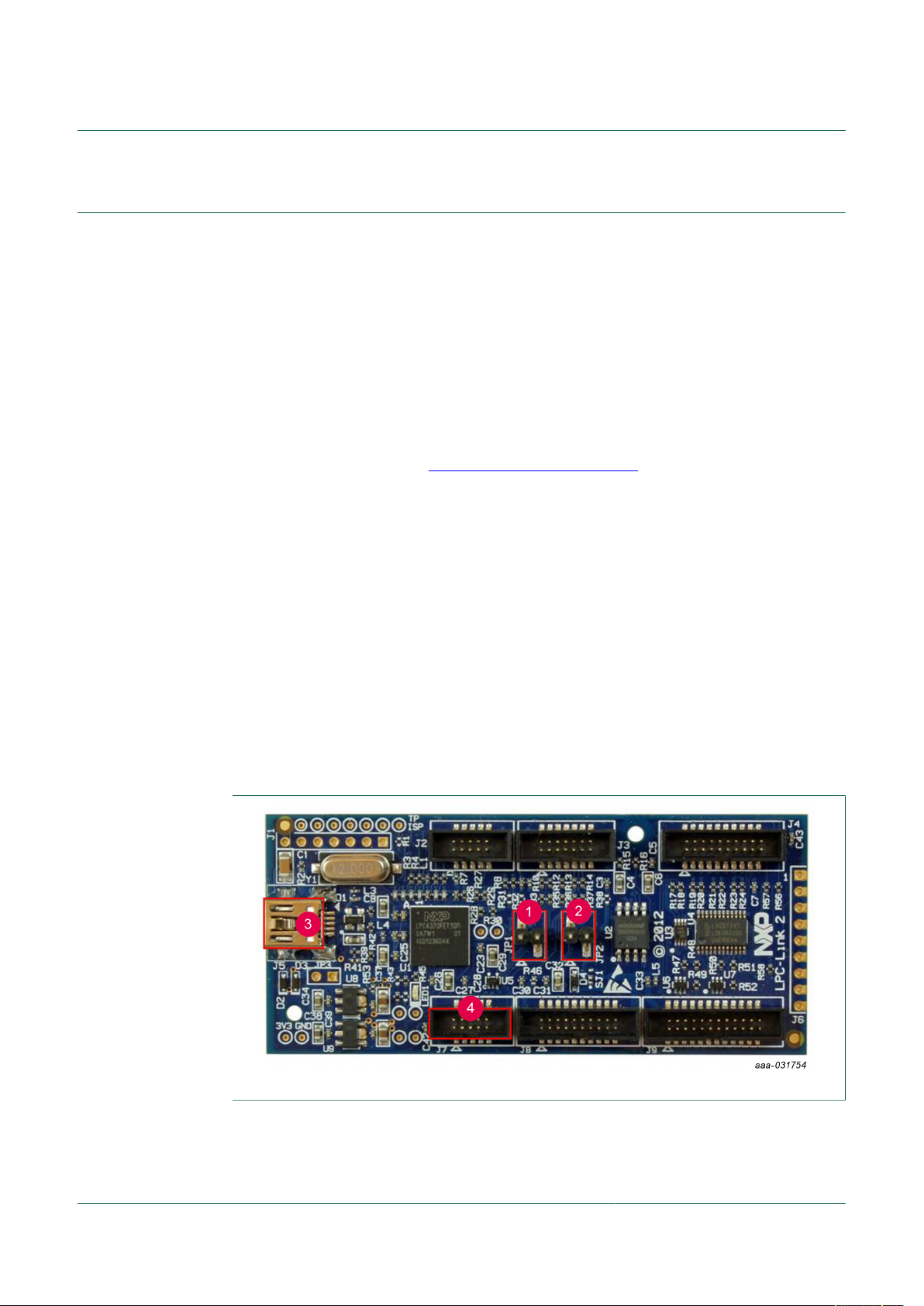
2.2.1 Physical setup
Before launching Flash Magic, be sure that the HW is correctly connected:
1. No jumper may be placed over JP1.
2. A jumper must be placed over JP2.
3. Connect the LPC-Link2 board with your PC using a mini-USB cable.
4. Connect the demo PCB with the LPC-Link2 board using a JTAG cable.
Figure 1. NHS31xx Downloader - Step 1
UM11154 All information provided in this document is subject to legal disclaimers. © NXP B.V. 2020. All rights reserved.
User manual Rev. 2.02 — 14 August 2020
4 / 14
Page 5

NXP Semiconductors
Warning: Flash Magic cannot program via the LPC-Link2 debugger board if:
• The LPC-Link2 board is not connected when Flash Magic is started.
• The LPC-Link2 board is running a CMSIS-DAP debugger firmware other than the
customized version used by Flash Magic.
If Flash Magic cannot find your LPC-Link2 board, check your setup, power cycle the
board, and restart Flash Magic.
2.2.2 GUI settings
Settings are remembered between sessions. Nonetheless, it is advised to check each
setting each time before attempting to flash.
1. Select the NHS31xx IC you want to program.
2. Select the SWD over Link2 Interface.
3. Safest is to erase all Flash sectors.
4. Make sure that you select the correct firmware image, in Intel HEX format. Images
5. With the Execute checkbox ticked, the IC will reset and start executing the new
6. When all settings are correct, click Start to carry out the requested operations.
UM11154
NTAG SmartSensor getting started:
Reprogramming an NHS31xx using Flash Magic
Other settings in the communications step are ignored.
can be obtained via:
• The download links to the different demo applications provided in the next chapter.
• The SDK, in the Debug and Release subfolders of each provided demo and
example application.
• The LPCXpresso IDE, where you compile your own application.
firmware immediately after programming has finished.
UM11154 All information provided in this document is subject to legal disclaimers. © NXP B.V. 2020. All rights reserved.
User manual Rev. 2.02 — 14 August 2020
5 / 14
Page 6

NXP Semiconductors
UM11154
NTAG SmartSensor getting started:
Reprogramming an NHS31xx using Flash Magic
Figure 2. Flash Magic GUI settings
UM11154 All information provided in this document is subject to legal disclaimers. © NXP B.V. 2020. All rights reserved.
User manual Rev. 2.02 — 14 August 2020
6 / 14
Page 7

NXP Semiconductors
3 Boards
The images suitable for wired download, using the external Windows tool Flash Magic,
are all in Intel Hex (.hex) format. Use the download links below to store them locally on
your PC.
3.1 NHS3100 temperature monitor board
UM11154
NTAG SmartSensor getting started:
Reprogramming an NHS31xx using Flash Magic
Figure 3. NHS3100TEMODB
• Temperature Logger demo. Active demo (requires a battery). To be used with the
NHS3100 Temperature Logger app, available in the Google Play Store and the Apple
APP store.
Firmware: tlogger.hex
• Signed URL demo. Passive demo (requires removing the battery after flashing). To be
used with the NHS31xx Signed URL app, available in the Google Play Store and the
Apple APP store.
Firmware: signedurl.hex
• Blinky. A basic Hello World image, which continually toggles an LED and nothing else.
Firmware: blinky.hex (LED on PIO7)
UM11154 All information provided in this document is subject to legal disclaimers. © NXP B.V. 2020. All rights reserved.
User manual Rev. 2.02 — 14 August 2020
7 / 14
Page 8

NXP Semiconductors
3.2 NHS3100 - UCODE-I2C solution board
Figure 4. NHS3100UCODEDB
• Temperature Logger demo with logistics status reporting. To be used with the
NHS3100 Temperature Logger app, available in the Google Play Store and the Apple
APP store; and the NHS3100 UCode-I2C combo application for Windows and macOS,
available in the SDK under sw/crossplatform/tloggerucode.
Firmware: tloggerucode.hex
• Blinky. A basic Hello World image, which continually toggles an LED and nothing else.
Firmware: blinky.hex (LED on PIO8)
UM11154
NTAG SmartSensor getting started:
Reprogramming an NHS31xx using Flash Magic
UM11154 All information provided in this document is subject to legal disclaimers. © NXP B.V. 2020. All rights reserved.
User manual Rev. 2.02 — 14 August 2020
8 / 14
Page 9

NXP Semiconductors
3.3 NHS3100 sensor board
Figure 5. NHS3100SENSORDB
UM11154
NTAG SmartSensor getting started:
Reprogramming an NHS31xx using Flash Magic
• Sensor monitor demo combining temperature, shocks, tilting, and humidity with
logistics status reporting. To be used with the NHS3100 Sensor Board Monitor app,
available in the Google Play Store and the Apple APP store; and the NHS3100UCodeI2C combo application for Windows and macOS, available in the SDK under sw/
crossplatform/tloggerucode.
Firmware: sensorboard.hex
• Sensor monitor demo combining temperature and vibrations for preventive
maintenance scheduling in an Industry 4.0 environment. To be used with the
NHS3100 Sensor Button Monitor app, available in the Google Play Store and the Apple
APP store.
Firmware: sensorbutton.hex
UM11154 All information provided in this document is subject to legal disclaimers. © NXP B.V. 2020. All rights reserved.
User manual Rev. 2.02 — 14 August 2020
9 / 14
Page 10

NXP Semiconductors
3.4 NHS3100 therapy adherence board
Figure 6. NHS3100THADDB
• Therapy Adherence demo (using 14 switches and 8 digital pins). To be used with the
NXP Therapy Config, available in the Google Play Store.
Firmware: tadherence.hex (using PIOs)
• Blinky. A basic Hello World image, which continually toggles an LED and nothing else.
Firmware: blinky.hex (LED on PIO7)
UM11154
NTAG SmartSensor getting started:
Reprogramming an NHS31xx using Flash Magic
UM11154 All information provided in this document is subject to legal disclaimers. © NXP B.V. 2020. All rights reserved.
User manual Rev. 2.02 — 14 August 2020
10 / 14
Page 11

NXP Semiconductors
3.5 NHS3152 therapy adherence board
UM11154
NTAG SmartSensor getting started:
Reprogramming an NHS31xx using Flash Magic
Figure 7. NHS3152THADDB
• Therapy adherence demo (using 13 switches and 6 analog pins). To be used with the
NXP Therapy Config, available in the Google Play Store.
Firmware: tadherence.hex (using ANAs)
• Blinky. A basic Hello World image, which continually toggles an LED and nothing else.
Firmware: blinky.hex (LED on PIO7)
UM11154 All information provided in this document is subject to legal disclaimers. © NXP B.V. 2020. All rights reserved.
User manual Rev. 2.02 — 14 August 2020
11 / 14
Page 12

NXP Semiconductors
3.6 NHS3152 board
Figure 8. NHS3152DB
UM11154
NTAG SmartSensor getting started:
Reprogramming an NHS31xx using Flash Magic
No demo application has been created that specifically targets this board. It is intended
purely as a development board, providing easy access to all pins. Use this board to
integrate the NHS3152 IC with custom external components and sensors.
UM11154 All information provided in this document is subject to legal disclaimers. © NXP B.V. 2020. All rights reserved.
User manual Rev. 2.02 — 14 August 2020
12 / 14
Page 13

NXP Semiconductors
4 Legal information
4.1 Definitions
Draft — The document is a draft version only. The content is still under
internal review and subject to formal approval, which may result in
modifications or additions. NXP Semiconductors does not give any
representations or warranties as to the accuracy or completeness of
information included herein and shall have no liability for the consequences
of use of such information.
4.2 Disclaimers
Limited warranty and liability — Information in this document is believed
to be accurate and reliable. However, NXP Semiconductors does not
give any representations or warranties, expressed or implied, as to the
accuracy or completeness of such information and shall have no liability
for the consequences of use of such information. NXP Semiconductors
takes no responsibility for the content in this document if provided by an
information source outside of NXP Semiconductors. In no event shall NXP
Semiconductors be liable for any indirect, incidental, punitive, special or
consequential damages (including - without limitation - lost profits, lost
savings, business interruption, costs related to the removal or replacement
of any products or rework charges) whether or not such damages are based
on tort (including negligence), warranty, breach of contract or any other
legal theory. Notwithstanding any damages that customer might incur for
any reason whatsoever, NXP Semiconductors’ aggregate and cumulative
liability towards customer for the products described herein shall be limited
in accordance with the Terms and conditions of commercial sale of NXP
Semiconductors.
Right to make changes — NXP Semiconductors reserves the right to
make changes to information published in this document, including without
limitation specifications and product descriptions, at any time and without
notice. This document supersedes and replaces all information supplied prior
to the publication hereof.
Suitability for use — NXP Semiconductors products are not designed,
authorized or warranted to be suitable for use in life support, life-critical or
safety-critical systems or equipment, nor in applications where failure or
malfunction of an NXP Semiconductors product can reasonably be expected
to result in personal injury, death or severe property or environmental
damage. NXP Semiconductors and its suppliers accept no liability for
inclusion and/or use of NXP Semiconductors products in such equipment or
applications and therefore such inclusion and/or use is at the customer’s own
risk.
Applications — Applications that are described herein for any of these
products are for illustrative purposes only. NXP Semiconductors makes
no representation or warranty that such applications will be suitable
for the specified use without further testing or modification. Customers
are responsible for the design and operation of their applications and
products using NXP Semiconductors products, and NXP Semiconductors
accepts no liability for any assistance with applications or customer product
design. It is customer’s sole responsibility to determine whether the NXP
Semiconductors product is suitable and fit for the customer’s applications
and products planned, as well as for the planned application and use of
UM11154
NTAG SmartSensor getting started:
Reprogramming an NHS31xx using Flash Magic
customer’s third party customer(s). Customers should provide appropriate
design and operating safeguards to minimize the risks associated with
their applications and products. NXP Semiconductors does not accept any
liability related to any default, damage, costs or problem which is based
on any weakness or default in the customer’s applications or products, or
the application or use by customer’s third party customer(s). Customer is
responsible for doing all necessary testing for the customer’s applications
and products using NXP Semiconductors products in order to avoid a
default of the applications and the products or of the application or use by
customer’s third party customer(s). NXP does not accept any liability in this
respect.
Export control — This document as well as the item(s) described herein
may be subject to export control regulations. Export might require a prior
authorization from competent authorities.
Evaluation products — This product is provided on an “as is” and “with all
faults” basis for evaluation purposes only. NXP Semiconductors, its affiliates
and their suppliers expressly disclaim all warranties, whether express,
implied or statutory, including but not limited to the implied warranties of
non-infringement, merchantability and fitness for a particular purpose. The
entire risk as to the quality, or arising out of the use or performance, of this
product remains with customer. In no event shall NXP Semiconductors, its
affiliates or their suppliers be liable to customer for any special, indirect,
consequential, punitive or incidental damages (including without limitation
damages for loss of business, business interruption, loss of use, loss of
data or information, and the like) arising out the use of or inability to use
the product, whether or not based on tort (including negligence), strict
liability, breach of contract, breach of warranty or any other theory, even if
advised of the possibility of such damages. Notwithstanding any damages
that customer might incur for any reason whatsoever (including without
limitation, all damages referenced above and all direct or general damages),
the entire liability of NXP Semiconductors, its affiliates and their suppliers
and customer’s exclusive remedy for all of the foregoing shall be limited to
actual damages incurred by customer based on reasonable reliance up to
the greater of the amount actually paid by customer for the product or five
dollars (US$5.00). The foregoing limitations, exclusions and disclaimers
shall apply to the maximum extent permitted by applicable law, even if any
remedy fails of its essential purpose.
Translations — A non-English (translated) version of a document is for
reference only. The English version shall prevail in case of any discrepancy
between the translated and English versions.
Security — While NXP Semiconductors has implemented advanced
security features, all products may be subject to unidentified vulnerabilities.
Customers are responsible for the design and operation of their applications
and products to reduce the effect of these vulnerabilities on customer’s
applications and products, and NXP Semiconductors accepts no liability for
any vulnerability that is discovered. Customers should implement appropriate
design and operating safeguards to minimize the risks associated with their
applications and products.
4.3 Trademarks
Notice: All referenced brands, product names, service names and
trademarks are the property of their respective owners.
UM11154 All information provided in this document is subject to legal disclaimers. © NXP B.V. 2020. All rights reserved.
User manual Rev. 2.02 — 14 August 2020
13 / 14
Page 14

NXP Semiconductors
Contents
1 Introduction ......................................................... 3
2 Flash Magic ......................................................... 4
2.1 Installation ..........................................................4
2.2 Usage .................................................................4
2.2.1 Physical setup ................................................... 4
2.2.2 GUI settings .......................................................5
3 Boards .................................................................. 7
3.1 NHS3100 temperature monitor board ................7
3.2 NHS3100 - UCODE-I2C solution board ............. 8
3.3 NHS3100 sensor board .....................................9
3.4 NHS3100 therapy adherence board ................ 10
3.5 NHS3152 therapy adherence board ................ 11
3.6 NHS3152 board ............................................... 12
4 Legal information .............................................. 13
UM11154
NTAG SmartSensor getting started:
Reprogramming an NHS31xx using Flash Magic
Please be aware that important notices concerning this document and the product(s)
described herein, have been included in section 'Legal information'.
© NXP B.V. 2020. All rights reserved.
For more information, please visit: http://www.nxp.com
For sales office addresses, please send an email to: salesaddresses@nxp.com
Date of release: 14 August 2020
Document identifier: UM11154
 Loading...