

Page 1
NXP universal LED driver
UBA3070
Driving LED strings made simple
Light-up your LCD TV or monitor with the NXP universal LED driver UBA3070. This versatile,
high-voltage LED control IC is specifi cally designed for applications where large numbers of LEDs
have to be driven accurately and effi ciently. So it’s the perfect choice for LCD backlighting systems.
Key features
Ñ
Switch-mode buck converter capable of driving
LED strings up to 600 V
Ñ
Direct PWM dimming
Ñ
Fast transient response through cycle-by-cycle
current control
- Prevents LED current over- and undershoots
Ñ
Zero-current switching for turn-on of switch
Ñ
Zero-voltage or valley switching for turn-on of switch
Ñ
Over-current and over-temperature protection,
under-voltage lockout and leading edge blanking
Ñ
Available in DIP8 and SO8 packages
Key benefi ts
Ñ
Low system cost
Ñ
Reduced component count
Ñ
Power-effi cient boundary conduction mode of operation
- No reverse recovery losses in freewheel diode
- Requires smaller, lower-valued inductor
Ñ
No LED binning on forward voltage required
Ñ
Allows use of a single, loosely controlled input voltage
for multiple LED strings
Key applications
Ñ
High-voltage backlighting in LCD TVs and monitors
Page 2
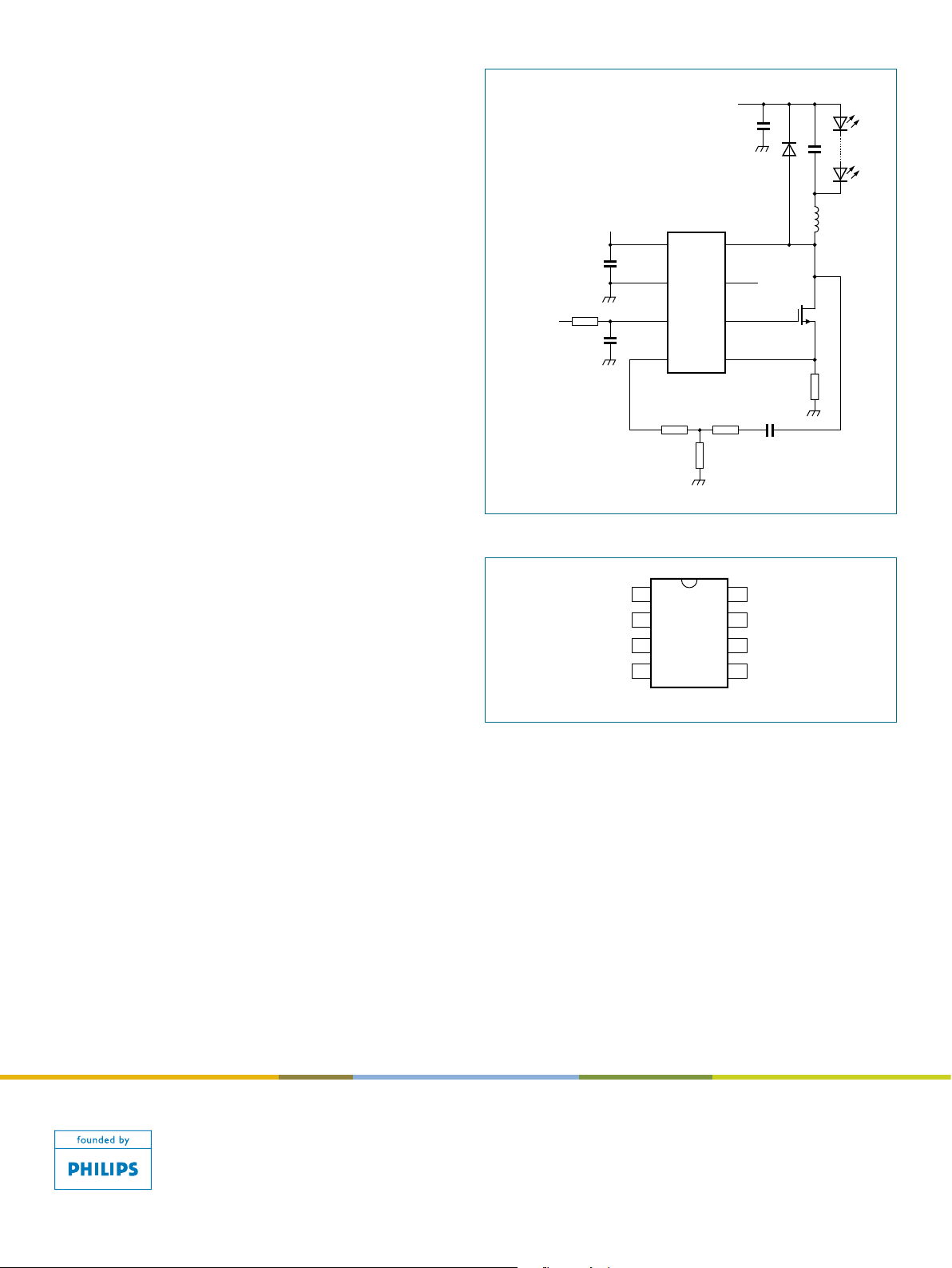
The UBA3070 is an integrated switch-mode buck converter
UBA3070
V
CC
DRAIN
GND
HVS
PWM
GATE
MASK
R
sense
bra975
1
2
3
4
6
5
8
7
bra976
12 V
V
CC
V
in
1
GND
2
PWM
PWM1 3
MASK
4
DRAIN
HVS
GATE
R
sense
8
7
6
5
for controlling the current through LED strings. Ideal as the
driver stage for LCD backlighting applications, it enables
optimal performance for series-connected LED strings in 0D,
1D and 2D segmented backlight units (BLUs).
As the UBA3070 drives an external power device, it can be
used for all kinds of BLU designs from high- to low-power
LEDs, and high- to low-voltage LED strings. Consequently,
it can be used with all LCD screen sizes and all LED types.
And by combining the UBA3070 with appropriate power
devices, you can minimize the number of driver stages
needed by optimizing the number of LEDs connected in series.
Each driver stage consists of a buck converter operating
in boundary conduction mode. Its peak level can be set
through the external sense resistor. As the zero-level is fixed,
the converter acts as a current source with an average current
through the LED of half the peak value through the inductor.
The ripple current through the LEDs can be chosen via the
external capacitor connected in parallel to the LEDs.
Basic application diagram
www.nxp.com
Pin configuration (SO8 and DIP8)
© 2007 NXP B.V.
All rights reser ved. Reproduc tion i n who le or in part is p rohibited witho ut the prio r wri tten consent of t he co pyright owner.
The informat ion pre sented in thi s docu ment d oes not form part of an y quota tion o r contr act, is beli eved to be accurate and
reliab le an d may be change d wi thout notice. No liabilit y wi ll be acce pted by th e pu blisher for any conseque nce of it s us e.
Public ation there of does not conv ey nor imply any l icense unde r patent- or othe r industri al or intellec tual proper ty right s.
Date of rel ease: April 2 007
Docum ent order num ber: 9397 750 160 07
Printe d in the Nether lands
 Loading...