

Page 1

NXP Semiconductors Document identifier: S32GVNPRDBUG
User's Guide Rev. 2, March, 2021
S32G-VNP-RDB User Guide
Page 2

NXP Semiconductors
Contents
Chapter 1 Introduction........................................................................................... 3
Chapter 2 S32G-VNP-RDB Features.................................................................... 4
Chapter 3 Hardware Package Overview................................................................6
Chapter 4 Switch Settings......................................................................................7
Chapter 5 S32G-VNP-RDB Pinouts.....................................................................10
Chapter 6 S32G-VNP-RDB Set Up......................................................................13
Chapter 7 Revision history...................................................................................14
Appendix A Appendix...........................................................................................15
S32G-VNP-RDB User Guide, Rev. 2, March, 2021
User's Guide 2 / 16
Page 3
NXP Semiconductors
Chapter 1
Introduction
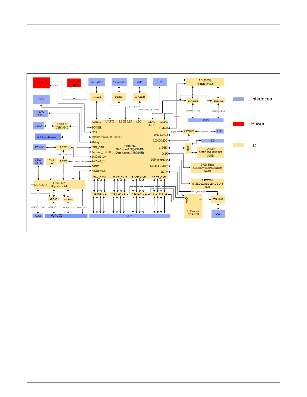
This user guide gives an overview of S32G-VNP-RDB reference design. The following figure shows the block diagram.
Figure 1. S32G-VNP-RDB block diagram
S32G-VNP-RDB User Guide, Rev. 2, March, 2021
User's Guide 3 / 16
Page 4
NXP Semiconductors
Chapter 2
S32G-VNP-RDB Features
The following are the S32G-VNP-RDB features.
• Reference design for Service-oriented gateway and domain controller applications
• Multiple network interfaces - features 16 CAN/CAN FD and 14 Ethernet ports
• Entire board supports low power mode and wake-up mechanisms, including CAN, FlexRay , Ethernet, internal RTC and
external wake up sources
• Two Ethernet switches (SJA1105, SJA1110A) provides a variety of types of interfaces , such as 100BASE-T1, 100BASETX,1000BASE-T. secure CAN PHY (TJA1153) supporting black/white list and preventing flooding on CAN bus. CAN PHY
TJA1463 can eliminate ringing on communication
• Function safety supporting, includes:
— ASIL D S32G274A vehicle network processor
— ASIL D VR5510 power management IC
— ASIL A SJA1105Q and SJA1110A Ethernet switches
— Fault management and reset logic circuits
• Using automotive-qualified connectors
— TE Connectivity MATEnet and Tyco Electronics 40p HDR
• Multiple PCIe interfaces to support 2.5G SGMII, SSD and Wi-Fi card
• Entire board supports environment temperature -40 °C to +70 °C
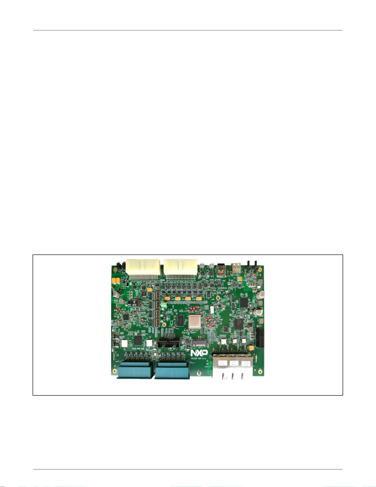
Figure 2. S32G-VNP-RDB board
The following are the board features:
• 1 x NOR flash( 64MB )
• 1 x SD card slot/ eMMC (32GB)
• 1 x LPDDR4 (4GB)
• 1 x 100BASE-TX
S32G-VNP-RDB User Guide, Rev. 2, March, 2021
User's Guide 4 / 16
Page 5

NXP Semiconductors
• 10 x 100BASE-T1
• 3 x 1000BASE-T
• 1 x M.2 slot support for SSD
• 1 x PCIe X1 slot
• 1 x USB 2.0 port as host mode
• 12 x LLCE CAN/CAN FD
• 4 x FlexCAN /CAN FD
• 4 x LLCE LIN
• 1 x LLCE FlexRay
• 1 x LLCE SPI interface
• 1 x I2C interface
• 1 x 20-pin debug port
• 2 x UART
• 5 x ADC with 12-bit resolution
• 1 x External wake-up source
S32G-VNP-RDB Features
[1]
• 2 x External interrupts
• 2 x PWMal
[1] NVMe SSD needs to be ordered separately. Please note that Netac N930ES-128GB NVMe SSD is already tested
on S32G-VNP-RDB.
S32G-VNP-RDB User Guide, Rev. 2, March, 2021
User's Guide 5 / 16
Page 6

NXP Semiconductors
Chapter 3
Hardware Package Overview
The following section describes the hardware package overview of S32G-VNP-RDB. The following hardware and accessories are
needed as shown in the following figure.
Figure 3. S32G-VNP-RDB hardware and accessories
3.1 Hardware connection instruction
To connect any cable to RDB, follow the instructions shown in the following figure.
Figure 4. Connection instruction
S32G-VNP-RDB User Guide, Rev. 2, March, 2021
User's Guide 6 / 16
Page 7

NXP Semiconductors
Chapter 4
Switch Settings
4.1 S32G-VNP-RDB default switch settings
The following figure shows the default switch settings of S32G-VNP-RDB.
Figure 5. Default switch settings
NOTE
The default boot mode is set to boot from SD card.
4.2 Switch settings for SD card boot
The following figure shows the switch settings for SD card boot.
S32G-VNP-RDB User Guide, Rev. 2, March, 2021
User's Guide 7 / 16
Page 8

NXP Semiconductors
Figure 6. SD bard boot switch settings
Switch Settings
4.3 Switch settings for eMMC boot
The following figure shows the switch settings for eMMC boot.
Figure 7. eMMC boot switch settings
4.4 Switch settings for NOR Flash boot
The following figure shows the switch settings for NOR Flash boot.
S32G-VNP-RDB User Guide, Rev. 2, March, 2021
User's Guide 8 / 16
Page 9

NXP Semiconductors
Figure 8. NOR Flash boot switch settings
Switch Settings
S32G-VNP-RDB User Guide, Rev. 2, March, 2021
User's Guide 9 / 16
Page 10

NXP Semiconductors
Chapter 5
S32G-VNP-RDB Pinouts
The following figure and table shows the different S32G-VNP-RDB pinouts.
Figure 9. S32G-VNP-RDB pinouts
Table 1. S32G-VNP-RDB pinouts and signals
Part Reference Signals
J1 UART1
J2 UART0
J3 SD Card Slot
J4 USB 2.0 as host mode
J5 12V input, 12V, 5V, 3.3V output, GPIO, PWM, I2C,
LLCE_FlexRay , LLCE_SPI, LLCE_LIN
J6 LLCE_CAN, FlexCAN , ADC
Table continues on the next page...
S32G-VNP-RDB User Guide, Rev. 2, March, 2021
User's Guide 10 / 16
Page 11

NXP Semiconductors
Table 1. S32G-VNP-RDB pinouts and signals (continued)
Part Reference Signals
J44 10PIN JTAG for SJA1110
J47 M.2 slot for 2242 SSD
J48 20PIN JTAG for S32G
J50 12V FAN
J52 1000BASE-T, 100BASE-TX
J53 100BASE-T1
J54 100BASE-T1
P1 PCI e Gen3 X1
CAN, ADC, POWER, GPIO, LLCE_FlexRay and LLCE_LIN pinout.
S32G-VNP-RDB Pinouts
The following figure shows the Ethernet pinouts.
S32G-VNP-RDB User Guide, Rev. 2, March, 2021
User's Guide 11 / 16
Page 12

NXP Semiconductors
S32G-VNP-RDB Pinouts
S32G-VNP-RDB User Guide, Rev. 2, March, 2021
User's Guide 12 / 16
Page 13

NXP Semiconductors
Chapter 6
S32G-VNP-RDB Set Up
To set up S32G-VNP-RDB follow these steps:
1. Download and Install the terminal emulator, if not installed already.
About the terminal tool, you can choose any one which is familiar for you, such as Tera Term, Putty and so on.
2. Download and Install the FT232R USB-to-UART driver, if not installed already. Go to FT232R USB-to-UART driver
link .Scroll down and select correct version. Follow the installation guides to install the driver.
3. Plug the SD card in the J3 slot. The SD card has pre-loaded Linux BSP image which runs on Cortex-A53 cores.
4. Connect UART0 cable and open terminal console. Select the corresponding COM port which can be found in “Device
Manager” of the PC and set 115200 as the baud rate.
5. Connect the power supply and J5 cable. Open the switch of power switch board, the running logs will appear in the console
as shown below.
NOTE
For more information on S32G boot, such as other boot mode, building project, making image and so on, refer to
S32G-VNP-RDB Reference Manual and S32G-VNP-RDB Software Enablement Guide.
S32G-VNP-RDB User Guide, Rev. 2, March, 2021
User's Guide 13 / 16
Page 14

NXP Semiconductors
Chapter 7
Revision history
Table 2. Revision history
Revision Number Release date Changes
0 June, 2020 Intitial release
1 November, 2020 Editorial fixes
2 March, 2021
• Updated the figure in S32G-VNP-
RDB Set Up.
• Removed the section Running logs
of applications.
S32G-VNP-RDB User Guide, Rev. 2, March, 2021
User's Guide 14 / 16
Page 15

NXP Semiconductors
Appendix A
Appendix
• Documents
— S32G Data Sheet
— S32G Reference Manual
— S32G-VNP-RDB Factsheet
— S32G-VNP-RDB Reference Manual
— S32G-VNP-RDB Software Enablement Guide
— Auto_Linux_BSP_XX.X_S32G274A_User_Manual
— Auto_Linux_BSP_XX.X_S32G274A_Quick_Start
• Useful links
— S32 Design Studio
— S32 Debug Probe
• Support https://community.nxp.com/
• Enablement Tools
— IDE: S32 Design Studio, Yocto , EB tresos
— Software: Linux BSP, FreeRTOS , Real-Time Drivers(RTD)
— Compiler: Green Hills, gcc
— Debugger: Lauterbach, S32G Debug Probe
S32G-VNP-RDB User Guide, Rev. 2, March, 2021
User's Guide 15 / 16
Page 16

How To Reach Us
Home Page:
nxp.com
Web Support:
nxp.com/support
Information in this document is provided solely to enable system and software implementers
to use NXP products. There are no express or implied copyright licenses granted hereunder
to design or fabricate any integrated circuits based on the information in this document. NXP
reserves the right to make changes without further notice to any products herein.
NXP makes no warranty, representation, or guarantee regarding the suitability of its products
for any particular purpose, nor does NXP assume any liability arising out of the application
or use of any product or circuit, and specifically disclaims any and all liability, including
without limitation consequential or incidental damages. “Typical” parameters that may be
provided in NXP data sheets and/or specifications can and do vary in different applications,
and actual performance may vary over time. All operating parameters, including “typicals,”
must be validated for each customer application by customer's technical experts. NXP does
not convey any license under its patent rights nor the rights of others. NXP sells products
pursuant to standard terms and conditions of sale, which can be found at the following address:
nxp.com/SalesTermsandConditions.
While NXP has implemented advanced security features, all products may be subject to
unidentified vulnerabilities. Customers are responsible for the design and operation of their
applications and products to reduce the effect of these vulnerabilities on customer’s applications
and products, and NXP accepts no liability for any vulnerability that is discovered. Customers
should implement appropriate design and operating safeguards to minimize the risks associated
with their applications and products.
NXP, the NXP logo, NXP SECURE CONNECTIONS FOR A SMARTER WORLD, COOLFLUX,
EMBRACE, GREENCHIP, HITAG, I2C BUS, ICODE, JCOP, LIFE VIBES, MIFARE, MIFARE
CLASSIC, MIFARE DESFire, MIFARE PLUS, MIFARE FLEX, MANTIS, MIFARE ULTRALIGHT,
MIFARE4MOBILE, MIGLO, NTAG, ROADLINK, SMARTLX, SMARTMX, STARPLUG, TOPFET,
TRENCHMOS, UCODE, Freescale, the Freescale logo, AltiVec, C‑5, CodeTEST, CodeWarrior,
ColdFire, ColdFire+, C‑Ware, the Energy Efficient Solutions logo, Kinetis, Layerscape, MagniV,
mobileGT, PEG, PowerQUICC, Processor Expert, QorIQ, QorIQ Qonverge, Ready Play,
SafeAssure, the SafeAssure logo, StarCore, Symphony, VortiQa, Vybrid, Airfast, BeeKit,
BeeStack, CoreNet, Flexis, MXC, Platform in a Package, QUICC Engine, SMARTMOS, Tower,
TurboLink, and UMEMS are trademarks of NXP B.V. All other product or service names
are the property of their respective owners. AMBA, Arm, Arm7, Arm7TDMI, Arm9, Arm11,
Artisan, big.LITTLE, Cordio, CoreLink, CoreSight, Cortex, DesignStart, DynamIQ, Jazelle, Keil,
Mali, Mbed, Mbed Enabled, NEON, POP, RealView, SecurCore, Socrates, Thumb, TrustZone,
ULINK, ULINK2, ULINK-ME, ULINK-PLUS, ULINKpro, µVision, Versatile are trademarks or
registered trademarks of Arm Limited (or its subsidiaries) in the US and/or elsewhere. The related
technology may be protected by any or all of patents, copyrights, designs and trade secrets. All
rights reserved. Oracle and Java are registered trademarks of Oracle and/or its affiliates. The
Power Architecture and Power.org word marks and the Power and Power.org logos and related
marks are trademarks and service marks licensed by Power.org.
©
NXP B.V. 2021. All rights reserved.
For more information, please visit: http://www.nxp.com
For sales office addresses, please send an email to: salesaddresses@nxp.com
Date of release: March, 2021
Document identifier: S32GVNPRDBUG
 Loading...