

Page 1

NXP Semiconductors Document identifier: OpenILUG
User's Guide Rev. 1.10, 12/2020
Open Industrial User Guide
Page 2

NXP Semiconductors
Contents
Chapter 1 Introduction........................................................................................... 8
1.1 Acronyms and abbreviations..................................................................................................... 8
1.2 Reference documentation......................................................................................................... 9
1.3 About OpenIL.......................................................................................................................... 10
1.3.1 OpenIL Organization................................................................................................................. 10
1.4 Supported NXP platforms and configurations......................................................................... 12
1.4.1 Default compilation settings for NXP platforms.........................................................................13
Chapter 2 Getting started.....................................................................................15
2.1 Getting OpenIL........................................................................................................................ 15
2.2 OpenIL quick start................................................................................................................... 15
2.2.1 Host system requirements........................................................................................................ 15
2.2.2 Creating RAMDISK file system................................................................................................. 17
2.2.3 Resizing second partition.......................................................................................................... 17
2.2.4 Customing Ubuntu file system.................................................................................................. 19
2.2.5 Building the images...................................................................................................................20
2.2.6 Troubleshooting........................................................................................................................ 23
2.3 Booting the board.................................................................................................................... 24
2.3.1 SD card bootup......................................................................................................................... 25
2.3.2 QSPI/FlexSPI bootup................................................................................................................ 25
2.3.3 eMMC bootup............................................................................................................................25
2.3.4 Starting up the board.................................................................................................................27
2.4 Basic OpenIL operations......................................................................................................... 28
2.4.1 Building Linux kernel................................................................................................................. 30
2.4.2 Building U-Boot......................................................................................................................... 31
Chapter 3 NXP OpenIL platforms........................................................................ 33
3.1 Introduction..............................................................................................................................33
3.2 LS1021A-TSN......................................................................................................................... 33
3.2.1 Switch settings.......................................................................................................................... 33
3.2.2 Updating target images ............................................................................................................ 33
3.3 LS1021A-TWR........................................................................................................................ 34
3.3.1 Switch settings.......................................................................................................................... 34
3.3.2 Updating target images ............................................................................................................ 34
3.4 LS1021A-IoT........................................................................................................................... 35
3.4.1 Switch settings ......................................................................................................................... 35
3.4.2 Updating target images ............................................................................................................ 35
3.5 LS1043ARDB, LS1046ARDB and LS1046AFRWY................................................................ 36
3.5.1 Switch settings.......................................................................................................................... 36
3.5.2 Updating target images ............................................................................................................ 36
3.6 LS1012ARDB.......................................................................................................................... 37
3.6.1 Switch settings.......................................................................................................................... 38
3.6.2 Updating target images ............................................................................................................ 38
3.7 i.MX6QSabreSD......................................................................................................................39
3.7.1 Switch settings for the i.MX6Q SabreSD.................................................................................. 39
3.7.2 Updating target images............................................................................................................. 39
3.8 LS1028ARDB and LS1028ATSN............................................................................................ 40
3.8.1 Switch settings.......................................................................................................................... 40
3.8.2 Interface naming....................................................................................................................... 40
Open Industrial User Guide, Rev. 1.10, 12/2020
User's Guide 2 / 263
Page 3

NXP Semiconductors
Contents
3.8.3 Updating target images............................................................................................................. 44
3.8.4 LCD controller and DisplayPort/eDP.........................................................................................45
3.9 LX2160ARDB/Rev2.................................................................................................................46
3.9.1 Switch settings.......................................................................................................................... 46
3.9.2 Updating target images ............................................................................................................ 46
3.10 i.MX8M Plus EVK.................................................................................................................. 47
3.10.1 Switch settings for the i.MX8MPEVK...................................................................................... 48
3.10.2 Updating target images .......................................................................................................... 48
3.11 i.MX8M Mini EVK...................................................................................................................48
3.11.1 Switch settings for the i.MX8MMEVK......................................................................................49
3.11.2 Updating target images........................................................................................................... 49
Chapter 4 Industrial features................................................................................50
4.1 Deterministic Network..............................................................................................................50
4.1.1 IEEE 1588/802.1AS.................................................................................................................. 50
4.1.2 TSN........................................................................................................................................... 50
4.2 Real Time................................................................................................................................ 50
4.2.1 PREEMPT-RT...........................................................................................................................50
4.2.2 Xenomai.................................................................................................................................... 51
4.2.3 Baremetal..................................................................................................................................51
4.3 Industrial Protocols..................................................................................................................51
4.3.1 EtherCAT.................................................................................................................................. 51
4.3.2 OPC-UA.................................................................................................................................... 51
4.3.3 FlexCAN....................................................................................................................................51
4.3.4 NFC...........................................................................................................................................51
4.3.5 BLE........................................................................................................................................... 52
4.3.6 BEE/ZigBEE..............................................................................................................................52
4.3.7 4G-LTE......................................................................................................................................52
4.4 Security....................................................................................................................................52
4.4.1 OP-TEE.....................................................................................................................................52
4.4.2 SELinux.....................................................................................................................................52
4.5 Remote Management..............................................................................................................52
4.5.1 NETCONF/YANG......................................................................................................................52
4.5.2 OTA...........................................................................................................................................53
4.5.3 EdgeScale client....................................................................................................................... 53
4.6 Display.....................................................................................................................................53
4.6.1 GPU...........................................................................................................................................53
4.6.2 Weston...................................................................................................................................... 54
4.6.3 QT............................................................................................................................................. 54
4.6.4 Camera..................................................................................................................................... 54
Chapter 5 IEEE 1588/802.1AS............................................................................ 55
5.1 Introduction..............................................................................................................................55
5.2 IEEE 1588 device types.......................................................................................................... 55
5.3 IEEE 802.1AS time-aware systems.........................................................................................56
5.4 Software stacks....................................................................................................................... 56
5.4.1 linuxptp stack............................................................................................................................ 56
5.4.2 NXP GenAVB/TSN gPTP stack................................................................................................ 57
5.5 Quick Start for IEEE 1588....................................................................................................... 57
5.5.1 Ordinary clock verification......................................................................................................... 57
5.5.2 Boundary clock verification....................................................................................................... 57
5.5.3 Transparent clock verification................................................................................................... 58
5.6 Quick Start for IEEE 802.1AS..................................................................................................58
Open Industrial User Guide, Rev. 1.10, 12/2020
User's Guide 3 / 263
Page 4

NXP Semiconductors
Contents
5.6.1 Time-aware end station verification.......................................................................................... 59
5.6.2 Time-aware bridge verification.................................................................................................. 59
5.7 Boundary clock jbod mode on LS1028ATSN.......................................................................... 60
5.8 Long term test..........................................................................................................................61
5.8.1 linuxptp basic synhronization.................................................................................................... 61
5.8.2 Boundary clock jbod mode on LS1028ATSN............................................................................63
5.9 Known issues and limitations.................................................................................................. 66
Chapter 6 Time Sensitive Network (TSN)............................................................67
6.1 TSN hardware capability......................................................................................................... 67
6.2 TSN configuration....................................................................................................................67
6.2.1 Using Linux traffic control (tc)....................................................................................................68
6.2.2 Using tsntool............................................................................................................................. 69
6.2.3 Remote configuration using NETCONF/YANG.........................................................................69
6.2.4 Remote configuration using Web UI......................................................................................... 70
6.3 Verifying TSN features on LS1028ARDB board......................................................................72
6.3.1 Tsntool User Manual................................................................................................................. 72
6.3.2 TSN configuration on ENETC................................................................................................... 82
6.3.3 TSN configuration on Felix switch.............................................................................................91
6.3.4 Q-in-Q configuration on Felix switch....................................................................................... 112
6.4 Verifying TSN features on LS1021A-TSN board...................................................................114
6.4.1 Topology................................................................................................................................. 114
6.4.2 SJA1105 Linux support........................................................................................................... 115
6.4.3 Synchronized 802.1Qbv demo................................................................................................118
6.5 Verifying TSN features on i.MX8MP board............................................................................123
6.5.1 Verifying TSN features on i.MX8MP board............................................................................. 123
Chapter 7 Preempt-RT.......................................................................................128
7.1 System RT Latency Tests..................................................................................................... 128
7.1.1 Running Cyclictest.................................................................................................................. 128
7.2 RT application development..................................................................................................128
Chapter 8 Xenomai............................................................................................ 130
8.1 Xenomai running mode......................................................................................................... 130
8.1.1 Running Xenomai Mercury......................................................................................................130
8.1.2 Running Cobalt mode............................................................................................................. 130
8.2 RTnet ....................................................................................................................................132
8.2.1 Hardware requirements...........................................................................................................132
8.2.2 Software requirements............................................................................................................ 132
8.2.3 Verifying RTnet....................................................................................................................... 135
Chapter 9 EtherCAT.......................................................................................... 136
9.1 Introduction............................................................................................................................136
9.2 IGH EtherCAT architecture....................................................................................................136
9.3 EtherCAT protocol.................................................................................................................137
9.4 EtherCAT system integration and example ..........................................................................138
9.4.1 Building kernel images for EtherCAT...................................................................................... 138
9.4.2 Command-line tool.................................................................................................................. 139
9.4.3 System integration.................................................................................................................. 140
9.4.4 Running a sample application................................................................................................. 142
9.5 NXP servo stack....................................................................................................................145
Open Industrial User Guide, Rev. 1.10, 12/2020
User's Guide 4 / 263
Page 5

NXP Semiconductors
Contents
9.5.1 CoE network............................................................................................................................145
9.5.2 Libnservo Architecture............................................................................................................ 146
9.5.3 Xml Configuration....................................................................................................................147
9.5.4 Test......................................................................................................................................... 151
9.6 EdgeScale client....................................................................................................................154
Chapter 10 OPC UA.......................................................................................... 156
10.1 OPC introduction................................................................................................................. 156
10.2 The node model...................................................................................................................156
10.3 Node Namespaces..............................................................................................................157
10.4 Node classes.......................................................................................................................158
10.5 Node graph and references.................................................................................................158
10.6 Open62541..........................................................................................................................159
Chapter 11 FlexCAN..........................................................................................161
11.1 Introduction..........................................................................................................................161
11.1.1 CAN bus................................................................................................................................161
11.1.2 CANopen...............................................................................................................................162
11.2 FlexCAN integration in OpenIL............................................................................................164
11.2.1 LS1021AIOT CAN resource allocation..................................................................................164
11.2.2 Introducing the function of CAN example code.....................................................................166
11.3 Running a CAN application................................................................................................. 167
11.3.1 Hardware preparation for LS1021-IoT.................................................................................. 167
11.3.2 Hardware preparation for LS1028ARDB...............................................................................168
11.3.3 Compiling the CANopen-app binary for the master node..................................................... 169
11.3.4 Running the CANopen application........................................................................................ 170
11.3.5 Running the Socketcan commands...................................................................................... 173
11.3.6 Testing CAN bus................................................................................................................... 173
Chapter 12 NFC.................................................................................................175
12.1 Introduction..........................................................................................................................175
12.2 PN7120 features..................................................................................................................175
12.3 Hardware preparation..........................................................................................................175
12.4 Software preparation........................................................................................................... 175
12.5 Testing the NFC click board................................................................................................ 176
Chapter 13 BLE................................................................................................. 178
13.1 Introduction..........................................................................................................................178
13.2 Features.............................................................................................................................. 178
13.3 Hardware preparation..........................................................................................................178
13.4 Software preparation........................................................................................................... 179
13.5 Testing the BLE P click board............................................................................................. 180
Chapter 14 BEE................................................................................................. 183
14.1 Introduction..........................................................................................................................183
14.2 Features.............................................................................................................................. 183
14.3 Hardware preparation..........................................................................................................183
14.4 Software preparation........................................................................................................... 184
14.5 Testing the BEE click board................................................................................................ 185
Open Industrial User Guide, Rev. 1.10, 12/2020
User's Guide 5 / 263
Page 6

NXP Semiconductors
Contents
Chapter 15 4G-LTE Modem ..............................................................................187
15.1 Introduction..........................................................................................................................187
15.2 Hardware preparation..........................................................................................................187
15.3 Software preparation........................................................................................................... 187
15.4 Testing 4G USB modem link to the internet........................................................................ 187
Chapter 16 OP-TEE...........................................................................................189
16.1 Introduction..........................................................................................................................189
16.2 Deployment architecture......................................................................................................189
16.3 DDR memory map...............................................................................................................190
16.4 Configuring OP-TEE on LS1021A-TSN platform.................................................................191
16.5 Running OP-TEE on LS1021A-TSN platform......................................................................192
16.5.1 Running secure boot............................................................................................................. 192
16.5.2 Executing Op-tee Daemon....................................................................................................192
16.5.3 Executing OP-Tee test cases................................................................................................193
Chapter 17 SELinux...........................................................................................194
17.1 Running SELinux demo.......................................................................................................194
17.1.1 Obtaining the image for SELinux.......................................................................................... 194
17.1.2 Installing basic packages...................................................................................................... 194
17.1.3 Basic setup............................................................................................................................197
17.1.4 Demo 1: local access control................................................................................................ 199
17.1.5 Demo 2: enabling remote access control..............................................................................202
Chapter 18 NETCONF/YANG............................................................................206
18.1 Overview..............................................................................................................................206
18.2 Netopeer2............................................................................................................................206
18.2.1 Overview............................................................................................................................... 206
18.2.2 Sysrepo................................................................................................................................. 207
18.2.3 Netopeer2 server.................................................................................................................. 207
18.2.4 Netopeer2 client.................................................................................................................... 207
18.2.5 Workflow in application practice............................................................................................208
18.3 Installing Netopeer2-cli on Ubuntu18.04............................................................................. 208
18.4 Configuration....................................................................................................................... 209
18.4.1 Enabling NETCONF feature in OpenIL................................................................................. 209
18.4.2 Netopeer2-server.................................................................................................................. 210
18.4.3 Netopeer2-cli ........................................................................................................................210
18.4.4 Sysrepod............................................................................................................................... 213
18.4.5 Sysrepocfg............................................................................................................................ 214
18.4.6 Sysrepoctl............................................................................................................................. 214
18.4.7 Operation examples.............................................................................................................. 215
18.4.8 Application scenarios............................................................................................................ 217
18.5 Web UI demo.......................................................................................................................220
18.6 Troubleshooting...................................................................................................................222
Chapter 19 OTA implementation....................................................................... 223
19.1 Introduction..........................................................................................................................223
19.2 Platform support for OTA demo...........................................................................................224
19.3 Server requirements............................................................................................................224
19.4 OTA test case......................................................................................................................225
Open Industrial User Guide, Rev. 1.10, 12/2020
User's Guide 6 / 263
Page 7

NXP Semiconductors
Contents
Chapter 20 EdgeScale client............................................................................. 226
20.1 What is EdgeScale.............................................................................................................. 226
20.2 Edgescale features..............................................................................................................226
20.3 Building EdgeScale client....................................................................................................226
20.4 Procedure to start EdgeScale..............................................................................................226
Chapter 21 Vivante GPU................................................................................... 228
Chapter 22 Weston............................................................................................ 232
Chapter 23 QT................................................................................................... 236
23.1 Introduction..........................................................................................................................236
23.2 Software settings and configuration.................................................................................... 236
23.3 Hardware setup................................................................................................................... 236
23.4 Running the QT5 demo....................................................................................................... 237
23.4.1 Environment setting.............................................................................................................. 237
23.4.2 Running the demos............................................................................................................... 237
Chapter 24 GenAVB/TSN stack.........................................................................240
24.1 Introduction..........................................................................................................................240
24.1.1 gPTP stack............................................................................................................................240
24.1.2 TSN Endpoint example application....................................................................................... 240
24.1.3 Supported configurations...................................................................................................... 241
24.2 Software preparation........................................................................................................... 241
24.3 GenAVB/TSN stack start/stop............................................................................................. 242
24.4 Use cases description......................................................................................................... 242
24.4.1 gPTP Bridge..........................................................................................................................242
24.4.2 gPTP Endpoint...................................................................................................................... 242
24.4.3 TSN endpoint sample application......................................................................................... 243
24.5 Configuration files................................................................................................................246
24.5.1 System.................................................................................................................................. 246
24.5.2 gPTP..................................................................................................................................... 247
24.6 Log files............................................................................................................................... 251
24.6.1 gPTP Endpoint...................................................................................................................... 251
24.6.2 gPTP Bridge..........................................................................................................................253
24.6.3 TSN Endpoint example application....................................................................................... 254
Chapter 25 Camera........................................................................................... 256
Chapter 26 Revision history...............................................................................260
Open Industrial User Guide, Rev. 1.10, 12/2020
User's Guide 7 / 263
Page 8

NXP Semiconductors
Chapter 1
Introduction
This document provides a complete description of Open Industrial Linux (OpenIL) features, getting started on OpenIL using
NXP OpenIL platforms, and the various software settings involved. It describes in detail the industrial features, which include
NETCONF/YANG, TSN, Xenomai, Preempt-RT, IEEE 1588, OP-TEE, and SELinux. It also includes detailed steps for running the
demos such as Selinux demo, 1-board TSN Demo, 3-board TSN demo, 4G-LTE demo, OTA implementation, BLE Click Board
and BEE Click Board. It also provides a complete description of the OpenIL compilation steps.
1.1 Acronyms and abbreviations
The following table lists the acronyms used in this document.
Table 1. Acronyms and abbreviations
Term Description
AVB Audio Video Bridging
BC Boundary clock
BLE Bluetooth low energy
BMC Best master clock
CA Client application
CAN Controller area network
DEI Drop eligibility indication
DP Display port
EtherCAT Ethernet for control automation technology
FMan Frame manager
GPU General Proccesor Unit
ICMP Internet control message protocol
IEEE Institute of electrical and electronics engineers
IETF Internet engineering task force
IPC Inter process communication
KM Key management
LBT Latency and bandwidth tester
MAC Medium access control
NFC Near field communication
NMT Network management
OC Ordinary clock
OpenIL Open industry Linux
OPC Open platform communications
Table continues on the next page...
Open Industrial User Guide, Rev. 1.10, 12/2020
User's Guide 8 / 263
Page 9

NXP Semiconductors
Table 1. Acronyms and abbreviations (continued)
Term Description
OP-TEE Open portable trusted execution environment
OS Operating system
OTA Over-the-air
OTPMK One-time programmable master key
PCP Priority code point
PDO Process data object
PHC PTP hardware clock
PIT Packet inter-arrival times
PLC programmable logic controller
PTP Precision time protocol
QSPI Queued serial peripheral interface
RCW Reset configuration word
Introduction
REE Rich execution environment
RPC Remote procedure call
RTT Round-trip times
SABRE Smart application blueprint for rapid engineering
SDO Service data object
SPI Serial periphery interface
SRK Single root key
TA Trusted application
TAS Time-aware scheduler
TCP Transmission control protocol
TEE Trusted execution environment
TFTP Trivial file transfer protocol
TSN Time sensitive networking
TZASC Trust zone address space controller
UDP User datagram protocol
VLAN Virtual local area network
1.2 Reference documentation
1. Refer to the following documents for detailed instructions on booting up the NXP hardware boards supported by Open IL:
• LS1012ARDB Getting Started Guide
• LS1021AIoT Getting Started Guide
• LS1021ATSN Getting Started Guide
User's Guide 9 / 263
.
.
Open Industrial User Guide, Rev. 1.10, 12/2020
Page 10

NXP Semiconductors
Introduction
• LS1021ATWR Getting Started Guide
• LS1043ARDB Getting Started Guide.
• LS1046ARDB Getting Started Guide.
• LS1046AFRWY Getting Started Guide
• i.MX6 SabreSD Board Quick Start Guide
• LS1028ARDB Quick Start Guide
• LX2160A/LX2160A-Rev2 RDB Quick Start Guide
• i.MX8MM-EVK Quick Start Guide
2. For booting up LS1021A-TSN board, refer to the Section Booting the board of this document.
3. For the complete description of the industrial IoT baremetal framework, refer to the latest available version of Industrial IoT
Baremetal Framework Developer Guide.
1.3 About OpenIL
The OpenIL project (“Open Industry Linux”) is designed for embedded industrial usage. It is an integrated Linux distribution
for industry.
OpenIL is built on buildroot project and provides packages for the industrial market.
• Focus on industry: OpenIL provides key components for industry usage, for example, Time sensitive network (TSN), Netconf,
IEEE 1588, and Xenomai or Preempt-RT.
• Ease of use: OpenIL is a tool that simplifies and automates the process of building a complete Linux system for an embedded
system, using cross-compilation. It follows the buildroot project rules. For more buildroot information, refer to the page:
https://buildroot.org/
• Extensibility: OpenIL provides capabilities of industry usage and standardized Linux system packages. And user can also
easily replicate the same setup on customized packages and devices.
• Lightweight: OpenIL only includes necessary Linux packages and industry packages in order to make the system more
lightweight to adapt to industry usage. Users can customize the package via a configuration file.
• Open Source: OpenIL is an open project. Anyone can participate in the OpenIL development through the Open
Source community.
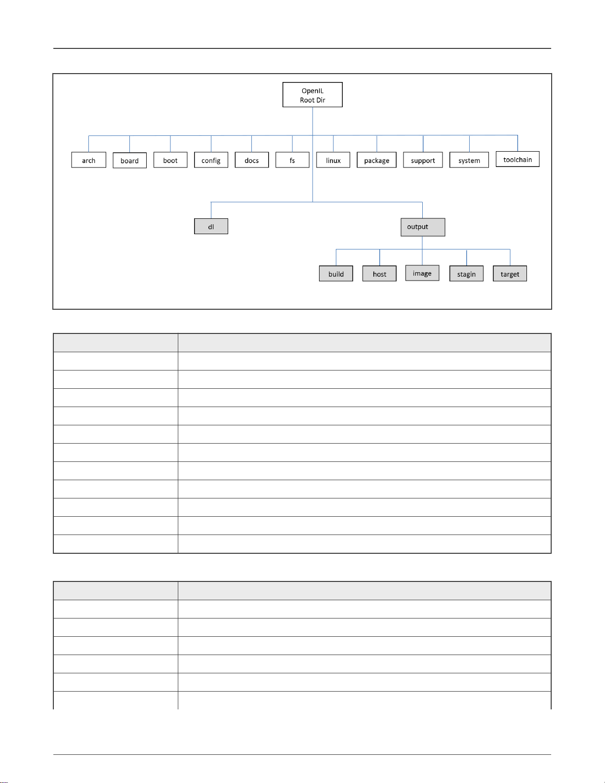
1.3.1 OpenIL Organization
OpenIL follows the Buildroot directory structure depicted in the following figure. The second and third levels of the directory are
generated during compilation.
Open Industrial User Guide, Rev. 1.10, 12/2020
User's Guide 10 / 263
Page 11
NXP Semiconductors
Figure 1. OpenIL structure
Table 2. Source directories
Introduction
Directory name Description
arch Files defining the architecture variants (processor type, ABI, floating point, etc.)
toolchain Packages for generating or using tool-chains
system Contains the rootfs skeleton and options for system-wide features
linux The linux kernel package.
package All the user space packages (1800+)
fs Logic to generate file system images in various formats
boot Boot-loader packages
configs Default configuration files for various platforms
board Board-specific files (kernel configurations, patches, image flashing scripts, etc.)
support Miscellaneous utilities (kconfig code, libtool patches, download helpers, and more)
docs Documentation
Table 3. Build directories
Directory name Description
dl Path where all the source tarballs are downloaded
output Global output directory
output/build Path where all source tarballs are extracted and the build of each package takes place.
output/host Contains both the tools built for the host and the sysroot of the toolchain
output/staging A symbolic link to the sysroot, that is, to host/<tuple>/sysroot/ for convenience
output/target The target Linux root filesystem, used to generate the final root filesystem images
Table continues on the next page...
Open Industrial User Guide, Rev. 1.10, 12/2020
User's Guide 11 / 263
Page 12

NXP Semiconductors
Table 3. Build directories (continued)
Directory name Description
output/images Contains all the final images: kernel, bootloader, root file system, and so on
1.4 Supported NXP platforms and configurations
The following table lists the NXP platforms and configurations supported by OpenIL.
Table 4. Supported NXP platforms
Platform Architecture Configuration file in OpenIL Boot
LS1021ATSN (default) ARM v7 configs/nxp_ls1021atsn_defconfig SD
LS1021ATSN (OP-TEE-SB) ARM v7 configs/nxp_ls1021atsn_optee-sb_defconfig SD
LS1021ATSN (Ubuntu) ARM v7 configs/nxp_ls1021atsn_ubuntu_defconfig SD
LS1021AIOT (default) ARM v7 configs/nxp_ls1021aiot_defconfig SD
LS1021AIOT (OP-TEE) ARM v7 configs/nxp_ls1021aiot_optee_defconfig SD
LS1021AIOT (Baremetal) ARM v7 configs/nxp_ls1021aiot_baremetal_defconfig SD
Introduction
LS1021AIOT (Ubuntu) ARM v7 configs/nxp_ls1021aiot_ubuntu_defconfig SD
LS1021ATWR (default, QSPI) ARM v7 configs/nxp_ls1021atwr_defconfig SD
LS1021ATWR (IFC) ARM v7 configs/nxp_ls1021atwr_sdboot_ifc_defconfig SD
LS1043ARDB (64bit, default) ARM v8 configs/nxp_ls1043ardb-64b_defconfig SD
LS1043ARDB (Baremetal) ARM v8 configs/nxp_ls1043ardb_baremetal-64b_defconfig SD
LS1043ARDB (Ubuntu) ARM v8 configs/nxp_ls1043ardb-64b_ubuntu_defconfig SD
LS1046ARDB (64bit, default) ARM v8 configs/nxp_ls1046ardb-64b_defconfig SD
LS1046ARDB (EMMC) ARM v8 configs/nxp_ls1046ardb-64b-emmcboot_defconfig EMMC
LS1046ARDB (QSPI) ARM v8 configs/nxp_ls1046ardb-64b_qspi_defconfig QSPI
LS1046ARDB (QSPI-SB) ARM v8 configs/nxp_ls1046ardb-64b_qspi-sb_defconfig QSPI
LS1046ARDB (Baremetal) ARM v8 configs/nxp_ls1046ardb_baremetal-64b_defconfig SD
LS1046ARDB (Ubuntu) ARM v8 configs/nxp_ls1046ardb-64b_ubuntu_defconfig SD
LS1046AFRWY (64bit, default) ARM v8 configs/nxp_ls1046afrwy-64b_defconfig SD
LS1046AFRWY (QSPI) ARM v8 configs/nxp_ls1046afrwy-64b_qspi_defconfig QSPI
LS1046AFRWY (Ubuntu) ARM v8 configs/nxp_ls1046afrwy-64b_ubuntu_defconfig SD
LS1012ARDB (64bit) ARM v8 configs/nxp_ls1012ardb-64b_defconfig QSPI
i.MX6Q SabreSD (default) ARM v7 configs/imx6q-sabresd_defconfig SD
i.MX6Q SabreSD (Baremetal) ARM v7 configs/imx6q-sabresd_baremetal_defconfig SD
i.MX6Q SabreSD (Ubuntu) ARM v7 configs/imx6q-sabresd_ubuntu_defconfig SD
i.MX8MM EVK (64bit default) ARM v8 configs/imx8mmevk_defconfig SD
Table continues on the next page...
Open Industrial User Guide, Rev. 1.10, 12/2020
User's Guide 12 / 263
Page 13

NXP Semiconductors
Table 4. Supported NXP platforms (continued)
Platform Architecture Configuration file in OpenIL Boot
Introduction
i.MX8MM EVK (64bit default)
ARM v8 configs/imx8mmevk_revb_defconfig SD
i.MX8MM EVK (Baremetal) ARM v8 configs/imx8mmevk_baremetal_defconfig SD
i.MX8MM EVK (Baremetal) ARM v8 configs/imx8mmevk_revb_baremetal_defconfig SD
i.MX8MM EVK (Ubuntu)
i.MX8MM EVK (Ubuntu) ARM v8
ARM v8
configs/imx8mmevk_ubuntu_defconfig SD
configs/imx8mmevk_revb_ubuntu_defconfig SD
i.MX8MP EVK (64bit, default) ARM v8 configs/imx8mpevk_defconfig SD
i.MX8MP EVK (Ubuntu) ARM v8 configs/imx8mpevk_ubuntu_defconfig SD
LS1028ARDB (64bit, default) ARM v8 configs/nxp_ls1028ardb-64b_defconfig SD
LS1028ARDB (EMMC) ARM v8 configs/nxp_ls1028ardb-64b-emmc_defconfig EMMC
LS1028ARDB (XSPI) ARM v8 configs/nxp_ls1028ardb-64b-xspi_defconfig XSPI
LS1028ARDB (Baremetal) ARM v8 configs/nxp_ls1028ardb_baremetal-64b_defconfig SD
LS1028ARDB (Ubuntu) ARM v8 configs/nxp_ls1028ardb-64b_ubuntu_defconfig SD
LS1028ATSN(64bit, default) ARM v8 configs/fii_ls1028atsn-64b_defconfig SD
LS1028ATSN(Ubuntu) ARM v8 configs/fii_ls1028atsn-64b_ubuntu_defconfig SD
LX2160ARDB (64bit, default) ARM v8 configs/nxp_lx2160ardb-64b_defconfig SD
LX2160ARDB (XSPI) ARM v8 configs/nxp_lx2160ardb-64b-xspi_defconfig XSPI
LX2160ARDB (Baremetal) ARM v8 configs/nxp_lx2160ardb_baremetal-64b_defconfig SD
LX2160ARDB (Ubuntu) ARM v8 configs/nxp_lx2160ardb-64b_ubuntu_defconfig SD
LX2160A Rev2 (64bit, default) ARM v8 configs/nxp_lx2160ardb_rev2-64b_defconfig SD
LX2160A Rev2 (XSPI) ARM v8 configs/nxp_lx2160ardb_rev2-64b-xspi_defconfig XSPI
LX2160A Rev2 (Baremetal) ARM v8 configs/nxp_lx2160ardb_rev2_baremetal-64b_defconfig SD
LX2160A Rev2 (Ubuntu) ARM v8 configs/nxp_lx2160ardb_rev2-64b_ubuntu_defconfig SD
1.4.1 Default compilation settings for NXP platforms
The following table provides the default compilation settings for each OpenIL NXP platform.
Table 5. Default compilation settings
Platform Toolchain libc Init system Filesystem
LS1021ATSN gcc 9.2.0 glibc 2.31 BusyBox OpenIL default
LS1021ATSN (OP-TEE) gcc 9.20 glibc 2.31 BusyBox OpenIL default
LS1021ATSN (Ubuntu) gcc 7.5.0 glibc 2.25 Systemd ubuntu-base-18.04.5-arm
LS1021AIOT gcc 9.2.0 glibc 2.31 BusyBox OpenIL default
LS1021AIOT (OP-TEE) gcc 9.2.0 glibc 2.31 BusyBox OpenIL default
Table continues on the next page...
Open Industrial User Guide, Rev. 1.10, 12/2020
User's Guide 13 / 263
Page 14

NXP Semiconductors
Table 5. Default compilation settings (continued)
Platform Toolchain libc Init system Filesystem
LS1021AIOT (Ubuntu) gcc 7.5.0 glibc 2.25 Systemd ubuntu-base-18.04.5-arm
LS1021ATWR gcc 9.2.0 glibc 2.31 BusyBox OpenIL default
LS1043ARDB (64-bit) gcc 9.2.0 glibc 2.31 BusyBox OpenIL default
LS1043ARDB (Ubuntu) gcc 9.2.0 glibc 2.31 Systemd ubuntu-base-18.04.5-arm64
LS1046ARDB (64-bit) gcc 9.2.0 glibc 2.31 BusyBox OpenIL default
LS1046ARB (Ubuntu) gcc 9.2.0 glibc 2.31 Systemd ubuntu-base-18.04.5-arm64
LS1046AFRWY (64-bit) gcc 9.2.0 glibc 2.31 BusyBox OpenIL default
LS1046AFRWY (Ubuntu) gcc 9.2.0 glibc 2.31 Systemd ubuntu-base-18.04.5-arm64
LS1012ARDB (64-bit) gcc 9.2.0 glibc 2.31 BusyBox OpenIL default
i.MX6Q SabreSD gcc 9.2.0 glibc 2.31 BusyBox OpenIL default
i.MX6Q SabreSD (Ubuntu) gcc 7.5.0 glibc 2.25 Systemd ubuntu-base-18.04.5-arm
Introduction
i.MX8MM EVK (64bit) gcc 9.2.0
i.MX8MM EVK (Ubuntu)
gcc 9.2.0 glibc 2.31 Systemd ubuntu-base-18.04.5-arm64
glibc 2.31 BusyBox OpenIL default
i.MX8MP EVK (64bit) gcc 9.2.0 glibc 2.31 BusyBox OpenIL default
i.MX8MP EVK (Ubuntu) gcc 9.2.0 glibc 2.31 Systemd ubuntu-base-18.04.5-arm64
LS1028ARDB (64-bit) gcc 9.2.0 glibc 2.31 BusyBox OpenIL default
LS1028ARDB (Ubuntu) gcc 9.2.0 glibc 2.31 Systemd ubuntu-base-18.04.5-arm64
LS1028ATSN (64-bit) gcc 9.2.0 glibc 2.31 BusyBox OpenIL default
LS1028ATSN (Ubuntu) gcc 9.2.0 glibc 2.31 Systemd ubuntu-base-18.04.5-arm64
LX2160ARDB (64-bit) gcc 9.2.0 glibc 2.31 BusyBox OpenIL default
LX2160ARDB (Ubuntu) gcc 9.2.0 glibc 2.31 Systemd ubuntu-base-18.04.5-arm64
LX2160A Rev2 RDB (64bit) gcc 9.2.0 glibc 2.31 BusyBox OpenIL-default
LX2160A Rev2 RDB (Ubuntu) gcc 9.2.0 glibc 2.31 Systemd ubuntu-base-18.04.5-arm64
Open Industrial User Guide, Rev. 1.10, 12/2020
User's Guide 14 / 263
Page 15

NXP Semiconductors
Chapter 2
Getting started
After reading this section, user should be able to get the OpenIL source code, build and program the NXP platform images, and
run the OpenIL system on the supported NXP platforms.
2.1 Getting OpenIL
OpenIL releases are available every a few months. The Release Number follows the format 'YYYYMM', for example, 201708.
Release tarballs are available at: https://github.com/openil/openil.
To follow development, make a clone of the Git repository. Use the below command:
$ git clone https://github.com/openil/openil.git
$ cd openil
# checkout to the 2020.12 v1.10 release
$ git checkout OpenIL-v1.10-202012 -b OpenIL-v1.10-202012
2.2 OpenIL quick start
The steps below help the user to build the NXP platform images with OpenIL quickly. Ensure to follow the important notes provided
in the following section.
2.2.1 Host system requirements
OpenIL is designed to build in Linux systems. The following host environments have been verified to build the OpenIL.
• Ubuntu 20.04 (Recommended)
• Ubuntu 18.04
• Ubuntu 16.04
While OpenIL itself builds most host packages it needs for the compilation, certain standard Linux utilities are expected to be
already installed on the host system. The following tables provide an overview of the mandatory and optional packages.
User also can run following script to make sure all packages required have been installed into HOST machine.
$ cd openil
# Run below command to check and install these packages required automatically.
$ ./env_setup.sh
NOTE
Package names listed in the following tables might vary between distributions.
NOTE
When Building i.MX8MMEVK and i.MX8MPEVK images, the Host machine requres Ubuntu-20.04 or later because
gstreamer1.0-1.16.1 needs GLIB 2.29 or later (Ubuntu-18.04 is 2.27). If the host machine is not Ubuntu-20.04,
please refer to chapter 25 "Camera" to disable gstreamer .
Table 6. Host system mandatory packages
Mandatory packages Remarks
which
Table continues on the next page...
Open Industrial User Guide, Rev. 1.10, 12/2020
User's Guide 15 / 263
Page 16

NXP Semiconductors
Table 6. Host system mandatory packages (continued)
Mandatory packages Remarks
sed
make Version 3.81 or later
binutils
build-essential Only for Debian based systems
gcc Version 2.95 or later
g++ Version 2.95 or later
bash
patch
gzip
bzip2
perl Version 5.8.7 or later
tar
Getting started
cpio
python Version 2.6 or later
unzip
rsync
file Must be in /usr/bin/file
bc
wget
autoconf, dh-autoreconf
openssl, libssl-dev
libmagickwand-dev
(Debian, Ubuntu)
imageMagick-devel (CentOS)
autogen autoconf libtool
pkg-config
python3-pyelftools
python-pyelftools
python3-pycryptodome
python-pycryptodome
binfmt-support used when building ubuntu-rootfs
qemu-system-common used when building ubuntu-rootfs
qemu-user-static used when building ubuntu-rootfs
Table continues on the next page...
Open Industrial User Guide, Rev. 1.10, 12/2020
User's Guide 16 / 263
Page 17

NXP Semiconductors
Table 6. Host system mandatory packages (continued)
Mandatory packages Remarks
debootstrap used when building ubuntu-rootfs
Table 7. Host system optional packages
Optional packages Remarks
ncurses5 To use the menuconfig interface
qt4 To use the xconfig interface
glib2, gtk2 and glade2 To use the gconfig interface
Getting started
bazaar
cvs
git
Source fetching tools.
If user enable packages using any of these methods, user need to install the corresponding tool
on the host system
mercurial
scp
javac compiler Java-related packages, if the Java Classpath needs to be built for the target system
jar tool
asciidoc Documentation generation tools
w3m
python with the
argparse module
dblatex
graphviz To use graph-depends and <pkg>-graph-depends
python-matplotlib To use graph-build
2.2.2 Creating RAMDISK file system
OpenIL support to generate RAMDISK file system.
• Create Ramdisk root filesystem by using the make menuconfig command.
Filesystem images --->
[*] cpio the root filesystem (for use as an initial RAM filesystem)
[*] Create U-Boot image of the root filesystem
This configuration will generate Ramdisk root filesystem based on CPIO, some files created: rootfs.cpio.uboot,
rootfs.cpio.gz, rootfs.cpio.
2.2.3 Resizing second partition
Resizing the second partition, which is root filesystem.
Open Industrial User Guide, Rev. 1.10, 12/2020
User's Guide 17 / 263
Page 18

NXP Semiconductors
Getting started
• Specify partition size of the storage for the filesystem by using the make menuconfig command.
System configuration --->
(3G) Partition size of the storage for the rootfs
[*] Install rootfs_resize service
This configuration specifies the size of the storage device partition for the building rootfs and currently used by NXP platforms
and SD card device. The default size is 3GB, user can set the size of the partition with 512M, 2G or other values, the target
system can get the specific size of partition space for the using filesystem.
• Another way to modify the space size of second partition: using tool "fdisk" to resize the partition on HOST machine, below
are the example steps.
# First flash sdcard.img to SD card on host machine wiht dd command
~$ sudo dd if=./sdcard.img of=/dev/sdc
# Then list the partitions
~$ sudo fdisk -l /dev/sdc
Disk /dev/sdc: 7.4 GiB, 7948206080 bytes, 15523840 sectors
Units: sectors of 1 * 512 = 512 bytes
Sector size (logical/physical): 512 bytes / 512 bytes
I/O size (minimum/optimal): 512 bytes / 512 bytes
Disklabel type: dos
Disk identifier: 0x00000000
Device Boot Start End Sectors Size Id Type
/dev/sdc1 * 131072 655359 524288 256M c W95 FAT32 (LBA)
/dev/sdc2 655360 1703935 1048576 512M 83 Linux
# Notice: we need this start sectors "655360" of second partition when create new partition.#
# Then, Re-create the second partition and expand to full SD capability
~$ sudo fdisk /dev/sdc
Welcome to fdisk (util-linux 2.31.1).
Changes will remain in memory only, until you decide to write them.
Be careful before using the write command.
Command (m for help): d
Partition number (1,2, default 2):
Partition 2 has been deleted.
Command (m for help): n
Partition type
p primary (1 primary, 0 extended, 3 free)
e extended (container for logical partitions)
Select (default p):
Using default response p.
Partition number (2-4, default 2):
First sector (2048-15523839, default 2048): 655360
Last sector, +sectors or +size{K,M,G,T,P} (655360-15523839, default 15523839):
Created a new partition 2 of type 'Linux' and of size 7.1 GiB.
Partition #2 contains a ext4 signature.
Do you want to remove the signature? [Y]es/[N]o: n
Command (m for help): w
Open Industrial User Guide, Rev. 1.10, 12/2020
User's Guide 18 / 263
Page 19

NXP Semiconductors
The partition table has been altered.
Calling ioctl() to re-read partition table.
Syncing disks.
# Finally, check the second partiton and resize to full SD capability
~$ sudo fsck.ext4 /dev/sdc2
e2fsck 1.44.1 (24-Mar-2018)
/dev/sdc2: clean, 3493/32768 files, 26617/131072 blocks
~$ sudo resize2fs /dev/sdc2
resize2fs 1.44.1 (24-Mar-2018)
Resizing the filesystem on /dev/sdc2 to 1858560 (4k) blocks.
The filesystem on /dev/sdc2 is now 1858560 (4k) blocks long.
~$ sudo fdisk -l /dev/sdc
Disk /dev/sdc: 7.4 GiB, 7948206080 bytes, 15523840 sectors
Units: sectors of 1 * 512 = 512 bytes
Sector size (logical/physical): 512 bytes / 512 bytes
I/O size (minimum/optimal): 512 bytes / 512 bytes
Disklabel type: dos
Disk identifier: 0x00000000
Device Boot Start End Sectors Size Id Type
/dev/sdc1 * 131072 655359 524288 256M c W95 FAT32 (LBA)
/dev/sdc2 655360 15523839 14868480 7.1G 83 Linux
Getting started
2.2.4 Customing Ubuntu file system
OpenIL supports custom Ubuntu as the target root file system. This section describes the steps for customing the Ubuntu root
file system.
Users can download OpenIL and build the target system with an Ubuntu file system. The specific filesystem can be set
conveniently by using the make menuconfig command as shown below.
NOTE
The "sudo" permission is required when building ubuntu root file system.
System configuration --->
Root FS skeleton (custom target skeleton) --->
Custom skeleton via network --->
Currently, there are ten NXP platforms that can support Ubuntu file system:
• configs/nxp_ls1043ardb-64b_ubuntu_defconfig
• configs/nxp_ls1043ardb-64b_ubuntu_full_defconfig
• configs/nxp_ls1046ardb-64b_ubuntu_defconfig
• configs/nxp_ls1046ardb-64b_ubuntu_full_defconfig
• configs/nxp_ls1046afrwy-64b_ubuntu_defconfig
• configs/nxp_ls1046afrwy-64b_ubuntu_full_defconfig
• configs/fii_ls1028atsn-64b_ubuntu_defconfig
• configs/fii_ls1028atsn-64b_ubuntu_full_defconfig
• configs/nxp_ls1028ardb-64b_ubuntu_defconfig
• configs/nxp_ls1028ardb-64b_ubuntu_full_defconfig
• configs/nxp_ls1021aiot_ubuntu_defconfig
• configs/nxp_ls1021aiot_ubuntu_full_defconfig
Open Industrial User Guide, Rev. 1.10, 12/2020
User's Guide 19 / 263
Page 20

NXP Semiconductors
• configs/nxp_ls1021atsn_ubuntu_defconfig
• configs/nxp_ls1021atsn_ubuntu_full_defconfig
• configs/imx6q-sabresd_ubuntu_defconfig
• configs/imx6q-sabresd_ubuntu_full_defconfig
• configs/nxp_lx2160ardb-64b_ubuntu_defconfig
• configs/nxp_lx2160ardb-64b_ubuntu_full_defconfig
• configs/nxp_lx2160ardb_rev2-64b_ubuntu_defconfig
• configs/nxp_lx2160ardb_rev2-64b_ubuntu_full_defconfig
• configs/imx8mmevk_revb_ubuntu_defconfig
• configs/imx8mmevk_ubuntu_defconfig
• configs/imx8mpevk_ubuntu_defconfig
NOTE
In the package list specified above:
• **_ubuntu_default: supports basic packages to boot the system.
• **_ubuntu_full_default: supports all packages in **_ubuntu_default and other necessary
packages required by all features.
Getting started
2.2.5 Building the images
For the NXP platforms supported by OpenIL, the default configuration files can be found in the configs directory. The following
table describes the default configuation files for the NXP-supported OpenIL platforms.
Table 8. Default configuration
Platform Configuration file in OpenIL
i.MX6Q SabreSD configs/imx6q-sabresd_defconfig
i.MX6Q SabreSD (Baremtal) configs/imx6q-sabresd_baremetal_defconfig
i.MX6Q SabreSD (Ubuntu) configs/imx6q-sabresd_ubuntu_defconfig
i.MX6Q SabreSD (Full ubuntu) configs/imx6q-sabresd_ubuntu_full_defconfig
i.MX8MM EVK (64bit) configs/imx8mmevk_revb_defconfig
i.MX8MM EVK (64bit)
i.MX8MM EVK (Baremetal)
i.MX8MM EVK (Baremetal)
i.MX8MM EVK (
Ubuntu)
configs/imx8mmevk_defconfig
configs/imx8mmevk_baremetal_defconfig
configs/imx8mmevk_revb_baremetal_defconfig
configs/imx8mmevk_ubuntu_defconfig
i.MX8MM EVK (Ubuntu)
configs/imx8mmevk_revb_ubuntu_defconfig
i.MX8MP EVK (64bit) configs/imx8mpevk_defconfig
i.MX8MP EVK (Ubuntu) configs/imx8mpevk_ubuntu_defconfig
Table continues on the next page...
Open Industrial User Guide, Rev. 1.10, 12/2020
User's Guide 20 / 263
Page 21

NXP Semiconductors
Table 8. Default configuration (continued)
Platform Configuration file in OpenIL
LS1012ARDB (64bit) configs/nxp_ls1012ardb-64b_defconfig
LS1021AIOT configs/nxp_ls1021aiot_defconfig
LS1021AIOT (OP-TEE) configs/nxp_ls1021aiot_optee_defconfig
LS1021AIOT (Baremetal) configs/nxp_ls1021aiot_baremetal_defconfig
LS1021AIOT (Ubuntu) configs/nxp_ls1021aiot_ubuntu_defconfig
LS1021AIOT (Full ubuntu) configs/nxp_ls1021aiot_ubuntu_full_defconfig
LS1021ATSN configs/nxp_ls1021atsn_defconfig
LS1021ATSN (OP-TEE-SB) configs/nxp_ls1021atsn_optee-sb_defconfig
LS1021ATSN (Ubuntu) configs/nxp_ls1021atsn_ubuntu_defconfig
LS1021ATSN (Full ubuntu) configs/nxp_ls1021atsn_ubuntu_full_defconfig
LS1021ATWR (QSPI) configs/nxp_ls1021atwr_defconfig
LS1021ATWR (IFC) configs/nxp_ls1021atwr_sdboot_ifc_defconfig
Getting started
LS1028ARDB (EMMC) configs/nxp_ls1028ardb-64b-emmc_defconfig
LS1028ARDB (XSPI) configs/nxp_ls1028ardb-64b-xspi_defconfig
LS1028ARDB (Baremetal) configs/nxp_ls1028ardb_baremetal-64b_defconfig
LS1028ARDB (64bit) configs/nxp_ls1028ardb-64b_defconfig
LS1028ARDB (Ubuntu) configs/nxp_ls1028ardb-64b_ubuntu_defconfig
LS1028ARDB (Full ubuntu) configs/nxp_ls1028ardb-64b_ubuntu_full_defconfig
LS1028ATSN (64bit) configs/fii_ls1028atsn-64b_defconfig
LS1028ATSN (Ubuntu) configs/fii_ls1028atsn-64b_ubuntu_defconfig
LS1028ATSN (Full ubuntu) configs/fii_ls1028atsn-64b_ubuntu_full_defconfig
LS1043ARDB (64bit) configs/nxp_ls1043ardb-64b_defconfig
LS1043ARDB (Baremetal) configs/nxp_ls1043ardb_baremetal-64b_defconfig
LS1043ARDB (Ubuntu) configs/nxp_ls1043ardb-64b_ubuntu_defconfig
LS1043ARDB (Full ubuntu) configs/nxp_ls1043ardb-64b_ubuntu_full_defconfig
LS1046ARDB (64-bit) configs/nxp_ls1046ardb-64b_defconfig
LS1046ARDB (EMMC) configs/nxp_ls1046ardb-64b-emmcboot_defconfig
LS1046ARDB (QSPI) configs/nxp_ls1046ardb-64b_qspi_defconfig
LS1046ARDB (QSPI-SB) configs/nxp_ls1046ardb-64b_qspi-sb_defconfig
LS1046ARDB (QSPI4EMMC) configs/nxp_ls1046ardb-64b-emmc_qspiboot_defconfig
LS1046ARDB (Baremetal) configs/nxp_ls1046ardb_baremetal-64b_defconfig
LS1046ARDB (Ubuntu) configs/nxp_ls1046ardb-64b_ubuntu_defconfig
Table continues on the next page...
Open Industrial User Guide, Rev. 1.10, 12/2020
User's Guide 21 / 263
Page 22

NXP Semiconductors
Table 8. Default configuration (continued)
Platform Configuration file in OpenIL
LS1046ARDB (Full ubuntu) configs/nxp_ls1046ardb-64b_ubuntu_full_defconfig
LS1046AFRWY (64bit) configs/nxp_ls1046afrwy-64b_defconfig
LS1046AFRWY (QSPI) configs/nxp_ls1046afrwy-64b_qspi_defconfig
LS1046AFRWY (Ubuntu) configs/nxp_ls1046afrwy-64b_ubuntu_defconfig
LS1046AFRWY (Full ubuntu) configs/nxp_ls1046afrwy-64b_ubuntu_full_defconfig
LX2160ARDB (64bit) configs/nxp_lx2160ardb-64b_defconfig
LX2160ARDB (XSPI) configs/nxp_lx2160ardb-64b-xspi_defconfig
LX2160ARDB (Baremetal) configs/nxp_lx2160ardb_baremetal-64b_defconfig
LX2160ARDB (Ubuntu) configs/nxp_lx2160ardb-64b_ubuntu_defconfig
LX2160ARDB (Full ubuntu) configs/nxp_lx2160ardb-64b_ubuntu_full_defconfig
LX2160A Rev2 RDB (64bit) configs/nxp_lx2160ardb_rev2-64b_defconfig
LX2160A Rev2 RDB (XSPI) configs/nxp_lx2160ardb_rev2-64b-xspi_defconfig
Getting started
LX2160A Rev2 RDB (Baremetal) configs/nxp_lx2160ardb_rev2_baremetal-64b_defconfig
LX2160A Rev2 RDB (Ubuntu) configs/nxp_lx2160ardb_rev2-64b_ubuntu_defconfig
LX2160A Rev2 RDB (Full ubuntu) configs/nxp_lx2160ardb_rev2-64b_ubuntu_full_defconfig
The “configs/nxp_xxxx_defconfig” files listed in the preceding table include all the necessary U-Boot, kernel
configurations, and application packages for the filesystem. Based on the files without any changes, user can build a complete
Linux environment for the target platforms.
To build the images for an NXP platform (for example, LS1046ARDB), run the following commands:
$ cd openil
$ make nxp_ls1046ardb-64b_defconfig
$ make
# or make with a log
$ make 2>&1 | tee build.log
NOTE
The make clean command should be implemented before any other new compilation.
The make command generally performs the following steps:
• Downloads source files (as required and at the first instance);
• Configures, builds, and installs the cross-compilation toolchain;
• Configures, builds, and installs selected target packages;
• Builds a kernel image, if selected;
• Builds a bootloader image, if selected;
• Creates the BL2, BL31, BL33 binary from ATF;
• Creates a root filesystem in selected formats.
• Generates the Image file for booting;
Open Industrial User Guide, Rev. 1.10, 12/2020
User's Guide 22 / 263
Page 23

NXP Semiconductors
After the correct compilation, all the images for the platform can be found at output/images.
images/
├── bl2_sd.pbl --- BL2 + RCW
├── fip.bin --- BL31 + BL33 (uboot)
├── rcw_1800_sdboot.bin --- RCW binary
├── boot.vfat
├── fmucode.bin
├── fsl-ls1046a-rdb-sdk.dtb --- dtb file for ls1046ardb
├── rootfs.ext2
├── rootfs.ext4
├── rootfs.tar
├── sdcard.img --- entire image can be programmed into the SD
├── uboot-env.bin
├── u-boot-dtb.bin --- uboot image for ls1046ardb
└── Image --- kernel image for ls1046ardb
NOTE
The image file name used for each configuration are as described below:
• xspi.cpio.img: the image file used for FlexNor flash boot, built by the *xspi_defconfig file.
• sdcard.img: the image file used for SD or eMMC boot, built by default and *emmc_defconfig file.
Getting started
• qspi.cpio.img: the image file used for QSPI flash boot, built by *qspi_defconfig file.
2.2.6 Troubleshooting
• Users can login all platforms through SSH. However, for LS1028ARDB, i.MX8MMEVK and i.MX8MPEVK, Linux-PAM is
enabled, which is required by weston. Hence, if users don't want to follow Linux-PAM policy to login through SSH, the below
steps are necessary:
1> Open file /etc/ssh/sshd_config and comment out the below line:
# UsePAM yes
2> Then, restart SSHD using the command:
$ /etc/init.d/S50sshd restart
• All configurations are built by the nomal user. But, "sudo" permission is required when building ubuntu root file system on
HOST machine. User can enter below line to file "/etc/sudoers" to avoid entering sudo password during building ("username"
should be changed to the true user name):
username ALL=(ALL:ALL) NOPASSWD:ALL
• The PERL_MM_OPT issue: Users might encounter an error message for the PERL_MM_OPT parameter when using the make
command in some host Linux environments as shown below:
You have PERL_MM_OPT defined because Perl local::lib is installed on your system.
Please unset this variable before starting Buildroot, otherwise the compilation of Perl
related packages will fail.
make[1]: *** [core-dependencies] Error 1
make: *** [_all] Error 2
To resolve this issue, just unset the PERL_MM_OPT parameter.
$ unset PERL_MM_OPT
Open Industrial User Guide, Rev. 1.10, 12/2020
User's Guide 23 / 263
Page 24

NXP Semiconductors
2.3 Booting the board
Getting started
Before proceeding further with the instructions in this section, refer to the
Getting Started Guide
of the respective board for detailed
instructions regarding board boot-up. See Reference documentation.
NOTE
• Before booting up the board, user need to install mbed Windows serial port driver in order to obtain the board
console. This is a one time activity. Please ignore this step if user have already installed the mbed driver on
user system (PC or laptop). User can download the mbed Windows serial port driver from the link below:
https://developer.mbed.org/handbook/Windows-serial-configuration.
• Download and install Tera Term on the host computer from the Internet. After installation, a shortcut to the tool
is created on the desktop of the host computer.
• If user is using a Windows 10 machine as a host computer and encountering a serial port unstable issue, then,
disable the
Volume Storage
service of the Windows machine.
All the NXP platforms can be booted up from the SD card or QSPI flash. After the compilation for one platform, the image files
(sdcard.img or qspi.img) are generated in the folder output/images. The following table describes the software settings to be
used while booting up the NXP platforms with the images built from OpenIL.
Table 9. Switch settings for the NXP boards
Platform Boot mode Image name Board SWITCH Setting (ON = 1)
i.MX6Q SabreSD SD card sdcard.img SW6 = 0b’01000010
i.MX8MMEVK SD card Sdcard.img
i.MX8MMEVK-RevB SD card Sdcard.img
SW1101 = 0b'01000110, SW1102 = 0b'00110100
SW1101 = 0b'0110110010, SW1102 = 0b'0001101000
i.MX8MP EVK SD card sdcard.img SW4[1-4] = 0b'0011
LS1012ARDB QSPI qspi.cpio.im
g
SW1 = 0b'10100110
SW2 = 0b'00000000
LS1021AIOT SD card sdcard.img SW2[1] = 0b’0
LS1021ATSN SD card sdcard.img SW2 = 0b’111111
LS1021ATWR SD card sdcard.img QSPI enabled: SW2[1-8] = 0b'00101000, SW3[1-8] = 0b'01100001
IFC enabled: SW2[1-8] = 0b'00100000, SW3[1-8] = 0b'01100001
LS1028ARDB SD card sdcard.img SW2[1-8] = 0b’10001000
LS1043ARDB SD card sdcard.img SW4[1-8] +SW5[1] = 0b'00100000_0
LS1046ARDB SD card sdcard.img SW5[1-8] +SW4[1] = 0b'00100000_0
LS1046AFRWY SD card sdcard.img SW1[1-9] = 0b'0_01000000
LX2160ARDB/Rev2 SD card sdcard.img SW1[1-4] = 0b’1000
The flash image (
sdcard.img or qspi.img
) includes all the information: RCW, DTB, U-Boot, kernel, rootfs, and
necessary applications.
NOTE
Make sure the board is set to boot up from SD card or QSPI using software configuration. Refer to the preceding
table for the switch settings for the respective platform.
.
Open Industrial User Guide, Rev. 1.10, 12/2020
User's Guide 24 / 263
Page 25

NXP Semiconductors
Getting started
2.3.1 SD card bootup
For platforms that can be booted up from an SD card, following are the steps to program the sdcard.img.into an SD card:
1. Insert one SD card (at least 4G size) into any Linux host machine.
2. Run the below commands:
$ sudo dd if=./sdcard.img of=/dev/sdx
# or in some other host machine:
$ sudo dd if=./sdcard.img of=/dev/mmcblkx
# find the right SD Card device name in user host machine and replace the “sdx” or “mmcblkx”.
3. Now, insert the SD card into the target board (switch the board boot from SD card first) and power on.
2.3.2 QSPI/FlexSPI bootup
For platforms that can be booted up from QSPI (for example, LS1012ARDB), following are the steps to program the qspi.img into
QSPI flash.
Set the board boot from QSPI, then power on, and enter the U-Boot command environment.
FlexSPI (XSPI, image name is xspi.cpio.img) boot has the same commands to make the flash.
# In order to void damage the default bank which will cause the board can NOT bootup, we need to
write the image to altbank for ls1012ardb
# First, select the altbank with below command
=>i2c mw 0x24 0x7 0xfc; i2c mw 0x24 0x3 0xf5
# Then, download the image qspi.cpio.img
=>tftp 0x80000000 qspi.cpio.img
# Last, erase the flash and write the image to flash
=>sf probe 0:0
=>sf erase 0x0 +$filesize
=>sf write 0x80000000 0x0 $filesize
=>reset
2.3.3 eMMC bootup
For platforms that can be booted up from eMMC (for example, ls1028ardb, ls1046ardb), use the following steps to program the
sdcard image into eMMC:
LS1028ARDB eMMC bootup
1. Bootup the ls1028ardb into U-Bootprompt with XSPI or SD boot.
2. Download the image from server.
eMMC boot image is built with nxp_ls1028ardb-64b-emmc_defconfig.
Make sure that the network in U-Boot can access the TFTP server and the eMMC bootup image is ready in this server using
the command:
> tftpboot 0xa0000000 sdcard.img
3. Select eMMC as shown in the steps below:
=> mmc dev 1
=> mmcinfo
Device: FSL_SDHC
Manufacturer ID: 13
OEM: 14e
Open Industrial User Guide, Rev. 1.10, 12/2020
User's Guide 25 / 263
Page 26

NXP Semiconductors
Name: Q2J55
Bus Speed: 52000000
Mode: MMC High Speed (52MHz)
Rd Block Len: 512
MMC version 5.0
High Capacity: Yes
Capacity: 7.1 GiB
Bus Width: 4-bit
Erase Group Size: 512 KiB
HC WP Group Size: 8 MiB
User Capacity: 7.1 GiB WRREL
Boot Capacity: 2 MiB ENH
RPMB Capacity: 4 MiB ENH
4. Flash sdcard.img to eMMC:
First, erase eMMC, the block number is calculated by image-bytes/block-size (usually, the block size is 512).
For example, image bytes is 725191680, the block number is: 725191680 / 512 = 0x159CC6.
In the below example, the image size is assumed to be 725191680 and block number is 0x159CC6, hence parameter
greater than 0x159CC6 can be used, for example 0x160000. Users should change this parameter according to the true size
of the sdcard.img.
Getting started
=> mmc erase 0 0x160000
-> mmc write 0xa0000000 0 0x160000
5. Reset the board to eMMC boot:
=> qixis_reset emmc
Or, power off the ls1028ardb board, change the switch setting SW2[1-4] = 0b'1001, then power on ls1028ardb, the board can be
booted up from eMMC directly.
LS1046ARDB eMMC bootup
1. Build two images with nxp_ls1046ardb-64b-emmc_qspiboot_defconfig and nxp_ls1046ardb-64b-emmcboot_defconfig:
• qspi.cpio.img: built with nxp_ls1046ardb-64b-emmc_qspiboot_defconfig
• sdcard.img: built with nxp_ls1046ardb-64b-emmcboot_defconfig
2. Bootup the ls1046ardb board to uboot prompt with QSPI or SD boot Make sure the U-Boot network can access TFTP server
and these two images are ready in this server.
3. Flash qspi.cpio.img to QSPI to enable eMMC:
=> tftpboot 0xa0000000 qspi.cpio.img
=> sf probe 0:0
=> sf erase 0x0 +$filesize
=> sf write 0xa0000000 0x0 $filesize
4. Remove SD card from SD slot, and reset the board with qspi boot.
=> cpld reset qspi
5. Now the eMMC can be accessed as shown in the console log below:
=> mmcinfo
Device: FSL_SDHC
Manufacturer ID: fe
OEM: 14e
Open Industrial User Guide, Rev. 1.10, 12/2020
User's Guide 26 / 263
Page 27

NXP Semiconductors
Name: P1XXX
Bus Speed: 52000000
Mode : MMC High Speed (52MHz)
Rd Block Len: 512
MMC version 4.5
High Capacity: Yes
Capacity: 3.6 GiB
Bus Width: 4-bit
Erase Group Size: 512 KiB
HC WP Group Size: 4 MiB
User Capacity: 3.6 GiB
Boot Capacity: 2 MiB ENH
RPMB Capacity: 128 KiB ENH
6. Download eMMC bootup image:
=> tftpboot 0xa0000000 sdcard.img
7. Flash this image to eMMC
First, erase eMMC, the block number is calculated by image-bytes/block-size (usually, the block size is 512).
For example, if image bytes is 738197504, the block number is: 738197504 / 512 = 0x160000.
The below steps assume that for the image size of 738197504 and the block number 0x160000, the parameter greater than
0x160000 can be used, for example 0x170000.
Getting started
NOTE
Users should change this parameter according to the actual size of the sdcard image.
=> mmc erase 0 0x170000
-> mmc write 0xa0000000 0 0x170000
8. Reset the board to use eMMC boot:
=> cpld reset sd
Or, power off the ls1046ardb board, set the switch to SD boot, and power on the board.
NOTE
Make sure there is not SD card in the SD card slot if the user wants to perform eMMC boot.
2.3.4 Starting up the board
After programming the sdcard or qspi image, startup the board. Users should see the following information on the console.
Open Industrial User Guide, Rev. 1.10, 12/2020
User's Guide 27 / 263
Page 28
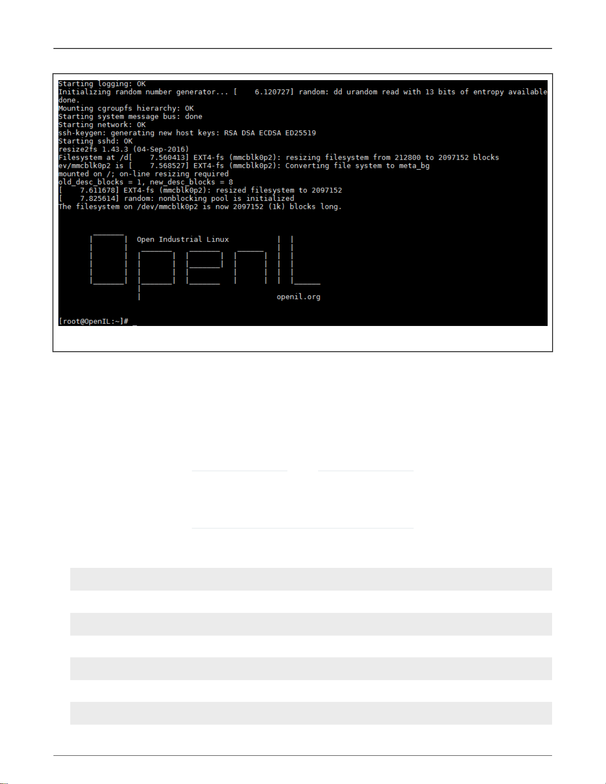
NXP Semiconductors
Getting started
Figure 2. OpenIL system startup
The system will be logged in automatically.
2.4 Basic OpenIL operations
This section describes the commands that can be used for performing basic OpenIL operations.
In OpenIL, all packages used are in directory ./package/, and the package name is the sub-directory name. Linux kernel and
uboot are also packages, the package name for Linux kernel is linux, and package name for u-boot is uboot. Packages "linux"
and "uboot" is not in directory "./package/", the path of package "linux" is "./linux", the path of package "uboot" is "./boot/uboot".
NOTE
Packages linux and uboot are not in directory ./package/.
• The path of package linux is ./linux, and
• The path of package uboot is ./boot/uboot.
Sample usages of the ‘make’ command:
• Displays all commands executed by using the make command:
$ make V=1 <target>
• Displays the list of boards with a defconfig:
$ make list-defconfigs
• Displays all available targets:
$ make help
• Sets Linux configurations:
$ make linux-menuconfig
Open Industrial User Guide, Rev. 1.10, 12/2020
User's Guide 28 / 263
Page 29

NXP Semiconductors
Getting started
• Deletes all build products (including build directories, host, staging and target trees, images, and the toolchain):
$ make clean
• Resets OpenIL for a new target.
• Deletes all build products as well as the configuration (including dl directory):
$ make distclean
NOTE
Explicit cleaning is required when any of the architecture or toolchain configuration options are changed.
• Downloading, building, modifying, and rebuilding a package
Run the below command to build and install a particular package and its dependencies:
$ make <pkg>
For packages relying on the OpenIL infrastructure, there are numerous special make targets that can be called independently
such as the below command:
$ make <pkg>-<target>
The package build targets are listed in the following table.
Table 10. Package build targets
Package Target Description
<pkg> Builds and installs a package and all its dependencies
<pkg>-source Downloads only the source files for the package
<pkg>-extract Extracts package sources
<pkg>-patch Applies patches to the package
<pkg>-depends Builds package dependencies
<pkg>-configure Builds a package up to the configure step
<pkg>-build Builds a package up to the build step
<pkg>-show-depends Lists packages on which the package depends
<pkg>-show-rdepends Lists packages which have the package as a dependency
<pkg>-graph-depends Generates a graph of the package dependencies
<pkg>-graph-rdepends Generates a graph of the package's reverse dependencies
<pkg>-dirclean Removes the package's build directory
<pkg>-reconfigure Restarts the build from the configure step
<pkg>-rebuild Restarts the build from the build step
Thus, a package can be downloaded in the directory dl/, extracted to the directory output/build/<pkg>, and then built in
the directory output/build/<pkg>. User need to modify the code in the output/build/<pkg>, and then run the command,
$make <pkg>-rebuild to rebuild the package.
Open Industrial User Guide, Rev. 1.10, 12/2020
User's Guide 29 / 263
Page 30

NXP Semiconductors
Getting started
For more details about OpenIL operations, refer to the Buildroot document available at the URL: https://buildroot.org/downloads/
manual/manual.html#getting-buildroot.
2.4.1 Building Linux kernel
OpenIL is a tool for building the final flash/SD image, including Linux kernel.
If users want to build the Linux kernel separately, they can follow the below methods:
1. Build Linux kernel in OpenIL without code modified
This is the simple method to build the Linux kernel, using the following command:
# enter openil directory
$ cd openil
# make one default configuration file, for example nxp_ls1028ardb-64b_defconfig
$ make nxp_ls1028ardb-64b_defconfig
# build the Linux kernel image, which will be stored in directory output/images/
$ make linux
2. Build Linux kernel in OpenIL with code modified: If users want to modify the Linux code and build it, follow the below steps:
a. Clone the Linux repos from github.com/openil/linux
$ git clone https://github.com/openil/linux.git
b. Enter "linux" repos and checkout to current release tag or any tag user want, for example
OpenIL-v1.10-linux-202012
$ git checkout -b OpenIL-v1.10-linux-202012 OpenIL-v1.10-linux-202012
c. Modify the code and generate the patch following "git" usage.
d. Copy these patches just generated from "linux" directory to openil linux directory with 0001-xx, 0002-xx, ... order
e. Build the Linux image with command "make linux":
$ make linux
3. Build Linux kernel in separate directory with code modified:
There is another way to build the Linux image with code modified. The following steps explain how to do it (taking ls1028ardb
board as an example).
a. Setup cross-compile environment.
# downloading toolchain armv8-64bit (ls1028ardb is armv8 and 64bit)
$ wget https://developer.arm.com/-/media/Files/downloads/gnu-a/9.2-2019.12/binrel/gccarm-9.2-2019.12-x86_64-aarch64-none-linux-gnu.tar.xz
# extracting the toolchain tarball to /opt
$ tar xvf gcc-arm-9.2-2019.12-x86_64-aarch64-none-linux-gnu.tar.xz -C /opt/
# setting environment variables
$ export PATH=$PATH:/opt/gcc-arm-9.2-2019.12-x86_64-aarch64-none-linux-gnu/bin/
$ export ARCH=arm64
$ export CROSS_COMPILE=aarch64-none-linux-gnu-
b. Clone the Linux repos from github.com/openil/linux.
$ git clone https://github.com/openil/linux.git
Open Industrial User Guide, Rev. 1.10, 12/2020
User's Guide 30 / 263
Page 31

NXP Semiconductors
c. Enter "linux" repository and checkout to the current release tag or the desired tag, for example OpenIL-v1.10-
linux-202012.
$ git checkout -b OpenIL-v1.10-linux-202012 OpenIL-v1.10-linux-202012
d. Modify the code.
e. Build the Linux image using the below command:
$ make defconfig lsdk.config
$ make
f. Replace the Linux image : "Image" file built just is in "arch/arm64/boot/", DTB file "fsl-ls1028a-rdb.dtb" is in
"arch/arm64/boot/dts/freescale/".
g. Copy them to openil directory output/images/, and rebuild the flash image with bellow comamnd:
# in OpenIL directory
$ make
2.4.2 Building U-Boot
OpenIL is a tool for building the final flash/SD image, including U-Boot.
Getting started
If users want to build the U-Boot separately, they can follow below methods.
1. Build U-Boot in OpenIL without code modified
This is the simple method to build the U-Boot, using the following command below:
# enter openil directory
$ cd openil
# make one default configuration file, for example nxp_ls1028ardb-64b_defconfig
$ make nxp_ls1028ardb-64b_defconfig
# build the U-Boot image, which will be stored in directory output/images/
$ make uboot
2. Build U-Boot in OpenIL with code modified
a. If users want to modify the U-Boot code and build it, user can follow below steps.
Clone the U-Boot repository from github.com/openil/u-boot
$ git clone https://github.com/openil/u-boot.git
b. Enter "u-boot" repos and checkout to current release tag or any tag user want, for example OpenIL-v1.10-u-
boot-202012:
$ git checkout -b OpenIL-v1.10-u-boot-202012 OpenIL-v1.10-u-boot-202012
c. Modify the code and generate the patch following "git" usage.
d. Copy these patches just generated from "u-boot" directory to openil uboot directory "boot/uboot/" with 0001-xx,
0002-xx, ... order.
e. build the U-Boot image with command "make uboot"
3. Build U-Boot in separate directory with code modified There is another way to build the U-Boot image with code modified.
The following steps explain how to perform this using ls1028ardb board as an example.
Open Industrial User Guide, Rev. 1.10, 12/2020
User's Guide 31 / 263
Page 32

NXP Semiconductors
a. Setup cross-compile environment as shown below:
# downloading toolchain armv8-64bit (ls1028ardb is armv8 and 64bit)
$ wget https://developer.arm.com/-/media/Files/downloads/gnu-a/9.2-2019.12/binrel/gccarm-9.2-2019.12-x86_64-aarch64-none-linux-gnu.tar.xz
# extracting the toolchain tarball to /opt
$ tar xvf gcc-arm-9.2-2019.12-x86_64-aarch64-none-linux-gnu.tar.xz -C /opt/
# setting environment variables
$ export PATH=$PATH:/opt/gcc-arm-9.2-2019.12-x86_64-aarch64-none-linux-gnu/bin/
$ export ARCH=arm64
$ export CROSS_COMPILE=aarch64-none-linux-gnu-
b. Clone the U-Boot repository from github.com/openil/u-boot
$ git clone https://github.com/openil/u-boot.git
c. Enter "u-boot" repository and checkout to current release tag or any tag user want, for example OpenIL-v1.10-u-
boot-202012:
$ git checkout -b OpenIL-v1.10-u-boot-202012 OpenIL-v1.10-u-boot-202012
d. Modify the code.
Getting started
e. Build the U-Boot image using the below command:
$ make ls1028ardb_tfa_defconfig
$ make
f. Replace the U-Boot image. All images just built are in the current u-boot root directory.
g. Copy u-boot-dtb.bin to openil directory "output/images/", and rebuild the flash image using the bellow comamnd:
# in OpenIL directory, build arm-trusted-firmware again, because U-Boot image is used to
generate fip.bin and bl2 image
$ make arm-trusted-firmware
$ make
Open Industrial User Guide, Rev. 1.10, 12/2020
User's Guide 32 / 263
Page 33

NXP Semiconductors
Chapter 3
NXP OpenIL platforms
OpenIL supports the following NXP Layerscape ARM® platforms: LS1012ARDB, LS1021A-TSN, LS1021-IoT, LS1021ATWR, LS1043ARDB, LS1046ARDB, LS1046AFRWY, LS1028ARDB, LS1028ATSN, LX2160ARDB/Rev2, i.MX6QSabreSD and
i.MX8MPEVK. For more information about those platforms, refer to the following URLs:
• http://www.nxp.com/products/microcontrollers-and-processors/arm-processors/qoriq-layerscape-arm-processors:QORIQ-
ARM.
• https://www.nxp.com/products/processors-and-microcontrollers/arm-based-processors-and-mcus/i.mx-applications-
processors:IMX_HOME
3.1 Introduction
This chapter provides instructions on booting up the boards with a complete SD card or QSPI image. It also describes the process
for deploying the U-Boot, Linux kernel, and root file system on the board. The instructions start with generic host and target board
pre-requisites. These are followed by the board-specifc configurations listed below:
• Switch settings
• U-Boot environment variables
• Device microcodes or firmware
• Reset configuration word (RCW)
• Flash bank usage
NOTE
This chapter is meant for those who want to perform more sub-system debugs, such as U-Boot, kernel, and so on.
At the beginning, the board should be booted up and run in U-Boot command environment.
3.2 LS1021A-TSN
The LS1021A Time-Sensitive Networking (TSN) reference design is a platform that allows developers to design solutions with the
new IEEE Time-Sensitive Networking (TSN) standard. The board includes the QorIQ Layerscape LS1021A industrial applications
processor and the SJA1105T TSN switch. The LS1021A-TSN is supported by an industrial Linux SDK with Xenomai real time
Linux, which also provides utilities for configuring TSN on the SJA1105T switch.
With virtualization support, trust architecture, secure platform, Gigabit Ethernet, SATA interface, and an Arduino Shield connector
for multiple wireless modules, the LS1021A-TSN platform readily supports industrial IoT requirements.
3.2.1 Switch settings
The following table lists and describes the switch configuration for LS1021ATSN board.
NOTE
OpenIL supports only the SD card boot for LS1021ATSN platform.
Table 11. LS1021ATSN SD boot software setting
Platform Boot source Software setting
LS1021ATSN SD card SW2 = 0b’111111
3.2.2 Updating target images
Use the following commands to build the images for LS1021A-TSN platform:
Open Industrial User Guide, Rev. 1.10, 12/2020
User's Guide 33 / 263
Page 34

NXP Semiconductors
• Building images
$ cd openil
$ make nxp_ls1021atsn_defconfig
$ make
# or make with a log
$ make 2>&1 | tee build.log
• Programming U-Boot in SD card
Power on the LS1021A-TSN board to the U-Boot command environment, then use the following commands:
=>tftp 81000000 u-boot-with-spl-pbl.bin
=>mmc erase 8 0x500
=>mmc write 0x81000000 8 0x500
#then reset the board
• Deploying kernel and Ramdisk from TFTP
1. Set the U-Boot environment.
=>setenv bootargs ‘root=/dev/ram0 rw ramdisk_size=50000000 console=ttyS0,115200’
=>saveenv
NXP OpenIL platforms
2. Boot up the system.
=>tftp 83000000 uImage
=>tftp 88000000 rootfs.cpio.uboot
=>tftp 8f000000 ls1021a-tsn.dtb
=>bootm 83000000 88000000 8f000000
3.3 LS1021A-TWR
The NXP® TWR-LS1021A module is a development system based on the QorIQ® LS1021A processor.
This feature-rich, high-performance processor module can be used standalone or as part of an assembled Tower® System
development platform.
Incorporating dual Arm® Cortex®-A7 cores running up to 1 GHz, the TWR-LS1021A delivers an outstanding level of performance.
The TWR-LS1021A offers HDMI, SATA3 and USB3 connectors as well as a complete Linux software developer's package.
The module provides a comprehensive level of security that includes support for secure boot, Trust Architecture and tamper
detection in both standby and active power modes, safeguarding the device from manufacture to deployment.
3.3.1 Switch settings
The following table lists and describes the switch configuration for LS1021ATWR board.
Platform Boot source SW setting
LS1021ATWR SD IFC enabled: SW2[1~8] = 0b'00101000; SW3[1-8] = 0b'01100001
QSPI enabled: SW2[1-8] = 0b'00100000; SW3[1-8] = 0b'01100001
3.3.2 Updating target images
Use the following commands to build the images for LS1021A-TWR platform:
Open Industrial User Guide, Rev. 1.10, 12/2020
User's Guide 34 / 263
Page 35

NXP Semiconductors
• Building images
$ cd openil
$ make nxp_ls1021atwr_defconfig
$ make
# or make with a log
$ make 2>&1 | tee build.log
• Programming U-Boot in SD card
Power on the LS1021A-TWR board to the U-Boot command environment, then use the following commands:
=>tftp 81000000 u-boot-with-spl-pbl.bin
=>mmc erase 8 0x500
=>mmc write 0x81000000 8 0x500
#then reset the board
• Deploying kernel and Ramdisk from TFTP
1. Set the U-Boot environment.
=>setenv bootargs ‘root=/dev/ram0 rw ramdisk_size=50000000 console=ttyS0,115200’
=>saveenv
NXP OpenIL platforms
2. Boot up the system.
=>tftp 83000000 uImage
=>tftp 88000000 rootfs.cpio.uboot
=>tftp 8f000000 ls1021a-twr.dtb
=>bootm 83000000 88000000 8f000000
3.4 LS1021A-IoT
The LS1021A-IoT gateway reference design is a purpose-built, small footprint hardware platform equipped with a wide array
of both high-speed connectivity and low speed serial interfaces. It is engineered to support the secure delivery of IoT services
to end-users at their home, business, or other commercial locations. The LS1021A-IoT gateway reference design offers an
affordable, ready-made platform for rapidly deploying a secure, standardized, and open infrastructure gateway platform for
deployment of IoT services.
3.4.1 Switch settings
The following table lists and describes the switch configuration for LS1021A-IoT board.
NOTE
OpenIL supports only the SD card boot for the LS1021A-IoT platform.
Table 12. LS1021A-IoT SD boot software setting
Platform Boot source software setting
LS1021A-IoT SD card SW2[1] = 0b’0
3.4.2 Updating target images
Use the following commands to build the images for LS1021A-IoT platform:
Open Industrial User Guide, Rev. 1.10, 12/2020
User's Guide 35 / 263
Page 36

NXP Semiconductors
• Building images
$ cd openil
$ make nxp_ls1021aiot_defconfig
$ make
# or make with a log
$ make 2>&1 | tee build.log
• Programming U-Boot on the SD card
Power on the LS1021A-IoT board to U-Boot command environment. Then, use the commands below:
=>tftp 81000000 u-boot-with-spl-pbl.bin
=>mmc erase 8 0x500
=>mmc write 0x81000000 8 0x500
#then reset the board
• Deploying kernel and Ramdisk from TFTP
1. Set the U-Boot environment.
=>setenv bootargs ‘root=/dev/ram0 rw ramdisk_size=50000000 console=ttyS0,115200’
=>saveenv
NXP OpenIL platforms
2. Boot up the system.
=>tftp 83000000 uImage
=>tftp 88000000 rootfs.cpio.uboot
=>tftp 8f000000 ls1021a-iot.dtb
=>bootm 83000000 88000000 8f000000
3.5 LS1043ARDB, LS1046ARDB and LS1046AFRWY
The QorIQ LS1043A and LS1046A reference design boards are designed to exercise most capabilities of the LS1043A
and LS1046A devices. These are NXP’s first quad-core, 64-bit ARM®-based processors for embedded networking and
industrial infrastructure.
3.5.1 Switch settings
OpenIL supports only the SD card boot mode for LS1043ARDB and the LS1046ARDB platforms.
Table 13. LS1043ARDB/LS1046ARDB SD boot software settings
Platform Boot source Software setting
LS1043ARDB SD card SW4[1-8] +SW5[1] = 0b'00100000_0
LS1046ARDB SD card SW5[1-8] +SW4[1] = 0b'00100000_0
LS1046AFRWY SD card SW1[1-10] = 0b'0010000000
NOTE
In order to identify the LS1043A silicon correctly, users should ensure that the SW5[7-8] is = 0b’11.
3.5.2 Updating target images
For LS1043ARDB, LS1046AFRWY and LS1046ARDB platforms, the OpenIL can support 64-bit systems. Use the following
commands to build the images for the LS1043ARDB, LS1046AFRWY or LS1046ARDB platforms:
Open Industrial User Guide, Rev. 1.10, 12/2020
User's Guide 36 / 263
Page 37

NXP Semiconductors
NXP OpenIL platforms
• Building images
$ cd openil
$ make nxp_ls1043ardb-64b_defconfig
# or
$ make nxp_ls1046ardb-64b_defconfig
# or
$ make nxp_ls1046afrwy-64b_defconfig
$ make
# or make with a log
$ make 2>&1 | tee build.log
• Programming BL2, RCW, BL31, U-Boot and FMan ucode in SD card
Power on the LS1043ARDB / LS1046ARDB/LS1046AFRWY board to U-Boot command environment, then use the
following commands:
# programming BL2 and RCW (for example: boot from SD card)
=> tftpboot 82000000 bl2_sd.pbl
=> mmc erase 8 800
=> mmc write 82000000 8 800
# programming the FMan ucode
=> tftpboot 82000000 fmucode.bin
=> mmc erase 0x4800 0x200
=> mmc write 82000000 0x4800 0x200
# programming the BL31 and U-Boot firmware
=> mmc erase 0x800 0x2000
=> tftpboot 82000000 fip.bin
=> mmc write 82000000 0x800 0x2000
#then reset the board
• Deploying kernel and Ramdisk from TFTP
1. Set the U-Boot environment.
=>setenv bootargs "root=/dev/ram0 earlycon=uart8250,mmio,0x21c0500 console=ttyS0,115200"
=>saveenv
2. Boot up the system.
# for ls1046ardb
=>tftp 83000000 Image
=>tftp 88000000 rootfs.cpio.uboot
=>tftp 8f000000 fsl-ls1046a-rdb-sdk.dtb
# or for ls1046afrwy
=>tftp 8f000000 fsl-ls1046a-frwy-sdk.dtb
# or for ls1043ardb
=>tftp 8f000000 fsl-ls1043a-rdb-sdk.dtb
=>booti 83000000 88000000 8f000000
3.6 LS1012ARDB
The QorIQ LS1012A processor delivers enterprise-class performance and security capabilities to consumer and networking
applications in a package size normally associated with microcontrollers. Combining a 64-bit ARM®v8-based processor with
network packet acceleration and QorIQ trust architecture security capabilities, the LS1012A features line-rate networking
performance at 1 W typical power in a 9.6 mm x 9.6 mm package.
Open Industrial User Guide, Rev. 1.10, 12/2020
User's Guide 37 / 263
Page 38

NXP Semiconductors
NXP OpenIL platforms
The QorIQ LS1012A reference design board (LS1012A-RDB) is a compact form-factor tool for evaluating LS1012A application
solutions. The LS1012A-RDB provides an Arduino shield expansion connector for easy prototyping of additional components such
as an NXP NFC Reader module.
3.6.1 Switch settings
The LS1012ARDB platform can be booted up only using the QSPI Flash.
The table below lists the default switch settings and the description of these settings.
Table 14. LS1012ARDB QSPI boot software settings
Platform Boot source SW setting
LS1012ARDB QSPI Flash 1
SW1 = 0b'10100110
SW2 = 0b'00000000
QSPI Flash 2
SW1 = 0b'10100110
SW2 = 0b'00000010
3.6.2 Updating target images
For LS1012ARDB platform, the OpenIL supports 32-bit and 64-bit systems. Use the following commands to build the images for
the LS1012ARDB platform:
• Building images
$ cd openil
$ make nxp_ls1012ardb-64b_defconfig
$ make
# or make with a log
$ make 2>&1 | tee build.log
• Programming BL2, BL31, U-Boot, RCW and pfe firmware in QSPI
Power on the LS1012ARDB board to U-Boot command environment. Then, use the commands below:
# programming BL31 and U-Boot
=>i2c mw 0x24 0x7 0xfc; i2c mw 0x24 0x3 0xf5
=>tftp 0x80000000 fip.bin
=>sf probe 0:0
=>sf erase 0x100000 +$filesize
=>sf write 0x80000000 0x100000 $filesize
# programming BL2 and RCW
=>i2c mw 0x24 0x7 0xfc; i2c mw 0x24 0x3 0xf5
=>tftp 0x80000000 bl2_qspi.pbl
=>sf probe 0:0
=>sf erase 0x0 +$filesize
=>sf write 0x80000000 0x0 $filesize
# programming pfe firmware
=> tftp 0x80000000 pfe_fw_sbl.itb
=> sf probe 0:0
=> sf erase 0xa00000 +$filesize
=> sf write 0x80000000 0xa00000 $filesize
# then reset the board
• Deploying kernel and RAMdisk from TFTP
Open Industrial User Guide, Rev. 1.10, 12/2020
User's Guide 38 / 263
Page 39

NXP Semiconductors
NXP OpenIL platforms
1. Set the U-Boot environment.
=>setenv bootargs ‘ttyS0,115200 root=/dev/ram0 earlycon=uart8250,mmio,0x21c0500'
=>saveenv
2. Boot up the system.
=>tftp a0000000 kernel-ls1012a-rdb.itb
=>bootm a0000000
3.7 i.MX6QSabreSD
The i.MX 6Dual/6Quad processors feature NXP's advanced implementation of the quad ARM® Cortex®-A9 core, which operates
at speeds up to 1 GHz. These processors include 2D and 3D graphics processors, 3D 1080p video processing, and integrated
power management. Each processor provides a 64-bit DDR3/LVDDR3/LPDDR2-1066 memory interface and a number of other
interfaces for connecting peripherals, such as WLAN, Bluetooth®, GPS, hard drive, displays, and camera sensors.
The Smart Application Blueprint for Rapid Engineering (SABRE) board for smart devices introduces developers to the i.MX
6 series of applications processors. Designed for ultimate scalability, this entry level development system ships with the i.MX
6Quad applications processor but is schematically compatible with i.MX6 Dual, i.MX6 DualLite, and i.MX6 Solo application
processors. This helps to reduce time to market by providing a foundational product design and serves as a launching point for
more complex designs.
3.7.1 Switch settings for the i.MX6Q SabreSD
The following table lists and describes the switch configuration for i.MX6Q SabreSD board:
NOTE
OpenIL supports only the SD card boot for the i.MX6Q SabreSD platform.
Table 15. Switch configuration for the i.MX6Q SabreSD board
Platform Boot source Software setting
i.MX6Q SabreSD SD card on slot 3 SW2[1] = 0b’01000010
3.7.2 Updating target images
Use the following commands to build the images for i.MX6Q SabreSD platform:
Building images
$ cd openil
$ make imx6q-sabresd_defconfig
$ make
# or make with a log
$ make 2>&1 | tee build.log
# See built images as follows:
$ ls output/images/
boot.vfat imx6q-sabresd.dtb rootfs.ext2 rootfs.ext2.gz rootfs.ext4.gz rootfs.tar sdcard.img
SPL u-boot.bin u-boot.img zImage
Programming U-Boot on the SD card
Power on the board to U-Boot command environment. Then, use the commands below:
$ dd if=SPL of=/dev/sdX bs=1K seek=1
$ dd if=u-boot.imx of=/dev/sdX bs=1K seek=69; sync
Open Industrial User Guide, Rev. 1.10, 12/2020
User's Guide 39 / 263
Page 40

NXP Semiconductors
NXP OpenIL platforms
NOTE
Replace sdX with user own SD card 'node name' detected by the system.
Deploying kernel and device tree image
Kernel and device tree image are stored in the first partition (vfat) of SD card.
$ cp -avf imx6q-sabresd.dtb /mnt
$ cp -avf zImage /mnt
$ umount /mnt
NOTE
/mnt is the mount point of the vfat partition.
3.8 LS1028ARDB and LS1028ATSN
The QorIQ® LS1028A reference design board (LS1028ARDB) is a computing, evaluation, development, and test platform
supporting the QorIQ LS1028A processor, which is a dual-core Arm® Cortex®-v8 A72 processor with frequency up to 1.3 GHz.
The LS1028ARDB is optimized to support SGMII (1 Gbit/s), QSGMII (5 Gbit/s), PCIe x1 (8 Gbit/s), and SATA (6 Gbit/s) over
high-speed SerDes ports, USB 3.0, DisplayPort, and also a high-bandwidth DDR4 memory. The LS1028ARDB can be used to
develop and demonstrate human machine interface systems, industrial control systems such as robotics controllers and motion
controllers, and PLCs. The reference design also provides the functionality needed for Industrial IoT gateways, edge computing,
industrial PCs, and wireless or wired networking gateways.
LS1028ATSN board integrates three SJA1105 TSN switches, which will extend the TSN switch to 12 ports.
3.8.1 Switch settings
The following table lists and describes the switch configuration for LS1028ARDB board.
Platform Boot source SW setting
LS1028ARDB SD sw2: 0b’10001000
3.8.2 Interface naming
The following section ddescribes the association between physical interfaces and networking interfaces as presented by
the software.
3.8.2.1 Interface naming in U-Boot
The following figure shows the Ethernet ports as presented in U-Boot:
Note: In U-Boot running on RDB, only
enetc#0
is functional.
Open Industrial User Guide, Rev. 1.10, 12/2020
User's Guide 40 / 263
Page 41

NXP Semiconductors
NXP OpenIL platforms
Figure 3. Ethernet ports in U-Boot
Table 16. Interface naming in U-Boot
RDB port U-Boot interface PCI function Comments
1G MAC1
N/A
enetc#0
enetc#1
0000:00:00.0
0000:00:00.1
enetc#0 is 1G SGMII port of ENETC.
enetc#1
functional on RDB.
Internal
enetc#2
0000:00:00.2 Connected internally (MAC to MAC) to the Ethernet switch. Note
that the switch is not initialized in U-Boot; therefore, this interface is
not functional.
Internal
enetc#3
0000:00:00.6 Connected internally (MAC to MAC) to the Ethernet switch. This
interface is presented if bit 851 is set in RCW. Note that the switch
is not initialized in u-boot; therefore, this interface is not functional.
1G SWP0 to
1G SWP3
N/A 0000:00:00.5 The switch is currently not initialized by U-Boot; therefore, these
interfaces are not functional.
is presented in U-Boot on all boards. This interface is not
Open Industrial User Guide, Rev. 1.10, 12/2020
User's Guide 41 / 263
Page 42

NXP Semiconductors
3.8.2.2 Interface naming in Linux
The following figure shows how Ethernet ports are presented in Linux for LS1028ARDB.
NXP OpenIL platforms
Figure 4. Ethernet ports in Linux
Table 17. Interface naming in Linux
RDB port Linux netdev PCI function Comments
1G MAC1
N/A
eno0
eno1
0000:00:00.0
0000:00:00.1 RGMII interface is not present on RDB board and the associated
ENETC interface is disabled in device tree:
&enetc_port1
{ status = "disabled";
}
Internal
eno2
0000:00:00.2 Connected internally (MAC to MAC) to
swp4
. This is used to carry
traffic between the switch and software running on ARM cores.
Table continues on the next page...
Open Industrial User Guide, Rev. 1.10, 12/2020
User's Guide 42 / 263
Page 43

NXP Semiconductors
Table 17. Interface naming in Linux (continued)
NXP OpenIL platforms
Internal
1G SWP0 to
1G SWP3
Internal
Internal
eno3
swp0
swp4
swp5
to
swp3
0000:00:00.6 Connected internally (MAC to MAC) to
be used by user- space data-path applications and is disabled by
default. It can be enabled by setting bit 851 in RCW.
0000:00:00.5 By default, switching is not enabled on these ports.
Connected internally (MAC to MAC) to
Last switch port (connected to
in Linux.
3.8.2.3 Interface naming for LS1028ATSN
The following figure shows how Ethernet ports are presented both in uboot and Linux.
swp5
. This is intended to
eno2
.
eno3
) is currently not presented
Figure 5. Ethernet ports
Open Industrial User Guide, Rev. 1.10, 12/2020
User's Guide 43 / 263
Page 44

NXP Semiconductors
Table 18. Interface naming both in uboot and Linux
LS1028ATSN port Linux netdev PCI function Comments
NXP OpenIL platforms
1G MAC1
N/A
Internal
Internal
Internal
Internal
Internal
1G sw0p0 ~ 1G
eno0
eno1
eno2
eno3
swp0
to
swp3
swp4
swp5
sw0p0~ sw0p2 Connected internal swp0
sw0p2
1G sw1p0 ~ 1G
sw1p0 ~ sw1p3 Connected internal swp2
sw1p3
3.8.3 Updating target images
0000:00:00.0
0000:00:00.1
0000:00:00.2 Connected internally (MAC to MAC) to
swp4
. This is used to carry
traffic between the switch and software running on ARM cores.
0000:00:00.6 Connected internally (MAC to MAC) to
swp5
. This is intended to
be used by user- space data-path applications and is disabled by
default. It can be enabled by setting bit 851 in RCW.
0000:00:00.5 By default, switching is not enabled on these ports.
Connected internally (MAC to MAC) to
Last switch port (connected to
eno3
eno2
.
) is currently not presented
in Linux.
This section describes how to update the target images for NXP's LS1028ARDB/LS1028ATSN platforms. For this
platform, OpenIL can support 64-bit systems. Use the following commands to build the images for the LS1028ARDB/
LS1028ATSN platforms:
1. Building images
$ cd openil
$ make nxp_ls1028ardb-64b_defconfig
# or
$ make fii_ls1028atsn-64b_defconfig
$ make # or make with a log
$ make 2>&1 | tee build.log
2. Programming BL2, RCW, BL31, U-Boot in SD card:
Power on the LS1028ARDB/LS1028ATSN board to U-Boot command environment, then use the following commands:
# programming the BL2 and RCW (for example: boot from SD card) binary
=> tftpboot 82000000 bl2_sd.pbl
=> mmc erase 8 0x800
=> mmc write 0x82000000 8 0x800
# programming BL31 and U-Boot
=> tftpboot 82000000 fip.bin
=> mmc erase 0x800 0x800
=> mmc write 82000000 0x800 0x2000
# programming the u-boot environment
=> tftpboot 82000000 uboot-env.bin
=> mmc erase 0x2800 0x800
Open Industrial User Guide, Rev. 1.10, 12/2020
User's Guide 44 / 263
Page 45

NXP Semiconductors
NXP OpenIL platforms
=> mmc write 82000000 0x2800 0x800
#then reset the board
3. Deploying kernel and Ramdisk from TFTP
• Set the U-Boot environment using the commands below:
=> setenv bootargs
"root=/dev/ram0 earlycon=uart8250,mmio,0x21c0500 console=ttyS0,115200"
=> saveenv
• Boot up the system
=> tftp 83000000 Image
=> tftp 88000000 rootfs.cpio.uboot
=> tftp 8f000000 fsl-ls1028a-rdb.dtb
# or
=> tftp 8f000000 fii-ls1028a-tsn.dtb
=> booti 83000000 88000000 8f000000
3.8.4 LCD controller and DisplayPort/eDP
The LCD controller is a system master that fetches graphics stored in internal or external memory and displays them on a TFT
LCD panel, with resolution up to 4k (3840x2160).
The display PHY controller offers multi-protocol support of standards, such as eDP and DisplayPort with one of these standards
supported at a time.
Following will describe how to setup one lightweight desktop on LS1028ARDB.
1. Building image
$ cd openil
$ make nxp_ls1028ardb-64b_ubuntu_full_defconfig
$ make -j8
# Flash image sdcard.img to SD card and extend the second partition to full space of the card as
previous chapter describes.
2. Connect the displayer to LS1028ARDB:
The default resolution for LS1028ARDB in OpenIL is 1080P (video=1920x1080-32@60), so one displayer support 1080P is
required. If other resolution is wanted, the environment variable "bootargs" in u-boot should be modified according to the
required resolution.
LS1028ARDB has one DP for display, connect LS1028ARDB to displayer with DP cable.
3. Install lightweight desktop:
Xubuntu desktop is one example.
Xubuntu is an elegant and easy to use operating system. Xubuntu comes with Xfce, which is a stable, light and configurable
desktop environment. Xubuntu is perfect for those who want the most out of their desktops, laptops and netbooks with a modern
look and enough features for efficient, daily usage.
# Get the IP address (make sure ubuntu can get the IP adress automatically or set it manually)
root@LS1028ARDB-Ubuntu:~# dhclient
# Update source list (make sure LS1028ARDB can access internet, setup the proxy if necessary)
root@LS1028ARDB-Ubuntu:~# apt update
# Install Xubuntu desktop (More than 2GB space is needed and it will take some time to finish this
job)
root@LS1028ARDB-Ubuntu:~# apt install xubuntu-desktop
# Add new user and enter the password
Open Industrial User Guide, Rev. 1.10, 12/2020
User's Guide 45 / 263
Page 46

NXP Semiconductors
NXP OpenIL platforms
# Reboot LS1028ARDB board
root@LS1028ARDB-Ubuntu:~# reboot
# After rebooting, login dialog will be appeared on displayer, select the user and enter the password
to login.
3.9 LX2160ARDB/Rev2
The QorIQ LX2160A/Rev2 processor is built on NXP's software-aware, core-agnostic DPAA2architecture, which delivers scalable
acceleration elements sized for application needs,unprecedented efficiency, and smarter, more capable networks. When coupled
with easeof-use facilities such as real-time monitoring and debug, virtualization, and softwaremanagement utilities, the available
toolkits allow for both hardware and softwareengineers to bring a complete solution to market faster than ever.
The LX2160A integrated multicore processor combines sixteen Arm® Cortex®-A72processor cores with 24 lanes of the latest
25 GHz SerDes technology supporting highperformance Ethernet speeds (10 Gbps, 25 Gbps, 40 Gbps, 50 Gbps, and 100
Gbps) andPCI express to Gen4 (16 Gbps). With the low power of FinFET process technology andcommon network and
peripheral bus interfaces, the LX2160A is well suited fornetworking, telecom/datacom, wireless infrastructure, storage and
military/aerospaceapplications..
The LX2160A processor is supported by a consistent API that provides both basic andcomplex manipulation of the hardware
peripherals in the device, releasing the developerfrom the classic programming challenges of interfacing with new peripherals at
thehardware level.
The QorIQ LX2160A reference design board is a 1U form-factor tool for evaluation and design of value-added networking
applications such as 5G packet processing, network-function virtualization (NFV) solutions, edge computing, white box switching,
industrial applications, and storage controllers.
3.9.1 Switch settings
The following table lists and describes the switch configuration for LX2160ARDB board.
Platform Boot source SW setting
LX2160ARDB SD sw1[1~4]: 0b’1000
3.9.2 Updating target images
Use the following commands to build the images for LX2160ARDB platform:
• Building images
$ cd openil
$ make nxp_lx2160ardb-64b_defconfig
$ make
# or make with a log
$ make 2>&1 | tee build.log
• Programming BL2 and RCW , BL31 and U-Boot on the SD card
Power on the LX2160ARDB board to U-Boot command environment. Then, use the commands below:
# flash BL2 and RCW (for example: boot from SD card) binary
=>tftp 81000000 bl2_sd.pbl
=>mmc erase 8 0x500
=>mmc write 0x81000000 8 0x500
# flash BL31 and U-Boot binary
=>tftp 81000000 fip.bin
=>mmc erase 0x800 0x2000
=>mmc write 0x81000000 0x800 0x2000
# flash DDR firmware
Open Industrial User Guide, Rev. 1.10, 12/2020
User's Guide 46 / 263
Page 47

NXP Semiconductors
=>tftp 81000000 fip_ddr.bin
=>mmc erase 0x4000 0x400
=>mmc write 0x81000000 0x4000 0x400
# flash phy-ucode firmware
=>tftp 81000000 phy-ucode.txt
=>mmc erase 0x4C00 0x200
=>mmc write 0x81000000 0x4C00 0x200
# flash MC firmware
=>tftp 81000000 mc.itb
=>mmc erase 0x5000 0x1800
=>mmc write 0x81000000 0x5000 0x1800
# flash dpl-eth firmware
=>tftp 81000000 dpl-eth.19.dtb
=>mmc erase 0x6800 0x800
=>mmc write 0x81000000 0x6800 0x800
# flash dpc-usxgmii firmware
=>tftp 81000000 dpc-usxgmii.dtb
=>mmc erase 0x7000 0x800
=>mmc write 0x81000000 0x7000 0x800
#then reset the board
• Deploying kernel and Ramdisk from TFTP
1. Set the U-Boot environment.
NXP OpenIL platforms
=>setenv bootargs ‘console=ttyAMA0,115200 root=/dev/ram0 rw
rootwait earlycon=pl011,mmio32,0x21c0000’
=>saveenv
2. Boot up the system.
=>mmcinfo;mmc read $mc_fw_addr 0x05000 0x1800;mmc read $dpc_addr 0x07000 0x800;mmc read
$dpl_addr 0x06800 0x800;fsl_mc start mc $mc_fw_addr $dpc_addr;fsl_mc apply dpl $dpl_addr;
=>tftp 83000000 Image
=>tftp 88000000 rootfs.cpio.uboot
=>tftp 8f000000 fsl-lx2160a-rdb.dtb
=>booti 83000000 88000000 8f000000
3.10 i.MX8M Plus EVK
The i.MX 8M Plus family is a set of NXP products focused on machine learning applications, combining state-of-art multimedia
features with high-performance processing optimized for low-power consumption. The i.MX 8M Plus Media Applications
Processor is built to achieve both high performance and low power consumption and relies on a powerful, fully coherent core
complex based on a quad Cortex-A53 cluster and Cortex-M7 low-power coprocessor, audio digital signal processor, machine
learning, and graphics accelerators.
The i.MX 8M family provides additional computing resources and peripherals:
• Advanced security modules for secure boot, cipher acceleration and DRM support
• A wide range of audio interfaces including I2S, AC97, and TDM
• Large set of peripherals that are commonly used in consumer/industrial markets including USB, PCIe, and Ethernet.
The i.MX 8M Plus Media Applications Processor targets applications on:
• Smart homes, buildings and cities
• Machine learning and industrial automation
• Consumer and pro-audio/voice systems
Open Industrial User Guide, Rev. 1.10, 12/2020
User's Guide 47 / 263
Page 48

NXP Semiconductors
3.10.1 Switch settings for the i.MX8MPEVK
The following table lists and describes the switch configuration for i.MX8MPEVK board:
NOTE
Open IL supports only the SD card boot for the i.MX8MPEVK platform.
Table 19. Switch configuration for the i.MX8MPEVK board
Platform Boot source Software setting
i.MX8MPEVK MicroSD/SDHC2 SW4[1-4] = 0b’0011
3.10.2 Updating target images
Use the following commands to build the images for i.MX8MPEVK platform:
• Building images
$ cd openil
$ make imx8mpevk_defconfig
$ make
# or make with a log
$ make 2>&1 | tee build.log
NXP OpenIL platforms
• Programming U-Boot in SD card
Power on the i.MX8MPEVK board to the U-Boot command environment, then use the following commands:
=>tftp 81000000 imx8-boot-sd.bin
=>mmc erase 64 0xD00
=>mmc write 0x81000000 64 0xD00
#then reset the board
• Deploying kernel and Ramdisk from TFTP
1. Boot up the system.
=>tftp 83000000 Image
=>tftp 88000000 rootfs.cpio.uboot
=>tftp 8f000000 imx8mp-evk
=>booti 83000000 88000000 8f000000
3.11 i.MX8M Mini EVK
The i.MX 8M Mini applications processor is a member of the i.MX 8M family of products focused on delivering an
excellent video and audio experience, combining media-specific features with high-performance processing optimized for
low-power consumption.
The i.MX 8M Mini provides additional computing resources and peripherals:
• 4x Arm® Cortex®-A53
• 1× Arm Cortex-M4
• Mini-SAS MIPI-DSI connector for display
• Mini-SAS MIPI-CSI connector for camera
• M.2 connector for Wi-Fi/BT (PCIe, I2 C, etc.)
Open Industrial User Guide, Rev. 1.10, 12/2020
User's Guide 48 / 263
Page 49

NXP Semiconductors
NXP OpenIL platforms
3.11.1 Switch settings for the i.MX8MMEVK
The following table lists and describes the switch configuration for i.MX8MMEVK board: NOTE:
OpenIL supports only the SD card boot for the i.MX8MMEVK platform.
Table 20. Switch configuration for the i.MX8MMEVK board
Table 20.
Platform Boot source Switch setting
i.MX8MMEVK RevB MicroSD/uSDHC2 SW1101 = 0b'01000110
SW1102 = 0b'00110100
i.MX8MMEVK RevC (default) MicroSD/uSDHC2 SW1101 = 0b’ 0110110010
SW1102 = 0b’ 0001101000
3.11.2 Updating target images
Use the following commands to build the images for i.MX8MPEVK platform:
• Building images
$ cd openil
$ make imx8mmevk_defconfig
$ make
# or make with a log
$ make 2>&1 | tee build.log
• Programming U-Boot in SD card
Power on the i.MX8MMEVK board to the U-Boot command environment, then use the following commands:
=>tftp 81000000 imx8-boot-sd.bin
=>mmc erase 66 0xD00
=>mmc write 0x81000000 66 0xD00
#then reset the board
• Deploying kernel and Ramdisk from TFTP
1. Boot up the system.
=>tftp 83000000 Image
=>tftp 88000000 rootfs.cpio.uboot
=>tftp 8f000000 imx8mm-evk
=>booti 83000000 88000000 8f000000
Open Industrial User Guide, Rev. 1.10, 12/2020
User's Guide 49 / 263
Page 50

NXP Semiconductors
Chapter 4
Industrial features
This section provides a description of the following industrial features: NETCONF/YANG, TSN, Xenomai, IEEE 1588, OP-TEE,
and SELinux.
NOTE
For the Industrial IoT baremetal framework, refer to
the document,
at https://www.nxp.com/support/developer-resources/nxp-designs/time-sensitive-networking-solution-for-
industrial-iot:LS1021A-TSN-RD?tab=Documentation_Tab.
4.1 Deterministic Network
Deterministic network includes Time Sensitive Networking (TSN) and IEEE 1588 (Precise Time Protocol)/802.1AS.
4.1.1 IEEE 1588/802.1AS
IEEE 1588 is the IEEE standard for a precision clock synchronization protocol for networked measurement and control systems.
IEEE 802.1AS is the IEEE standard for local and metropolitan area networks – timing and synchronization for time-sensitive
applications in bridged local area networks. It specifies the use of IEEE 1588 specifications where applicable in the context of IEEE
Std 802.1D-2004 and IEEE Std 802.1Q-2005.
Industrial_IoT_Baremetal_Framework_Developer_Guide
available
NXP 's QorIQ platform provides hardware assist for 1588 compliant time stamping with the 1588 timer module to support
applications of IEEE 1588/802.1AS.
4.1.2 TSN
On the LS1021A-TSN platform, TSN features are implemented as part of the SJA1105TEL Automotive Ethernet L2 switch.
These are:
• MII, RMII, RGMII, 10/100/1000 Mbps
• IEEE 802.1Q: VLAN frames and L2 QoS
• IEEE 1588v2: Hardware forwarding for one-step sync messages
• IEEE 802.1Qci: Ingress rate limiting (per-stream policing)
• IEEE 802.1Qbv: Time-aware traffic shaping
• Statistics for transmitted, received, dropped frames, buffer load
• TTEthernet (SAE AS6802)
4.2 Real Time
OpenIL support three real time world, Xenomai, Preempt-RT and Baremetal.
4.2.1 PREEMPT-RT
This option turns the kernel into a real-time kernel by replacing various locking primitives (spinlocks, rwlocks, etc.) with preemptible
priority-inheritance aware variants, enforcing interrupt threading and introducing mechanisms to break up long non-preemptible
sections. This makes the kernel, except for very low level and critical code pathes (entry code, scheduler, low level interrupt
handling) fully preemptible and brings most execution contexts under scheduler control.
Open Industrial User Guide, Rev. 1.10, 12/2020
User's Guide 50 / 263
Page 51

NXP Semiconductors
Industrial features
4.2.2 Xenomai
NOTE
Xenomai is not yet supported in the current OpenIL release.
Xenomai is a free software framework adding real-time capabilities to the mainline Linux kernel. Xenomai also provides emulators
of traditional RTOS APIs, such as VxWorks® and pSOS®. Xenomai has a strong focus on embedded systems, although it runs
over mainline desktop and server architectures as well.
Xenomai 3 is the new architecture of the Xenomai real-time framework, which can run seamlessly side-by-side Linux as a
co-kernel system, or natively over mainline Linux kernels. In the latter case, the mainline kernel can be supplemented by
the PREEMPT-RT patch to meet stricter response time requirements than standard kernel preemption would bring.
One of the two available real-time cores is selected at build time.
Xenomai can help user in:
• Designing, developing, and running a real-time application on Linux.
• Migrating an application from a proprietary RTOS to Linux.
• Optimally running real-time applications alongside regular Linux applications.
Xenomai features are supported for LS1021A-TSN, LS1043ARDB, LS1046ARDB, LS1028ARDB, and i.MX6Q SabreSD. More
information can be found at the Xenomai official website: http://xenomai.org/.
4.2.3 Baremetal
Baremetal is another real time mode, please refer to Industrial IoT Baremetal Framework Developer Guide for detail.
4.3 Industrial Protocols
Many industrial protocols have been supported.
4.3.1 EtherCAT
OpenIL supports the use of EtherCAT ((Ethernet for Control Automation Technology) and integrates the IGH EtherCAT master
stack. EtherCAT support is verified on NXP’s LS1021-IoT, LS1043ARDB, LS1046ARDB, and LS1028ARDB platforms.
4.3.2 OPC-UA
OPC (originally known as “OLE for Process Control”, now “Open Platform Communications”) is a collection of multiple
specifications, most common of which is OPC Data Access (OPC DA).
OPC Unified Architecture (OPC UA) was released in 2010 by the OPC Foundation as a backward incompatible standard to OPC
Classic, under the name of IEC 62541.
4.3.3 FlexCAN
Both the LS1021A and LS1028A boards have the FlexCAN module. The FlexCAN module is a communication controller
implementing the CAN protocol according to the CAN 2.0 B protocol specification. The main sub-blocks implemented in the
FlexCAN module include an associated memory for storing message buffers, Receive (Rx) Global Mask registers, Receive
Individual Mask registers, Receive FIFO filters, and Receive FIFO ID filters.
4.3.4 NFC
The NXP’s PN7120 NFC IC integrates an ARM ™ Cortex-M0 MCU, which enables easier integration into designs, because it
requires fewer resources from the host MCU. The integrated firmware provides all NFC protocols for performing the contactless
communication in charge of the modulation, data processing and error detection.
Open Industrial User Guide, Rev. 1.10, 12/2020
User's Guide 51 / 263
Page 52

NXP Semiconductors
Industrial features
4.3.5 BLE
LS1028ARDB support BLE click board, BLE P click carries the nRF8001 IC that allows user to add Bluetooth 4.0 to the device.
4.3.6 BEE/ZigBEE
LS1028ARDB support BEE click board, which can implement the MRF24J40MA 2.4 GHz IEEE 802.15.4 radio transceiver module
from Microchip.
4.3.7 4G-LTE
LTE is an abbreviation for Long Term Evolution. LTE is a 4G wireless communications standard developed by the 3rd Generation
Partnership Project (3GPP) that's designed to provide up to 10x the speeds of 3G networks for mobile devices such as
smartphones, tablets, netbooks, notebooks and wireless hotspots.
4.4 Security
OpenIL support OP-TEE and SeLinux for security.
4.4.1 OP-TEE
This section explains how to run Open Portable Trusted Execution Environment (OP-TEE) on ARM® based NXP platforms, such
as LS1021A-TSN and LS1021A-IoT platforms. OP-TEE started as collaboration between ST Microelectronics and Linaro. Later,
it was made available to the open source community. It contains the complete stack from normal world client APIs (optee_client),
the Linux kernel TEE driver (optee_linuxdriver), and the Trusted OS and the secure monitor (optee_os).
4.4.2 SELinux
SELinux is a security enhancement to Linux that allows users and administrators better access control.
Access can be constrained on variables so as to enable specific users and applications to access specific resources. These
resources may take the form of files. Standard Linux access controls, such as file modes (-rwxr-xr-x) are modifiable by the user
and the applications which the user runs. Conversely, SELinux access controls are determined by a policy loaded on the system,
which are not changed by careless users or misbehaving applications.
SELinux also adds finer granularity to access controls. Instead of only being able to specify who can read, write or execute a file,
for example, SELinux lets user specify who can unlink, append only, move a file, and so on. SELinux allows user to specify access
to many resources other than files as well, such as network resources and interprocess communication (IPC).
More information can be found at official Security Enhanced Linux (SELinux) project page: https://selinuxproject.org.
4.5 Remote Management
NXP OpenIL remote management includes some important features, for example NETCONF/YANG, OTA, EdgeScale and NXP
servo (EtherCAT configuration).
4.5.1 NETCONF/YANG
• NETCONF v1.0 and v1.1 compliant (RFC 6241)
• NETCONF over SSH (RFC 6242) including Chunked Framing Mechanism
• DNSSEC SSH Key Fingerprints (RFC 4255)
• NETCONF over TLS (RFC 5539bis)
• NETCONF Writable-running capability (RFC 6241)
• NETCONF Candidate configuration capability (RFC 6241)
• NETCONF Validate capability ( RFC 6241)
• NETCONF Distinct startup capability ( RFC 6241)
Open Industrial User Guide, Rev. 1.10, 12/2020
User's Guide 52 / 263
Page 53

NXP Semiconductors
Industrial features
• NETCONF URL capability (RFC 6241)
• NETCONF Event Notifications (RFC 5277 and RFC 6470)
• NETCONF With-defaults capability (RFC 6243)
• NETCONF Access Control (RFC 6536)
• NETCONF Call Home (Reverse SSH draft, RFC 5539bis)
• NETCONF Server Configuration (IETF Draft)
4.5.2 OTA
OTA (Over-the-air) is a standard for the transmission and reception of application-related information in a wireless
communications system. Some NXP platforms support this this remote update, for example LS1021-IoT, LS1012ARDB,
LS1043ARDB, LS1046ARDB, and LS1028ARDB.
4.5.3 EdgeScale client
EdgeScale is a unified, scalable, and secure device management solution for Edge Computing applications. It enables OEMs and
developers to leverage cloud compute frameworks such as AWS Greengrass, Azure IoT, and Aliyun on Layerscape devices. It
provides the missing piece of device security and management needed for users to securely deploy and manage a large number
of Edge computing devices from the cloud. End-users and developers can use the EdgeScale cloud dash board to securely enroll
Edge devices, monitor their health, and to attest and deploy container applications and firmware updates.
4.6 Display
Some NXP platforms have integrated display and GPU module.
This section describes the high-level details of the peripherals that comprise the display on NXP chip (for example i.MX8MPEVK,
LS1028ATSN and LS1028ARDB). This peripheral is interconnected through the chip to support several application specific
solutions that include the use of ML / AI accelerator and vision.
Following display support:
• LCDIF Display Controllers
• LVDS interfaces
• HDMI interface
• DP interface
4.6.1 GPU
Both LS1028A and i.MX8MP have integrated this GPU, the chip incorporates the following Graphics Processing Unit
(GPU) features:
• 2D/3D acceleration
• 2 shader
• Supports OpenGL ES 1.1, 2.0, 3.0
• Supports OpenCL 1.2
• Supports Vulkan
• Supports multi-source composition
• Supports one-pass filter
• Supports tile format
Open Industrial User Guide, Rev. 1.10, 12/2020
User's Guide 53 / 263
Page 54

NXP Semiconductors
Industrial features
4.6.2 Weston
Weston is the reference implementation of a Wayland compositor, and a useful compositor in its own right. Weston has various
backends that lets it run on Linux kernel modesetting and evdev input as well as under X11.
LS1028A and i.MX8MP has the display interface, and OpenIL enable weston desktop for these two platforms.
4.6.3 QT
Qt is a full development framework with tools designed to streamline the creation of applications and user interfaces for
desktop,embedded, and mobile platforms. LS1028ARDB enables QT5 support.
4.6.4 Camera
i.MX8MM supports wo 4-lane MIPI CSI2 camera input. The key features of the MIPI CSI2 (controller and PHY) include:
• Compliant to MIPI-CSI2 standard
• Support up to 4 data lanes
• When one ISP is used, MIPI CSI interface 1 supports:
• Pixel clock up to 400MHz at nominal voltage and 500MHz at overdrive Voltage
• 80Mbps - 1.5Gbps per lane data rate in high speed operation
• When two ISPs are used, both MIPI CSI interfaces supports:
• Pixel clock up to 266MHz at nominal and overdrive voltage
• 80Mbps - 1.5Gbps per lane data rate in high speed operation maximum speed of 1.5Gbps per lane is only supported when 2
data anes are used)
• When used in conjunction with output to the ISP, the RAW8, RAW10, AW12, and RAW14 image formats are supported
• When used in conjunction with output to the ISI, the YUV420 (8-bit and 10-bit), YUV422 (8-bit and 10-bit), RGB565, RGB666,
RGB888 image formats (and user defined packets such as JPEG) are supported
• Support 10Mbps data rate in low power operation
Open Industrial User Guide, Rev. 1.10, 12/2020
User's Guide 54 / 263
Page 55

NXP Semiconductors
Chapter 5
IEEE 1588/802.1AS
IEEE 1588 is the IEEE standard for a precision clock synchronization protocol for networked measurement and control systems.
IEEE 802.1AS is the IEEE standard for local and metropolitan area networks – timing and synchronization for time-sensitive
applications in bridged local area networks. It specifies the use of IEEE 1588 specifications where applicable in the context of IEEE
Std 802.1D-2004 and IEEE Std 802.1Q-2005.
NXP 's QorIQ platform provides hardware assist for 1588 compliant time stamping with the 1588 timer module to support
applications of IEEE 1588/802.1AS.
5.1 Introduction
NXP’s QorIQ platform provides hardware assist for 1588 compliant time stamping with the 1588 timer module. The software
components required to run IEEE 1588/802.1AS protocol utilizing the hardware feature are listed below:
1. Linux PTP Hardware Clock (PHC) driver
2. Linux Ethernet controller driver with hardware timestamping support
3. A software stack application for IEEE 1588/802.1AS
NOTE
In this document, IEEE 1588 mentioned is IEEE 1588-2008, and IEEE 802.1AS mentioned is IEEE 802.1AS-2011.
5.2 IEEE 1588 device types
There are five basic types of PTP devices in IEEE 1588.
• Ordinary clock
A clock that has a single Precision Time Protocol (PTP) port in a domain and maintains the timescale used in the domain. It may
serve as a source of time (be a master clock) or may synchronize to another clock (be a slave clock).
• Boundary clock
A clock that has multiple Precision Time Protocol (PTP) ports in a domain and maintains the timescale used in the domain. It may
serve as a source of time (be a master clock) or may synchronize to another clock (be a slave clock).
• End-to-end transparent clock
A transparent clock that supports the use of the end-to-end delay measurement mechanism between slave clocks and the
master clock.
• Peer-to-peer transparent clock
A transparent clock that, in addition to providing Precision Time Protocol (PTP) event transit time information, also provides
corrections for the propagation delay of the link connected to the port receiving the PTP event message. In the presence of
peer-to-peer transparent clocks, delay measurements between slave clocks and the master clock are performed using the
peer-to-peer delay measurement mechanism.
• Management node
A device that configures and monitors clocks.
NOTE
Transparent clock, is a device that measures the time taken for a Precision Time Protocol (PTP) event message
to transit the device and provides this information to clocks receiving this PTP event message.
Open Industrial User Guide, Rev. 1.10, 12/2020
User's Guide 55 / 263
Page 56

NXP Semiconductors
IEEE 1588/802.1AS
5.3 IEEE 802.1AS time-aware systems
In gPTP, there are only two types of time-aware systems: end stations and Bridges, while IEEE 1588 has ordinary clocks,
boundary clocks, end-to-end transparent clocks, and P2P transparent clocks. A time-aware end station corresponds to an IEEE
1588 ordinary clock, and a time-aware Bridge is a type of IEEE 1588 boundary clock where its operation is very tightly defined, so
much so that a time-aware Bridge with Ethernet ports can be shown to be mathematically equivalent to a P2P transparent clock
in terms of how synchronization is performed.
1. Time-aware end station
An end station that is capable of acting as the source of synchronized time on
the network, or destination of synchronized time using the IEEE 802.1AS protocol, or both.
2. Time-aware bridge
A Bridge that is capable of communicating synchronized time received on one
port to other ports, using the IEEE 802.1AS protocol.
5.4 Software stacks
5.4.1 linuxptp stack
Features of open source linuxptp
• Supports hardware and software time stamping via the Linux SO_TIMESTAMPING socket option.
• Supports the Linux PTP Hardware Clock (PHC) subsystem by using the clock_gettime family of calls, including the
clock_adjtimex system call.
• Implements Boundary Clock (BC), Ordinary Clock (OC) and Transparent Clock (TC).
• Transport over UDP/IPv4, UDP/IPv6, and raw Ethernet (Layer 2).
• Supports IEEE 802.1AS-2011 in the role of end station.
• Modular design allowing painless addition of new transports and clock servos.
• Implements unicast operation.
• Supports a number of profiles, including:
— The automotive profile.
— The default 1588 profile.
— The enterprise profile.
— The telecom profiles G.8265.1, G.8275.1, and G.8275.2.
— Supports the NetSync Monitor protocol.
• Implements Peer to peer one-step.
• Supports bonded, IPoIB, and vlan interfaces.
Note: the features listed are from linuxptp website. It does not mean all these features work on release boards. The hardware 1588
capability, driver support and ptp4l version needs to be considered. Refer to following user manual of this chapter for what had
been verified.
Features added by OpenIL
• Supports IEEE 802.1AS-2011 in the role of time-aware bridge.
• Support dynamic direction in ts2phc to cooperate with ptp4l.
Open Industrial User Guide, Rev. 1.10, 12/2020
User's Guide 56 / 263
Page 57

NXP Semiconductors
IEEE 1588/802.1AS
5.4.2 NXP GenAVB/TSN gPTP stack
Following are the features of the NXP GenAVB/TSN gPTP stack:
• Implements gPTP IEEE 802.1AS-2011, for both time-aware Endpoint and Bridge systems
• Implements gPTP BMCA
• Supports GrandMaster, Master, and Slave capabilities
• Supports Avnu Alliance Automotive profile
• Supports configuration profiles for the stack
• Supports hardware and software time stamping via the Linux SO_TIMESTAMPING socket option
• Supports the Linux PTP Hardware Clock (PHC) subsystem by using the clock_gettime family of calls, including the
clock_adjtimex system call.
5.5 Quick Start for IEEE 1588
5.5.1 Ordinary clock verification
Connect two network interfaces in back-to-back manner for two boards. Make sure there is no MAC address conflict on the
boards, the IP addresses are set properly and ping the test network. Run linuxptp on each board. For example, eth0 is used on
each board.
$ ptp4l -i eth0 -m
On running the above command time synchronization will start, and the slave linuxptp selected automatically will synchronize to
master with synchronization messages displayed, such as time offset, path delay and so on.
5.5.2 Boundary clock verification
At least three boards are needed. Below is an example for three boards network connection. Make sure there is no MAC address
conflict on the boards, the IP addresses are set properly and ping the test network.
Open Industrial User Guide, Rev. 1.10, 12/2020
User's Guide 57 / 263
Page 58

NXP Semiconductors
IEEE 1588/802.1AS
Run linuxptp on Board1 (boundary clock).
$ ptp4l -i eth0 -i eth1 -m
Run linuxptp on Board2/Board3 (ordinary clock).
$ ptp4l -i eth0 -m
On running the above command, time synchronization will start, and the slaves linuxptp selected automatically will synchronize
to the unique master with synchronization messages displayed such as time offset, path delay and so on.
5.5.3 Transparent clock verification
At least three boards are needed. Below is an example for three boards network connection. Make sure there is no MAC address
conflict on the boards, the IP addresses are set properly, and ping the test network.
Run linuxptp on Board1 (transparent clock). If want Board1 works as E2E TC, use E2E-TC.cfg. If want Board1 works as P2P
TC, use P2P-TC.cfg.
$ ptp4l -i eth0 -i eth1 -f /etc/ptp4l_cfg/E2E-TC.cfg -m
Run linuxptp on Board2/Board3 (ordinary clock).
$ ptp4l -i eth0 -m
On running the above commands, time synchronization will start between ordinary clocks, and the slave linuxptp selected
automatically will synchronize to the master with synchronization messages displayed such as time offset, path delay and so on.
5.6 Quick Start for IEEE 802.1AS
The following sections describe the steps for implementing IEEE 802.1AS on NXP boards. The following steps make use
of linuxptp stack but similar commands can be executed with NXP GenAVB/TSN gPTP stack on supported boards, as
described here.
Open Industrial User Guide, Rev. 1.10, 12/2020
User's Guide 58 / 263
Page 59

NXP Semiconductors
IEEE 1588/802.1AS
5.6.1 Time-aware end station verification
Connect two network interfaces in back-to-back way for two boards. Make sure no MAC address conflict on the boards, IP address
set properly and ping test work.
Remove below option in /etc/ptp4l_cfg/gPTP.cfg to use default larger value, because estimate path delay including PHY delay
may exceed 800ns since hardware is using MAC timestamping.
neighborPropDelayThresh 800
Run linuxptp on each board. For example, eth0 is used on each board.
$ ptp4l -i eth0 -f /etc/ptp4l_cfg/gPTP.cfg -m
Time synchronization will start, and the slave linuxptp selected automatically will synchronize to master with synchronization
messages printed, like time offset, path delay and so on.
5.6.2 Time-aware bridge verification
At least three boards are needed for the time-aware bridge verification. Below is an example of the network connection amongst
the three boards. Make sure there is no MAC address conflict on the boards.
Figure 6. Setup for time-aware bridge verification
Remove the below option in /etc/ptp4l_cfg/gPTP.cfg file to use the default larger value, because estimated path delay
including PHY delay may exceed 800 ns since hardware is using MAC timestamping.
neighborPropDelayThresh 800
Run linuxptp on Board1 (time-aware bridge) using the command below:
$ ptp4l -i eth0 -i eth1 -f /etc/ptp4l_cfg/gPTP.cfg -m
Open Industrial User Guide, Rev. 1.10, 12/2020
User's Guide 59 / 263
Page 60

NXP Semiconductors
IEEE 1588/802.1AS
Run linuxptp on Board2/Board3 (time-aware end station) using the command:
$ ptp4l -i eth0 -f /etc/ptp4l_cfg/gPTP.cfg -m
Time synchronization will start between the three boards, and the linuxptp slaves selected will automatically synchronize to the
unique master with synchronization messages displayed (such as time offset, path delay and so on).
5.7 Boundary clock jbod mode on LS1028ATSN
There are several PTP devices on LS1028ATSN providing timestamping to their networking interfaces. The board was designed
to emit PPS signal from LS1028A TSN switch to three SJA1105 for PTP devices synchronization.
In order to run ptp4l on all networking interfaces with different PTP devices, the boundary_clock_jbod config is used. This option
allows ptp4l to work as a boundary clock using "just a bunch of devices" that are not synchronized to each other.
For this mode, the collection of clocks must be synchronized by an external program. The ts2phc is used here.
Configuration files for running
ts2phc.cfg:
[global]
first_step_threshold 0.00002
step_threshold 0.00002
ts2phc.pulsewidth 500000000
ts2phc.perout_phase 0
# Felix
[/dev/ptp1]
ts2phc.master 1
# SJA1105 switch 1
[/dev/ptp2]
ts2phc.channel 0
ts2phc.extts_polarity both
# SJA1105 switch 2
[/dev/ptp3]
ts2phc.channel 0
ts2phc.extts_polarity both
gPTP.cfg:
#
# 802.1AS example configuration containing those attributes which
# differ from the defaults. See the file, default.cfg, for the
# complete list of available options.
#
[global]
gmCapable 1
priority1 248
priority2 248
logAnnounceInterval 0
logSyncInterval -3
syncReceiptTimeout 3
neighborPropDelayThresh 800
min_neighbor_prop_delay -20000000
assume_two_step 1
path_trace_enabled 1
follow_up_info 1
Open Industrial User Guide, Rev. 1.10, 12/2020
User's Guide 60 / 263
Page 61

NXP Semiconductors
transportSpecific 0x1
ptp_dst_mac 01:80:C2:00:00:0E
network_transport L2
delay_mechanism P2P
step_threshold 0.00002
tx_timestamp_timeout 20
boundary_clock_jbod 1
[sw0p0]
[sw0p1]
[sw0p2]
[sw1p0]
[sw1p1]
[sw1p2]
[sw1p3]
Run boundary clock jbod mode
$ phc_ctl /dev/ptp1 freq 0
$ phc_ctl /dev/ptp2 freq 0
$ phc_ctl /dev/ptp3 freq 0
$ ptp4l -f gPTP.cfg -m &
$ ts2phc -f ts2phc.cfg -m -a --transportSpecific 0x1
IEEE 1588/802.1AS
See long term test results “Boundary clock jbod mode on LS1028ATSN”.
NOTE
1. OpenIL supports an addition '-a' option on the standard ts2phc program, which makes the program subscribe to
port state events from ptp4l, and automatically detect and synchronize the PHC devices that are not synchronized
directly by ptp4l (which are the ones that are not directly connected to the GM).
2. If '-a' is used, then the transportSpecific option of ts2phc must match the one from ptp4l (similarly to phc2sys).
If gPTP is used, then transportSpecific must be 1, else it must be 0.
5.8 Long term test
This section describes the long term test results for Linux PTP stack implementation.
5.8.1 linuxptp basic synhronization
Linux PTP
Connection: back-to-back master to slave
Configuration: Sync internal is -3
Test boards: two LS1021ATSN boards, one as master and another one as slave.
Open Industrial User Guide, Rev. 1.10, 12/2020
User's Guide 61 / 263
Page 62

NXP Semiconductors
IEEE 1588/802.1AS
Figure 7. Offset from master in start up state
Open Industrial User Guide, Rev. 1.10, 12/2020
User's Guide 62 / 263
Page 63

NXP Semiconductors
IEEE 1588/802.1AS
Figure 8. Offset from master in stable state
5.8.2 Boundary clock jbod mode on LS1028ATSN
Connection: LS1021A-TSN swp2 (GM) <-> LS1028A-TSN sw1p3 (slave)
Configuration: see “Boundary clock jbod mode on LS1028ATSN”
Open Industrial User Guide, Rev. 1.10, 12/2020
User's Guide 63 / 263
Page 64

NXP Semiconductors
IEEE 1588/802.1AS
Figure 9. ptp4l offset from master in start up state
Figure 10. ptp4l offset from master in stable state
Open Industrial User Guide, Rev. 1.10, 12/2020
User's Guide 64 / 263
Page 65

NXP Semiconductors
IEEE 1588/802.1AS
Figure 11. ts2phc offset from master in start up state
Figure 12. ts2phc offset from master in stable state
Since the sja1105 PTP clock resolution is 8 ns, the ts2phc offset is always a multiple of that (0, 8, 24 ns).
Open Industrial User Guide, Rev. 1.10, 12/2020
User's Guide 65 / 263
Page 66

NXP Semiconductors
IEEE 1588/802.1AS
5.9 Known issues and limitations
1. When LS1028A TSN switch in Linux is configured as L2 switch, the interfaces should not be configured with IP addresses.
Running linuxptp on these interfaces must use Ethernet protocol instead of UDP/IP. The method is to add an option “-2” executing
ptp4l command. For example,
$ ptp4l -i eth0 -2 -m
2. i.MX8MP current dwmac driver (eth1) initializes some hardware functions during opening net device, including PTP
initialization. Before that, the operations on it may not work, like ethtool queries, and PTP operations. So, the workaround
is, do operations on the eth1 and PTP of dwmac only after "ifconfig eth1 up".
3. If below error is reported during ptp4l running, just try to increase tx_timestamp_timeout. User space may need to wait longer
for TX timestamp. For example, use option --tx_timestamp_timeout=20 when run ptp4l.
ptp4l[1560.726]: timed out while polling for tx timestamp
ptp4l[1560.726]: increasing tx_timestamp_timeout may correct this issue, but it is likely caused by a
driver bug
Open Industrial User Guide, Rev. 1.10, 12/2020
User's Guide 66 / 263
Page 67

NXP Semiconductors
Chapter 6
Time Sensitive Network (TSN)
Time Sensitive Networking (TSN) is an extension to traditional Ethernet networks, providing a set of standards compatible with
IEEE 802.1 and 802.3. These extensions are intended to address the limitations of standard Ethernet in sectors ranging from
industrial and automotive applications to live audio and video systems.Applications running over traditional Ethernet must be
designed very robust in order to withstand corner cases such as packet loss, delay or even reordering. TSN aims to provide
guarantees for deterministic latency and packet loss under congestion, allowing critical and non-critical traffic to be converged in
the same network.
This chapter describes the process and use cases for implementing TSN features on the LS1021ATSN and the
LS1028ARDB boards.
6.1 TSN hardware capability
Table 21. TSN hardware capability on different platforms
Platform 802.1Qbv(Enhancemen
ts for Scheduled
Traffic)
ENETC(
LS1028a
)
Felix
switch(L
S1028a)
SJA110
5(LS102
1a-TSN)
Stmac(i.
mx8mp)
Y Y Y Y N Y
Y Y Y Y Y Y
Y N Y Y N Pre-standard
Y Y Y Y N N
802.1Qbu and
802.3br(Frame
Preemption)
802.1Qav(Credit
Based Shaper)
802.1AS(Precisi
on Time
Protocol)
6.2 TSN configuration
The table below describes the TSN configuration tools support on different platforms
Table 22. TSN configuration tools support on different platforms
Platform 802.1Qbv
(Enhancements
for Scheduled
Traffic)
802.1Qbu and
802.3br
(Frame
Preemption)
802.1Qav
(Credit Based
Shaper)
802.1AS
(Precision
Time Protocol)
802.1CB(Frame
Replication and
Elimination for
Reliability)
802.1CB
(Frame
Replication and
Elimination for
Reliability)
802.1Qci(Per
Stream Filtering
and Policing)
802.1Qci (Per
Stream Filtering and
Policing)
ENETC
(LS1028A)
tc-taprio
tsntool
ethtool
tsntool
tc-cbs
tsntool
ptp4l N/A
tc-flower
tsntool
Table continues on the next page...
Open Industrial User Guide, Rev. 1.10, 12/2020
User's Guide 67 / 263
Page 68

NXP Semiconductors
Table 22. TSN configuration tools support on different platforms (continued)
Time Sensitive Network (TSN)
Platform 802.1Qbv
(Enhancements
for Scheduled
Traffic)
Felix switch
(LS1028A)
SJA1105
tc-taprio
tsntool
tc-taprio N/A tc-cbs ptp4l N/A tc-flower
802.1Qbu and
802.3br
(Frame
Preemption)
ethtool
tsntool
802.1Qav
(Credit Based
Shaper)
tc-cbs
tsntool
802.1AS
(Precision
Time Protocol)
ptp4l,
GenAVB/TSN
stack
(LS1021ATSN)
Stmac
(i.mx8mp)
tc-taprio ethtool tc-cbs ptp4l,
GenAVB/TSN
stack
6.2.1 Using Linux traffic control (tc)
Enable following configs in kernel when using Linux traffic control (tc):
Symbol: NET_SCH_MQPRIO [=y] && NET_SCH_CBS [=y] && NET_SCH_TAPRIO [=y]
[*] Networking support --->
Networking options --->
[*] QoS and/or fair queueing --->
<*> Credit Based Shaper (CBS)
<*> Time Aware Priority (taprio) Scheduler
<*> Multi-queue priority scheduler (MQPRIO)
[*] Actions --->
<*> Traffic Policing
<*> Generic actions
<*> Redirecting and Mirroring
<*> SKB Editing
<*> Vlan manipulation
<*> Frame gate entry list control tc action
802.1CB
(Frame
Replication and
802.1Qci (Per
Stream Filtering and
Policing)
Elimination for
Reliability)
tsntool tc-flower
tsntool
N/A N/A
On ls1028a platform, ENETC Qos driver need to be set to support tc configuration.
Symbol: FSL_ENETC_QOS [=y]
Device Drivers--->
[*] Network device support --->
[*] Ethernet driver support --->
[*] Freescale devices
[*] ENETC hardware Time-sensitive Network support
1. Using tc-taprio to set Qbv, detail introduce is here:
https://man7.org/linux/man-pages/man8/tc-taprio.8.html
2. Using tc-cbs to set Qav, detail introduce is here:
https://man7.org/linux/man-pages/man8/tc-cbs.8.html
3. Using tc-flower to set Qci and ACL, detail introduce is here:
https://man7.org/linux/man-pages/man8/tc-flower.8.html
Open Industrial User Guide, Rev. 1.10, 12/2020
User's Guide 68 / 263
Page 69

NXP Semiconductors
Time Sensitive Network (TSN)
6.2.2 Using tsntool
Tsntool is a tool to set the TSN capability of the Ethernet ports of TSN Endpoint and TSN switch. It's used on LS1028a platform,
so enable TSN, ENETC_TSN, and MSCC_FELIX_SWITCH_TSN to support tsntool configuration on LS1028a.
Symbol: TSN [=y]
[*] Networking support --->
Networking options --->
[*] 802.1 Time-Sensitive Networking support
Symbol: ENETC_TSN [=y] && FSL_ENETC_PTP_CLOCK [=y] && FSL_ENETC_HW_TIMESTAMPING [=y]
Device Drivers --->
[*] Network device support --->
[*] Ethernet driver support --->
[*] Freescale devices
<*> ENETC PF driver
<*> ENETC VF driver
-*- ENETC MDIO driver
<*> ENETC PTP clock driver
[*] ENETC hardware timestamping support
[*] TSN Support for NXP ENETC driver
Symbol: MSCC_FELIX_SWITCH_TSN [=y]
Device Drivers --->
[*] Network device support --->
Distributed Switch Architecture drivers --->
<*> Ocelot / Felix Ethernet switch support --->
<*> TSN on FELIX switch driver
Enable PKTGEN in Kernel to use pktgen for testing,
Symbol: NET_PKTGEN [=y]
[*] Networking support --->
Networking options --->
Network testing --->
<*> Packet Generator (USE WITH CAUTION)
See "Tsntool User Manual" to get detail information.
6.2.3 Remote configuration using NETCONF/YANG
1. Overview
The NETCONF protocol defines a mechanism for device management and configuration retrieval and modification. It uses a
remote procedure call (RPC) paradigm and a system of exposing device (server) capabilities, which enables a client to adjust to
the specific features of any network equipment.
YANG is a standards-based, extensible, hierarchical data modeling language that is used to model the configuration and state
data used by NETCONF operations, remote procedure calls (RPCs), and server event notifications.
2. Support for different platforms in OpenIL
Open Industrial User Guide, Rev. 1.10, 12/2020
User's Guide 69 / 263
Page 70

NXP Semiconductors
TSN offload OpenIL
LS1028 SJA1105 i.MX8MP
libtsn tc tc tc
Time Sensitive Network (TSN)
802.1Qbv (Time
Y Y Y Y
Aware Shaper)
802.1Qbu/802.3br
Y Y N/A Y
(Frame Preemption)
802.1Qav (Credit
- - - -
Based Shaper)
802.1CB (Frame
- - N/A N/A
Replication
and Elimination
for Reliability)
802.1Qci (Per-Stream
Y Y Y N/A
Filtering and Policing)
IP config Y Y Y Y
MAC config Y Y Y Y
VLAN config Y Y Y Y
3. Installation and Configuration
Netopeer is a set of NETCONF tools built on the libnetconf library. sysrepo-tsn (https://github.com/openil/sysrepo-tsn) helps
to configure TSN features, including Qbv, Qbu, Qci, and stream identification via network, without logging in to device.For
details of configuring TSN features via Netopeer, please refer to NETCONF/YANG). Some application scenarios for tsn refer to
Application scenarios.
6.2.4 Remote configuration using Web UI
1. Overview
The Web UI allows the remote control of the YANG model. The user can connect http server, and input TSN parameter on web
UI, and click "Yes, confirm" button to send them to the board.
2. User Interface
2.1 Qbv Configuration
Open Industrial User Guide, Rev. 1.10, 12/2020
User's Guide 70 / 263
Page 71

NXP Semiconductors
Time Sensitive Network (TSN)
2.2 Qbu Configuration
2.3 Qci Configuration
Open Industrial User Guide, Rev. 1.10, 12/2020
User's Guide 71 / 263
Page 72

NXP Semiconductors
Time Sensitive Network (TSN)
In this interface, user can choose configuration for "stream identify", "stream filter", "stream gate" and "flow metering".
3. Installation and Configuration
For details introduction of web UI, please refer to Web UI demo.
6.3 Verifying TSN features on LS1028ARDB board
The tsntool is an application configuration tool to configure the TSN capability on LS1028ARDB. The files /usr/bin/tsntool
and /usr/lib/libtsn.so are located in the rootfs. Run tsntool to start the setting shell.
6.3.1 Tsntool User Manual
Tsntool is a tool to set the TSN capability of the Ethernet ports of TSN Endpoint and TSN switch. This document describes how
to use tsntool for NXP's LS1028ARDB hardware platform.
NOTE
• Tsntool supports only the LS1028ARDB platform. Other hardware platforms might be supported in future.
• Current tsntool binary and lib are default for kernel version v4.19. If you want to use kernel v4.13, you need
to clone the tsntool source code, and compile the tag point v0.2 source code.
6.3.1.1 Getting the source code
Github of the tsntool code is:
https://github.com/openil/tsntool.git
6.3.1.2 Tsn tool commands
The following table lists the TSN tool commands and their description.
Open Industrial User Guide, Rev. 1.10, 12/2020
User's Guide 72 / 263
Page 73

NXP Semiconductors
Table 23. TSN tool commands and their description
Command Description
help Lists commands support
version Shows software version
Time Sensitive Network (TSN)
verbose
Debugs on/off for tsntool
quit Quits prompt mode
qbvset
Sets time gate scheduling config for <ifname>
qbvget Gets time scheduling entries for <ifname>
cbstreamidset Sets stream identification table
cbstreamidget Gets stream identfication table and counters
qcisfiset Sets stream filter instance
qcisfiget Gets stream filter instance
qcisgiset Sets stream gate instance
qcisgiget Gets stream gate instance
qcisficounterget Gets stream filter counters
qcifmiset
Sets flow metering instance
qcifmiget Gets flow metering instance
cbsset Sets TCs credit-based shaper configure
cbsget Gets TCs credit-based shaper status
qbuset Sets one 8-bits vector showing the preemptable traffic class
qbugetstatus Not supported
tsdset Not supported
tsdget Not supported
ctset Sets cut through queue status (specific for ls1028 switch)
cbgen Sets sequence generate configure (specific for ls1028 switch)
cbrec Sets sequence recover configure (specific for ls1028 switch)
dscpset Sets queues map to DSCP of Qos tag (specific for ls1028 switch)
sendpkt Not supported
Table continues on the next page...
Open Industrial User Guide, Rev. 1.10, 12/2020
User's Guide 73 / 263
Page 74

NXP Semiconductors
Table 23. TSN tool commands and their description (continued)
Command Description
regtool Register read/write of bar0 of PFs (specific for ls1028 enetc)
ptptool ptptool get/set ptp timestamp. Useful commands:
#get ptp0 clock time
ptptool -g
#get ptp1 clock time
ptptool -g -d /dev/ptp1
dscpset Set queues map to DSCP of QoS tag (specific for ls1028 switch)
qcicapget Gets qci instance's max capability
tsncapget Gets device's tsn capability
6.3.1.3 Tsntool commands and parameters
Time Sensitive Network (TSN)
This section lists the tsntool commands along with the parameters and arguments, with which they can be used.
Table 24. qbvset
Parameter <argument> Description
--device <ifname> An interface such as eno0/swp0
--entryfile <filename> A file script to input gatelist format. It has the following arguments:
#'NUMBER' 'GATE_VALUE' 'TIME_LONG'
• NUMBER: # 't' or 'T' head. Plus entry number. Duplicate entry number will result in an error.
• GATE_VALUE: # format: xxxxxxxxb . # The MSB corresponds to traffic class 7. The LSB
corresponds to traffic class 0. # A bit value of 0 indicates closed, whereas, a bit value of 1
indicates open.
• TIME_LONG: # nanoseconds. Do not input 0 time long. t0 11101111b 10000 t1
11011111b 10000
NOTE
Entryfile parameter must be set. If not set, there will be a vi text editor
prompt, "require to input the gate list".
--basetime <value> AdminBaseTime
A 64-bit hex value means nano second until now.
OR a value input format as: Seconds.decimalSecond
Example: 115.000125means 115seconds and 125us.
--cycletime <value> AdminCycleTime
--cycleextend <value> AdminCycleTimeExtension
Table continues on the next page...
Open Industrial User Guide, Rev. 1.10, 12/2020
User's Guide 74 / 263
Page 75

NXP Semiconductors
Table 24. qbvset (continued)
Parameter <argument> Description
--enable | --disable • enable: enables the qbv for this port
• disable: disables the qbv for this port
Default is set to enable, if no enable or disable input
--maxsdu <value> queueMaxSDU
--initgate <value> AdminGateStates
--configchange ConfigChange. Default set to 1.
--configchangetime <value> ConfigChangeTime
Table 25. qbvget
Parameter <argument> Description
--device <ifname> An interface such as eno0/swp0
Time Sensitive Network (TSN)
Table 26. cbstreamidset
Parameter <argument> Description
--enable | --disable • enable: Enables the entry for this index.
• disable: Disables the entry for this index. Default is set to enable if no enable or
disable input
--index <value> Index entry number in this controller. Mandatory parameter.
This value corresponds to tsnStreamIdHandle on switch configuration.
--device <string> An interface such as eno0/swp0
--streamhandle <value> tsnStreamIdHandle
--infacoutport <value> tsnStreamIdInFacOutputPortList
--outfacoutport <value> tsnStreamIdOutFacOutputPortList
--infacinport <value> tsnStreamIdInFacInputPortList
--outfacinport <value> tsnStreamIdOutFacInputPortList
--nullstreamid | -sourcemacvid | --destmacvid
| --ipstreamid
tsnStreamIdIdentificationType:
• -nullstreamid:Null Stream identification
• -sourcemacvid: Source MAC and VLAN Stream identification
• -destmacvid: not supported
Table continues on the next page...
Open Industrial User Guide, Rev. 1.10, 12/2020
User's Guide 75 / 263
Page 76

NXP Semiconductors
Table 26. cbstreamidset (continued)
Parameter <argument> Description
• -ipstreamid: not supported
--nulldmac <value> tsnCpeNullDownDestMac
--nulltagged <value> tsnCpeNullDownTagged
--nullvid <value> tsnCpeNullDownVlan
--sourcemac <value> tsnCpeSmacVlanDownSrcMac
--sourcetagged <value> tsnCpeSmacVlanDownTagged
--sourcevid <value> tsnCpeSmacVlanDownVlan
Table 27. cbstreamidget
Time Sensitive Network (TSN)
Parameter <argument>
--device <ifname>
Description
An interface such as eno0/swp0
--index <value> Index entry number in this controler. Mandatory to have.
Table 28. qcisfiset
Parameter <argument> Description
--device <ifname> An interface such as eno0/swp0
--enable | --disable • enable: enable the entry for this index
• disable: disable the entry for this index
• default to set enable if no enable or disable input
--maxsdu <value> Maximum SDU size.
--flowmeterid <value> Flow meter instance identifier index number.
--index <value> StreamFilterInstance. index entry number in this controler.
This value corresponds to tsnStreamIdHandle of cbstreamidset command on
switch configuration.
--streamhandle <value> StreamHandleSpec
This value corresponds to tsnStreamIdHandle of cbstreamidset command.
--priority <value> PrioritySpec
--gateid <value> StreamGateInstanceID
Table continues on the next page...
Open Industrial User Guide, Rev. 1.10, 12/2020
User's Guide 76 / 263
Page 77

NXP Semiconductors
Table 28. qcisfiset (continued)
Parameter <argument> Description
--oversizeenable StreamBlockedDueToOversizeFrameEnable
--oversize StreamBlockedDueToOversizeFrame
Table 29. qcisfiget
parameter <argument> Description
--device <ifname> An interface such as eno0/swp0
--index <value> Index entry number in this controller. Mandatory to have.
Table 30. qcisgiset
Parameter <argument> Description
--device <ifname> An interface such as eno0/swp0
Time Sensitive Network (TSN)
--index <value> Index entry number in this controller. Mandatory to have.
--enable | --disable • enable: enable the entry for this index. PSFPGateEnabled
• disable: disable the entry for this index
• default to set enable if no enable or disable input
--configchange configchange
--enblkinvrx PSFPGateClosedDueToInvalidRxEnable
--blkinvrx PSFPGateClosedDueToInvalidRx
--initgate PSFPAdminGateStates
--initipv AdminIPV
--cycletime Default not set. Get by gatelistfile.
--cycletimeext PSFPAdminCycleTimeExtension
--basetime PSFPAdminBaseTime
A 64-bit hex value means nano second until now.
OR a value input format as: Seconds.decimalSecond
Example: 115.000125means 115seconds and 125us.
--gatelistfile PSFPAdminControlList. A file input the gate list: 'NUMBER' 'GATE_VALUE' 'IPV'
'TIME_LONG' 'OCTET_MAX'
Table continues on the next page...
Open Industrial User Guide, Rev. 1.10, 12/2020
User's Guide 77 / 263
Page 78

NXP Semiconductors
Table 30. qcisgiset (continued)
Parameter <argument> Description
• NUMBER: # 't' or 'T' head. Plus entry number. Duplicate entry number will result in an error.
• GATE_VALUE: format: xb: The MSB corresponds to traffic class 7. The LSB corresponds
to traffic class 0. A bit value of 0 indicates closed, A bit value of 1 indicates open.
• IPV: # 0~7
• TIME_LONG: in nanoseconds. Do not input time long as 0.
• OCTET_MAX: The maximum number of octets that are permitted to pass the gate. If zero,
there is no maximum. t0 1b -1 50000 10
Table 31. qcisgiget
Parameter <argument> Description
--device <ifname> An interface such as eno0/swp0
--index <value> Index entry number in this controller. Mandatory to have.
Time Sensitive Network (TSN)
Table 32. qcifmiset
Parameter <argument> Description
--device <ifname> An interface such as eno0/swp0
--index <value>
Index entry number in this controller. Mandatory to have.
--disable If not set disable, then to be set enable.
--cir <value> cir. kbit/s.
--cbs <value> cbs. octets.
--eir <value> eir.kbit/s.
--ebs <value> ebs.octets.
--cf cf. couple flag.
--cm cm. color mode.
--dropyellow drop yellow.
--markred_enable mark red enable.
--markred mark red.
Open Industrial User Guide, Rev. 1.10, 12/2020
User's Guide 78 / 263
Page 79

NXP Semiconductors
Time Sensitive Network (TSN)
Table 33. qcifmiget parameter
Parameter <argument> Description
--device <ifname> An interface such as eno0/swp0
--index <value> Index entry number in this controller. Mandatory to have.
Table 34. qbuset parameter
Parameter <argument> Description
--device <ifname> An interface such as eno0/swp0
--preemptable <value> 8-bit hex value. Example: 0xfe The MS bit corresponds to traffic class 7.
The LS bit to traffic class 0. A bit value of 0 indicates express. A bit value of 1
indicates preemptable.
Table 35. cbsset command
Parameter <argument> Description
--device <ifname> An interface such as eno0/swp0
--tc <value> Traffic class number.
--percentage <value>
Set percentage of tc limitation.
--all <tc-percent:tc-percent...> Not supported.
Table 36. cbsget
Parameter <argument> Description
--device <ifname> An interface such as eno0/swp0
--tc <value> Traffic class number.
Table 37. regtool
Parameter <argument> Description
Usage: regtool { pf number }
pf number: pf number for the pci resource to act on
{ offset } [ data ]
offset: offset into pci memory region to act upon
User's Guide 79 / 263
data: data to be written
Open Industrial User Guide, Rev. 1.10, 12/2020
Page 80

NXP Semiconductors
Table 38. ctset
Parameter <argument> Description
Time Sensitive Network (TSN)
--device <ifname>
An interface such as swp0
--queue_stat <value> Specifies which priority queues have to be processed in cut-through mode of operation. Bit 0
corresponds to priority 0, Bit 1 corresponds to priority 1 so-on.
Table 39. cbgen
Parameter <argument> Description
--device <ifname> An interface such as swp0
--index <value> Index entry number in this controller. Mandatory to have.
This value corresponds to tsnStreamIdHandle of cbstreamidset command.
--iport_mask <value> INPUT_PORT_MASK: If the packet is from input port belonging to this port mask, then it's a
known stream and Sequence generation parameters can be applied
--split_mask <value> SPLIT_MASK: Port mask used to add redundant paths (or ports). If split is enabled
(STREAM_SPLIT) for a stream. This is OR'ed with the final port mask determined by the
forwarding engine.
--seq_len <value> SEQ_SPACE_LOG2: Minimum value is 1 and maximum value is 28.
tsnSeqGenSpace = 2**SEQ_SPACE_LOG2
For example, if this value is 12, then valid sequence numbers are from 0x0 to 0xFFF.
--seq_num <value> GEN_REC_SEQ_NUM: The sequence number to be used for outgoing packet passed to
SEQ_GEN function.
Note: Only lower 16-bits are sent in RED_TAG.
Table 40. cbrec
Parameter <argument> Description
--device <ifname> An interface such as swp0
--index <value> Index entry number in this controller. Mandatory to have.
This value corresponds to tsnStreamIdHandle of cbstreamidset command.
--seq_len <value> SEQ_SPACE_LOG2:Min value is 1 and maximum value is 28.
tsnSeqRecSeqSpace = 2**SEQ_REC_SPACE_LOG2
For example, if this value is 12, then valid sequence numbers are from 0x0 to 0xFFF.
--his_len <value> SEQ_HISTORY_LEN: Refer to SEQ_HISTORY, Min 1 and Max 32.
--rtag_pop_en REDTAG_POP: If True, then the redundancy tag is popped by rewriter.
Open Industrial User Guide, Rev. 1.10, 12/2020
User's Guide 80 / 263
Page 81

NXP Semiconductors
Table 41. dscpset
Parameter <argument> Description
--device <ifname> An interface such as swp0
--disable Disable DSCP to traffic class for frames.
--index DSCP value
--cos Priority number of queue which is mapped to
--dpl Drop level which is mapped to
Table 42. qcicapget
Parameter <argument> Description
--device <ifname> An interface such as swp0
Table 43. tsncapget
Time Sensitive Network (TSN)
Parameter <argument> Description
--device <ifname> An interface such as swp0
6.3.1.4 Input tips
While providing the command input, user can use the following shortcut keys to make the input faster:
• When user input a command, use the TAB key to help list the related commands.
For example:
tsntool> qbv
Then press TAB key, to get all related qbv* start commands.
If there is only one choice, it is filled as the whole command automatically.
• When user input parameters, if user does nott remember the parameter name. User can just input “--” then press TAB
key. It displays all the parameters.
If user input half the parameter’s name, pressing the TAB key lists all the related names.
• History: press the up arrow “↑” . User will get the command history and can re-use the command.
6.3.1.5 Non-interactive mode
Tsntool also supports non-interactive mode.
For example:
In the interactive mode:
tsntool> qbuset --device eno0 --preemptable 0xfe
In non-interactive mode:
tsntool qbuset --device eno0 --preemptable 0xfe
Open Industrial User Guide, Rev. 1.10, 12/2020
User's Guide 81 / 263
Page 82

NXP Semiconductors
Time Sensitive Network (TSN)
6.3.2 TSN configuration on ENETC
The tsntool is an application configuration tool to configure the TSN capability. User can find the file, /usr/bin/tsntool
and /usr/lib/libtsn.so in the rootfs. Run tsntool to start the setting shell. The following sections describe the TSN
configuration examples on the ENETC ethernet driver interfaces.
Before testing the ENETC TSN test cases, user need to enable mqprio by using the command:
tc qdisc add dev eno0 root handle 1: mqprio num_tc 8 map 0 1 2 3 4 5 6 7 hw 1
6.3.2.1 Clock synchronization
To test 1588 synchronization on ENETC interfaces, use the following procedure:
1. Connect ENETC interfaces on two boards in a back-to-back manner. (For example, eno0 to eno0.)
The linux booting log is as follows:
…
pps pps0: new PPS source ptp0
…
2. Check PTP clock and timestamping capability:
# ethtool -T eno0
Time stamping parameters for eno0:
Capabilities:
hardware-transmit (SOF_TIMESTAMPING_TX_HARDWARE)
hardware-receive (SOF_TIMESTAMPING_RX_HARDWARE)
hardware-raw-clock (SOF_TIMESTAMPING_RAW_HARDWARE)
PTP Hardware Clock: 0
Hardware Transmit Timestamp Modes:
off (HWTSTAMP_TX_OFF)
on (HWTSTAMP_TX_ON)Hardware Receive Filter Modes:
none (HWTSTAMP_FILTER_NONE)
all (HWTSTAMP_FILTER_ALL)
3. Configure the IP address and run ptp4l on two boards:
# ifconfig eno0 <ip_addr>
# ptp4l -i eno0 -p /dev/ptp0 -m
4. After running, one board would be automatically selected as the master, and the slave board would print
synchronization messages.
5. For 802.1AS testing, just use the configuration file gPTP.cfg in linuxptp source. Run the below command on the
boards, instead:
# ptp4l -i eno0 -p /dev/ptp0 -f gPTP.cfg -m
6.3.2.2 Qbv
This test includes the Basic gates closing test, Basetime test, and the Qbv performance test. These are described in the
following sections.
Open Industrial User Guide, Rev. 1.10, 12/2020
User's Guide 82 / 263
Page 83

NXP Semiconductors
6.3.2.2.1 Basic gates closing
The commands below describe the steps for closing the basic gates:
cat > qbv0.txt << EOF
t0 00000000b 20000
EOF
#Explanation:
# 'NUMBER' : t0
# 'GATE_VALUE' : 00000000b
# 'TIME_LONG' : 20000 ns
cp libtsn.so /lib
./tsntool
tsntool> verbose
tsntool> qbvset --device eno0 --entryfile ./qbv0.txt
ethtool -S eno0
ping 192.168.0.2 -c 1 #Should not pass any frame since gates are all off.
Time Sensitive Network (TSN)
6.3.2.2.2 Basetime test
Base on case 1 qbv1.txt gate list.
#create 1s gate
cat > qbv1.txt << EOF
t0 11111111b 10000
t1 00000000b 99990000
EOF
#ENETC Qbv basetime can be set any past time or future time.
#For the past time, hardware calculate by:
# effective-base-time = base-time + N x cycle-time
#where N is the smallest integer number of cycles such that effective-base-time >= now.
#If you want a future time, you can get current time by:
tsntool> ptptool -g
#Below example shows basetime start at 260.666 s (start of 1 January 1970):
tsntool> qbvset --device eno0 --entryfile qbv1.txt --basetime 260.666
tsntool> qbvget --device eno0 #User can check configchange time
tsntool> regtool 0 0x11a10 #Check pending status, 0x1 means time gate is working
#Waiting to change state, ping remote computer
ping 192.168.0.2 -A -s 1000
#The reply time will be about 100 ms
Since 10000 ns is the maximum limit for package size 1250 B.
ping 192.168.0.2 -c 1 -s 1300 #frame should not pass
6.3.2.2.3 Qbv performance test
Use the setup described in the figure below for testing ENETC port0 (MAC0).
Open Industrial User Guide, Rev. 1.10, 12/2020
User's Guide 83 / 263
Page 84

NXP Semiconductors
Time Sensitive Network (TSN)
Figure 13. Setup for testing ENETC port0
cat > qbv5.txt << EOF
t0 11111111b 1000000
t1 00000000b 1000000
EOF
qbvset --device eno0 --entryfile qbv5.txt
./pktgen/pktgen_twoqueue.sh -i eno0 -q 3 -n 0
#The stream would get about half line rate
6.3.2.2.4 Using taprio Qdisc Setup Qbv
LS1028ardb support the taprio qdisc to setup Qbv either. Below is an example Setup.
#Qbv test do not require the mqprio setting.
# If mqprio is enabled, try to disable it by below command:
tc qdisc del dev eno0 root handle 1: mqprio
# Enable the Qbv for ENETC eno0 port
# Below command set eno0 with gate 0x01, means queue 0 open, the other queues gate close.
tc qdisc replace dev eno0 parent root handle 100 taprio num_tc 8 map 0 1 2 3 4 5 6 7 queues 1@0 1@1
1@2 1@3 1@4 1@5 1@6 1@7 base-time 0 sched-entry S 01 300000 flags 0x2
# Ping through eno0 port should be ok
# Then close the gate queue 0. Open gate queue 1. The other queues gate close.
tc qdisc replace dev eno0 parent root handle 100 taprio num_tc 8 map 0 1 2 3 4 5 6 7 queues 1@0 1@1
1@2 1@3 1@4 1@5 1@6 1@7 base-time 0 sched-entry S 02 300000 flags 0x2
# Ping through eno0 port should be dropped
Open Industrial User Guide, Rev. 1.10, 12/2020
User's Guide 84 / 263
Page 85

NXP Semiconductors
#Disable the Qbv for ENETC eno0 port as below
tc qdisc del dev eno0 parent root handle 100 taprio
6.3.2.3 Qci
Use the following as the background setting:
• Set eno0 MAC address
ip link set eno0 address 10:00:80:00:00:00
Opposite port MAC address 99:aa:bb:cc:dd:ee as frame provider as example.
• Use the figure below as the hardware setup.
Time Sensitive Network (TSN)
Figure 14. Qci test case setup
6.3.2.3.1 Test SFI No Streamhandle
Qci PSFP can work for the streams without stream identify module which means streams without mac address and vid filter. Such
kind of filter setting always set larger index number stream filter entry. Those frames won't be fitlered then flow into this stream
filter entry.
Below example test no streamhandle in a stream filter, set on stream filter entry index 2 with a gate stream entry id 2. Then
none stream identifies frames would flow into the stream filter entry index 2 then pass the gate entry index 2, as shown in the
following example:
tsntool> qcisfiset --device eno0 --index 2 --gateid 2
• Streams no streamhandle should pass this filter.
tsntool> qcisfiget --device eno0 --index 2
Open Industrial User Guide, Rev. 1.10, 12/2020
User's Guide 85 / 263
Page 86

NXP Semiconductors
• Send a frame from the opposite device port (ping for example).
tsntool> qcisfiget --device eno0 --index 2
• Set Stream Gate entry 2
tsntool> qcisgiset --device eno0 --index 2 --initgate 1
• Send a frame from the opposite device port.
tsntool> qcisfiget --device eno0 --index 2
• Set Stream Gate entry 2, gate closes permanently.
tsntool> qcisgiset --device eno0 --index 2 --initgate 0
• Send a frame from the opposite device port.
tsntool> qcisfiget --device eno0 --index 2
#The result should look like below:
match pass gate_drop sdu_pass sdu_drop red
1 0 1 1 0 0
Time Sensitive Network (TSN)
6.3.2.3.2 Testing null stream identify entry
Null stream identify in stream identify module means try to filter as destination mac address and vlan id.
Following steps shows stream identify entry index 1 set with filtering destination mac address is 10:00:80:00:00:00, vlan id
ignored(with or witout vland id). Then stream filter set on the entry index 1 with stream gate index entry id 1.
1. Set main stream by close gate.
2. Set Stream identify Null stream identify entry 1.
tsntool> cbstreamidset --device eno0 --index 1 --nullstreamid --nulldmac
0x000000800010 --nulltagged 3 --nullvid 10 --streamhandle 100
3. Get stream identify entry index 1.
tsntool> cbstreamidget --device eno0 --index 1
4. Set Stream filer entry 1 with stream gate entry id 1.
tsntool> qcisfiset --device eno0 --streamhandle 100 --index 1 --gateid 1
5. Set Stream Gate entry 1, keep gate state close (all frames dropped. return directly if ask user for editing gate list).
tsntool> qcisgiset --device eno0 --index 1 --initgate 0
6. Send one frame from the opposite device port should pass to the close gate entry id 1.
tsntool> qcisfiget --device eno0 --index 1
7. The result should look like the output below:
match pass gate_drop sdu_pass sdu_drop red
1 0 1 1 0 0
Open Industrial User Guide, Rev. 1.10, 12/2020
User's Guide 86 / 263
Page 87

NXP Semiconductors
Time Sensitive Network (TSN)
6.3.2.3.3 Testing source stream identify entry
Source stream identify means stream identify the frames by the source mac address and vlan id.
Use the following steps for this test:
1. Keep Stream Filter entry 1 and Stream gate entry 1.
2. Add stream2 in opposite device port: SMAC is 66:55:44:33:22:11 DMAC:20:00:80:00:00:00 (Not with destination mac
address 10:00:80:00:00:00 which stream identify entry index 1 is filtering that dmac address)
3. Set Stream identify Source stream identify entry 3
tsntool> cbstreamidset --device eno0 --index 3 --sourcemacvid --sourcemac 0x112233445566 -sourcetagged 3 --sourcevid 20 --streamhandle 100
4. Send frame from opposite device port. The frame passes to stream filter index 1.
tsntool> qcisfiget --device eno0 --index 1
6.3.2.3.4 SGI stream gate list
Use the command below for this test:
cat > sgi1.txt << EOF
t0 0b -1 100000000 0
t1 1b -1 100000000 0
EOF
tsntool> qcisfiset --device eno0 --index 2 --gateid 2
tsntool> qcisgiset --device eno0 --index 2 --initgate 1 --gatelistfile sgi1.txt
#flooding frame size 64bytes from opposite device port.(iperf or netperf as example)
tsntool> qcisfiget --device eno0 --index 2
Check the frames dropped and passed, they should be the same since stream gate list is setting 100ms open and 100ms
close periodically.
6.3.2.3.5 FMI test
Only send green color frames(Normally it is the TCI bit value in 802.1Q tag). Flooding the stream against the eno0 port speed to
10000kbsp/s:
tsntool> qcisfiset --device eno0 --index 2 --gateid 2 --flowmeterid 2
tsntool> qcifmiset --device eno0 --index 2 --cm --cf --cbs 1500 --cir 5000 --ebs 1500 --eir 5000
'cm' parameter set color mode enable means frames seperate green frames and yellow frames judged by the TCI bit in frame. Or
else, any frames are green frames.
'cf' parameter set the coupling flag enable. When CF is set to 0, the frames that are declared yellow is bounded by EIR. When
CF is set to 1, the frames that are declared Yellow is bounded by CIR + EIR depending on volume of the offered frames that are
declared Green.
After upper commands setup, since green frames not larger than EIR + CIR 10Mbit/s. So the green frame would not be dropped.
The below setting shows the dropped frames:
tsntool> qcifmiset --device eno0 --index 2 --cm --cf --cbs 1500 --cir 5000 --ebs 1500 --eir 2000
This case makes the grean frames pass 5Mbit/s in CIR, then it pass to the EIR space, but EIR is 2Mbit/s, so total EIR + CIR 7Mbit/s
still not qualify the total 10Mbit/s bandwidth. So green frame would be dropped part.
Open Industrial User Guide, Rev. 1.10, 12/2020
User's Guide 87 / 263
Page 88

NXP Semiconductors
Time Sensitive Network (TSN)
To get information of color frame counters showing at application layer, use the code as in the below example:
tsntool> qcifmiget --device eno0 --index 2
=======================================================================
bytecount drop dr0_green dr1_green dr2_yellow remark_yellow dr3_red remark_red
1c89 0 4c 0 0 0 0 0
=======================================================================
index = 2
cir = c34c
cbs = 5dc
eir = 4c4b3c
ebs = 5dc
couple flag
color mode
6.3.2.4 Qbu
If user has two ls1028ardb boards, and link the two eno0 back to back, the test would not need to setup the switch and omit the
step 1,2,3, then just perform step 0,4,5.
If user has only one board, user can set the frame path from eno0 to switch by linking enetc ports MAC0 - SWP0. The setup enable
the switch SWP0 port merging capability, then enetc eno0 could show the preemption capability. Use the setup as shown in the
following figure for the Qbu test.
Figure 15. Qbu test
Before link the cable between ENETC port0 to SWP0, set up the switch up(refer the Switch configuration) and set IP for ENETC
port0. To make sure linking the ENETC port0 to SWP0, use the steps below:
0. Don't forget to enabling the priority for each traffic class:
tc qdisc add dev eno0 root handle 1: mqprio num_tc 8 map 0 1 2 3 4 5 6 7 hw 1
Open Industrial User Guide, Rev. 1.10, 12/2020
User's Guide 88 / 263
Page 89

NXP Semiconductors
1. Make sure link speed is 1 Gbps by using the command:
ethtool eno0
2. If it is not 1Gbps, set it to 1 Gbps by using the command:
ethtool -s swp0 speed 1000 duplex full autoneg on
3. Set the switch to enable merge(or user can link to another merge capability port in another board):
devmem 0x1fc100048 32 0x111 #DEV_GMII:MM_CONFIG:ENABLE_CONFIG
4. ENETC port setting set and frame preemption test
ip link set eno0 address 90:e2:ba:ff:ff:ff
tsntool qbuset --device eno0 --preemptable 0xfe
./pktgen/pktgen_twoqueue.sh -i eno0 -q 0 -s 100 -n 20000 -m 90:e2:ba:ff:ff:ff
pktgen would fluding frames on TC0 and TC1.
5. Check the tx merge counter, if it has a non-zero value, it indicates that the Qbu is working.
tsntool regtool 0 0x11f18
Time Sensitive Network (TSN)
NOTE
0x11f18 counting the merge frame count:
0x11f18 Port MAC Merge Fragment Count TX Register (MAC_MERGE_MMFCTXR)
LS1028 also support ethtool setup the preemption as example:
ethtool --set-frame-preemption eno0 preemptible-queues-mask 0xfe
Which means got same result TC0 to pass express MAC and TC1~TC7 to pass preemptable MAC.
6.3.2.5 Qav
6.3.2.5.1 Using tsntool
The following figure illustrates the hardware setup diagram for the Qav test.
Open Industrial User Guide, Rev. 1.10, 12/2020
User's Guide 89 / 263
Page 90

NXP Semiconductors
Time Sensitive Network (TSN)
Figure 16. Qav test setup
0. Don't forget to enabling the priority for each traffic class:
tc qdisc add dev eno0 root handle 1: mqprio num_tc 8 map 0 1 2 3 4 5 6 7 hw 1
1. Run the following commands:
cbsset --device eno0 --tc 7 --percentage 60
cbsset --device eno0 --tc 6 --percentage 20
2. Check each queue bandwidth (pktgen require enabling NET_PKTGEN in kernel)
./pktgen/pktgen_sample01_simple.sh -i eno0 -q 7 -s 500 -n 30000
wait seconds later to check result. It should get about 60% percentage line rate.
./pktgen/pktgen_sample01_simple.sh -i eno0 -q 6 -s 500 -n 30000
Wait seconds later to check result. It should get about 20% percentage line rate.
6.3.2.5.2 Using CBS Qdisc Setup Qav
LS1028a support the CBS qdisc to setup Credit-based Shaper. Below commands set CBS with 100Mbit/s for queue 7 and
300Mbit/s for queue 6.
tc qdisc add dev eno0 root handle 1: mqprio num_tc 8 map 0 1 2 3 4 5 6 7 hw 1
tc qdisc replace dev eno0 parent 1:8 cbs locredit -1470 hicredit 30 sendslope -900000 idleslope
100000 offload 1
tc qdisc replace dev eno0 parent 1:7 cbs locredit -1470 hicredit 30 sendslope -700000 idleslope
300000 offload 1
Open Industrial User Guide, Rev. 1.10, 12/2020
User's Guide 90 / 263
Page 91

NXP Semiconductors
# Try to flood stream here (require kernel enable NET_PKTGEN)
./pktgen/pktgen_sample01_simple.sh -i eno0 -q 7 -s 500 -n 20000
./pktgen/pktgen_sample01_simple.sh -i eno0 -q 6 -s 500 -n 20000
tc qdisc del dev eno0 parent 1:7 cbs
tc qdisc del dev eno0 parent 1:8 cbs
6.3.3 TSN configuration on Felix switch
The following sections describe examples for the basic configuration of TSN switch.
6.3.3.1 Linux switch configuration
Time Sensitive Network (TSN)
Figure 17. TSN switch configuration
Use the following commands for configuring the switch on LS1028ARDB:
ls /sys/bus/pci/devices/0000:00:00.5/net/
Get switch device interfaces: swp0 swp1 swp2 swp3>
ifconfig eno2 up
ip link add name switch type bridge
ip link set switch up
ip link set swp0 master switch && ip link set swp0 up
ip link set swp1 master switch && ip link set swp1 up
ip link set swp2 master switch && ip link set swp2 up
ip link set swp3 master switch && ip link set swp3 up
6.3.3.2 Clock synchronization
To test 1588 synchronization on felix-switch interfaces, use the following procedure:
Open Industrial User Guide, Rev. 1.10, 12/2020
User's Guide 91 / 263
Page 92

NXP Semiconductors
1. Connect two boards back-to-back with switch interfaces. For example, swp0 to swp0.
The Linux booting log is displayed below:
…
pps pps0: new PPS source ptp1
…
2. Check PTP clock and time stamping capability using the commands below:
$ ethtool -T swp0
Time stamping parameters for swp0:
Capabilities:
hardware-transmit (SOF_TIMESTAMPING_TX_HARDWARE)
hardware-receive (SOF_TIMESTAMPING_RX_HARDWARE)
hardware-raw-clock (SOF_TIMESTAMPING_RAW_HARDWARE)
PTP Hardware Clock: 1
Hardware Transmit Timestamp Modes:
off (HWTSTAMP_TX_OFF)
on (HWTSTAMP_TX_ON)
Hardware Receive Filter Modes:
none (HWTSTAMP_FILTER_NONE)
all (HWTSTAMP_FILTER_ALL)
Time Sensitive Network (TSN)
3. Set switch ip on two board, and ping each other.
$ ifconfig switch 192.168.1.2 /* On board A */
$ ifconfig switch 192.168.1.3 /* On board B */
$ ping 192.168.1.3 /* On board A */
4. For 802.1AS testing, use the configuration file gPTP.cfg in linuxptp source. Run the below commands on the two
boards instead.
$ ptp4l -i swp0 -p /dev/ptp1 -f gPTP.cfg -2 -m
Or use GenAVB/TSN Stack with the following command: 'avb.sh start'. Note that the configuration file /etc/genavb/
fgptp-br.cfg is automatically used.
NOTE
Install ptp4l (linuxptp), if not installed already in ubuntu rootfs. Also, stop and disable ptp4l.service in case of failure;
as used needs to write it as per the requirement. ptp4l v1.8 is used for LSDK verification.
# apt update
# apt install linuxptp
# systemctl stop ptp4l.service
# systemctl disable ptp4l.service
6.3.3.3 Qbv
The following figure describes the setup for Qbv test on LS1028ARDB.
Open Industrial User Guide, Rev. 1.10, 12/2020
User's Guide 92 / 263
Page 93

NXP Semiconductors
Time Sensitive Network (TSN)
Figure 18. Qbv test
6.3.3.3.1 Tsntool usage
6.3.3.3.1.1 Closing basic gates
Use the set of commands below for basic gate closing.
echo “t0 00000000b 20000” > qbv0.txt
#Explaination:
# 'NUMBER' : t0
# 'GATE_VALUE' : 00000000b
# 'TIME_LONG' : 20000 ns
./tsntool
tsntool> verbose
tsntool> qbvset --device swp1 --entryfile ./qbv0.txt
#Send one broadcast frame to swp0 from TestCenter.
ethtool -S swp1
#Should not get any frame from swp1 on TestCenter.
echo “t0 11111111b 20000” > qbv0.txt
tsntool> qbvset --device swp1 --entryfile ./qbv0.txt
#Send one broadcast frame to swp0 on TestCenter.
ethtool -S swp1
#Should get one frame from swp1 on TestCenter.
Open Industrial User Guide, Rev. 1.10, 12/2020
User's Guide 93 / 263
Page 94

NXP Semiconductors
Time Sensitive Network (TSN)
6.3.3.3.1.2 Basetime test
For the basetime test, first get the current second time:
#Get current time:
tsntool> ptptool -g -d /dev/ptp1
#add some seconds, for example user gets 200.666 time clock, then set 260.666 as result
tsntool> qbvset --device swp1 --entryfile ./qbv0.txt --basetime 260.666
#Send one broadcast frame to swp0 on the Test Center.
#Frame could not pass swp1 until time offset.
6.3.3.3.1.3 Qbv performance test
Use the following commands for the QBv performance test:
cat > qbv5.txt << EOF
t0 11111111b 1000000
t1 00000000b 1000000
EOF
qbvset --device swp1 --entryfile qbv5.txt
#Send 1G rate stream to swp0 on TestCenter.
#The stream would get about half line rate from swp1.
6.3.3.3.2 Tc-taprio usage
LS1028ardb support the tarprio qdisc to setup Qbv either. Below is an example Setup.
1. Enable the Qbv for swp1 port, set queue 1 gate open, set circle time to be 300um.
tc qdisc replace dev swp1 parent root handle 100 taprio num_tc 8 map 0 1 2 3 4 5 6 7 \
queues 1@0 1@1 1@2 1@3 1@4 1@5 1@6 1@7 base-time 0 sched-entry S 02 300000 flags 0x2
2. Send one frame with PCP=1 in vlan tag to swp0 from TestCenter, we will capture the frame from swp1.
3. Send one frame with PCP=2 in vlan tag to swp0 from TestCenter, gate is closed and we couldn't capture the frame from swp1.
4. Disable the Qbv for swp1 port as below
tc qdisc del dev swp1 parent root handle 100 taprio
6.3.3.4 Qbu
The figure below illustrates the setup for performing the Qbu test using the TSN switch.
Open Industrial User Guide, Rev. 1.10, 12/2020
User's Guide 94 / 263
Page 95

NXP Semiconductors
Time Sensitive Network (TSN)
Figure 19. Qbu test on switch
6.3.3.4.1 Tsntool usage
1. Set queue 1 to be preemptable. There are two ways to set preemptable queues, users can choose tsntool or ethtool to
set it.
#tsntool command to set preemptable queues:
tsntool> qbuset --device swp3 --preemptable 0x02
2. Send two streams from TestCenter, set packet size to be 1500Byte and bandwidth to be 1G, then check the number of
additional mPackets transmitted by PMAC:
devmem 0x1fc010e48 32 0x3 && devmem 0x1fc010280
3. Qbu combined with Qbv test.
Set queue 0 gate open 20us, queue 1 gate open 20us.
cat > qbv0.txt << EOF
t0 00000001b 200000
t1 00000010b 200000
EOF
qbvset --device swp3 --entryfile qbv0.txt
Send two streams from TestCenter, packets in queue 1 will be preempted when gate 1 closed
Open Industrial User Guide, Rev. 1.10, 12/2020
User's Guide 95 / 263
Page 96

NXP Semiconductors
Time Sensitive Network (TSN)
6.3.3.4.2 Ethtool usage
1. Set queue 1 to be preemptable. There are two ways to set preemptable queues, users can choose tsntool or ethtool to
set it.
#ethtool command to set preemptable queues:
ethtool --set-frame-preemption swp3 preemptible-queues-mask 0x02 min-frag-size 124
Explanation:
• preemptible-queues-mask: A 8-bit vector which specifies preemptable queues within the 8 priorities (with bit-0 for
priority-0 and bit-7 for priority-7).
• min-frag-size: at least frame bytes have been transmitted in fragment, the minimum non-final fragment size is 64,
128, 192, or 256 octets (include 4 Bytes fragment header).
2. Send two streams from TestCenter, set packet size to be 1500Byte and bandwidth to be 1G, then check the number of
additional mPackets transmitted by PMAC:
devmem 0x1fc010e48 32 0x3 && devmem 0x1fc010280
3. Qbu combined with Qbv test.
Set queue 0 gate open 20us, queue 1 gate open 20us.
tc qdisc replace dev swp3 parent root handle 100 taprio num_tc 8 map 0 1 2 3 4 5 6 7 \
queues 1@0 1@1 1@2 1@3 1@4 1@5 1@6 1@7 base-time 0 \
sched-entry S 01 200000 \
sched-entry S 02 200000 flags 0x2
Send two streams from TestCenter, packets in queue 1 will be preempted when gate 1 closed
6.3.3.5 Qav
The below figure illustrates the Qav test case setup.
Open Industrial User Guide, Rev. 1.10, 12/2020
User's Guide 96 / 263
Page 97

NXP Semiconductors
Time Sensitive Network (TSN)
Figure 20. Qav test case
6.3.3.5.1 Tsntool usage
1. Set the percentage of two traffic classes:
tsntool> cbsset --device swp2 --tc 1 --percentage 20
tsntool> cbsset --device swp2 --tc 2 --percentage 40
2. Send two streams from Test center, then check the frames count.
ethtool -S swp2
Note that the frame count of queue1 is half of queue2.
NOTE
Stream rate must lager than bandwidth limited of queue.
3. Capture frames on swp2 on TestCenter.
# The Get Frame sequence is: (PCP=1), (PCP=2), (PCP=2), (PCP=1), (PCP=2), (PCP=2),…
6.3.3.5.2 Tc-cbs usage
LS1028a support the CBS qdisc to setup Credit-based Shaper. Below commands set CBS with 20Mbit/s for queue 1 and 40Mbit/s
for queue 2.
Open Industrial User Guide, Rev. 1.10, 12/2020
User's Guide 97 / 263
Page 98

NXP Semiconductors
Time Sensitive Network (TSN)
1. Set the cbs of two traffic classes:
tc qdisc add dev swp2 root handle 1: mqprio num_tc 8 map 0 1 2 3 4 5 6 7 \
queues 1@0 1@1 1@2 1@3 1@4 1@5 1@6 1@7 hw 0
tc qdisc replace dev swp2 parent 1:2 cbs locredit -1470 hicredit 30 \
sendslope -980000 idleslope 20000 offload 1
tc qdisc replace dev swp2 parent 1:3 cbs locredit -1440 hicredit 60 \
sendslope -960000 idleslope 40000 offload 1
2. Send one stream with PCP=1 from TestCenter, we can get the stream bandwith is 20Mbps from swp2.
3. Send two streams from Test center, then check the frames count.
ethtool -S swp2
Note that the frame count of queue1 is half of queue2.
4. delete the cbs rules.
tc qdisc del dev swp2 parent 1:2 cbs
tc qdisc del dev swp2 parent 1:3 cbs
6.3.3.6 Qci
The figure below illustrates the Qci test case setup.
Open Industrial User Guide, Rev. 1.10, 12/2020
User's Guide 98 / 263
Page 99

NXP Semiconductors
Time Sensitive Network (TSN)
Figure 21. Qci test case
6.3.3.6.1 Tsntool usage
6.3.3.6.1.1 Stream identification
Use the following commands for stream identification:
1. Set a stream to swp0 on TestCenter.
2. Edit the stream, set the destination MAC as: 00:01:83:fe:12:01, Vlan ID : 1
tsntool> cbstreamidset --device swp1 --nullstreamid --index 1 --nulldmac 0x000183fe1201 -nullvid 1 --streamhandle 1
Explanation:
• device: set the device port which is the stream forwarded to. If the {destmac, VID} is already learned by switch, switch
will not care device port.
• nulltagged: switch only support nulltagged=1 mode, so there is no need to set it.
Open Industrial User Guide, Rev. 1.10, 12/2020
User's Guide 99 / 263
Page 100

NXP Semiconductors
• nullvid: Use "bridge vlan show" to see the ingress VID of switch port.
tsntool> qcisfiset --device swp0 --index 1 --streamhandle 1 --gateid 1 --priority 0 -flowmeterid 68
Explanation:
• device: can be any one of switch ports.
• index: value is the same as streamhandle of cbstreamidset.
• streamhandle: value is the same as streamhandle of cbstreamidset.
• flowmeterid: PSFP Policer id, ranges from 63 to 383.
3. Send one frame, then check the frames.
ethtool -S swp1
ethtool -S swp2
Only swp1 can get the frame.
4. Use the following command to check and debug the stream identification status.
qcisfiget --device swp0 --index 1
Time Sensitive Network (TSN)
The parameter streamhandle is the same as index in stream filter set, we use streamhandle as SFID to
identify the stream, and use index to set stream filter table entry.
6.3.3.6.1.2 Stream gate control
1. Use the following commands for stream gate control:
echo "t0 1b 3 50000 200" > sgi.txt
tsntool> qcisgiset --device swp0 --enable --index 1 --initgate 1 --initipv 0 --gatelistfile
sgi.txt --basetime 0x0
Explanation:
• 'device': can be any one of switch ports.
• 'index': gateid
• 'basetime' : It is the same as Qbv set.
2. Send one frame on TestCenter.
ethtool -S swp1
Note that the frame could pass, and green_prio_3 has increased.
3. Now run the following commands:
NOTE
echo "t0 0b 3 50000 200" > sgi.txtx
tsntool> qcisgiset --device swp0 --enable --index 1 --initgate 1 --initipv 0 --gatelistfile
sgi.txt --basetime 0x0
4. Next, send one frame on TestCenter.
ethtool -S swp1
Open Industrial User Guide, Rev. 1.10, 12/2020
User's Guide 100 / 263
 Loading...