

Page 1
UM11434
IW416 Labtool User Guide
Rev. 2 — 2 February 2021 User manual
Document information
Information Content
Keywords Labtool test setup, Device under test (DUT) setup, driver, firmware, Labtool
application installation and usage, calibration data, Wi-Fi and Bluetooth
Labtool commands, Bluetooth RF test sequences, Wi-Fi RF test sequences
Abstract Explains how to set up the Labtool test environment, how to install the driver
and firmware, and how to use the Labtool software application.
Page 2

NXP Semiconductors
Revision history
Rev Date Description
v.1 20190917 Initial version
v.2 20210202
Modifications
• Applied NXP branding and version numbering
• Section 1.1 "Purpose and scope": updated
• Section 2 "Labtool test setup": updated
• Section 3.1 "Linux Ubuntu installation": updated
• Section 3.3 "Software download": updated
• Section 3.4 "Building IW416 drivers": renamed (no change in the content)
• Section 3.5 "Building MFG bridge application and copying MFG firmware": renamed
and updated
• Section 3.6 "Loading IW416 driver and executing the firmware and bridge": renamed
and updated
• Section 4.1 "Labtool setup on Windows PC": renamed and updated
• Section 4.2 "Calibration data": updated
• Section 6.1 "Command 9: Get Tx/Rx antenna configuration (valid when Antenna
diversity is supported)": added
• Section 6.2 "Command 10: Set Tx/Rx antenna configuration (valid when Antenna
diversity is supported)": added
• Section 6.3 "Command 11: Get RF channel configuration": updated
• Section 6.5 "Command 13: Get RF data rate": added
• Section 6.14 "Command 34: Enable/disable BSSID filter": added
• Section 6.29 "Command 146: Get the number of calibrations done on OTP": added
• Section 6.33 "Command 198: Start RSSI data collection": added
• Section 6.34 "Command 199: Stop RSSI data collection and report result": added
• Section 6.35 "Wi-Fi RF test examples": added test examples for RSSI measurement
• Section 7.26 "Bluetooth RF test examples": updated
UM11434
IW416 Labtool User Guide
UM11434 All information provided in this document is subject to legal disclaimers. © NXP B.V. 2021. All rights reserved.
User manual Rev. 2 — 2 February 2021
2 / 68
Page 3
NXP Semiconductors
1 Introduction
This document provides guidance for the installation and usage of IW416 Labtool
application. The Labtool is a software test tool used to control and run various RF and
regulatory compliance tests.
1.1 Purpose and scope
This document explains how to set up the IW416 Labtool test environment including the
installation of IW416 driver, loading manufacturing firmware, and using Labtool software
application. The Wi-Fi and Bluetooth radio Labtool commands are detailed along with
some RF test examples.
1.2 References
Table 1 lists the references.
Table 1. References
Reference type Reference title
Datasheet DS - IW416 - Dual-band 1x1 Wi-Fi 4 and Bluetooth 5.1 Combo SoC
Design package RD-IW416-QFN-WIB3-1A-V2: design package for IW416 reference design
Design package RD-IW416-QFN-WIB3-2A-V2: design package for IW416 reference design
Design package RD-IW416-CSP-WIB3-1A-V1: design package for IW416 reference design
Design package RD-W8978-CSP-WIB3-2A-V1: design package for IW416 reference design
User manual UM11350 - IW416 Reference Design Kit User Guide
Application note AN12794 - IW416 Calibration Structure
UM11434
IW416 Labtool User Guide
with QFN package and one antenna
with QFN package and two antennas
with CSP package and one antenna
with CSP package and two antennas
UM11434 All information provided in this document is subject to legal disclaimers. © NXP B.V. 2021. All rights reserved.
User manual Rev. 2 — 2 February 2021
3 / 68
Page 4

NXP Semiconductors
2 Labtool test setup
The Labtool is a test tool that enables RF testing for IW416 device. The Labtool is used
for the following:
• Measurement of RF parameters such as transmit power, EVM, and receiver sensitivity
• Regulatory compliance testing (EMC/EMI)
The Labtool is part of the Manufacturing Software (MFG SW) package which includes the
following components:
• Labtool application: this tool runs on a Windows PC
• IW416 device driver for Ubuntu Linux
• IW416 manufacturing (MFG) firmware: specialized firmware build that enables the
manufacturing test mode on IW416 device.
• Manufacturing bridge application: this application runs on the device under test (DUT).
The bridge application enables Labtool application running on the Windows PC to
communicate with the DUT over an ethernet interface.
Figure 1 shows a block diagram of a test setup running the Labtool. The test setup
includes:
UM11434
IW416 Labtool User Guide
1. Device Under Test (DUT): The DUT is a system that includes IW416 device. The DUT
needs the following software components:
• IW416 device driver and manufacturing firmware
• Manufacturing bridge application
If you are testing IW416 evaluation board using SDIO/UART interface or an IW416based wireless module, then connect the board or module to a PC/platform running
Linux.
2. Windows PC: The Labtool application runs on a Windows PC
3. The RF tester, that is the test instrument
4. Ethernet switch
Windows PC running
Labtool
Device Under Test
(DUT)
RF Tester
Ethernet Switch
Ethernet Cable RF Cable
Figure 1. Labtool Test Setup
UM11434 All information provided in this document is subject to legal disclaimers. © NXP B.V. 2021. All rights reserved.
User manual Rev. 2 — 2 February 2021
4 / 68
Page 5

NXP Semiconductors
3 Device under test setup
The host system provides the means for the Labtool to communicate with the DUT that
runs on Linux Ubuntu.
This section details the installation of Linux Ubuntu on the (Linux) Bridge computer and
the configuration setup prior to the download and build of the driver and firmware.
3.1 Linux Ubuntu installation
Install the Linux Ubuntu 16.04 along with the required tools and applications packages
on the (Linux) Bridge computer. Perform this initial setup once. Subsequent releases will
only require to copy IW416 firmware and driver files to their respective locations on the
Bridge computer.
The procedure to set up a Bridge computer is as follows:
Step 1: Install Linux Ubuntu 16.04 system. The following command installs the 64-bit
Linux Ubuntu system and is given as an example. You can also install the 32-bit Linux
Ubuntu.:
UM11434
IW416 Labtool User Guide
$ Ubuntu-16.04.-desktop-amd64.iso
Step 2: Set up the environment.
Create a super-user or root administrator with the following command:
$ sudo bash # <user password>
Update the kernel and install the related patch with the following commands:
Ask your local NXP FAE for the kernel update package (Ubuntu_16.tgz) or download the
4.8.0 kernel from the internet.
Note: In case of a new requirement for the kernel or patch with the new release driver
package, check the driver release notes included in the driver release package available
on IW416 Tools and Software tab on NXP website.
$ tar -zxvf Ubuntu_16.tar
$ cd Ubuntu_16
$ bash install.sh
$ reboot
Step 3 - Check the kernel version and install the Ubuntu packages:
$ uname -r
$ apt-get install vim
$ apt-get install gawk
$ apt-get install openssh-server
$ apt-get install libnl-3-dev
$ apt-get install libnl-gen1-3-dev
$ apt-get install libreadline6-dev
$ apt-get install libssl-dev
$ apt-get install libbluetooth-dev
$ apt-get install libncurses5-dev
$ apt-get install libpcsclite-dev
$ apt-get install libc6-dev-i386
UM11434 All information provided in this document is subject to legal disclaimers. © NXP B.V. 2021. All rights reserved.
User manual Rev. 2 — 2 February 2021
5 / 68
Page 6

NXP Semiconductors
3.2 Linux bridge computer configuration
Step 1 - Disable the Linux firewall temporarily with the following command:
$ service iptables stop
Step 2 – Disable the open-source driver (mwifiex) to avoid a mutual conflict with NXP
driver.
Execute the following commands to disable the open-source driver:
$ cd /lib/modules/`uname -r`/kernel/drivers/net/wireless/marvell/
mwifiex
$ for f in `find -name '*mwifi*'`;do mv "$f" `echo "$f" | sed s/.ko/
_none/`;done
$ cd /lib/modules/`uname -r`/kernel/drivers/BT
$ for f in `find -name '*mrvl*'`;do mv "$f" `echo "$f" | sed s/.ko/
_none/`;done
3.3 Software download
UM11434
IW416 Labtool User Guide
The software packages are available for download on IW416 Tools and Software tab on
NXP website.
Make sure to download the two software packages:
• IW416 production software release package
• IW416 MFG software release package
Note: Ask your local NXP FAE for specific software packages.
3.3.1 Production software release package
The production software release package includes the Wi-Fi and Bluetooth driver source
code. Both the Wi-Fi and Bluetooth drivers are needed for Labtool testing.
IW416 production software is available for download on IW416 Tools and Software tab on
NXP website.
Note: Ask your local NXP FAE for specific software packages.
3.3.2 MFG software release package
The MFG software release package includes the MFG firmware, the Labtool executable
(.exe file), and the MFG bridge application. All three software items are needed for
Labtool testing.
The MFG software release is published on IW416 Tools and Software Tab on NXP
website.
UM11434 All information provided in this document is subject to legal disclaimers. © NXP B.V. 2021. All rights reserved.
User manual Rev. 2 — 2 February 2021
6 / 68
Page 7

NXP Semiconductors
3.4 Building IW416 drivers
This section explains how to build both the Wi-Fi and Bluetooth drivers once you have
downloaded the production software package published on IW416 Tools and Software
tab).
Note: IW416 device was formerly named 88W8978. The firmware and driver still refer to
8978 or 88W8978.
Step 1 – Open a terminal window on the (Linux) Host PC and use the cd command to
the folder where the software is downloaded.
Step 2: Unzip the driver release package and all other files in it with the following
commands:
$ tar -xvf SD-WLAN-SD-BT-8978-U16-MMC...pxx-GPL.tar
$ tar -xzvf SD-BT-8978-U16-MMC-...-GPL-src.tgz
$ tar -xzvf SD-BT-CHAR-8978-U16-MMC-...-GPL-src.tgz
$ tar -xzvf SD-UAPSTA-8978-U16-MMC-...-mlan-src.tgz
$ tar -xzvf SD-UAPSTA-8978-U16-MMC-...-app-src.tgz
$ tar -xzvf SD-UAPSTA-8978-U16-MMC-...-GPL-src.tgz
The folder named SD-UAPSTA-UART-BT-8978-U16-MMC-...-GPL includes the WiFi and
Bluetooth driver source code.
UM11434
IW416 Labtool User Guide
Step 3: Navigate to wlan_src directory and run the following commands to compile the
driver for Wi-Fi:
$ cd wlan_src
$ make clean
$ make build
After the compilation, the folder bin_sd8978 is created. It includes the Wi-Fi driver files
mlan.ko and sd8xxx.ko.
Step 4: Navigate to mbt_src directory and run the following commands to compile the
Bluetooth driver:
$ mbt_src
$ make clean
$ make build
After the compilation, the folder bin_sd8978_bt is created and includes the Bluetooth
driver file bt8xxx.ko.
UM11434 All information provided in this document is subject to legal disclaimers. © NXP B.V. 2021. All rights reserved.
User manual Rev. 2 — 2 February 2021
7 / 68
Page 8
NXP Semiconductors
3.5 Building MFG bridge application and copying MFG firmware
This section provides the steps for the installation of the MFG firmware and the build of
the Bridge application.
Step 1: Navigate to the directory where the MFG software release package was
downloaded and use the following command to extract the file:
$ cd <path-to-folder-with-mfg-software-release-package>
$ unzip MFG-W8978-MF-WiFi-BT-BRG-FC-...-bin.zip
The extracted release package includes the following:
• The FwImage directory which includes the MFG Firmware
• The Bridge directory with the source code for the bridge application
• The release directory containing the Labtool executable for the Windows computer
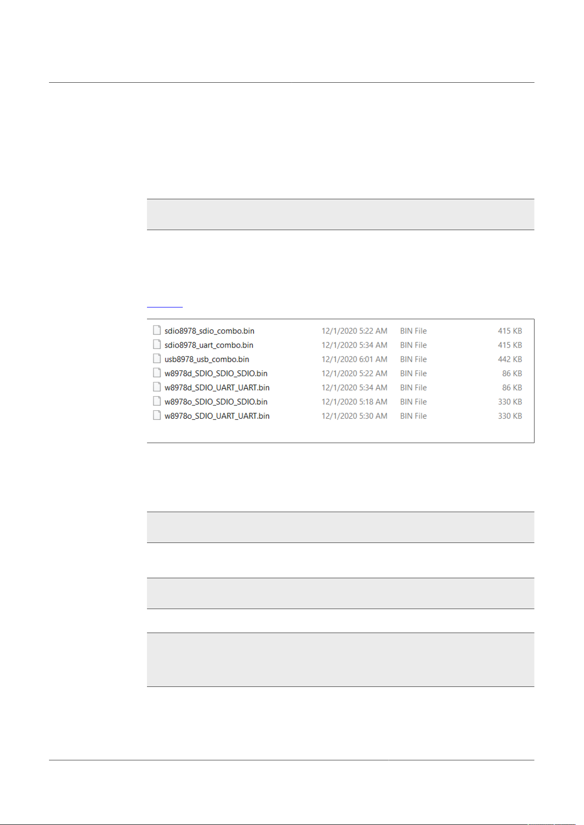
Figure 2 shows the content of FwImage directory.
UM11434
IW416 Labtool User Guide
Figure 2. FwImage directory content
Step 2: Navigate to the FwImage directory and select the MFG firmware bin file that
matches the host interface type and copy it to the Linux firmware path /lib/firmware/nxp/.
For example, the firmware binary file sdio8978_sdio_combo.bin supports both Wi-Fi and
Bluetooth over an SDIO interface. Run the commands to copy the bin file:
$ cd MFG_W8978...pxx/bin/FwImage
$ cp sdio8978_sdio_combo.bin /lib/firmware/nxp/
If there is no folder with the name nxp under /lib/firmware/ path, run the commands to
create the folder:
$ cd /lib/firmware/
$ mkdir nxp
Step 3: Go to the Bridge folder and compile the bridge application:
$ cd MFG_W8xxx...pxx/Bridge
$ tar -xzvf bridge_linux_xx.xx.xx.xx-src.tgz
$ cd bridge_linux_xx.xx.xx.xx/bridge
$ make build
The mfgbridge application executable is created in the bin_mfgbridge directory.
UM11434 All information provided in this document is subject to legal disclaimers. © NXP B.V. 2021. All rights reserved.
User manual Rev. 2 — 2 February 2021
8 / 68
Page 9

NXP Semiconductors
3.6 Loading IW416 driver and executing the firmware and bridge
The procedure to load the Wi-Fi and Bluetooth drivers and to run the Bridge application is
as follows:
Step 1: Install Wi-Fi and Bluetooth drivers.
Go to the folder which includes the Wi-Fi driver files (mlan.ko and sd8xxx.ko), and run the
following commands:
$ insmod mlan.ko
$ insmod sd8978.ko mfg_mode=1 drv_mode=1 fw_name=nxp/
sdio8978_sdio_combo.bin cal_data_cfg=none
$ dmesg
$ iwconfig
Use the dmesg command to check the driver and firmware load status. If the status
is correct the command output is as shown below. No message returns if either the
firmware or driver did not load correctly.
WLAN FW is active
wlan: Driver loaded successfully
UM11434
IW416 Labtool User Guide
Use the iwconfig command to confirm that the Wi-Fi device is defined as the mlan0
interface with the following messages:
mlan0 IEEE 802.11-DS ESSID:””
Mode:Auto channel=0 Access Point:Not-Associated
Bit Rate:0 kb/s Tx_Power=off
Retry limit:0 RTS thr=0 Fragment thr:off
Power Management:off
Link Quality=0/5 Signal level=0 dBm Noise level=0 dBm
Rx invalid nwid:0 Rx invalid crypt:0 Rx invalid frag:0
Tx excessive retries:0 Invalid misc:0 Missed beacon:0
Similarly, navigate to the folder which includes the Bluetooth driver file (bt8xxx.ko) and
execute the following commands:
$ insmod bt8xxx.ko
$ dmesg
$ hciconfig
If the status is correct the command output is as shown below. No message returns if
either the firmware or driver did not load correctly.
BT FW is active (0)
BT: Driver loaded successfully
Use the hciconfig command to confirm that the Bluetooth device is defined as the
hci0 interface with the following messages:
hci0 Type: BR/EDR Bus:SDIO
BD Address: C0:95:DA:00:43:61 ACL MTU: 1021:7 SCO MTU: 120:6
UP RUNNING PSCAN
RX bytes:824 acl:0 sco:0 events:41 errors:0
TX bytes:1168 acl:0 sco:0 events:41 errors:0
UM11434 All information provided in this document is subject to legal disclaimers. © NXP B.V. 2021. All rights reserved.
User manual Rev. 2 — 2 February 2021
9 / 68
Page 10

NXP Semiconductors
If the Bluetooth is down, try to reset the Bluetooth interface to hci0 or disconnect IW416
board. Unload the drivers with the following commands:
$ rmmod sd8xxx.ko
$ rmmod mlan.ko
$ rmmod bt8xxx.ko
Step 2: Configure the DUT IP address.
We use the following IP addresses as examples in the commands shown for this step:
• (Linux) Bridge computer IP address: 192.168.0.10
• (Windows) Host computer IP address: 192.168.0.58
In the Linux system, configure the Ethernet IP address with the following command:
>ifconfig -a
Check the Ethernet name. The following command assumes the Ethernet name is ethx :
>ifconfig ethx 192.168.0.10
UM11434
IW416 Labtool User Guide
Check the Ethernet connection state between the (Windows) Host computer and the
(Linux) Bridge computer using the ping command.
In the Windows Terminal window, execute the following command:
>ping 192.168.0.10
In the Linux platform terminal execute the following command:
>ping 192.168.0.58
Ensure that both the (Windows) Host computer and (Linux) Bridge computer IP
addresses are under the same subnet.
Step 3: Run the bridge application.
Go to the bridge folder under the MFG release package where the bridge application was
compiled previously, and run the bridge application with the following command:
$./mfgbridge
To terminate the bridge application, type CTRL+C in the bridge window.
To restart the bridge application, execute the ./mfgbridge command again.
UM11434 All information provided in this document is subject to legal disclaimers. © NXP B.V. 2021. All rights reserved.
User manual Rev. 2 — 2 February 2021
10 / 68
Page 11
NXP Semiconductors
4 Windows PC setup
4.1 Labtool setup on Windows PC
The Host computer runs on Windows operating system (64 bit and 32 bit). The procedure
to set up the environment is as follows:
Step 1: Download the MFG software release package MFG-W8xxx...pax.bin published
on IW416 Tools and Software tab on NXP website. The MFG software release package
includes the MFG firmware, the Labtool executable (.exe file), and the MFG bridge
application. All three software items are needed for Labtool testing.
Step 2: Unzip the MFG firmware software release.
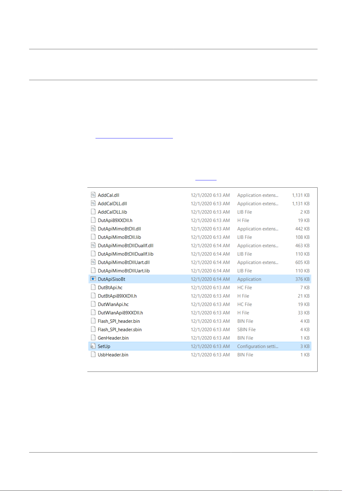
Step 3 - Copy the ...bin/release/labtool folder to the Host computer and make sure the
path length has less than 255 characters. Figure 3 shows the labtool repository content:
UM11434
IW416 Labtool User Guide
Figure 3. Labtool Repository Content
Step 4: Disable the Windows firewall.
Step 5: Open the Network and Sharing Center on the Windows PC. Change the network
address of the Ethernet port to the same subnet as the (Linux) Bridge computer. The
following IP addresses are used in this document:
• (Windows) Host computer: 192.168.0.58
• (Linux) Bridge computer: 192.168.0.10
UM11434 All information provided in this document is subject to legal disclaimers. © NXP B.V. 2021. All rights reserved.
User manual Rev. 2 — 2 February 2021
11 / 68
Page 12

NXP Semiconductors
Step 6: Open the SetUp.ini file using a text editor. The value of the parameter
DutIpAddress is the IP address of the DUT. The parameter HostIpAddress is the IP
address of the Windows PC. Edit the file as follows:
[DutIp]
DutIpAddress = 192.168.0.10
HostIpAddress = 192.168.0.58
Protocol = TCP
Step 7: In the SetUp.ini file, the parameter NO_EEPROM is used to specify the calibration
data storage option. The default value is 1 (Use calibration data from the external
configuration file).
For general RF evaluation and test, set the file option to 1 to use the calibration data
from an external file. If the calibration data is already stored in the OTP memory of IW416
device, set the value to 2.
[DutInitSet]
0 = EEPROM support
1 = No_EEPROM support
2 = OTP support
NO_EEPROM = 1
NoEepromBtFlexFileName = WlanCalData_ext.conf
NoEepromWlanFlexFileName = WlanCalData_ext.conf
UM11434
IW416 Labtool User Guide
Note: No_EEPROM support refers to the calibration data from the external configuration
file.
Step 8: Save the “SetUp.ini” file after making the changes.
UM11434 All information provided in this document is subject to legal disclaimers. © NXP B.V. 2021. All rights reserved.
User manual Rev. 2 — 2 February 2021
12 / 68
Page 13
NXP Semiconductors
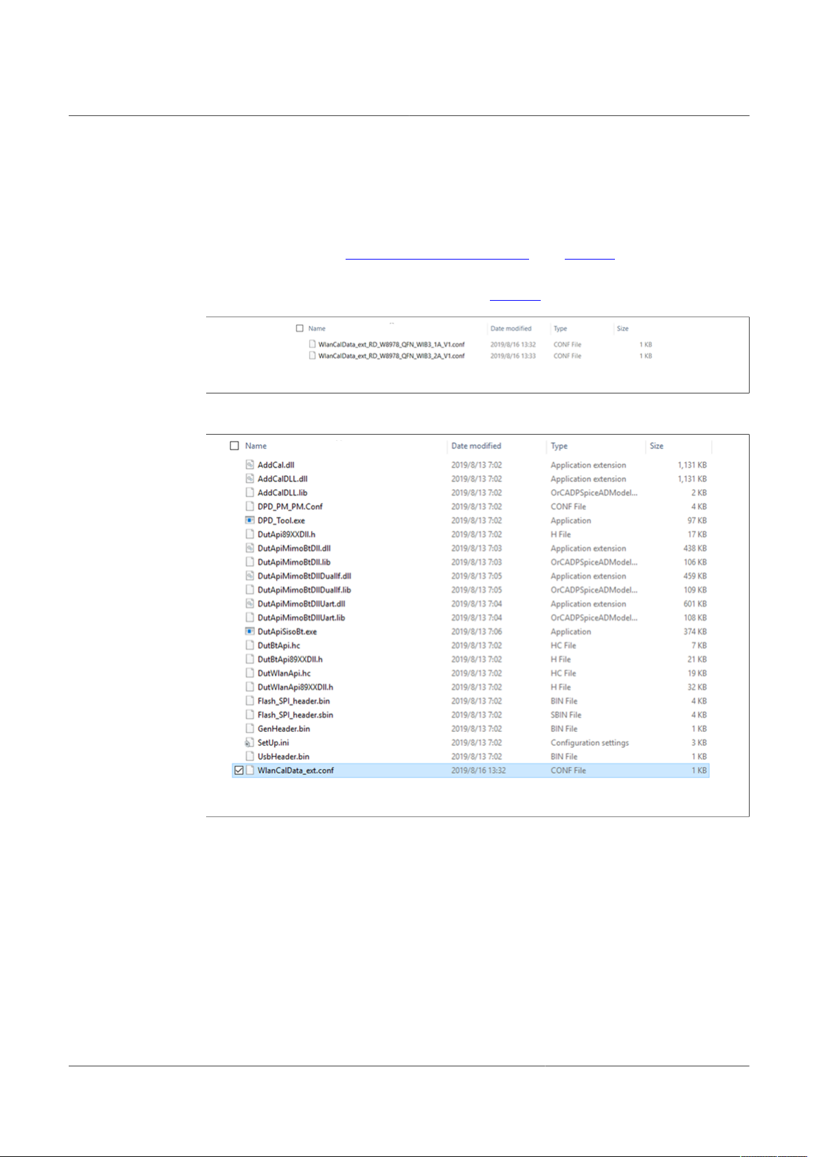
4.2 Calibration data
The DUT requires calibration data for optimal performance. The calibration data is
included in the .conf file or programmed into the on-chip OTP memory of IW416 device.
The .conf file is included in the reference design package for the WLCSP and QFN
packages available on IW416 Tools and Software tab. See Figure 4.
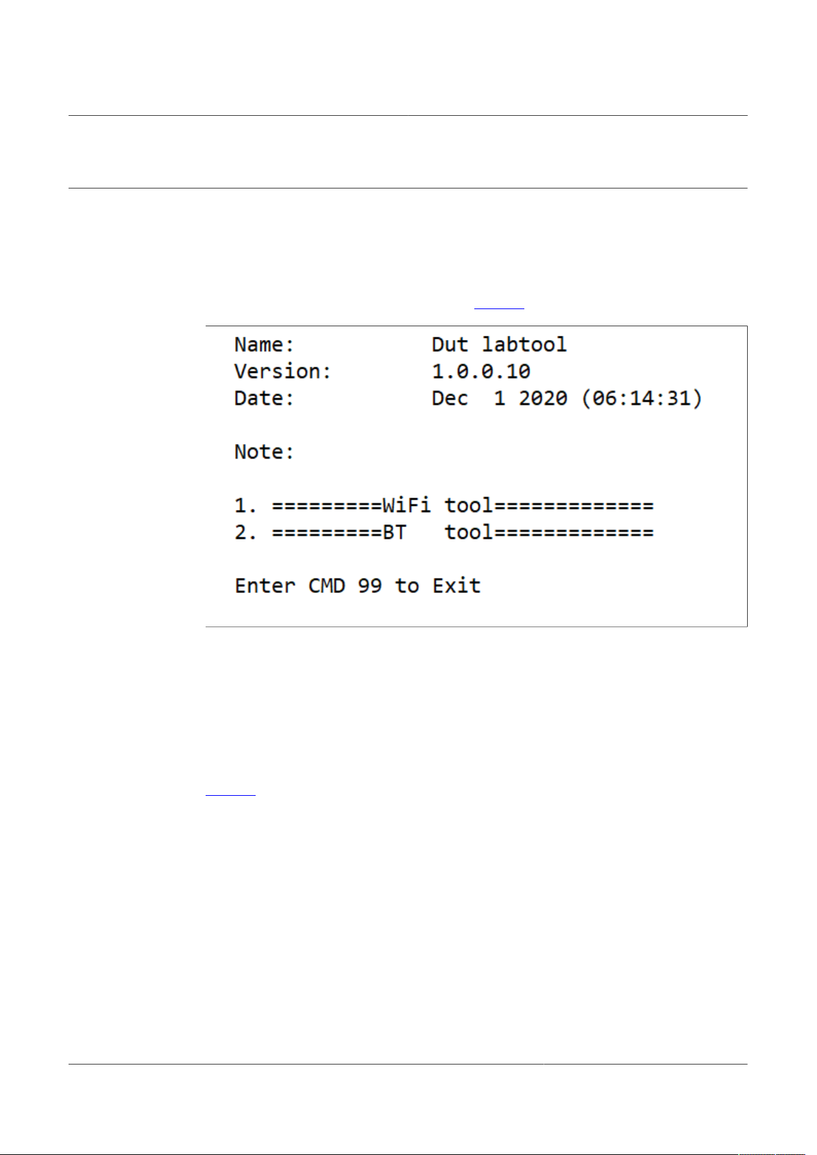
Before launching the Labtool, copy the .conf file into the Labtool working directory and
rename the file as WlanCalData_ext.conf (see Figure 5).
Figure 4. Calibration data file (.conf)
UM11434
IW416 Labtool User Guide
Figure 5. WlanCalData_Ext.conf in Labtool directory
UM11434 All information provided in this document is subject to legal disclaimers. © NXP B.V. 2021. All rights reserved.
User manual Rev. 2 — 2 February 2021
13 / 68
Page 14
NXP Semiconductors
5 Labtool usage
5.1 Starting Labtool
Ensure the bridge application is running prior to starting the Labtool application. The
procedure to start the Labtool application is as follows:
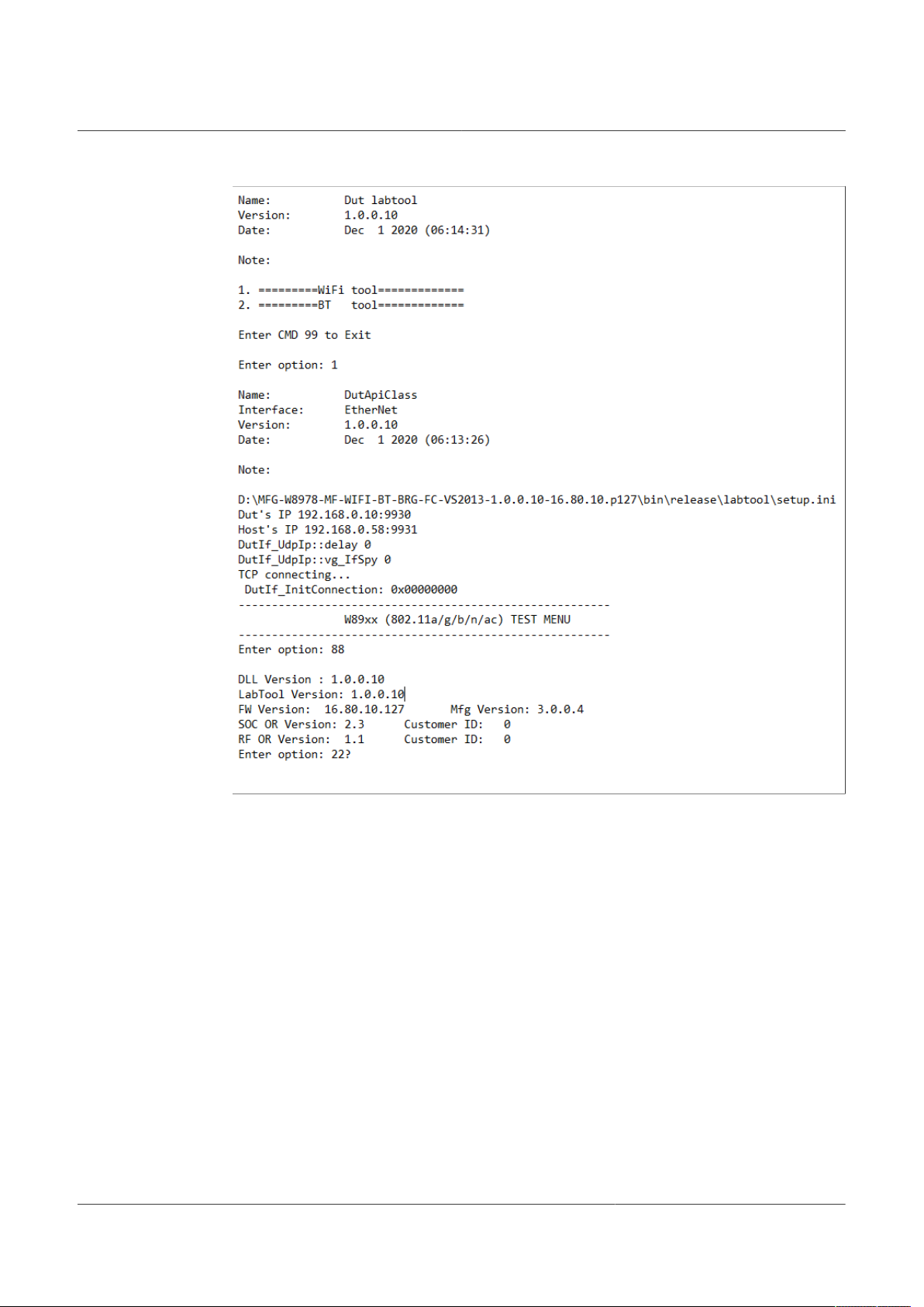
Step 1: Double-click on DutApiSisoBt.exee. Figure 6 shows the Labtool start window:
UM11434
IW416 Labtool User Guide
Figure 6. Labtool start window
Step 2: At the command prompt, enter “1” to start the Wi-Fi radio operation or “2” to start
the Bluetooth radio operation.
Step 3: To confirm whether the bridge and host setups are working properly, issue the
command 88 to check the firmware and Labtool version number.
• If the correct version numbers are returned, start the RF test procedure.
• If the version numbers are incorrect, check the host, DUT, and bridge connections.
Confirm the Wi-Fi and Bluetooth drivers are installed correctly.
Figure 7 shows the correct state of command 88 execution.
UM11434 All information provided in this document is subject to legal disclaimers. © NXP B.V. 2021. All rights reserved.
User manual Rev. 2 — 2 February 2021
14 / 68
Page 15
NXP Semiconductors
UM11434
IW416 Labtool User Guide
Figure 7. Command 88 execution
UM11434 All information provided in this document is subject to legal disclaimers. © NXP B.V. 2021. All rights reserved.
User manual Rev. 2 — 2 February 2021
15 / 68
Page 16
NXP Semiconductors
5.2 Running commands
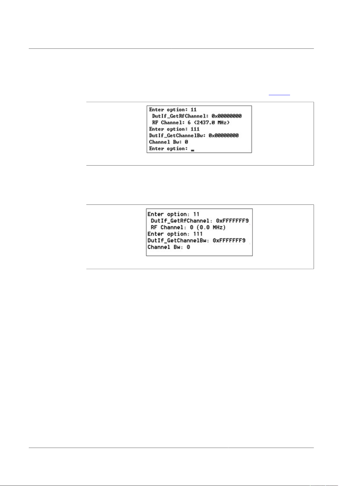
Each time a Labtool command is executed, the console returns a status byte. A
successful command execution is indicated by a status byte with all 0s (Figure 8).
Figure 8. Status – Successful command execution
A failed command returns invalid data and is indicated by a non-0 status byte
(0x00000001 to 0xFFFFFFFF). This could indicate a problem with the communication to
the DUT, incorrect firmware, no firmware download, wrong version of Labtool/firmware,
and so on.
UM11434
IW416 Labtool User Guide
Figure 9. Status – Failed command execution
When using the transmit commands (25, 33, 35), note that all the Very High Throughput
(VHT) rates are not available for all bandwidth and antenna path combinations. An error
code in the returned status byte of 0xE indicates that the rate is not supported by the
DUT. Enter a “?” at the Labtool prompt to list all the available commands.
5.3 Closing Labtool
To close Labtool, issue Command 99 once.
To quit Labtool, issue command 99 twice.
5.4 Getting help
The Labtool application realizes its functions (such as enable Tx/Rx tests) through the
related Labtool commands. Labtool commands are listed in the Command Line Interface
(CLI) menu.
Enter ? at the command prompt in the main window to get the CLI menu.
Enter <command number>? for the detailed usage and help menu for the respective
command.
For example, enter 10?.to get the detailed Command 10 usage (including the command
options) and related help file are shown in the main window.
UM11434 All information provided in this document is subject to legal disclaimers. © NXP B.V. 2021. All rights reserved.
User manual Rev. 2 — 2 February 2021
16 / 68
Page 17
NXP Semiconductors
6 Wi-Fi Labtool commands
Table 2. Wi-Fi Labtool command summary
Command
Command 9: Get Tx/Rx antenna configuration (valid when Antenna diversity is supported)
Command 10: Set Tx/Rx antenna configuration (valid when Antenna diversity is supported)
Command 11: Get RF channel configuration
Command 12: Set RF channel configuration
Command 13: Get RF data rate
Command 18: Set transmitter in CW mode
Command 22: Set power at antenna using calibration data
Command 25: Transmit with duty cycle Tx mode
Command 29: Get RF band configuration
Command 30: Set RF band configuration
Command 31: Clear Rx packet count
Command 32: Get and clear Rx packet count
Command 33: Transmit multicast packets
Command 34: Enable/disable BSSID filter
Command 35: Transmit with SIFS gap
Command 38: Transmit unicast packet
Command 44: Storage type get/set function
Command 45: Read MAC address from OTP
Command 46: Write MAC address to OTP
Command 53: Set calibration data to storage from text file
Command 54: Get calibration data from storage into file
Command 88: Get firmware/hardware version
Command 95: Get XTAL calibration offset
Command 96: Set XTAL calibration offset
Command 99: Exit Labtool application
Command 111: Get channel bandwidth
Command 112: Set channel bandwidth
Command 144: Read OTP raw data
Command 146: Get the number of calibrations done on OTP
Command 147: Get free lines in OTP
Command 148: Write patch block to OTP
Command 149: Write user data to OTP
Command 198: Start RSSI data collection
Command 199: Stop RSSI data collection and report result
UM11434
IW416 Labtool User Guide
UM11434 All information provided in this document is subject to legal disclaimers. © NXP B.V. 2021. All rights reserved.
User manual Rev. 2 — 2 February 2021
17 / 68
Page 18

NXP Semiconductors
6.1 Command 9: Get Tx/Rx antenna configuration (valid when Antenna diversity is supported)
This command is used to check which antenna is connected to the Wi-Fi radio when
more than one antenna is used for Antenna diversity application.
Syntax: 9
Return data: GetTxAntenna: Antenna X (where X = 1 or 2)
6.2 Command 10: Set Tx/Rx antenna configuration (valid when Antenna diversity is supported)
This command is used to set the desired antenna to the Wi-Fi radio when more than one
antenna is used for Antenna diversity application
Syntax: 10 <antenna number>
Where:
Command parameter Description
antenna number Number used to qualify the Tx/Rx antenna
UM11434
IW416 Labtool User Guide
1 = Main
2 = Aux
Example
10 1 // Sets the main antenna
Return data:
• Successful command: all-0 status byte (0x00000000)
• Failed command: non-0 status byte (0x00000001 to 0xFFFFFFFF)
UM11434 All information provided in this document is subject to legal disclaimers. © NXP B.V. 2021. All rights reserved.
User manual Rev. 2 — 2 February 2021
18 / 68
Page 19

NXP Semiconductors
6.3 Command 11: Get RF channel configuration
This command returns the values of the current RF channel, such as channel and offset.
Syntax: 11
Return data
Channel: Current channel number (see Section 8.1 "RF channels")
Offset: Boundary (applicable to non-20 MHz bandwidth channel)
• 0x1 = lower boundary of channel
• 0x3 = upper boundary of channel
Offset = 1 indicates that the channel number displayed (or set, in the case of Command
12) is the lower boundary of the channel.
If the channel bandwidth is 40 MHz (2.4 GHz band) and the channel center is 8, the
Labtool reports Ch 6 with offset 1 or Ch 10 with offset 3.
6.4 Command 12: Set RF channel configuration
UM11434
IW416 Labtool User Guide
This command sets the RF channel. Specify the RF channel in the appropriate band (2.4
GHz or 5 GHz) or an error will occur.
Syntax: #23 <channel>
Where:
Command parameter Description
Channel Channel number
When 40 MHz bandwidth is enabled, then the channel specified is the
left most/lower channel.
Examples
12 6 // Sets Ch 6 in 20 MHz bandwidth mode
112 1 // Sets to 40 MHz bandwidth
12 36 // Sets Ch 36 with offset 1 (Ch 36 + Ch 40 boned pair)
12 6 // Sets Ch 6 in 20 MHz bandwidth mode
112 1 // Sets to 40 MHz bandwidth
12 40 // Sets Ch 40 with offset 3 (Ch 36 + Ch 40 bonded pair)
Return data:
• Successful command: all-0 status byte (0x00000000)
• Failed command: non-0 status byte (0x00000001 to 0xFFFFFFFF)
UM11434 All information provided in this document is subject to legal disclaimers. © NXP B.V. 2021. All rights reserved.
User manual Rev. 2 — 2 February 2021
19 / 68
Page 20

NXP Semiconductors
6.5 Command 13: Get RF data rate
This command is used to check the current data rate set for the Wi-Fi radio.
Syntax: 13
Example(s)
13 // reads back current data rate for Wi-Fi radio
Return data: DataRate: X // Where X is the number associated with the data rate. See
Table 3
Table 3. RF data rates
UM11434
IW416 Labtool User Guide
DataRate (X) RF data rate
1 1M
2 2M
3 5.5M
4 11M
5 22M
6 6M
7 9M
8 12M
9 18M
10 24M
11 36M
12 48M
13 54M
14 72M
15 MCS0
16 MCS1
17 MCS2
18 MCS3
19 MCS4
20 MCS5
21 MCS6
22 MCS7
47 MCS32
UM11434 All information provided in this document is subject to legal disclaimers. © NXP B.V. 2021. All rights reserved.
User manual Rev. 2 — 2 February 2021
20 / 68
Page 21
NXP Semiconductors
6.6 Command 18: Set transmitter in CW mode
This command transmits an un-modulated carrier as a Continuous Wave (CW) tone.
Syntax: 18 <Enable>
Where:
Command parameter Description
Enable Mode enable
Examples
18 1 // Turns on transmission
18 0 // Turns off transmission
Return data:
• Successful command: all-0 status byte (0x00000000)
• Failed command: non-0 status byte (0x00000001 to 0xFFFFFFFF)
UM11434
IW416 Labtool User Guide
0 = disable (default)
1 = enable
6.7 Command 22: Set power at antenna using calibration data
This command sets the Tx power at the antenna using stored calibration data.
Syntax: 22 <channel> <power level> <modulation> <forceCalData>
Where:
Command parameter Description
channel Tx Channel
See Section 8.1. Default = Ch 6.
power level Tx Power Level (dBm)
modulation Modulation
00 = 802.11b CCK (default)
01 = 802.11g/a/p OFDM
10 = 802.11n MCS
forceCalData Force calibration data
Valid only for NO_EEPROM mode
0 = download calibration data only if not downloaded yet (default)
1 = force configuration file to be downloaded
Example
22 6 13 1 1 // Sets power for Ch 6, 13 dBm transmit power with OFDM modulation
rates, and forces the configuration file download
Return data:
• Successful command: all-0 status byte (0x00000000)
• Failed command: non-0 status byte (0x00000001 to 0xFFFFFFFF)
UM11434 All information provided in this document is subject to legal disclaimers. © NXP B.V. 2021. All rights reserved.
User manual Rev. 2 — 2 February 2021
21 / 68
Page 22

NXP Semiconductors
6.8 Command 25: Transmit with duty cycle Tx mode
This command enables the device in modulated, packet-based, fixed duty cycle transmit
mode after the power is manually set.
Syntax: 25 <enable> <data rate> <PayLoadWeight> <ShortGI>
<AdvCoding> <TxBfOn> <GFMode> <STBC> <PowerID> <SignalBw>
Where:
Command parameter Description
enable Mode enable
data rate Data Rate
PayLoadWeight Represents a payload duty percentage (default = 50)
ShortGI Short guard interval
AdvCoding Advanced Coding
TxBfOn Tx Beamform On
GFMode Greenfield mode
PowerID Power ID
SignalBW Signal bandwidth
UM11434
IW416 Labtool User Guide
0 = disable (default)
1 = enable
See Section 8.2 "Data rates" for mapping. Default = 4
Pattern = 0xB496DEB6
Short Preamble = 0 | 1 (default =0)
0 = long guard interval (default)
1 = short guard interval
0 = BCC (default)
1 = LDPC
0 = disable (default)
1 = enable
0 = disable (default)
1 = enable
Set to -1
See Section 6.7 "Command 22: Set power at antenna using calibration
data" for Power ID mapping.
0 = 20 MHz
1 = 40 MHz
-1 = follow deviceBW as in Section 6.3 "Command 11: Get RF channel
configuration" and Section 6.4 "Command 12: Set RF channel
configuration" (default)
Examples
25 1 4 // Turns on transmitter and specifies data rate (11 Mbit/s)
25 0 // Turns off transmitter
Return data:
• Successful command: all-0 status byte (0x00000000)
• Failed command: non-0 status byte (0x00000001 to 0xFFFFFFFF)
UM11434 All information provided in this document is subject to legal disclaimers. © NXP B.V. 2021. All rights reserved.
User manual Rev. 2 — 2 February 2021
22 / 68
Page 23

NXP Semiconductors
6.9 Command 29: Get RF band configuration
This command gets the RF band configuration.
Syntax: 29
Return data: Current RF band
• 0 = 2.4 GHz
• 1 = 5 GHz
6.10 Command 30: Set RF band configuration
This command sets the RF band configuration.
Syntax: 30 <band>
Where:
Command parameter Description
band RF band
UM11434
IW416 Labtool User Guide
0 = 2.4 GHz (default)
1 = 5 GHz
Examples
30 0 // Sets 2.4 GHz band
30 1 // Sets 5 GHz band
Return data:
• Successful command: all-0 status byte (0x00000000)
• Failed command: non-0 status byte (0x00000001 to 0xFFFFFFFF)
6.11 Command 31: Clear Rx packet count
This command clears the packet count register (start Rx Frame Error Rate (FER) test).
The receiver continuously counts the received multi-cast packets.
Syntax: 31
Return data:
• Successful command: all-0 status byte (0x00000000)
• Failed command: non-0 status byte (0x00000001 to 0xFFFFFFFF)
6.12 Command 32: Get and clear Rx packet count
This command gets the counts for Rx, multi-cast and error packets, and clears the Rx
packet counter (stop Rx FER test).
Syntax: 32
Return data: Displays the received multi-cast packet count
UM11434 All information provided in this document is subject to legal disclaimers. © NXP B.V. 2021. All rights reserved.
User manual Rev. 2 — 2 February 2021
23 / 68
Page 24

NXP Semiconductors
6.13 Command 33: Transmit multicast packets
This command transmits a specific number of multicast packets. It is used for measuring
Rx sensitivity if connected to another radio module, such as a receiver
Syntax: 33 <Len> <Count> <Rate> <Pattern> <ShortPreamble>
<ActSubCh> <ShortGI> <AdvCoding> <TxBfOn> <GFMode> <STBC>
<PowerID> <SignalBw> <BSSID>
Where:
Command parameter Description
Len Packet byte length
Count Packet count
Rate Data rate
Pattern Packet data pattern
ShortPreamble Short preamble
ActSubCh Active sub channel
ShortGI Guard interval (GI) length
AdvCoding Advanced coding
TxBfOn Tx Beamform On
GFMode Greenfield mode
STBC Space-time block code
PowerID Power ID
UM11434
IW416 Labtool User Guide
Default is 0x400
Default is 0x64
See Section 8.2 "Data rates". Default is 4.
Default is 0xB496DEB6
0 = long preamble
1 = short preamble (default)
00 = low
01 = upper
10 = both
11 = both (default)
0 = long GI (default)
1 = short GI
0 = BCC (default)
1 = LDPC
0 = disable (default)
1 = enable
0 = disable (default)
1 = enable
0 = disable (default)
1 = enable
Set to -1. See Section 6.7 "Command 22: Set power at antenna using
calibration data" for Power ID mapping
UM11434 All information provided in this document is subject to legal disclaimers. © NXP B.V. 2021. All rights reserved.
User manual Rev. 2 — 2 February 2021
24 / 68
Page 25

NXP Semiconductors
Command parameter Description
SignalBW Signal Bandwidth
BSSID Basic Service Set ID
Example
33 400 64 4 // Transmits 100 multicast packets with 1024-byte payload at data rate of
11 Mbit/s
Return data:
• Successful command: all-0 status byte (0x00000000)
• Failed command: non-0 status byte (0x00000001 to 0xFFFFFFFF)
UM11434
IW416 Labtool User Guide
-1 = follows deviceBW as in Section 6.26 "Command 111: Get channel
bandwidth" and Section 6.27 "Command 112: Set channel bandwidth"
(default)
0x0 = 20 MHz
0x1 = 40 MHz
The format is xx.xx.xx.xx.xx.xx. If is not set, all 0xFs will be used.
6.14 Command 34: Enable/disable BSSID filter
This command is used to enable/disable BSSID filter for the Wi-Fi receiver test.
Syntax: 34 <mode> <BSSID>
Where:
Command parameter Description
mode Number associated with the mode
0 = set the receiver in promiscuous mode
1 = enable BSSID filter
2 = read BSSID register settings (default)
3 = disable promiscuous mode
4 = disable BSSID filter
BSSID Hex number representing the basic service set ID: xx.xx.xx.xx.xx.xx (x
must be a Hex Number)
Example(s)
34 1 66.77.88.99.AA.BB // enables BSSID filter for BSSID = 66.77.88.99.AA.BB
Return data:
• Successful command: all-0 status byte (0x00000000)
• Failed command: non-0 status byte (0x00000001 to 0xFFFFFFFF)
UM11434 All information provided in this document is subject to legal disclaimers. © NXP B.V. 2021. All rights reserved.
User manual Rev. 2 — 2 February 2021
25 / 68
Page 26

NXP Semiconductors
6.15 Command 35: Transmit with SIFS gap
This command continuously transmits standard 802.11 packets with an adjustable time
gap specified by a configurable Short Interframe Space (SIFS) interval of 0 to 250 µs.
Syntax: 35 <Enable> <Rate> <AdjustTxBurstGap> <BurstSifsInUs>
<Packet Length> <Pattern> <ShortPreamble> <ActSubCh> <ShortGI>
<AdvCoding> <TxBfOn> <GFMode> <STBC> <DPD> <PowerID> <SignalBw>
<BSSID>
Where:
Command parameter Description
Enable Mode enable
Rate Data Rate
AdjustTxBurstGap Adjust Tx burst gap
BurstSifsInUs Burst SIFS (μs)
Packet Length Packet byte length (in hexadecimal)
Pattern Packet data pattern
ShortPreamble Short preamble
ActSubCh Active sub channel
ShortGI Short guard interval (GI)
AdvCoding Advanced coding
TxBfOn Tx Beamform On
UM11434
IW416 Labtool User Guide
0 = disable (default)
1 = enable
See Section 8.2 "Data rates" for mapping.
Some data rates are only available in some channel bandwidth modes.
Default is 4.
0 = disable (default)
1 = enable
Minimum is 16 μs. Maximum is 10 ms.
Maximum length is 15 KB (Kilobytes), or 0x3A98 in hexadecimal.
Default is 0xB496DEB6
0 = long preamble
1 = short preamble (default)
00 = low
01 = upper
10 = both
11 = both (default)
0 = long GI (default)
1 = short GI
0 = BCC (default)
1 = LDPC
0 = disable (default)
1 = enable
UM11434 All information provided in this document is subject to legal disclaimers. © NXP B.V. 2021. All rights reserved.
User manual Rev. 2 — 2 February 2021
26 / 68
Page 27

NXP Semiconductors
Command parameter Description
GFMode Greenfield Mode
STBC Space-time block code
DPD Deep power down (DPD)
PowerID Power ID
SignalBW Signal bandwidth
BSSID Basic Service Set ID
UM11434
IW416 Labtool User Guide
0 = disable (default)
1 = enable
0 = disable (default)
1 = enable
0 = disable (default)
1 = enable
Set to -1. See Section 6.7 "Command 22: Set power at antenna using
calibration data" for Power ID mapping.
-1 = follows deviceBW as in in Section 6.26 "Command 111: Get
channel bandwidth" and Section 6.27 "Command 112: Set channel
bandwidth" (default)
0x0 = 20 MHz
0x1 = 40 MHz
The format is xx.xx.xx.xx.xx.xx. If is not set, all 0xFs will be used.
Examples
35 1 13 1 20 400 // Transmits a 1024-byte packet at 54 Mbps with a SIFS gap of
20 μs.
35 1 22 1 45 200 // Transmits a 512-byte packet at HT_MCS7 with a SIFS gap of
45 μs.
35 0 // Turns off transmission with SIFS Interval.
35 1 4 1 150 100 AA 1 3 0 0 0 0 0 0 -1 1.22.33.44.55.66 // Set duty
cycle transmit with SIFS gap of 150 μs at 11 Mbit/s and 256 bytes with data pattern “AA”
and MAC is 11.22.33.44.55.66.
Return data:
• Successful command: all-0 status byte (0x00000000)
• Failed command: non-0 status byte (0x00000001 to 0xFFFFFFFF)
UM11434 All information provided in this document is subject to legal disclaimers. © NXP B.V. 2021. All rights reserved.
User manual Rev. 2 — 2 February 2021
27 / 68
Page 28
NXP Semiconductors
6.16 Command 38: Transmit unicast packet
This command transmits a specified number of unicast packets.
Syntax: 38 <Len> <Count> <Rate> <Pattern> <TxBfOn> <SLP>
<SignalBW> <PowerID> <BSSID>
Where:
Command parameter Description
Len Packet Length (in hexadecimal)
Count Packet count (in hexadecimal)
Rate Data rate
Pattern Pattern
TxBfOn Tx Beamform on
SLP Service location protocol (SLP) parameter used to enable/disable
SignalBw Signal bandwidth
PowerID Power ID
BSSID Basic Service Set ID
UM11434
IW416 Labtool User Guide
Default is 0x400.
Default is 0x64.
See Section 8.2 "Data rates" for mapping.
Some data rates are only available in some channel bandwidth modes.
Default is 4.
Default is 0xB496DEB6 for MFG testing
0 = disable (default)
1 = enable
steering
0 = disable
1 = enable (default)
0 = 20 MHz
1 = 40 MHz
-1 = follow deviceBW as in Section 6.26 "Command 111: Get channel
bandwidth" and Section 6.27 "Command 112: Set channel bandwidth"
(default)
Set to -1. See Section 6.7 "Command 22: Set power at antenna using
calibration data" for Power ID mapping
The format is xx.xx.xx.xx.xx.xx. If is not set, all 0xFs will be used.
Example
38 400 64 4 AA 1 1 -1 -1 00.50.43.11.22.33 // Transmits 100 unicast
packets with 1024-byte payload at data rate of 11 Mbps, data pattern “AA”, enables SLP,
and MAC is 00.50.43.11.22.
Return data:
• Successful command: all-0 status byte (0x00000000)
• Failed command: non-0 status byte (0x00000001 to 0xFFFFFFFF)
UM11434 All information provided in this document is subject to legal disclaimers. © NXP B.V. 2021. All rights reserved.
User manual Rev. 2 — 2 February 2021
28 / 68
Page 29

NXP Semiconductors
6.17 Command 44: Storage type get/set function
This command gets/sets the storage type for Read/Write during the Labtool session.
Syntax: 44 <Type>
Where:
Command parameter Description
Type Storage Type
Examples
44 // Reads back storage type
44 1 // Sets the storage type to configuration file
Return data: Storage type if there is no option in the command.
6.18 Command 45: Read MAC address from OTP
UM11434
IW416 Labtool User Guide
01 = NO_EPPROM (see configuration calibration file)
10 = OTP
This command returns the MAC address. Before this operation, the storage type must set
to OTP.
Syntax: 45
Return data: MAC address
UM11434 All information provided in this document is subject to legal disclaimers. © NXP B.V. 2021. All rights reserved.
User manual Rev. 2 — 2 February 2021
29 / 68
Page 30

NXP Semiconductors
6.19 Command 46: Write MAC address to OTP
Command 46 writes the MAC address. Before this operation, the storage type must set
to OTP.
Syntax: 46 <MAC Address>
Where:
Command parameter Description
MAC Address MAC address in xx.xx.xx.xx.xx.xx format
Example
46 C0.95.DA.00.43.61 // Writes MAC address C0.95.DA.00.43.61 to OTP
Return data:
• Successful command: all-0 status byte (0x00000000)
• Failed command: non-0 status byte (0x00000001 to 0xFFFFFFFF)
UM11434
IW416 Labtool User Guide
6.20 Command 53: Set calibration data to storage from text file
This command sets the calibration data to storage from the following calibration data text
files:
• CalWlanDataFile.txt
• CalBtDataFile.txt
• PwrTble_Path0.txt
When the storage type is set to OTP, this command loads the calibration data generated
from the text files into OTP.
Syntax: 53
Examples
44 1 // Set NO_EEPROM as storage type
53 // Generate calibration configuration file “WlanCalData_ext.conf”
from the text files
44 2 // Set OTP as storage type
53 // Generate calibration configuration file “WlanCalData_ext.conf”
from the text files and load into OTP memory
Return data:
• Successful command: all-0 status byte (0x00000000)
• Failed command: non-0 status byte (0x00000001 to 0xFFFFFFFF)
UM11434 All information provided in this document is subject to legal disclaimers. © NXP B.V. 2021. All rights reserved.
User manual Rev. 2 — 2 February 2021
30 / 68
Page 31

NXP Semiconductors
6.21 Command 54: Get calibration data from storage into file
This command gets the calibration data from storage and saves it to the following text
files:
• CalWlanDataFile_Upload.txt
• CalBtDataFile_Upload.txt
• PwrTble_Path0_Upload.txt
These text files allow users to edit parameters, such as XTAL and FEM_Loss.
Syntax: 54
Example
44 1 // Set NO_EEPROM as storage type
54 // Generate text files from calibration configuration file
Return data:
• CalWlanDataFile_Upload.txt
• CalBtDataFile_Upload.txt
• PwrTble_Path0_Upload.txt
UM11434
IW416 Labtool User Guide
6.22 Command 88: Get firmware/hardware version
This command returns the firmware, hardware, and Labtool versions.
Syntax: 88
Return data:
• DLL Version: 1.0.0.10
• Labtool Version: 1.0.0.10
• FW Version: 16.80.10.127
• Mfg Version: 3.3.0.4
• SoC OR Version: 2.3 Customer ID: 0
• RF OR Version: 1.1 Customer ID: 0
6.23 Command 95: Get XTAL calibration offset
This command gets the 8-bit crystal calibration offset.
Syntax: 95
Return data XTAL: 80
UM11434 All information provided in this document is subject to legal disclaimers. © NXP B.V. 2021. All rights reserved.
User manual Rev. 2 — 2 February 2021
31 / 68
Page 32

NXP Semiconductors
6.24 Command 96: Set XTAL calibration offset
This command sets the 8-bit crystal calibration offset to adjust the frequency offset when
viewed on a Vector Signal Analyzer (VSA), a spectrum analyzer, or a frequency counter.
Syntax: 96 <XTAL offset value>
Where:
Command parameter Description
XTAL offset value Crystal offset value comprised between 0x00 and 0xFF
Example(s)
96 AA // Sets crystal offset value to 0xAA.
Return data:
• Successful command: all-0 status byte (0x00000000)
• Failed command: non-0 status byte (0x00000001 to 0xFFFFFFFF)
UM11434
IW416 Labtool User Guide
6.25 Command 99: Exit Labtool application
This command exits either the Wi-Fi or Bluetooth menu. A second Command 99 will exit
the Labtool and close the command prompt window.
Syntax: 99
Return data: --
6.26 Command 111: Get channel bandwidth
This command returns the channel bandwidth in use.
Syntax: 111
Return data: Channel bandwidth
• 0x0 = 20 MHz
• 0x1 = 40 MHz
UM11434 All information provided in this document is subject to legal disclaimers. © NXP B.V. 2021. All rights reserved.
User manual Rev. 2 — 2 February 2021
32 / 68
Page 33

NXP Semiconductors
6.27 Command 112: Set channel bandwidth
This command sets the channel bandwidth.
Syntax: 112 <Bandwidth>
Where:
Command parameter Description
Bandwidth Bandwidth
Examples
112 0 // Sets the channel bandwidth to 20 MHz
112 1 // Sets the channel bandwidth to 40 MHz
Return data:
• Successful command: all-0 status byte (0x00000000)
• Failed command: non-0 status byte (0x00000001 to 0xFFFFFFFF)
UM11434
IW416 Labtool User Guide
0x0 = 20 MHz
0x1 = 40 MHz
6.28 Command 144: Read OTP raw data
This command reads the OTP raw data.
Syntax: 144 <Line>
Where:
Command parameter Description
Line Specifies the line to read in OTP
Examples
144 0 // Reads all raw data in OTP
144 1 // Reads raw data of 16th line in OTP
Return data: Raw data in OTP
6.29 Command 146: Get the number of calibrations done on OTP
This command is used to check how many times the device was calibrated based on the
number of calibration data sets stored in the on-chip OTP memory.
Syntax: 146
Example
146 // reads back the number of calibrations stored in the OTP
## ## // description of what the example does
Return data: Number of calibration DONE on OTP: X // (X is the number of
calibrations performed)
UM11434 All information provided in this document is subject to legal disclaimers. © NXP B.V. 2021. All rights reserved.
User manual Rev. 2 — 2 February 2021
33 / 68
Page 34

NXP Semiconductors
6.30 Command 147: Get free lines in OTP
This command checks and returns the free lines in OTP.
Syntax: 147
Return data: Free lines on OTP
6.31 Command 148: Write patch block to OTP
This command writes the special binary file patch into OTP. For example, the regulatory
power table bin file is programmed into OTP using this command.
Syntax: 148 <Bin File>
Where:
Command parameter Description
Bin File Name of the binary file to be written into OTP
UM11434
IW416 Labtool User Guide
If left blank, default patch block file “PatchBlockFileOTP.bin” is used.
Return data:
• Successful command: all-0 status byte (0x00000000)
• Failed command: non-0 status byte (0x00000001 to 0xFFFFFFFF)
6.32 Command 149: Write user data to OTP
This command writes the user data bin file into OTP.
Syntax: 149 <User Data>
Where:
Command parameter Description
User Data User Bin File to be Written into OTP
If left blank, default user data file “UserDataFileOTP.bin” is used.
Return data:
• Successful command: all-0 status byte (0x00000000)
• Failed command: non-0 status byte (0x00000001 to 0xFFFFFFFF)
UM11434 All information provided in this document is subject to legal disclaimers. © NXP B.V. 2021. All rights reserved.
User manual Rev. 2 — 2 February 2021
34 / 68
Page 35

NXP Semiconductors
6.33 Command 198: Start RSSI data collection
This command is used to start RSSI measurement
Syntax: 198
Return data:
• Successful command: all-0 status byte (0x00000000)
• Failed command: non-0 status byte (0x00000001 to 0xFFFFFFFF)
6.34 Command 199: Stop RSSI data collection and report result
This command is used to stop RSSI measurement and report the RSSI result. The RSSI
measurement report includes the number of packets received, the measured RSSI value,
and the measured noise floor (NF) value.
Syntax: 199
Return data:
• RSSI_packet_count
• RSSI_Val
• RSSI_NF
UM11434
IW416 Labtool User Guide
UM11434 All information provided in this document is subject to legal disclaimers. © NXP B.V. 2021. All rights reserved.
User manual Rev. 2 — 2 February 2021
35 / 68
Page 36

NXP Semiconductors
UM11434
IW416 Labtool User Guide
6.35 Wi-Fi RF test examples
This section shows some manual test examples using the Labtool command sequences
for various Wi-Fi RF performance tests.
6.35.1 802.11b test sequences
6.35.1.1 Tx, 2.4 GHz, 20 MHz bandwidth, 11 Mbit/s data rate, Ch 6 at 10 dBm, CCK
Table 4. 802.11b test sequence - Tx, 2.4 GHz, 20 MHz bandwidth, 11 Mbit/s data rate, Ch 6 at 10 dBm, CCK
Command Description
35 Stop Tx
30 0 Set to 2.4 GHz band
112 0 Set to 20 MHz bandwidth
12 6 Set to Ch 6
22 6 10 1 Set target power level to 10 dBm using calibration data on Ch 6
35 1 4 1 100 400 Tx at 11 Mbps with 100 µs burst gap and 1024 bytes PSDU length
35 Stop Tx
6.35.1.2 Rx, 2.4 GHz, 20 MHz Bandwidth, Ch 6
Table 5. 802.11b test sequence - Rx, 2.4 GHz, 20 MHz Bandwidth, Ch 6
Command Description
35 Stop Tx
30 0 Set to 2.4 GHz band
112 0 Set to 20 MHz bandwidth
12 6 Set to Ch 6
31 Clear received packet count
Transmit Wi-Fi packets from tester
32 Get Rx packet count and clear Rx packet counter
6.35.1.3 RSSI, 2.4 GHz, 20 MHz bandwidth, Ch6
Table 6. 802.11b test sequence - RSSI, 2.4 GHz, 20 MHz Bandwidth, Ch 6
Command Description
35 Stop Tx
30 0 Set to 2.4 GHz band
112 0 Set to 20 MHz bandwidth
12 6 Set to Ch 6
198 Start RSSI data collection
Transmit Wi-Fi packets from tester
199 Stop RSSI data collection and report the result
UM11434 All information provided in this document is subject to legal disclaimers. © NXP B.V. 2021. All rights reserved.
User manual Rev. 2 — 2 February 2021
36 / 68
Page 37

NXP Semiconductors
UM11434
IW416 Labtool User Guide
6.35.2 802.11g test sequences
6.35.2.1 Tx, 2.4 GHz, 20 MHz bandwidth, 54 Mbit/s data rate, Ch 6 at 10 dBm, OFDM
Table 7. 802.11g test sequence - Tx, 2.4 GHz, 20 MHz bandwidth, 54 Mbit/s data rate, Ch 6 at 10 dBm,
OFDM
Command Description
35 Stop Tx
30 0 Set to 2.4 GHz band
112 0 Set to 20 MHz bandwidth
12 6 Set to Ch 6
22 6 10 1 Set target power level to 10 dBm using calibration data on Ch 6
35 1 13 1 100 908 Tx at 54 Mbit/s with 100 µs burst gap and 2312 bytes PSDU length
35 Stop Tx
6.35.2.2 Rx, 2.4 GHz, 20 MHz bandwidth, Ch 6
Table 8. 802.11g test sequence - Rx, 2.4 GHz, 20 MHz Bandwidth, Ch 6
Command Description
35 Stop Tx
30 0 Set to 2.4 GHz band
112 0 Set to 20 MHz bandwidth
12 6 Set to Ch 6
31 Clear received packet count
Transmit Wi-Fi packets from tester
32 Get Rx packet count and clear Rx packet counter
6.35.2.3 RSSI, 2.4 GHz, 20 MHz bandwidth, Ch 6
Table 9. 802.11g test sequence - RSSI, 2.4 GHz, 20 MHz Bandwidth, Ch 6
Command Description
35 Stop Tx
30 0 Set to 2.4 GHz band
112 0 Set to 20 MHz bandwidth
12 6 Set to Ch 6
198 Start RSSI data collection
Transmit Wi-Fi packets from tester
199 Stop RSSI data collection and report the result
UM11434 All information provided in this document is subject to legal disclaimers. © NXP B.V. 2021. All rights reserved.
User manual Rev. 2 — 2 February 2021
37 / 68
Page 38

NXP Semiconductors
UM11434
IW416 Labtool User Guide
6.35.3 802.11a test sequences
6.35.3.1 Tx, 5 GHz, 20 MHz bandwidth, 54 Mbit/s data rate, Ch 36 at 10 dBm, OFDM
Table 10. 802.11a test sequence - Tx, 5 GHz, 20 MHz bandwidth, 54 Mbit/s data rate, Ch 36 at 10 dBm,
OFDM
Command Description
35 Stop Tx
30 1 Set to 5 GHz band
112 0 Set to 20 MHz bandwidth
12 36 Set to Ch 36
22 6 10 1 Set target power level to 10 dBm using calibration data on Ch 6
35 1 13 1 100 908 Tx at 54 Mbps with 100 µs burst gap and 2312 bytes PSDU length
35 Stop Tx
6.35.3.2 Rx, 5 GHz, 20 MHz bandwidth, Ch 36
Table 11. 802.11a test sequence - Rx, 5 GHz, 20 MHz bandwidth, Ch 36
Command Description
35 Stop Tx
30 1 Set to 5 GHz band
112 0 Set to 20 MHz bandwidth
12 36 Set to Ch 36
31 Clear received packet count
Transmit Wi-Fi packets from tester
32 Get Rx packet count and clear Rx packet counter
6.35.3.3 RSSI, 5 GHz, 20 MHz bandwidth, Ch 36
Table 12. 802.11a test sequence - RSSI, 5 GHz, 40 MHz Bandwidth, Ch 36
Command Description
35 Stop Tx
30 1 Set to 5 GHz band
112 0 Set to 20 MHz bandwidth
12 36 Set to Ch 36
198 Start RSSI data collection
Transmit Wi-Fi packets from tester
199 Stop RSSI data collection and report the result
UM11434 All information provided in this document is subject to legal disclaimers. © NXP B.V. 2021. All rights reserved.
User manual Rev. 2 — 2 February 2021
38 / 68
Page 39

NXP Semiconductors
IW416 Labtool User Guide
6.35.4 802.11n test sequences
6.35.4.1 Tx, 2.4 GHz, 20 MHz bandwidth, MCS7 data rate, Ch 6 at 10 dBm
Table 13. 802.11n test sequence - Tx, 2.4 GHz, 20 MHz bandwidth, MCS7 data rate, Ch 6 at 10 dBm
Command Description
35 Stop Tx
30 0 Set to 2.4 GHz band
112 0 Set to 20 MHz bandwidth
12 6 Set to Ch 6
22 6 10 2 Set target power level to 10 dBm using calibration data on Ch 6
35 1 22 1 100 F00 Tx at MCS7with 100 µs burst gap and 3840 bytes PSDU length
35 Stop Tx
6.35.4.2 Tx, 2.4 GHz, 40 MHz bandwidth, MCS7 data rate, Ch 6/10 (bonded pair) at 10 dBm
UM11434
Table 14. 802.11n test sequence - Tx, 2.4 GHz, 40 MHz bandwidth, MCS7 data rate, Ch 6/10 (bonded pair) at
10 dBm
Command Description
35 Stop Tx
30 0 Set to 2.4 GHz band
112 1 Set to 40 MHz bandwidth
12 6 Set to Ch 6
Ch 6 is lower bonded pair. Ch 10 is higher bonded pair. Set lower channel in 40 MHz mode.
22 6 10 2 Set target power level to 10 dBm using calibration data on Ch 6
35 1 22 1 100 F00 Tx at MCS7with 100 µs burst gap and 3840 bytes PSDU length
35 Stop Tx
6.35.4.3 Tx, 5 GHz, 20 MHz bandwidth, MCS7 data rate, Ch 36 at 10 dBm
Table 15. 802.11n test sequence - Tx, 5 GHz, 20 MHz bandwidth, MCS7 data rate, Ch 36 at 10 dBm
Command Description
35 Stop Tx
30 1 Set to 5 GHz band
112 0 Set to 20 MHz bandwidth
12 36 Set to Ch 36
22 6 10 2 Set target power level to 10 dBm using calibration data on Ch 6
35 1 22 1 100 F00 Tx at MCS7with 100 µs burst gap and 3840 bytes PSDU length
35 Stop Tx
UM11434 All information provided in this document is subject to legal disclaimers. © NXP B.V. 2021. All rights reserved.
User manual Rev. 2 — 2 February 2021
39 / 68
Page 40

NXP Semiconductors
UM11434
IW416 Labtool User Guide
6.35.4.4 Tx, 5 GHz, 40 MHz bandwidth, MCS7 data rate, Ch 36/40 (bonded pair) at 10 dBm
Table 16. 802.11n test sequence - Tx, 5 GHz, 40 MHz bandwidth, MCS7 data rate, Ch 36/40 (bonded pair) at
10 dBm
Command Description
35 Stop Tx
30 1 Set to 5 GHz band
112 1 Set to 40 MHz bandwidth
12 36 Set to Ch 36
Ch 36 is lower bonded pair. Ch 40 is higher bonded pair. Set lower channel in 40 MHz mode.
22 6 10 2 Set target power level to 10 dBm using calibration data on Ch 6
35 1 22 1 100 F00 Tx at MCS7with 100 µs burst gap and 3840 bytes PSDU length
35 Stop Tx
6.35.4.5 Rx, 2.4 GHz, 20 MHz bandwidth, Ch 6
Table 17. 802.11n test sequence - Rx, 2.4 GHz, 20 MHz bandwidth, Ch 6
Command Description
35 Stop Tx
30 0 Set to 2.4 GHz band
112 0 Set to 20 MHz bandwidth
12 6 Set to Ch 6
31 Clear received packet count
Transmit Wi-Fi packets from tester
32 Get Rx packet count and clear Rx packet counter
6.35.4.6 RSSI, 2.4 GHz, 20 MHz bandwidth, Ch 6
Table 18. 802.11n test sequence - RSSI, 2.4 GHz, 20 MHz Bandwidth, Ch 6
Command Description
35 Stop Tx
30 0 Set to 2.4 GHz band
112 0 Set to 20 MHz bandwidth
12 6 Set to Ch 6
198 Start RSSI data collection
Transmit Wi-Fi packets from tester
199 Stop RSSI data collection and report the result
UM11434 All information provided in this document is subject to legal disclaimers. © NXP B.V. 2021. All rights reserved.
User manual Rev. 2 — 2 February 2021
40 / 68
Page 41

NXP Semiconductors
IW416 Labtool User Guide
6.35.4.7 Rx, 2.4 GHz, 40 MHz bandwidth, Ch 6/10 (bonded pair)
Table 19. 802.11n test sequence - Rx, 2.4 GHz, 40 MHz bandwidth, Ch 6/10 (bonded pair)
Command Description
35 Stop Tx
30 0 Set to 2.4 GHz band
112 1 Set to 40 MHz bandwidth
12 6 Set to Ch 6
Ch 6 is lower bonded pair. Ch 10 is higher bonded pair. Set lower channel in 40 MHz mode.
31 Clear received packet count
Transmit Wi-Fi packets from tester
32 Get Rx packet count and clear Rx packet counter
6.35.4.8 RSSI, 2.4 GHz, 40 MHz bandwidth, Ch6/10 (bonded pair)
Table 20. 802.11n test sequence - RSSI, 2.4 GHz, 40 MHz Bandwidth, Ch 6/10 (bonded pair)
Command Description
35 Stop Tx
30 0 Set to 2.4 GHz band
112 1 Set to 40 MHz bandwidth
12 6 Set to Ch 6
Ch 6 is the lower bonded pair and Ch 10 is the higher bonded pair. Set the lower channel in
40 MHz mode
198 Start RSSI data collection
Transmit Wi-Fi packets from tester
199 Stop RSSI data collection and report the result
UM11434
UM11434 All information provided in this document is subject to legal disclaimers. © NXP B.V. 2021. All rights reserved.
User manual Rev. 2 — 2 February 2021
41 / 68
Page 42

NXP Semiconductors
6.35.4.9 Rx, 5 GHz, 20 MHz bandwidth, Ch 36
Table 21. 802.11n test sequence - Rx, 5 GHz, 20 MHz bandwidth, Ch 36
Command Description
35 Stop Tx
30 1 Set to 5 GHz band
112 0 Set to 20 MHz bandwidth
12 36 Set to Ch 36
31 Clear received packet count
Transmit Wi-Fi packets from tester
32 Get Rx packet count and clear Rx packet counter
6.35.4.10 RSSI, 5 GHz, 20 MHz bandwidth, Ch 36
Table 22. 802.11n test sequence - RSSI, 5 GHz, 40 MHz Bandwidth, Ch 36
Command Description
35 Stop Tx
30 1 Set to 5 GHz band
112 0 Set to 20 MHz bandwidth
12 36 Set to Ch 36
198 Start RSSI data collection
Transmit Wi-Fi packets from tester
199 Stop RSSI data collection and report the result
UM11434
IW416 Labtool User Guide
6.35.4.11 Rx, 5 GHz, 40 MHz bandwidth, Ch 36/40 (bonded pair)
Table 23. 802.11n test sequence - Rx, 5 GHz, 40 MHz bandwidth, Ch 36/40 (bonded pair)
Command Description
35 Stop Tx
30 1 Set to 5 GHz band
112 1 Set to 40 MHz bandwidth
12 36 Set to Ch 36
Ch 36 is lower bonded pair. Ch 40 is higher bonded pair. Set lower channel in 40 MHz mode.
31 Clear received packet count
Transmit Wi-Fi packets from tester
32 Get Rx packet count and clear Rx packet counter
UM11434 All information provided in this document is subject to legal disclaimers. © NXP B.V. 2021. All rights reserved.
User manual Rev. 2 — 2 February 2021
42 / 68
Page 43

NXP Semiconductors
IW416 Labtool User Guide
6.35.4.12 RSSI, 5 GHz, 40 MHz bandwidth, Ch 36/40 (bonded pair)
Table 24. 802.11n test sequence - RSSI, 5 GHz, 40 MHz Bandwidth, Ch 36/40 (bonded pair)
Command Description
35 Stop Tx
30 1 Set to 5 GHz band
112 1 Set to 40 MHz bandwidth
12 36 Set to Ch 36
Ch 36 is the lower bonded pair and Ch 40 is the higher bonded pair. Set the lower channel in
40 MHz mode
198 Start RSSI data collection
Transmit Wi-Fi packets from tester
199 Stop RSSI data collection and report the result
UM11434
UM11434 All information provided in this document is subject to legal disclaimers. © NXP B.V. 2021. All rights reserved.
User manual Rev. 2 — 2 February 2021
43 / 68
Page 44

NXP Semiconductors
7 Bluetooth Labtool commands
Table 25 shows a summary of the commands available.
Table 25. Bluetooth Labtool command summary
Command
Command 11: Get Bluetooth channel
Command 12: Set Bluetooth channel
Command 15: Get power level value
Command 16: Set power level value
Command 17: Set continuous modulated Tx
Command 21: Step power level
Command 31: Get Rx result report
Command 32: Set Rx test
Command 45: Read BD address from storage
Command 46: Write BD address to storage
Command 78: Set test mode
Command 80: Reset Bluetooth hardware
Command 88: Get firmware/hardware version
Command 99: Exit Labtool application
Command 113: Get power control class
Command 114: Set power control class
Command 115: Get disable Bluetooth baseband unit power control
Command 116: Set disable Bluetooth baseband unit power control
Command 125: Set Bluetooth LE Tx test
Command 126: Get Bluetooth LE Tx test packet count
Command 127: Set Bluetooth LE Rx test
Command 129: Stop Bluetooth LE test
Command 133: Set Bluetooth LE Tx power
Command 225: Set Tx duty cycle
Command 234: Reload Bluetooth calibration data
UM11434
IW416 Labtool User Guide
UM11434 All information provided in this document is subject to legal disclaimers. © NXP B.V. 2021. All rights reserved.
User manual Rev. 2 — 2 February 2021
44 / 68
Page 45

NXP Semiconductors
7.1 Command 11: Get Bluetooth channel
This command gets the Bluetooth channel in use.
Syntax: 11
Return data: Channel in use
7.2 Command 12: Set Bluetooth channel
This command places the device on a specific channel.
Syntax: 12 <Channel>
Where:
Command parameter Description
Channel Channel number (0 to 78)
Example
12 7 // Sets Ch 7 (desired channel for testing)
UM11434
IW416 Labtool User Guide
Return data:
• Successful command: all-0 status byte (0x00000000)
• Failed command: non-0 status byte (0x00000001 to 0xFFFFFFFF)
7.3 Command 15: Get power level value
This command returns the power level value in 0.5 dB steps.
Syntax: 15
Return data: Power level value (in 0.5 dB steps)
UM11434 All information provided in this document is subject to legal disclaimers. © NXP B.V. 2021. All rights reserved.
User manual Rev. 2 — 2 February 2021
45 / 68
Page 46

NXP Semiconductors
7.4 Command 16: Set power level value
This command sets the power level value in 0.5 dB steps.
Syntax: 16 <pwr> <isEDR>
Where:
Command parameter Description
pwr Power Level (in 0.5 dB step)
isEDR Data rate flag
Examples
16 2.5 0 // Sets BDR power as 2.5 dBm
16 4 1 // Sets EDR power as 4 dBm for Bluetooth Class 2 and 1 dBm for Bluetooth
Class 1.5
UM11434
IW416 Labtool User Guide
0 = BDR/Bluetooth LE
1 = EDR
Return data:
• Successful command: all-0 status byte (0x00000000)
• Failed command: non-0 status byte (0x00000001 to 0xFFFFFFFF)
Note:
The result of this command depends on the Bluetooth Class, FE_Loss, and initial power
level set in the calibration data file.
For Bluetooth Class 1.5, Enhanced Data Rate (EDR) Tx power is 3 dBm less than Basic
Data Rate (BDR) Tx power.
For Bluetooth Class 2, EDR Tx power is same as BDR Tx power.
UM11434 All information provided in this document is subject to legal disclaimers. © NXP B.V. 2021. All rights reserved.
User manual Rev. 2 — 2 February 2021
46 / 68
Page 47

NXP Semiconductors
7.5 Command 17: Set continuous modulated Tx
This command transmits the continuous modulated signal.
Syntax: 17 <Enable> <DataRate> <PayloadPattern>
Where:
Command parameter Description
Enable Mode enable
DataRate Data Rate
PayloadPattern Pattern
UM11434
IW416 Labtool User Guide
0 = disable (default)
1 = enable
0x1 = 1 Mbit/s (GFSK) (default)
0x2 = 2 Mbit/s (DQPSK)
0x3 = 3 Mbit/s (8PSK)
00 = 11110000
01 = 0101
10 = PN9
Example
17 1 3 2 // Enables the device to transmit continuous modulated signal with 3 Mbit/s
data rate, PN9 payload pattern.
Return data:
• Successful command: all-0 status byte (0x00000000)
• Failed command: non-0 status byte (0x00000001 to 0xFFFFFFFF)
7.6 Command 21: Step power level
This command increases/decreases the power level in steps.
Syntax: 21 <Step>
Where:
Command parameter Description
Step Step power level (in 0.5 dBm step)
Example
21 -2.5 // Steps power level as -2.5 dBm. After this command, the power level
decreases by 2.5 dBm
Return data:
• Successful command: all-0 status byte (0x00000000)
• Failed command: non-0 status byte (0x00000001 to 0xFFFFFFFF)
UM11434 All information provided in this document is subject to legal disclaimers. © NXP B.V. 2021. All rights reserved.
User manual Rev. 2 — 2 February 2021
47 / 68
Page 48

NXP Semiconductors
7.7 Command 31: Get Rx result report
This command returns the Rx result report including Bit Error Rate (BER) and Packet
Error Rate (PER).
Syntax: 31
Return data:
• BER 0%
• PER 0%
UM11434
IW416 Labtool User Guide
UM11434 All information provided in this document is subject to legal disclaimers. © NXP B.V. 2021. All rights reserved.
User manual Rev. 2 — 2 February 2021
48 / 68
Page 49

NXP Semiconductors
7.8 Command 32: Set Rx test
This command sets the Rx test.
Syntax: 32 <RxChannel> <FrameCount> <PayloadLength> <PacketType>
<PayloadPattern> <TxBdAddress>
Where:
Command parameter Description
RxChannel Rx Channel. Default is 10.
FrameCount Number of frames to Rx. Default is 1000.
PayloadLength Length of Payload (in bytes). Default is -1 (maximum for PacketType)
PacketType Packet Type
PayloadPattern Payload Pattern
TxBdAddress BD Address of Tx
UM11434
IW416 Labtool User Guide
0x01 = DM1 (GFSK, 1M FEC)
0x03 = DM3 (GFSK, 1M FEC)
0x05 = DM5 (GFSK, 1M FEC)
0x11 = DH1 (GFSK, 1M)
0x13 = DH3 (GFSK, 1M)
0x15 = DH5 (GFSK, 1M)
0x21 = 2-DH1 (DQPSK, 2M)
0x23 = 2-DH3 (DQPSK, 2M)
0x25 = 2-DH5 (DQPSK, 2M)
0x31 = 3-DH1 (8PSK, 3M)
0x33 = 3-DH3 (8PSK, 3M)
0x35 = 3-DH5 (8PSK, 3M) (default)
0x0 = all
0x01 = all
0x2 = PN9 (default)
0x3 = 0xAA
0x4 = 0xF0
Default is 00.00.88.C0.FF.EE.
Example
32 10 10 -1 35 2 00.00.88.C0.FF.EE
Sets Rx Test in Ch 10, 10 packets with maximum payload (-1) in packet type 3-DH5, with
pattern PN9, to BD address 00.00.88.C0.FF.EE.s
Return data:
• Successful command: all-0 status byte (0x00000000)
• Failed command: non-0 status byte (0x00000001 to 0xFFFFFFFF)
UM11434 All information provided in this document is subject to legal disclaimers. © NXP B.V. 2021. All rights reserved.
User manual Rev. 2 — 2 February 2021
49 / 68
Page 50

NXP Semiconductors
7.9 Command 45: Read BD address from storage
This command returns the Bluetooth Device (BD) address from OTP or a configuration
file.
Syntax: 45
Return data: BD address
7.10 Command 46: Write BD address to storage
This command writes the BD address to storage or a configuration file.
Syntax: 46 <BD Address>
Where:
Command parameter Description
BD Address Bluetooth device (BD) address in xx.xx.xx.xx.xx.xx format
Example
UM11434
IW416 Labtool User Guide
46 C0.95.DA.00.43.61 // Writes BD address into storage/configuration file
Return data:
• Successful command: all-0 status byte (0x00000000)
• Failed command: non-0 status byte (0x00000001 to 0xFFFFFFFF)
7.11 Command 78: Set test mode
This command enables/disables Bluetooth loopback test mode (link mode).
Syntax: 78 <Enable>
Where:
Command parameter Description
Enable Mode enable
0 = disable
1 = enable
Example(s)
78 1 // Enables Bluetooth device "in loopback" test mode
Return data:
• Successful command: all-0 status byte (0x00000000)
• Failed command: non-0 status byte (0x00000001 to 0xFFFFFFFF)
UM11434 All information provided in this document is subject to legal disclaimers. © NXP B.V. 2021. All rights reserved.
User manual Rev. 2 — 2 February 2021
50 / 68
Page 51

NXP Semiconductors
7.12 Command 80: Reset Bluetooth hardware
This command resets the Bluetooth RF block.
Syntax: 80
Return data:
• Successful command: all-0 status byte (0x00000000)
• Failed command: non-0 status byte (0x00000001 to 0xFFFFFFFF)
7.13 Command 88: Get firmware/hardware version
This command returns the firmware, hardware, and Labtool versions.
Syntax: 88
Return data:
• DLL version: 1.0.0.10
• Labtool version: 1.0.0.10
• Firmware version: 16.80.10.127
• Mfg Version: 1.0.0.10
UM11434
IW416 Labtool User Guide
7.14 Command 99: Exit Labtool application
This command exits either the Wi-Fi or Bluetooth menu. Enter the command 99 a second
time to exit the Labtool application and close the command prompt window.
Syntax: 99
Return data: --
7.15 Command 113: Get power control class
This command gets the power control class in use.
Syntax: 113
Example(s)
114 0 // Sets the power control class to Class 2
Return data: Value for the power control class
• 0 = Class 2
• 1 = Class 1
Note: For Class 1 operation, IW416 max transmit power is 13 dBm at pin.
UM11434 All information provided in this document is subject to legal disclaimers. © NXP B.V. 2021. All rights reserved.
User manual Rev. 2 — 2 February 2021
51 / 68
Page 52

NXP Semiconductors
7.16 Command 114: Set power control class
This command sets the power control class.
Syntax: 114 <Mode>
Where:
Command parameter Description
Mode Power control class mode
[1] Class 1.5 refers to Bluetooth class 1 operation. However in this mode, IW416 max transmit power is 13 dBm at pin.
Example
114 0 // Sets power control class to Class2
Return data:
• Successful command: all-0 status byte (0x00000000)
• Failed command: non-0 status byte (0x00000001 to 0xFFFFFFFF)
0 = Class2
1 = Class 1.5
UM11434
IW416 Labtool User Guide
[1]
7.17 Command 115: Get disable Bluetooth baseband unit power control
This command returns Bluetooth baseband unit power control status (enabled/disabled).
Syntax: 115
Return data: Bluetooth baseband unit power control status (enabled/disabled)
7.18 Command 116: Set disable Bluetooth baseband unit power control
This command sets disable Bluetooth baseband unit power control.
Syntax: 116 <Mode>
Where:
Command parameter Description
Mode Mode enable
0 = disable (default)
1 = enable
Return data:
• Successful command: all-0 status byte (0x00000000)
• Failed command: non-0 status byte (0x00000001 to 0xFFFFFFFF)
UM11434 All information provided in this document is subject to legal disclaimers. © NXP B.V. 2021. All rights reserved.
User manual Rev. 2 — 2 February 2021
52 / 68
Page 53

NXP Semiconductors
7.19 Command 125: Set Bluetooth LE Tx test
This command sets the Bluetooth Low Energy (LE) Tx test.
Syntax: 125 <FreqIndex> <Len> <Pattern> <Phy>
Where:
Command parameter Description
FreqIndex Frequency index
Len Payload data length
Pattern Payload data pattern
Phy Data rate
UM11434
IW416 Labtool User Guide
0x00 = 2042 MHz
0x01 = 2404 MHz
...
0x39 = 2480 MHz
Range: 0 to 37. Default is 37.
0x0 = PN9
0x1 = 0xF0
0x2 = 0xAA
0x3 = PN15
0x4 = all 1
0x5 = all 0
0x6 = 0x0F
0x7 = 0x55
1 = 1M
2 = 2M
3 = LR8
4 = LR2
Return data:
• Successful command: all-0 status byte (0x00000000)
• Failed command: non-0 status byte (0x00000001 to 0xFFFFFFFF)
7.20 Command 126: Get Bluetooth LE Tx test packet count
This command gets the Tx test packet counts after the Bluetooth LE Tx test.
Syntax: 126
Return data: Tx packet count
UM11434 All information provided in this document is subject to legal disclaimers. © NXP B.V. 2021. All rights reserved.
User manual Rev. 2 — 2 February 2021
53 / 68
Page 54

NXP Semiconductors
7.21 Command 127: Set Bluetooth LE Rx test
This command sets Bluetooth Low Energy (LE) Rx test.
Syntax: 127 <FreqIndex>
Where:
Command parameter Description
FreqIndex Frequency Index
Return data:
• Successful command: all-0 status byte (0x00000000)
• Failed command: non-0 status byte (0x00000001 to 0xFFFFFFFF)
UM11434
IW416 Labtool User Guide
0x00 = 2042 MHz
0x01 = 2404 MHz
...
0x39 = 2480 MHz
7.22 Command 129: Stop Bluetooth LE test
This command stops the Bluetooth LE Tx/Rx test. It is always used after the Bluetooth
LE Tx/Rx test (Section 7.19 "Command 125: Set Bluetooth LE Tx test" and Section 7.21
"Command 127: Set Bluetooth LE Rx test", respectively).
Syntax: 129
Return data:
• Successful command: all-0 status byte (0x00000000)
• Failed command: non-0 status byte (0x00000001 to 0xFFFFFFFF)
7.23 Command 133: Set Bluetooth LE Tx power
This command sets the Bluetooth LE Tx power level value.
Syntax: 133 <pwr>
Where:
Command parameter Description
pwr Tx Power (dBm) - Default is 0.
Example(s)
133 6 // Sets Bluetooth LE power level as 6 dBm
Return data:
• Successful command: all-0 status byte (0x00000000)
• Failed command: non-0 status byte (0x00000001 to 0xFFFFFFFF)
UM11434 All information provided in this document is subject to legal disclaimers. © NXP B.V. 2021. All rights reserved.
User manual Rev. 2 — 2 February 2021
54 / 68
Page 55

NXP Semiconductors
7.24 Command 225: Set Tx duty cycle
This command sets the transmit duty cycle.
Syntax: 225 <Enable> <PacketType> <PayloadPattern>
<PayloadLenInByte> <HopMode> <Interval> <Whitening>
<ChannelAccessMode>
Where:
Command parameter Description
Enable Mode enable
PacketType Packet type
PayloadPattern Payload data pattern
PayloadLenInByte Packet type dependent
UM11434
IW416 Labtool User Guide
0 = disable (default)
1 = enable
Test Pattern and ACL:
0x01 = DM1 (GFSK, 1M FEC)
0x03 = DM3 (GFSK, 1M FEC)
0x05 = DM5 (GFSK, 1M FEC)
0x11 = DH1 (GFSK, 1M)
0x13 = DH3 (GFSK, 1M)
0x15 = DH5 (GFSK, 1M)
0x21 = 2-DH1 (DQPSK, 2M)
0x23 = 2-DH3 (DQPSK, 2M)
0x25 = 2-DH5 (DQPSK, 2M)
0x31 = 3-DH1 (8PSK, 3M)
0x33 = 3-DH3 (8PSK, 3M)
0x35 = 3-DH5 (8PSK, 3M)
SCO:
0x11 = HV1 (GFSK, 1M) (default)
0x12 = HV2 (GFSK, 1M)
0x13 = HV3 (GFSK, 1M)
eSCO:
0x13 = EV3 (DQPSK, 1M)
0x14 = EV4 (DQPSK, 1M)
0x15 = EV5 (DQPSK, 1M)
0x23 = 2-EV3 (DQPSK, 2M)
0x25 = 2-EV5 (DQPSK, 2M)
0x33 = 3-EV3 (8PSK, 2M)
0x35 = 3-EV5 (8PSK, 2M)
0x0 = all 0
0x1 = all 1
0x2 = PN9 (default)
0x3 = 0xAA
0x4 = 0xF0
0x5 = PRBS
0x6 = PRBS SCO
0x7 = PRBS eSCO
Default is -1 (maximum possible)
UM11434 All information provided in this document is subject to legal disclaimers. © NXP B.V. 2021. All rights reserved.
User manual Rev. 2 — 2 February 2021
55 / 68
Page 56

NXP Semiconductors
Command parameter Description
HopMode 0 = fixed channel (default)
Interval User-defined test interval. The default is 1
Whitening Whitening whole packet
ChannelAccessMode Channel access mode
Return data: xx or
UM11434
IW416 Labtool User Guide
1 = random hopping
0 = disable (default)
1 = enable
Specify if a channel hopped into a hop mode.
Default is 0x7FFFFFFFFFFFFFFFFFFF (all on)
Bit[78]: Ch 78
...
Bit[0]: Ch 0
0 = off
1 = on
• Successful command: all-0 status byte (0x00000000)
• Failed command: non-0 status byte (0x00000001 to 0xFFFFFFFF)
7.25 Command 234: Reload Bluetooth calibration data
This command reloads the Bluetooth calibration data to make the modified Bluetooth
calibration data valid after the Bluetooth calibration data in “WlanCalData_ext.conf” is
modified.
Syntax: 234
Return data:
• Successful command: all-0 status byte (0x00000000)
• Failed command: non-0 status byte (0x00000001 to 0xFFFFFFFF)
UM11434 All information provided in this document is subject to legal disclaimers. © NXP B.V. 2021. All rights reserved.
User manual Rev. 2 — 2 February 2021
56 / 68
Page 57

NXP Semiconductors
7.26 Bluetooth RF test examples
This section shows some examples of Labtool command sequences for various
Bluetooth RF tests.
7.26.1 Bluetooth BDR test sequences
7.26.1.1 BDR Tx, Ch 0 at 4 dBm, DH1 packet type
Table 26. Bluetooth test sequence - BDR Tx, Ch 0 at 4 dBm, DH1 packet type
Command Description
234 Reload Bluetooth calibration data
80 Reset Bluetooth RF block
116 1 Set disable Bluetooth baseband power control
114 1 Set to Class 1.5
16 4 0 Set to BDR power to 4 dBm
12 0 Set to Ch 0
225 1 11 Tx with DH1 packet type
225 Stop Tx
UM11434
IW416 Labtool User Guide
7.26.1.2 BDR Rx, Ch 10
Table 27. Bluetooth BDR test sequence - BDR Rx, Ch 10
Command Description
234 Reload Bluetooth calibration data
80 Reset Bluetooth RF block
Connect system to Bluetooth tester:
• Set generator file
• Set Bluetooth channel to Ch 10
• Set signal level at -70 dBm
32 10 10 -1 15 2 00.00.88.C0.FF.EE
Receive 10 packets of DH5 with maximum payload length, PN9 pattern on Ch 10, BD address is 00.00.88.C0.FF.EE
Transmit packets from Bluetooth tester
31 Return Rx result report
UM11434 All information provided in this document is subject to legal disclaimers. © NXP B.V. 2021. All rights reserved.
User manual Rev. 2 — 2 February 2021
57 / 68
Page 58

NXP Semiconductors
7.26.2 Bluetooth EDR test sequences
7.26.2.1 EDR Tx, Ch 78 at 4 dBm, 3-DH5 packet type
Table 28. Bluetooth test sequence - EDR Tx, Ch 78 at 4 dBm, 3-DH5 packet type
Command Description
234 Reload Bluetooth calibration data
80 Reset Bluetooth RF block
116 1 Set disable Bluetooth baseband power control
114 1 Set to Class 1.5
16 7 1 Set to EDR power to 4 dBm
12 78 Set to Ch 78
225 1 35 Tx with 3-DH5 packet type
225 Stop Tx
7.26.2.2 EDR Rx, Ch 10
UM11434
IW416 Labtool User Guide
Table 29. Bluetooth test sequence - EDR Rx, Ch 10
Command Description
234 Reload Bluetooth calibration data
80 Reset Bluetooth RF block
Connect system to Bluetooth tester:
• Set generator file
• Set Bluetooth channel to Ch 10
• Set signal level at -70 dBm
32 10 10 -1 35 2 00.00.88.C0.FF.EE
Receive 10 packets of 3-DH5 with maximum payload length, PN9 pattern on Ch 10, BD address is 00.00.88.C0.FF.EE
Transmit packets from Bluetooth tester
31 Return Rx result report
UM11434 All information provided in this document is subject to legal disclaimers. © NXP B.V. 2021. All rights reserved.
User manual Rev. 2 — 2 February 2021
58 / 68
Page 59

NXP Semiconductors
7.26.3 Bluetooth LE test sequences
7.26.3.1 Bluetooth LE Tx, Ch 39 at 6 dBm
Table 30. Bluetooth test sequence - Bluetooth LE Tx, Ch 39 at 6 dBm, 1M
Command Description
234 Reload Bluetooth calibration data
80 Reset Bluetooth RF block
133 6 Set LE power to 6 dBm
125 39 37 0 1 Tx on Ch 39, packet length 37, packet pattern PN9, data rate 1M
129 Stop Tx
126 Get Tx packet count
Table 31. Bluetooth test sequence - Bluetooth LE Tx, Ch 39 at 6 dBm, 2M
Command Description
234 Reload Bluetooth calibration data
80 Reset Bluetooth RF block
133 6 Set LE power to 6 dBm
125 39 37 0 2 Tx on Ch 39, packet length 37, packet pattern PN9, data rate 2M
129 Stop Tx
126 Get Tx packet count
UM11434
IW416 Labtool User Guide
Table 32. Bluetooth test sequence - Bluetooth LE Tx, Ch 39 at 6 dBm, LR8
Command Description
234 Reload Bluetooth calibration data
80 Reset Bluetooth RF block
133 6 Set LE power to 6 dBm
125 39 37 0 3 Tx on Ch 39, packet length 37, packet pattern PN9, data rate LR8
129 Stop Tx
126 Get Tx packet count
UM11434 All information provided in this document is subject to legal disclaimers. © NXP B.V. 2021. All rights reserved.
User manual Rev. 2 — 2 February 2021
59 / 68
Page 60

NXP Semiconductors
Table 33. Bluetooth test sequence - Bluetooth LE Tx, Ch 39 at 6 dBm, LR2
Command Description
234 Reload Bluetooth calibration data
80 Reset Bluetooth RF block
133 6 Set LE power to 6 dBm
125 39 37 0 4 Tx on Ch 39, packet length 37, packet pattern PN9, data rate LR2
129 Stop Tx
126 Get Tx packet count
7.26.3.2 Bluetooth LE Rx, Ch 39
Table 34. Bluetooth test sequence - Bluetooth LE Rx, Ch 39, 1M
Command Description
234 Reload Bluetooth calibration data
80 Reset Bluetooth RF block
127 39 1 Rx on Ch 39, 1M
Configure Bluetooth tester to transmit x number of packets
129 Stop Rx test
126 Get Rx test error
UM11434
IW416 Labtool User Guide
Table 35. Bluetooth test sequence - Bluetooth LE Rx, Ch 39, 2M
Command Description
234 Reload Bluetooth calibration data
80 Reset Bluetooth RF block
127 39 2 Rx on Ch 39, 2M
Configure Bluetooth tester to transmit x number of packets
129 Stop Rx test
126 Get Rx test error
Table 36. Bluetooth test sequence - Bluetooth LE Rx, Ch 39, LR8
Command Description
234 Reload Bluetooth calibration data
80 Reset Bluetooth RF block
127 39 3 Rx on Ch 39, LR8
Configure Bluetooth tester to transmit x number of packets
129 Stop Rx test
126 Get Rx test error
UM11434 All information provided in this document is subject to legal disclaimers. © NXP B.V. 2021. All rights reserved.
User manual Rev. 2 — 2 February 2021
60 / 68
Page 61

NXP Semiconductors
Table 37. Bluetooth test sequence - Bluetooth LE Rx, Ch 39, LR2
Command Description
234 Reload Bluetooth calibration data
80 Reset Bluetooth RF block
127 39 4 Rx on Ch 39, LR2
Configure Bluetooth tester to transmit x number of packets
129 Stop Rx test
126 Get Rx test error
UM11434
IW416 Labtool User Guide
UM11434 All information provided in this document is subject to legal disclaimers. © NXP B.V. 2021. All rights reserved.
User manual Rev. 2 — 2 February 2021
61 / 68
Page 62

NXP Semiconductors
UM11434
IW416 Labtool User Guide
8 Conversion tables
This section provides the conversion tables for RF channels and data rates.
8.1 RF channels
Table 38 shows the RF conversion values for 2.4 GHz and 5 GHz channels.
Table 38. RF channel conversion
Channel Frequency Channel Frequency Channel Frequency
2.4 GHz channels
1 2412 MHz 2 2417 MHz 3 2442 MHz
4 2427 MHz 5 2432 MHz 6 2437 MHz
7 2442 MHz 8 2447 MHz 9 2452 MHz
10 2457 MHz 11 2462 MHz 12 2467 MHz
13 2472 MHz — — — —
5 GHz channels
8 (JP) 5040 MHz 12 (JP) 5060 MHz 16 (JP) 5080 MHz
34 (JP) 5170 MHz 38 (JP) 5190 MHz 42 (JP) 5210 MHz
46 (JP) 5230 MHz 184 (JP) 5920 MHz 188 (JP) 4940 MHz
192 (JP) 4960 MHz 196 (JP) 4980 MHz — —
36 5180 MHz 40 5200 MHz 44 5220 MHz
48 5240 MHz 52 5260 MHz 56 5280 MHz
60 5300 MHz 64 5320 MHz 100 5500 MHz
104 5520 MHz 108 5540 MHz 112 5560 MHz
116 5580 MHz 120 5600 MHz 124 5620 MHz
128 5640 MHz 132 5660 MHz 136 5680 MHz
140 5700 MHz 149 5645 MHz 153 5765 MHz
157 5785 MHz 161 5805 MHz 165 5825 MHz
8.2 Data rates
Table 39 provides the data rate values.
Table 39. Data rate values
ID Data rate ID Data rate ID Data rate ID Data rate
1 1 Mbit/s 7 9 Mbit/s 13 54 Mbit/s 19 HT_MCS4
2 2 Mbit/s 8 12 Mbit/s 14 Reserved 20 HT_MCS5
3 5.5 Mbit/s 9 18 Mbit/s 15 HT_MCS0 21 HT_MCS6
4 11 Mbit/s 10 24 Mbit/s 16 HT_MCS1 22 HT_MCS7
5 Reserved 11 36 Mbit/s 17 HT_MCS2 — —
6 6 Mbit/s 12 48 Mbit/s 18 HT_MCS3 — —
UM11434 All information provided in this document is subject to legal disclaimers. © NXP B.V. 2021. All rights reserved.
User manual Rev. 2 — 2 February 2021
62 / 68
Page 63

NXP Semiconductors
9 Acronyms and abbreviations
Table 40. Acronyms and abbreviations
Acronym Definition
ACL Access Control List
API Application Programming Interface
BCC Block Check Character
BD Bluetooth Device
BDR Basic Data Rate
BER Bit Error Rate
BSS Basic Service Set
BSSID Basic Service Set ID
CCK Complementary Code Keying
CLI Command Line Interface
CW Continuous Wave
DPD Deep Power Down
DQPSK Differential Quadrature Phase Shift Keying
DUT Device Under Test
EDR Enhanced Data Rate
EEPROM Electrically Erasable Programmable Read Only Memory
eSCO Extended Synchronous Connection
FAE Field Application Engineer
FER Frame Error Rate
GCC GNU Compiler Collection
GFSK Gaussian Frequency Shift Keying
GI Guard Interval
GNU Gnu’s Not Unix
IP Internet Protocol
LDPC Low-Density Parity Check
MAC Media/Medium Access Controller
MCS Modulation and Coding Scheme
MFG Manufacturing
NF Noise floor
OFDM Orthogonal Frequency Division Multiplexing
OTP One Time Programmable
PC Personal Computer
PCIe Peripheral Component Interconnect Express
PER Packet Error Rate
UM11434
IW416 Labtool User Guide
UM11434 All information provided in this document is subject to legal disclaimers. © NXP B.V. 2021. All rights reserved.
User manual Rev. 2 — 2 February 2021
63 / 68
Page 64

NXP Semiconductors
Table 40. Acronyms and abbreviations...continued
Acronym Definition
PLCP Physical Layer Convergence Protocol
PRBS Pseudo-Random Binary Sequence
PSDU PLCP Service Data Unit
PSK Phase Shift Keying
RF Radio Frequency
RSSI Received Signal Strength Indicator
Rx Receive
SCO Synchronous Connection Oriented
SDIO Secure Digital Input/Output
SIFS Short Interframe Space
SLP Service location protocol
SoC System-on-Chip
STBC Space-Time Block Code
TCP Transmission Control Protocol
Tx Transmit
UART Universal Asynchronous Receive/Transmitter
UDP User Datagram Protocol
USB Universal Serial Bus
VHT Very High Throughput
VSA Vector Signal Analyzer
Wi-Fi Hardware implementation of IEEE 802.11 for wireless connectivity
WLAN Wireless Local Area Network
XTAL Crystal
UM11434
IW416 Labtool User Guide
UM11434 All information provided in this document is subject to legal disclaimers. © NXP B.V. 2021. All rights reserved.
User manual Rev. 2 — 2 February 2021
64 / 68
Page 65

NXP Semiconductors
10 Legal information
10.1 Definitions
Draft — A draft status on a document indicates that the content is still
under internal review and subject to formal approval, which may result
in modifications or additions. NXP Semiconductors does not give any
representations or warranties as to the accuracy or completeness of
information included in a draft version of a document and shall have no
liability for the consequences of use of such information.
10.2 Disclaimers
Limited warranty and liability — Information in this document is believed
to be accurate and reliable. However, NXP Semiconductors does not
give any representations or warranties, expressed or implied, as to the
accuracy or completeness of such information and shall have no liability
for the consequences of use of such information. NXP Semiconductors
takes no responsibility for the content in this document if provided by an
information source outside of NXP Semiconductors. In no event shall NXP
Semiconductors be liable for any indirect, incidental, punitive, special or
consequential damages (including - without limitation - lost profits, lost
savings, business interruption, costs related to the removal or replacement
of any products or rework charges) whether or not such damages are based
on tort (including negligence), warranty, breach of contract or any other
legal theory. Notwithstanding any damages that customer might incur for
any reason whatsoever, NXP Semiconductors’ aggregate and cumulative
liability towards customer for the products described herein shall be limited
in accordance with the Terms and conditions of commercial sale of NXP
Semiconductors.
Right to make changes — NXP Semiconductors reserves the right to
make changes to information published in this document, including without
limitation specifications and product descriptions, at any time and without
notice. This document supersedes and replaces all information supplied prior
to the publication hereof.
Suitability for use — NXP Semiconductors products are not designed,
authorized or warranted to be suitable for use in life support, life-critical or
safety-critical systems or equipment, nor in applications where failure or
malfunction of an NXP Semiconductors product can reasonably be expected
to result in personal injury, death or severe property or environmental
damage. NXP Semiconductors and its suppliers accept no liability for
inclusion and/or use of NXP Semiconductors products in such equipment or
applications and therefore such inclusion and/or use is at the customer’s own
risk.
Applications — Applications that are described herein for any of these
products are for illustrative purposes only. NXP Semiconductors makes
no representation or warranty that such applications will be suitable
for the specified use without further testing or modification. Customers
are responsible for the design and operation of their applications and
products using NXP Semiconductors products, and NXP Semiconductors
accepts no liability for any assistance with applications or customer product
design. It is customer’s sole responsibility to determine whether the NXP
Semiconductors product is suitable and fit for the customer’s applications
and products planned, as well as for the planned application and use of
customer’s third party customer(s). Customers should provide appropriate
design and operating safeguards to minimize the risks associated with
their applications and products. NXP Semiconductors does not accept any
liability related to any default, damage, costs or problem which is based
on any weakness or default in the customer’s applications or products, or
UM11434
IW416 Labtool User Guide
the application or use by customer’s third party customer(s). Customer is
responsible for doing all necessary testing for the customer’s applications
and products using NXP Semiconductors products in order to avoid a
default of the applications and the products or of the application or use by
customer’s third party customer(s). NXP does not accept any liability in this
respect.
Export control — This document as well as the item(s) described herein
may be subject to export control regulations. Export might require a prior
authorization from competent authorities.
Evaluation products — This product is provided on an “as is” and “with all
faults” basis for evaluation purposes only. NXP Semiconductors, its affiliates
and their suppliers expressly disclaim all warranties, whether express,
implied or statutory, including but not limited to the implied warranties of
non-infringement, merchantability and fitness for a particular purpose. The
entire risk as to the quality, or arising out of the use or performance, of this
product remains with customer. In no event shall NXP Semiconductors, its
affiliates or their suppliers be liable to customer for any special, indirect,
consequential, punitive or incidental damages (including without limitation
damages for loss of business, business interruption, loss of use, loss of
data or information, and the like) arising out the use of or inability to use
the product, whether or not based on tort (including negligence), strict
liability, breach of contract, breach of warranty or any other theory, even if
advised of the possibility of such damages. Notwithstanding any damages
that customer might incur for any reason whatsoever (including without
limitation, all damages referenced above and all direct or general damages),
the entire liability of NXP Semiconductors, its affiliates and their suppliers
and customer’s exclusive remedy for all of the foregoing shall be limited to
actual damages incurred by customer based on reasonable reliance up to
the greater of the amount actually paid by customer for the product or five
dollars (US$5.00). The foregoing limitations, exclusions and disclaimers shall
apply to the maximum extent permitted by applicable law, even if any remedy
fails of its essential purpose.
Translations — A non-English (translated) version of a document is for
reference only. The English version shall prevail in case of any discrepancy
between the translated and English versions.
Security — Customer understands that all NXP products may be subject
to unidentified or documented vulnerabilities. Customer is responsible
for the design and operation of its applications and products throughout
their lifecycles to reduce the effect of these vulnerabilities on customer’s
applications and products. Customer’s responsibility also extends to other
open and/or proprietary technologies supported by NXP products for use
in customer’s applications. NXP accepts no liability for any vulnerability.
Customer should regularly check security updates from NXP and follow up
appropriately. Customer shall select products with security features that best
meet rules, regulations, and standards of the intended application and make
the ultimate design decisions regarding its products and is solely responsible
for compliance with all legal, regulatory, and security related requirements
concerning its products, regardless of any information or support that may
be provided by NXP. NXP has a Product Security Incident Response Team
(PSIRT) (reachable at PSIRT@nxp.com) that manages the investigation,
reporting, and solution release to security vulnerabilities of NXP products.
10.3 Trademarks
Notice: All referenced brands, product names, service names and
trademarks are the property of their respective owners.
NXP — wordmark and logo are trademarks of NXP B.V.
UM11434 All information provided in this document is subject to legal disclaimers. © NXP B.V. 2021. All rights reserved.
User manual Rev. 2 — 2 February 2021
65 / 68
Page 66

NXP Semiconductors
Tables
UM11434
IW416 Labtool User Guide
Tab. 1. References ........................................................ 3
Tab. 2. Wi-Fi Labtool command summary ...................17
Tab. 3. RF data rates .................................................. 20
Tab. 4. 802.11b test sequence - Tx, 2.4 GHz, 20
MHz bandwidth, 11 Mbit/s data rate, Ch 6
at 10 dBm, CCK ..............................................36
Tab. 5. 802.11b test sequence - Rx, 2.4 GHz, 20
MHz Bandwidth, Ch 6 ..................................... 36
Tab. 6. 802.11b test sequence - RSSI, 2.4 GHz,
20 MHz Bandwidth, Ch 6 ................................. 36
Tab. 7. 802.11g test sequence - Tx, 2.4 GHz, 20
MHz bandwidth, 54 Mbit/s data rate, Ch 6
at 10 dBm, OFDM ...........................................37
Tab. 8. 802.11g test sequence - Rx, 2.4 GHz, 20
MHz Bandwidth, Ch 6 ..................................... 37
Tab. 9. 802.11g test sequence - RSSI, 2.4 GHz,
20 MHz Bandwidth, Ch 6 ................................. 37
Tab. 10. 802.11a test sequence - Tx, 5 GHz, 20
MHz bandwidth, 54 Mbit/s data rate, Ch 36
at 10 dBm, OFDM ...........................................38
Tab. 11. 802.11a test sequence - Rx, 5 GHz, 20
MHz bandwidth, Ch 36 ....................................38
Tab. 12. 802.11a test sequence - RSSI, 5 GHz,
40 MHz Bandwidth, Ch 36 ............................... 38
Tab. 13. 802.11n test sequence - Tx, 2.4 GHz, 20
MHz bandwidth, MCS7 data rate, Ch 6 at
10 dBm ............................................................39
Tab. 14. 802.11n test sequence - Tx, 2.4 GHz,
40 MHz bandwidth, MCS7 data rate, Ch
6/10 (bonded pair) at 10 dBm ..........................39
Tab. 15. 802.11n test sequence - Tx, 5 GHz, 20
MHz bandwidth, MCS7 data rate, Ch 36 at
10 dBm ............................................................ 39
Tab. 16. 802.11n test sequence - Tx, 5 GHz, 40
MHz bandwidth, MCS7 data rate, Ch 36/40
(bonded pair) at 10 dBm ................................. 40
Tab. 17. 802.11n test sequence - Rx, 2.4 GHz, 20
MHz bandwidth, Ch 6 ..................................... 40
Tab. 18. 802.11n test sequence - RSSI, 2.4 GHz,
20 MHz Bandwidth, Ch 6 ................................. 40
Tab. 19. 802.11n test sequence - Rx, 2.4 GHz, 40
MHz bandwidth, Ch 6/10 (bonded pair) ...........41
Tab. 20. 802.11n test sequence - RSSI, 2.4 GHz,
40 MHz Bandwidth, Ch 6/10 (bonded pair) ...... 41
Tab. 21. 802.11n test sequence - Rx, 5 GHz,
20 MHz bandwidth, Ch 36 ...............................42
Tab. 22. 802.11n test sequence - RSSI, 5 GHz,
40 MHz Bandwidth, Ch 36 ............................... 42
Tab. 23. 802.11n test sequence - Rx, 5 GHz, 40
MHz bandwidth, Ch 36/40 (bonded pair) ......... 42
Tab. 24. 802.11n test sequence - RSSI, 5 GHz,
40 MHz Bandwidth, Ch 36/40 (bonded pair) .... 43
Tab. 25. Bluetooth Labtool command summary ............ 44
Tab. 26. Bluetooth test sequence - BDR Tx, Ch 0 at
4 dBm, DH1 packet type ................................. 57
Tab. 27. Bluetooth BDR test sequence - BDR Rx,
Ch 10 .............................................................. 57
Tab. 28. Bluetooth test sequence - EDR Tx, Ch 78
at 4 dBm, 3-DH5 packet type .......................... 58
Tab. 29. Bluetooth test sequence - EDR Rx, Ch 10 ...... 58
Tab. 30. Bluetooth test sequence - Bluetooth LE Tx,
Ch 39 at 6 dBm, 1M ........................................59
Tab. 31. Bluetooth test sequence - Bluetooth LE Tx,
Ch 39 at 6 dBm, 2M ........................................59
Tab. 32. Bluetooth test sequence - Bluetooth LE Tx,
Ch 39 at 6 dBm, LR8 ...................................... 59
Tab. 33. Bluetooth test sequence - Bluetooth LE Tx,
Ch 39 at 6 dBm, LR2 ...................................... 60
Tab. 34. Bluetooth test sequence - Bluetooth LE Rx,
Ch 39, 1M ....................................................... 60
Tab. 35. Bluetooth test sequence - Bluetooth LE Rx,
Ch 39, 2M ....................................................... 60
Tab. 36. Bluetooth test sequence - Bluetooth LE Rx,
Ch 39, LR8 ......................................................60
Tab. 37. Bluetooth test sequence - Bluetooth LE Rx,
Ch 39, LR2 ......................................................61
Tab. 38. RF channel conversion ................................... 62
Tab. 39. Data rate values ..............................................62
Tab. 40. Acronyms and abbreviations ........................... 63
Figures
Fig. 1. Labtool Test Setup ............................................ 4
Fig. 2. FwImage directory content ................................ 8
Fig. 3. Labtool Repository Content .............................11
Fig. 4. Calibration data file (.conf) .............................. 13
Fig. 5. WlanCalData_Ext.conf in Labtool directory ..... 13
UM11434 All information provided in this document is subject to legal disclaimers. © NXP B.V. 2021. All rights reserved.
User manual Rev. 2 — 2 February 2021
Fig. 6. Labtool start window ....................................... 14
Fig. 7. Command 88 execution .................................. 15
Fig. 8. Status – Successful command execution ........ 16
Fig. 9. Status – Failed command execution ............... 16
66 / 68
Page 67

NXP Semiconductors
Contents
UM11434
IW416 Labtool User Guide
1 Introduction ......................................................... 3
1.1 Purpose and scope ........................................... 3
1.2 References .........................................................3
2 Labtool test setup ...............................................4
3 Device under test setup ..................................... 5
3.1 Linux Ubuntu installation ................................... 5
3.2 Linux bridge computer configuration ..................6
3.3 Software download ............................................ 6
3.3.1 Production software release package ................6
3.3.2 MFG software release package .........................6
3.4 Building IW416 drivers .......................................7
3.5 Building MFG bridge application and
copying MFG firmware ...................................... 8
3.6 Loading IW416 driver and executing the
firmware and bridge ...........................................9
4 Windows PC setup ............................................11
4.1 Labtool setup on Windows PC ........................ 11
4.2 Calibration data ............................................... 13
5 Labtool usage .................................................... 14
5.1 Starting Labtool ............................................... 14
5.2 Running commands .........................................16
5.3 Closing Labtool ................................................ 16
5.4 Getting help ..................................................... 16
6 Wi-Fi Labtool commands ................................. 17
6.1 Command 9: Get Tx/Rx antenna
configuration (valid when Antenna diversity
is supported) ....................................................18
6.2 Command 10: Set Tx/Rx antenna
configuration (valid when Antenna diversity
is supported) ....................................................18
6.3 Command 11: Get RF channel
configuration .................................................... 19
6.4 Command 12: Set RF channel
configuration .................................................... 19
6.5 Command 13: Get RF data rate ......................20
6.6 Command 18: Set transmitter in CW mode ..... 21
6.7 Command 22: Set power at antenna using
calibration data ................................................ 21
6.8 Command 25: Transmit with duty cycle Tx
mode ................................................................22
6.9 Command 29: Get RF band configuration ....... 23
6.10 Command 30: Set RF band configuration ........23
6.11 Command 31: Clear Rx packet count ..............23
6.12 Command 32: Get and clear Rx packet
count ................................................................ 23
6.13 Command 33: Transmit multicast packets ....... 24
6.14 Command 34: Enable/disable BSSID filter ...... 25
6.15 Command 35: Transmit with SIFS gap ............ 26
6.16 Command 38: Transmit unicast packet ........... 28
6.17 Command 44: Storage type get/set function ....29
6.18 Command 45: Read MAC address from
OTP ..................................................................29
6.19 Command 46: Write MAC address to OTP ...... 30
6.20 Command 53: Set calibration data to
storage from text file ........................................30
UM11434 All information provided in this document is subject to legal disclaimers. © NXP B.V. 2021. All rights reserved.
User manual Rev. 2 — 2 February 2021
6.21 Command 54: Get calibration data from
storage into file ................................................ 31
6.22 Command 88: Get firmware/hardware
version ............................................................. 31
6.23 Command 95: Get XTAL calibration offset .......31
6.24 Command 96: Set XTAL calibration offset ....... 32
6.25 Command 99: Exit Labtool application ............ 32
6.26 Command 111: Get channel bandwidth ........... 32
6.27 Command 112: Set channel bandwidth ........... 33
6.28 Command 144: Read OTP raw data ............... 33
6.29 Command 146: Get the number of
calibrations done on OTP ................................33
6.30 Command 147: Get free lines in OTP ..............34
6.31 Command 148: Write patch block to OTP ........34
6.32 Command 149: Write user data to OTP ...........34
6.33 Command 198: Start RSSI data collection .......35
6.34 Command 199: Stop RSSI data collection
and report result .............................................. 35
6.35 Wi-Fi RF test examples ................................... 36
6.35.1 802.11b test sequences ...................................36
6.35.1.1 Tx, 2.4 GHz, 20 MHz bandwidth, 11 Mbit/s
data rate, Ch 6 at 10 dBm, CCK ..................... 36
6.35.1.2 Rx, 2.4 GHz, 20 MHz Bandwidth, Ch 6 ........... 36
6.35.1.3 RSSI, 2.4 GHz, 20 MHz bandwidth, Ch6 ......... 36
6.35.2 802.11g test sequences ...................................37
6.35.2.1 Tx, 2.4 GHz, 20 MHz bandwidth, 54 Mbit/s
data rate, Ch 6 at 10 dBm, OFDM ...................37
6.35.2.2 Rx, 2.4 GHz, 20 MHz bandwidth, Ch 6 ............ 37
6.35.2.3 RSSI, 2.4 GHz, 20 MHz bandwidth, Ch 6 ........ 37
6.35.3 802.11a test sequences ...................................38
6.35.3.1 Tx, 5 GHz, 20 MHz bandwidth, 54 Mbit/s
data rate, Ch 36 at 10 dBm, OFDM .................38
6.35.3.2 Rx, 5 GHz, 20 MHz bandwidth, Ch 36 .............38
6.35.3.3 RSSI, 5 GHz, 20 MHz bandwidth, Ch 36 ......... 38
6.35.4 802.11n test sequences ...................................39
6.35.4.1 Tx, 2.4 GHz, 20 MHz bandwidth, MCS7
data rate, Ch 6 at 10 dBm ...............................39
6.35.4.2 Tx, 2.4 GHz, 40 MHz bandwidth, MCS7
data rate, Ch 6/10 (bonded pair) at 10 dBm .....39
6.35.4.3 Tx, 5 GHz, 20 MHz bandwidth, MCS7 data
rate, Ch 36 at 10 dBm ..................................... 39
6.35.4.4 Tx, 5 GHz, 40 MHz bandwidth, MCS7 data
rate, Ch 36/40 (bonded pair) at 10 dBm ...........40
6.35.4.5 Rx, 2.4 GHz, 20 MHz bandwidth, Ch 6 ............ 40
6.35.4.6 RSSI, 2.4 GHz, 20 MHz bandwidth, Ch 6 ........ 40
6.35.4.7 Rx, 2.4 GHz, 40 MHz bandwidth, Ch 6/10
(bonded pair) ................................................... 41
6.35.4.8 RSSI, 2.4 GHz, 40 MHz bandwidth, Ch6/10
(bonded pair) ................................................... 41
6.35.4.9 Rx, 5 GHz, 20 MHz bandwidth, Ch 36 .............42
6.35.4.10 RSSI, 5 GHz, 20 MHz bandwidth, Ch 36 .........42
6.35.4.11 Rx, 5 GHz, 40 MHz bandwidth, Ch 36/40
(bonded pair) ................................................... 42
6.35.4.12 RSSI, 5 GHz, 40 MHz bandwidth, Ch 36/40
(bonded pair) ................................................... 43
7 Bluetooth Labtool commands ......................... 44
67 / 68
Page 68

NXP Semiconductors
7.1 Command 11: Get Bluetooth channel .............. 45
7.2 Command 12: Set Bluetooth channel ..............45
7.3 Command 15: Get power level value ...............45
7.4 Command 16: Set power level value ...............46
7.5 Command 17: Set continuous modulated
Tx ..................................................................... 47
7.6 Command 21: Step power level ...................... 47
7.7 Command 31: Get Rx result report ..................48
7.8 Command 32: Set Rx test ............................... 49
7.9 Command 45: Read BD address from
storage .............................................................50
7.10 Command 46: Write BD address to storage .... 50
7.11 Command 78: Set test mode ...........................50
7.12 Command 80: Reset Bluetooth hardware ........ 51
7.13 Command 88: Get firmware/hardware
version ............................................................. 51
7.14 Command 99: Exit Labtool application ............ 51
7.15 Command 113: Get power control class .......... 51
7.16 Command 114: Set power control class .......... 52
7.17 Command 115: Get disable Bluetooth
baseband unit power control ........................... 52
7.18 Command 116: Set disable Bluetooth
baseband unit power control ........................... 52
7.19 Command 125: Set Bluetooth LE Tx test .........53
7.20 Command 126: Get Bluetooth LE Tx test
packet count .................................................... 53
7.21 Command 127: Set Bluetooth LE Rx test ........ 54
7.22 Command 129: Stop Bluetooth LE test ............54
7.23 Command 133: Set Bluetooth LE Tx power .....54
7.24 Command 225: Set Tx duty cycle ....................55
7.25 Command 234: Reload Bluetooth
calibration data ................................................ 56
7.26 Bluetooth RF test examples ............................ 57
7.26.1 Bluetooth BDR test sequences ........................57
7.26.1.1 BDR Tx, Ch 0 at 4 dBm, DH1 packet type ....... 57
7.26.1.2 BDR Rx, Ch 10 ............................................... 57
7.26.2 Bluetooth EDR test sequences ........................58
7.26.2.1 EDR Tx, Ch 78 at 4 dBm, 3-DH5 packet
type .................................................................. 58
7.26.2.2 EDR Rx, Ch 10 ............................................... 58
7.26.3 Bluetooth LE test sequences ........................... 59
7.26.3.1 Bluetooth LE Tx, Ch 39 at 6 dBm ....................59
7.26.3.2 Bluetooth LE Rx, Ch 39 ...................................60
8 Conversion tables ............................................. 62
8.1 RF channels .................................................... 62
8.2 Data rates ........................................................62
9 Acronyms and abbreviations ...........................63
10 Legal information .............................................. 65
UM11434
IW416 Labtool User Guide
Please be aware that important notices concerning this document and the product(s)
described herein, have been included in section 'Legal information'.
© NXP B.V. 2021. All rights reserved.
For more information, please visit: http://www.nxp.com
For sales office addresses, please send an email to: salesaddresses@nxp.com
Date of release: 2 February 2021
Document identifier: UM11434
 Loading...