

Page 1

AN12238
i.MX RT Flashloader Use Case
Rev. 2 — February 4, 2021
1 Introduction
The i.MX RT Flashloader is a stand-alone, complete software utility for
developing and manufacturing of the i.MX RT series MCUs. It includes
both the Flashloader binary running in the MCU RAM and the PC-host
tools to communicate with the Flashloader binary. It enables quick and
easy programming of the internal OCOTP (eFuse) and external NOR/NAND/
HyperFlash devices. The host-side command line and GUI tools are available
to communicate with the Flashloader binary via the supported peripherals
(USB-HID or UART).
The Flashloader used for the example in this document is
Flashloader_RT1050_1.1. The hardware platform is the MIMXRT1050EVKB board.
2 i.MX RT1050 Flashloader
2.1 Obtaining the i.MX RT1050 Flashloader
NXP provides the Flashloader package on the official website. Download the
Flashloader package for the i.MX RT1050 MCU and the MIMXRT1050-EVK
board from i.MX RT1050 Evaluation Kit.
Application Note
Contents
1 Introduction......................................1
2 i.MX RT1050 Flashloader................1
2.1 Obtaining the i.MX RT1050
Flashloader.................................. 1
2.2 Flashloader package................... 1
3 i.MX RT1050 OCOTP and external
flash.................................................3
3.1 OCOTP (eFuse)...........................3
3.2 External flash............................... 4
4 i.MX RT1050 Flashloader use cases
........................................................ 7
4.1 Target platform environment........7
4.2 Serial Downloader mode........... 10
4.3 Program OCOTP (eFuse)..........11
4.4 Building the bootable image...... 14
4.5 Programming external flash device
...................................................15
5 i.MX RT10xx Flashloader..............18
5.1 Obtain Flashloader packages.... 18
5.2 Serial downloader...................... 18
6 Conclusion.....................................20
7 Revision history.............................20
A FlexSPI configuration options and
memory ID.....................................20
Figure 1. Downloading the i.MX RT1050 Flashloader
NOTE
There are different Flashloader packages for different MCU platforms and they cannot be used interchangeably.
Make sure to download the correct Flashloader package for the specific MCU platform. For the download sites, see
Obtain Flashloader packages.
2.2 Flashloader package
All the files and tools in the Flashloader package work together to achieve these functionalities:
1. Communicate with the MCU BootROM and download the Flashloader image.
2. Create a bootable image (SB file).
Page 2

NXP Semiconductors
i.MX RT1050 Flashloader
3. Program the MCU internal OCOTP (eFuse) to define the boot mode, MAC address, security mode, and so on.
4. Program the bootable image (SB file) into the MCU external flash (Nor/NAND/HyperFlash/SD).
This is the directory structure of the Flashloader package after it is unzipped:
Table 1 shows detailed information about the Flashloader directories and files.
Table 1. Flashloader directories and files
LA_OPT_Base_License.htm
SW_Content_Register_Kinetis_Bootloader
NXP Software License Agreement
Flashloader release information and software content
.txt
The
doc
directory includes all the documents:
•
i.MX MCU Manufacturing User's Guide.pdf
•
MXRT1050 Flashloader v1.1.0 Release Notes.pdf
doc\
•
Kinetis blhost User's Guide.pdf
•
Kinetis SDPHost User's Guide.pdf
•
MCUX Flashloader Reference Manual.pdf
The
example_images\
Flashloader\
example_images
be used by the Flashloader tools to verify the basic process on the MIMXRT1050EVK board.
The
Flashloader
can be downloaded into the target device and implements the supported features.
directory includes example executable images. They can
directory includes the released Flashloader executable image. It
Table continues on the next page...
i.MX RT Flashloader Use Case, Rev. 2, February 4, 2021
Application Note 2 / 23
Page 3

NXP Semiconductors
Table 1. Flashloader directories and files (continued)
The
Tools\bd_file
Tools\bd_file\
platform. The BD file is the “Boot Description” file. It is used by the elftosb tool to
control the sequence of the bootloader commands present in the final bootable
output file.
The
Tools\blhost
OS host systems.
i.MX RT1050 OCOTP and external flash
directory includes the example BD files for the i.MX RT1050
directory includes the blhost tool for the Windows®/MAC/Linux
Tools\blhost\
Tools\elftosb\
Tools\Mfgtools-rel\
Tools\sdphost\
The blhost application is a command-line utility used by the host computer
to initiate the communication and inject commands to the Flashloader running
on the target device. It can communicate directly with the Flashloader over the
host computer UART (Serial Port) or USB connections and then implement the
programming of the internal eFuse and the external flash device.
The
Tools\elftosb
host systems.
The elftosb tool creates a binary output file that contains the user application image
and a series of bootloader commands. The output is the Secure Binary (SB) file.
The
Tools\Mfgtools-rel
files. The Mfgtool is a GUI application for downloading and programming of
application images into external flash devices.
The
Tools\sdphost
OS host systems. The sdphost tool provides a command line interface for sending
Serial Download Protocol (SDP) commands from the PC host to NXP i.MX devices
in the serial download mode. The sdphost tool is very useful in the factory
programming/manufacturing process. It can be invoked from other applications
and is a very useful tool for testing of automation software, development and test
setups, or manufacturing environments.
directory includes the elftosb tool for the Windows/Linux OS
directory includes the GUI Mfgtool and the configuration
directory includes the sdphost tool for the Windows/MAC/Linux
3 i.MX RT1050 OCOTP and external flash
The key features of the Flashloader are the OCOTP (eFuse) operation and external flash programming. The following subsections
provide a simple introduction to the Flashloader and OCOTP. For more details, see
(document IMXRT1050RM).
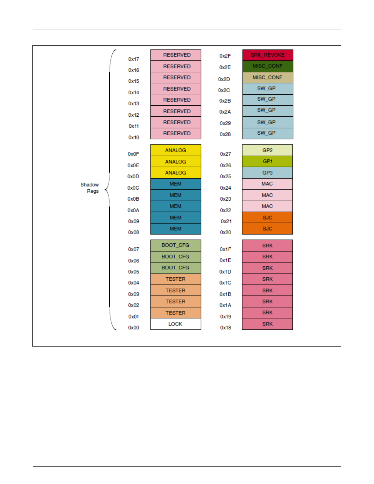
3.1 OCOTP (eFuse)
The OCOTP (On-Chip One-Time Programmable) memory, also named eFuse, is a special memory module in the chip. Any eFuse
bit in the field can be programmed from 0 to 1 just once (fused), but the read operation has no limitations. The memory space
contains the whole chip configuration. Here are some key configurations:
• Boot mode
• MAC address
• FlexRAM setting
For the eFuse programming examples using the Flashloader, see Program OCOTP (eFuse).
The eFuse memory space is not assigned to the system 4G address space, so the normal address Read/Write cannot be used
to access the eFuse registers. A specific process is needed to Read/Write the eFuse registers and for the Flashloader to support
this feature.
The OTP memory footprint in Figure 2 shows the registers grouped by the lock region.
i.MX RT Flashloader Use Case, Rev. 2, February 4, 2021
Application Note 3 / 23
i.MX RT1050 Processor Reference Manual
Page 4
NXP Semiconductors
i.MX RT1050 OCOTP and external flash
Figure 2. OTP memory footprint
3.2 External flash
The i.MX RT1050 device provides various external flash memory interfaces:
• 8/16-bit SLC NAND FLASH with the ECC handled by software
• SD/eMMC
• HyperFlash
• Parallel NOR FLASH with XIP support
• Single/dual-channel quad SPI FLASH with XIP support
i.MX RT Flashloader Use Case, Rev. 2, February 4, 2021
Application Note 4 / 23
Page 5

NXP Semiconductors
i.MX RT1050 OCOTP and external flash
The external flash can be used to store the application image and make the i.MX RT1050 boot from the flash image. The
Flashloader includes various flash-programming algorithms to support the flash image programming in the development and
manufacture phases.
3.2.1 Bootable image
For the i.MX RT1050 device, the application image must be stored in the external flash device. It is different for MCUs that have
an internal parallel NOR flash. The internal parallel NOR flash space is assigned to the system 4 G memory space and can be
accessed directly by address. The core can fetch the boot image binary directly and run the eXecute-In-Place (XIP).
After the chip power reset, the BootROM in the i.MX RT1050 always runs first. It checks the boot mode and helps the core to boot
from a specific external flash device.
For various flash interfaces and boot modes, the BootROM must get some additional information from the application image
in the external flash device. By combining the additional necessary information with the application image, you get the final
programmable bootable image.
The additional necessary information are:
• Flash Configuration Block (FCB):
— Optional (used for serial/parallel NOR FLASH).
— Offset: 0x0000.
— Description: The structure of the external flash interface definition.
• Image Vector Table (IVT):
— Required.
— Offset: 0x0400 (non-XIP flash)/0x1000 (XIP flash).
— Description: The structure includes the address information of the application binary, DCD, BD, and CSF.
• Boot Data (BD):
— Required.
— Offset: 0x0420 (non-XIP)/0x1020 (XIP).
— Description: The structure includes the start address and size of the SB image.
• Device Configuration Data (DCD):
— Optional.
— Offset: Defined in the IVT.
— Description: Currently used to configure the SDRAM (SEMC interface).
• Application binary:
— Required.
— Offset: 0x2000 (Typical).
— Description: The pure application binary.
• Command Sequence File (CSF):
— Optional.
— Offset: Defined in the IVT.
— Description: Used by the High-Assurance Boot (HAB).
• KeyBlob:
— Optional.
— Offset: Defined in the IVT.
i.MX RT Flashloader Use Case, Rev. 2, February 4, 2021
Application Note 5 / 23
Page 6
NXP Semiconductors
i.MX RT1050 OCOTP and external flash
— Description: Secure boot key information.
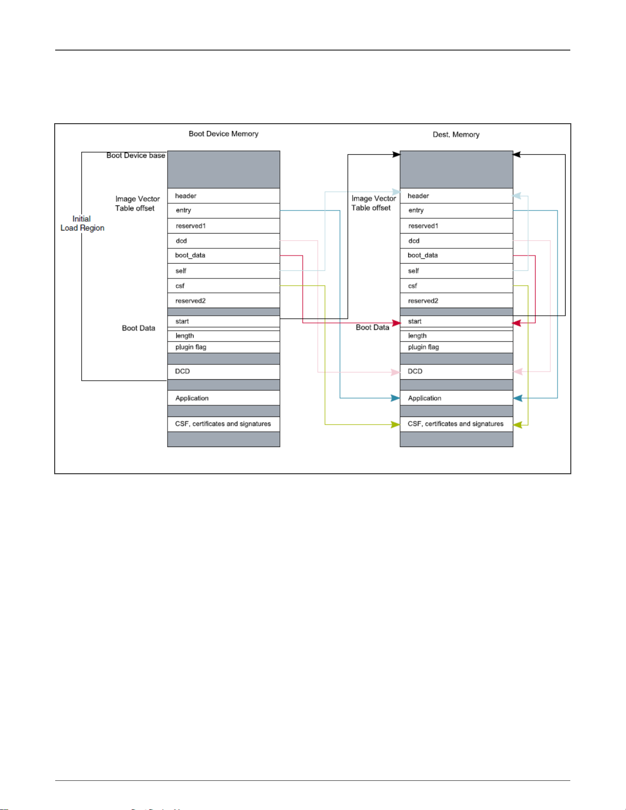
The elftosb tool in the Flashloader can be used to create the bootable image. The Flashloader also provides some BD example
files. Figure 3 shows the bootable image layout and the function of each block.
Figure 3. Bootable image layout
3.2.2 Booting from external flash
With BootROM, the i.MX RT1050 can boot from various external flash devices in the XIP (NOR-only) or NON-XIP modes. Based
on the IVT and BD information in the Bootable image, the BootROM starts up the application binary directly (XIP) or copies the
bootable image to the RAM and starts up the application binary (NON-XIP).
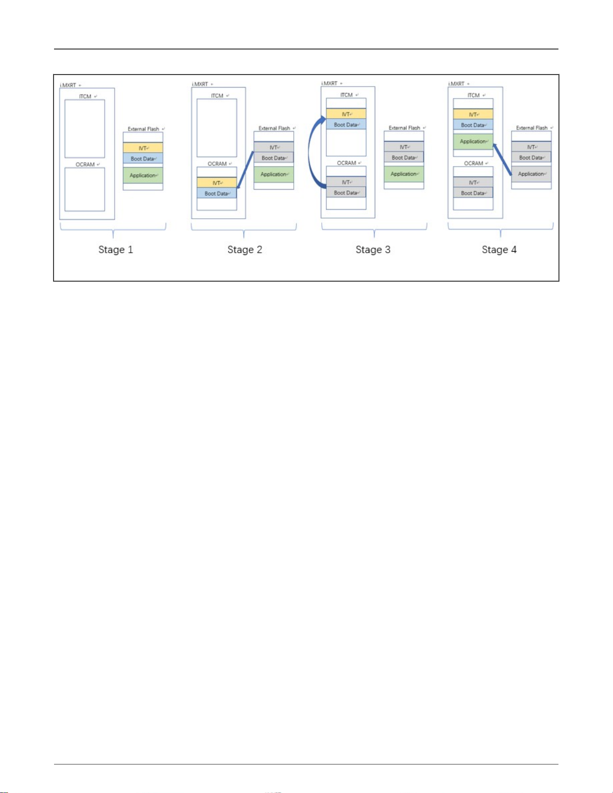
Figure 4 shows the process of the NON-XIP boot.
• Stage 1: Bootable image is in the external flash.
• Stage 2: BootROM loads the starting 4 KB of data from the bootable image to the internal SRAM (OCRAM). It includes the
IVT and BD information and will be used for the application image loading.
• Stage 3: BootROM transfers the starting 4 KB of data from the internal SRAM (OCRAM) to the destination address space
of the bootable image.
• Stage 4: BootROM continues loading the rest of the bootable image from the external flash to the destination address
space and starts up the application binary.
i.MX RT Flashloader Use Case, Rev. 2, February 4, 2021
Application Note 6 / 23
Page 7
NXP Semiconductors
i.MX RT1050 Flashloader use cases
Figure 4. NON-XIP boot
In stage 2, if the BootROM finds the destination address equal to the external flash address, it will skip the remaining stages and
start up the application binary directly in the flash address space. It is XIP boot.
4 i.MX RT1050 Flashloader use cases
This chapter describes the Flashloader usage case by case and provides the command lines and simple descriptions.
4.1 Target platform environment
All the Flashloader use cases are demonstrated using the MIMXRT1050 EVK target platform, as shown in Figure 5.
For the Flashloader usage, set the configurations as follows:
• Set the Boot Mode Switch (SW7) to 0001b for the serial downloader mode.
• BootROM/Flashloader supports both the OpenSDA/UART and USB-HID ports as the communication interfaces with the
PC host.
• Set the correct Power Supply Switch (J1) based on the communication interfaces used:
— OpenSDA/UART - J1-5&J1-6
— USB-HID - J1-3&J1-4
i.MX RT Flashloader Use Case, Rev. 2, February 4, 2021
Application Note 7 / 23
Page 8

NXP Semiconductors
i.MX RT1050 Flashloader use cases
Figure 5. MIMXRT1050 EVK
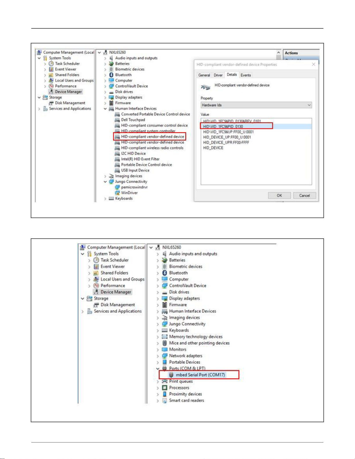
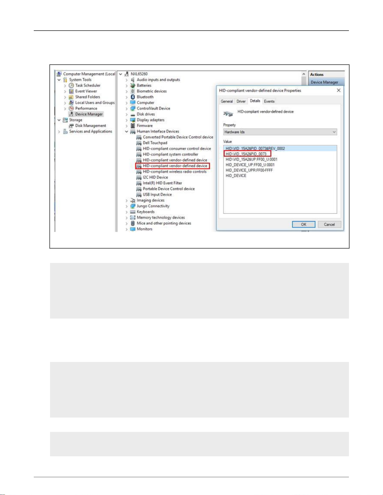
When you set the USB-HID as the communication interface with the host PC (Windows OS), the USB-HID device (as shown in
Figure 6) appears in the Windows OS Device Manager.
i.MX RT Flashloader Use Case, Rev. 2, February 4, 2021
Application Note 8 / 23
Page 9
NXP Semiconductors
i.MX RT1050 Flashloader use cases
Figure 6. MIMXRT1050 EVK board USB-HID device
When you set the UART as the communication interface with the host PC (Windows OS), the COM device (as shown in Figure
7) appears in the Windows OS Device Manager.
Figure 7. MIMXRT1050 EVK board UART device
i.MX RT Flashloader Use Case, Rev. 2, February 4, 2021
Application Note 9 / 23
Page 10

NXP Semiconductors
i.MX RT1050 Flashloader use cases
NOTE
The ROM detects the communication over the USB-HID or UART ports and the unused port will be disabled. The
board must be reset to change the communication port used to communicate with the host PC.
4.2 Serial Downloader mode
The BootROM provides the Serial Downloader feature via the UART or USB-HID interfaces, based on the Serial Downloader
Protocol. The main purpose of the Serial Download Protocol is to download bootable images (Flashloader) from the PC (SDPHost
tool) to the device’s internal RAM memory and execute the bootable images in the RAM space. There is a set of commands to read
and write a memory/register unit, get the status of the last command, jump, and execute the image from the provided address.
4.2.1 SDPHost downloads Flashloader image
The BootROM solidified into the i.MX RT chip does not support programming the flash device and the eFuse register. For the
two targets, the Flashloader image is downloaded to the i.MX RT internal RAM using SDPHost (communicates with the running
BootROM) and takes over the device from the BootROM (by the jump-address command of SDPHost). Then it implements the
program process (communicates with the blhost tool).
In addition, the SDPHost jump-address command can start up the image just with the IVT header. Therefore, the
ivt_flashloader.bin
1. Set the MIMXRT1050 EVK board to the Serial Downloader mode and connect the UART/USB-HID interface to the host
PC.
image should be used here.
2. Open the Windows OS Command Prompt and change the directory to
Flashloader_i.MXRT1050_GA\Flashloader_RT1050_1.1\Tools\sdphost\win
.
3. Verify that the SPDHost tool communicates with the BootROM of MIMXRT1050-EVK.
• Using UART interface:
>sdphost.exe -p COM17 -- error-status
Status (HAB mode) = 1450735702 (0x56787856) HAB disabled.
Reponse Status = 4042322160 (0xf0f0f0f0) HAB Success.
• Using USB-HID interface:
>sdphost.exe -u 0x1fc9,0x0130 -- error-status
Status (HAB mode) = 1450735702 (0x56787856) HAB disabled.
Reponse Status = 4042322160 (0xf0f0f0f0) HAB Success.
NOTE
-p COM17 and -u 0x1fc9,0x0130 are used to indicate the COM and USB-HID port. The value of COM17 and
0x1fc9,0x0130 can be obtained in Target platform environment. For the USB-HID interface, the PID and VID values
can also be omitted in the command. The following cases only show the commands using the USB-HID interface.
4. Download the IVT Flashloader image onto the MIMXRT1050-EVK board.
>sdphost.exe -u 0x1fc9,0x0130 -- write-file 0x20000000 "..\..\Mfgtools-rel\Profiles\MXRT105X\OS
Firmware\ivt_flashloader.bin"
Preparing to send 90039 (0x15fb7) bytes to the target.
(1/1)1%Status (HAB mode) = 1450735702 (0x56787856) HAB disabled.
Reponse Status = 2290649224 (0x88888888) Write File complete.
5. Start up the Flashloader image.
>sdphost.exe -u 0x1fc9,0x0130 -- jump-address 0x20000400
Status (HAB mode) = 1450735702 (0x56787856) HAB disabled.
i.MX RT Flashloader Use Case, Rev. 2, February 4, 2021
Application Note 10 / 23
Page 11
NXP Semiconductors
i.MX RT1050 Flashloader use cases
The USB-HID is re-enumerated by the running Flashloader image. The communication through the USB-HID changes from
the BootROM to the Flashloader running in the internal RAM.
Figure 8. Re-enumerated USB-HID device
6. Verify the communication with a running Flashloader using the blhost tool.
# change the directory to
“Flashloader_i.MXRT1050_GA\Flashloader_RT1050_1.1\Tools\blhost\win”
>blhost.exe -u -- get-property 1
Inject command 'get-property'
Response status = 0 (0x0) Success.
Response word 1 = 1258422528 (0x4b020100)
Current Version = K2.1.0
4.3 Program OCOTP (eFuse)
1. Download and start up the Flashloader image, as shown in SDPHost downloads Flashloader image.
2. Verify that the blhost tool communicates with the Flashloader running on the MIMXRT1050-EVK board.
# change the directory to
“Flashloader_i.MXRT1050_GA\Flashloader_RT1050_1.1\Tools\blhost\win”
>blhost.exe -u 0x15a2,0x0073 -- get-property 1
Inject command 'get-property'
Response status = 0 (0x0) Success.
Response word 1 = 1258422528 (0x4b020100)
Current Version = K2.1.0
3. Show the blhost help information about the eFuse operations commands.
>blhost.exe -?
……
Command:
i.MX RT Flashloader Use Case, Rev. 2, February 4, 2021
Application Note 11 / 23
Page 12

NXP Semiconductors
……
efuse-program-once <addr> <data>
Program one word of OCOTP Field
<addr> is ADDR of OTP word, not the shadowed memory address.
<data> is hex digits without prefix '0x' efuse-read-once <addr>
Read one word of OCOTP Field <addr> is ADDR of OTP word, not
the shadowed memory address.
4. Program the eFuse register SRK_REVOKE as an example.
• SRK_REVOKE eFuse OCOTP index: 0x2F.
• SRK_REVOKE eFuse shadow register address: 0x401F46F0.
• Program the SRK_REVOKE eFuse LSB to: 0x5A.
• Program the SRK_REVOKE eFuse MSB to: 0xFE.
• Verify the SRK_REVOKE eFuse via a shadow register.
>blhost.exe -u 0x15a2,0x0073 -- efuse-program-once 0x2F 0000005A
Inject command 'efuse-program-once'
Successful generic response to command 'efuse-program-once'
Response status = 0 (0x0) Success.
>blhost.exe -u 0x15a2,0x0073 -- efuse-program-once 0x2F FE000000
Inject command 'efuse-program-once'
Successful generic response to command 'efuse-program-once'
Response status = 0 (0x0) Success.
>blhost.exe -u 0x15a2,0x0073 -- efuse-read-once 0x2F
Inject command 'efuse-read-once'
Response status = 0 (0x0) Success.
Response word 1 = 4 (0x4)
i.MX RT1050 Flashloader use cases
5. Verify the shadow register of the SRK_REVOKE eFuse.
>blhost.exe -u 0x15a2,0x0073 -- read-memory 0x401F46F0 4
Inject command 'read-memory'
Successful response to command 'read-memory' 5a 00 00 fe (1/1)100% Completed!
Successful generic response to command 'read-memory'
Response status = 0 (0x0) Success.
Response word 1 = 4 (0x4)
Read 4 of 4 bytes.
6. Some key points.
• The eFuse bits can only be programmed from 0 to 1. The OCOTP ignores the writes changing from 1 to 0. For one
eFuse register, the efuse-program-once command can be implemented for a specific bit field in multiple steps.
• The efuse-program-once command includes the eFuse register reload command by default. The latest eFuse
register value can be obtained from a shadow register after the efuse-program-once command.
4.3.1 Program boot mode eFuse to SD boot
• BOOT_CFG eFuse OCOTP index: 0x05.
• BOOT_CFG eFuse OCOTP index: 0x06.
• BOOT_CFG (0x05) eFuse shadow register address: 0x401F4450.
• BOOT_CFG (0x06) eFuse shadow register address: 0x401F4460.
• Program the BOOT_CFG (0x06) eFuse to: 0x00000010.
i.MX RT Flashloader Use Case, Rev. 2, February 4, 2021
Application Note 12 / 23
Page 13

NXP Semiconductors
• Program the BOOT_CFG (0x05) eFuse to: 0x00000040.
• Verify the eFuse registers via shadow registers.
First, implement Step 1 to Step 3 in Program OCOTP (eFuse).
>blhost.exe -u -- efuse-program-once 0x06 00000010
>blhost.exe -u -- efuse-program-once 0x05 00000040
>blhost.exe -u -- efuse-read-once 0x06
>blhost.exe -u -- efuse-read-once 0x05
>blhost.exe -u -- read-memory 0x401F4460 4
>blhost.exe -u -- read-memory 0x401F4450 4
4.3.2 Program FlexRAM eFuse
• MISC_CFG eFuse OCOTP index: 0x2D.
• MISC_CFG (0x2D) eFuse shadow register address: 0x401F46D0.
• Select the group 0011: DTCM 128 KB, ITCM 32 KB, ORAM 352 KB.
• Program the MISC_CFG (0x2D) eFuse to: 0x00030000.
• Verify the eFuse registers via shadow registers.
Table 2 shows the i.MX RT1050 FlexRAM RAM bank partition.
i.MX RT1050 Flashloader use cases
Table 2. i.MX RT1050 FlexRAM banks
Parameter DTCM ITCM ORAM
0000 128 KB 128 KB 256 KB
0001 128 KB 64 KB 320 KB
0010 128 KB 256 KB 128 KB
0011 128 KB 32 KB 352 KB
0100 64 KB 128 KB 320 KB
0101 64 KB 64 KB 384 KB
0110 64 KB 256 KB 192 KB
0111 0 KB 448 KB 64 KB
1000 256 KB 128 KB 128 KB
1001 256 KB 64 KB 192 KB
1010 192 KB 256 KB 64 KB
1011 448 KB 0 KB 64 KB
1100 0 KB 128 KB 384 KB
1101 32 KB 32 KB 448 KB
Table continues on the next page...
i.MX RT Flashloader Use Case, Rev. 2, February 4, 2021
Application Note 13 / 23
Page 14

NXP Semiconductors
i.MX RT1050 Flashloader use cases
Table 2. i.MX RT1050 FlexRAM banks (continued)
Parameter DTCM ITCM ORAM
1110 0 KB 256 KB 256 KB
1111 0 KB 0 KB 512 KB
First, implement Step 1 to Step 3 in Program OCOTP (eFuse).
>blhost.exe -u -- efuse-program-once 0x2D 00030000
>blhost.exe -u -- efuse-read-once 0x2D
>blhost.exe -u -- read-memory 0x401F46D0 4
4.4 Building the bootable image
The elftosb tool creates a binary output file that contains the application image along with a series of Flashloader commands. The
output file is known as an SB file. These files have a
Flashloader commands present in the output file. This command file is called a BD file.
.sb
extension. The tool uses an input command file to control a sequence of
The XIP
hello_world
1. Build the XIP
2. Copy
project for the QSPI NOR flash is used to demonstrate the process of creating a bootable image.
hello_world.out
hello_world.out
to the
file with XIP_BOOT_HEADER_ENABLE=0 and XIP_BOOT_HEADER_DCD_ENABLE=0.
elftosb/win
directory.
Figure 9. Copying
hello_world.out
to
elftosb
3. Open the Windows OS Command Prompt and change the directory
to
Flashloader_i.MXRT1050_GA\Flashloader_RT1050_1.1\Tools\elftosb\win
>elftosb.exe -f imx -V -c ..\..\bd_file\imx10xx\imx-flexspinor-normal-unsigned.bd -o
ivt_flexspi_nor_hello_world.bin hello_world.out
.
There are two bootable images with the IVT information after the above command:
i.MX RT Flashloader Use Case, Rev. 2, February 4, 2021
Application Note 14 / 23
Page 15
NXP Semiconductors
•
ivt_flexspi_nor_hello_world.bin
i.MX RT1050 Flashloader use cases
The region from 0 to
•
ivt_flexspi_nor_hello_world_nopadding.bin
No padding bytes before ivt_offset.
The later one (
The command may crash if the input file (
macros XIP_BOOT_HEADER_ENABLE=0 and XIP_BOOT_HEADER_DCD_ENABLE=0 are set when building
the
.out
file.
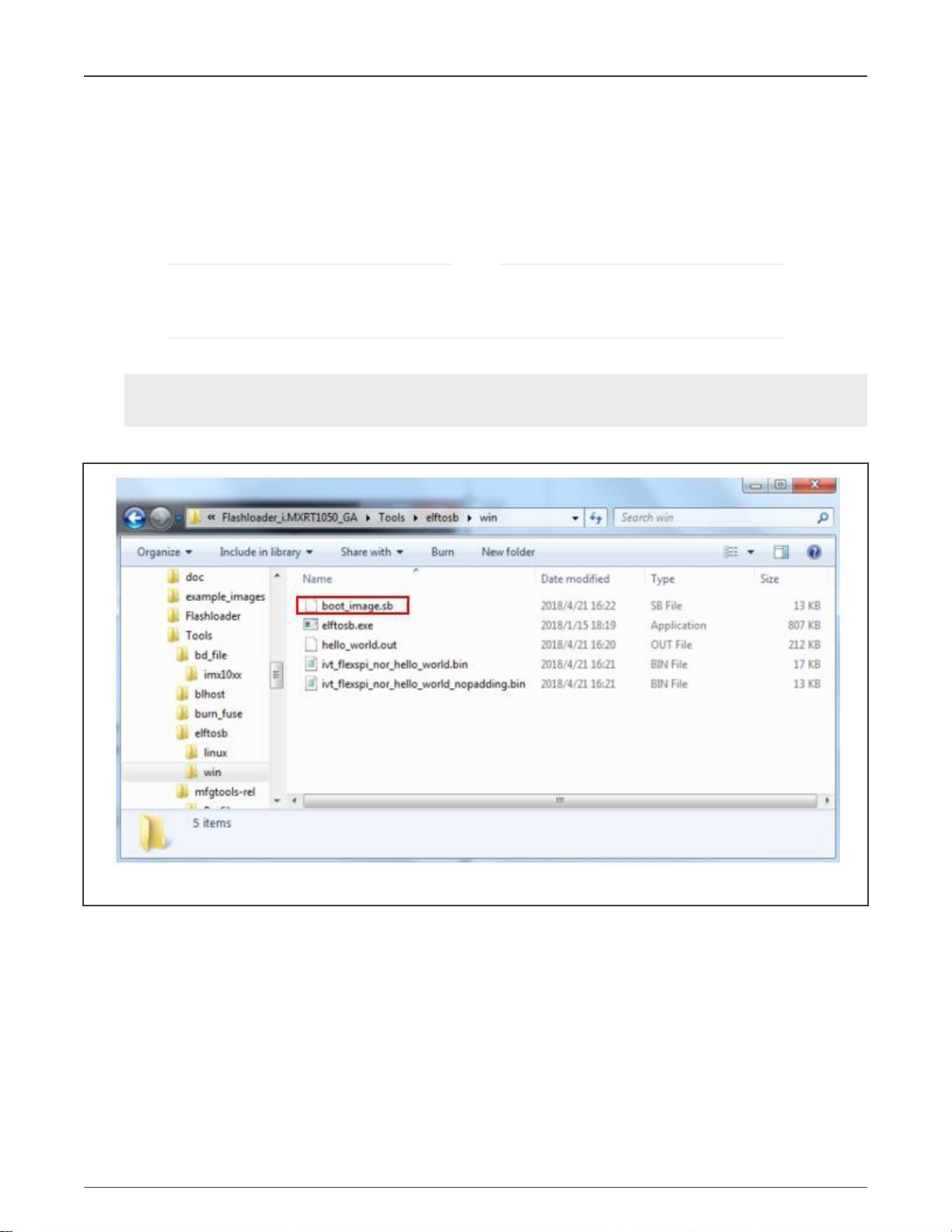
4. Create the final SB image.
>elftosb.exe -f kinetis -V -c ..\..\bd_file\imx10xx\program_flexspinor_image_qspinor.bd -o
boot_image.sb ivt_flexspi_nor_hello_world_nopadding.bin
boot_image.sb
The
file is now in the
ivt_offset
nopadding.bin
elftosb\win
is filled with padding bytes (all 0x00).
) is used to generate the SB file for the QSPI NOR flash.
NOTE
.out
) includes the boot header sections. Make sure the
directory.
Figure 10. Creating
boot_image.sb
4.5 Programming external flash device
For the flash programming, the Flashloader provides an easy-to-use GUI programming tool (Mfgtool).
4.5.1 Mfgtool
The Mfgtool is a GUI tool that helps to program the external flash. It integrates the functionalities of the SDPHost and blhost tools
and can detect an i.MX MCU BootROM connected to the PC host.
These steps show how to program the SB image from Building the bootable image using the Mfgtool.
1. Copy the
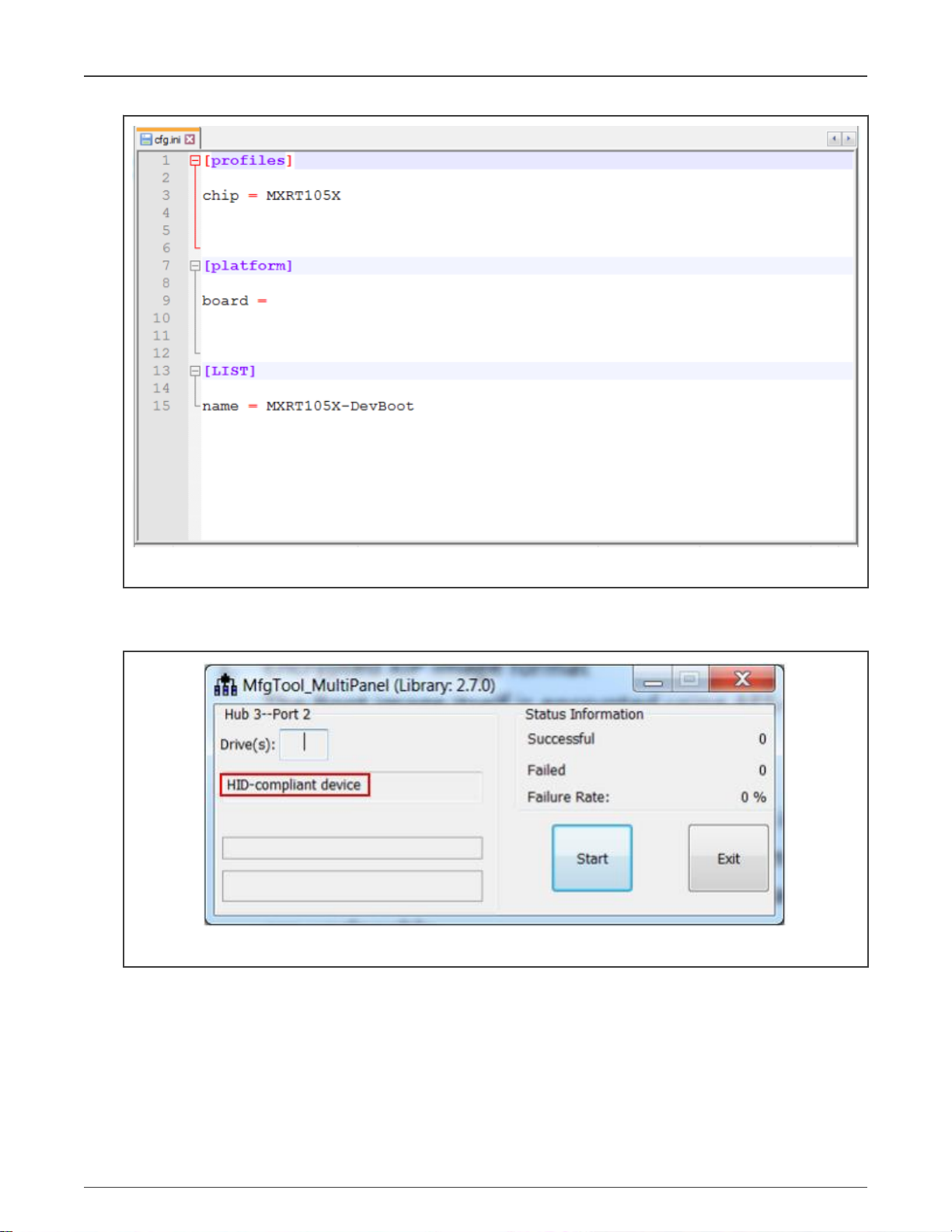
2. Change the name under [List] to MXRT105x-DevBoot in the
Application Note 15 / 23
boot_image.sb
file to the
<Mfgtool_root_dir>\Profiles\MXRT105X\OS
cfg.ini
file in the
i.MX RT Flashloader Use Case, Rev. 2, February 4, 2021
Firmware folder.
<Mfgtool_root_dir>
directory.
Page 16
NXP Semiconductors
i.MX RT1050 Flashloader use cases
Figure 11. Setting the name of the LIST item
3. Set the MIMXRT1050-EVK board to the Serial Downloader mode and connect the USB-HID interface to the host PC.
4. Open the Mfgtool and connect to the MIMXRT1050-EVK board.
Figure 12. Connect with MIMXRT1050 EVK
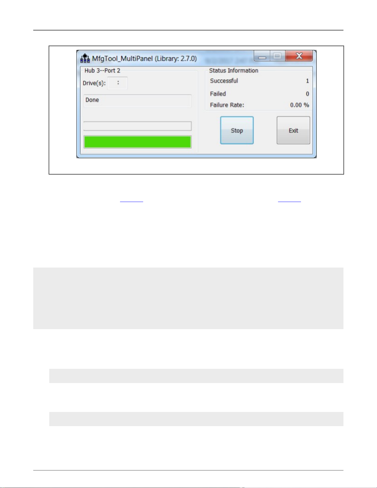
5. Program the bootable image. Click the Start button to trigger a programming sequence and wait for it to complete, as shown
in Figure 13. To exit Mfgtool, click the Stop and Exit buttons.
i.MX RT Flashloader Use Case, Rev. 2, February 4, 2021
Application Note 16 / 23
Page 17
NXP Semiconductors
i.MX RT1050 Flashloader use cases
Figure 13. Programing the flash successfully
6. Switch the MIMXRT1050-EVK board to a correct boot mode for the programmed SB image and verify the application.
For more information about building the bootable image and programming the external flash, see
SPI Flash and SD Card
(document AN12107) and
How to Enable Boot from QSPI Flash
How to Enable Boot from Octal
(document AN12108).
4.5.2 blhost
The blhost application is a command-line utility used on the host computer to initiate communication and issue commands to
the MCU bootloader (Flashloader). The application only sends one command per invocation. It can communicate directly with the
Flashloader over the host computer UART (Serial Port) or USB connections and then implement the programming of the external
flash device. It is also available under the Downloads tab at MCUBOOT.
Example programming SB file via USB connection.
>blhost.exe -u -- receive-sb-file boot_image.sb
Inject command 'receive-sb-file'
Preparing to send 22208 (0x56c0) bytes to the target.
Successful generic response to command 'receive-sb-file'
(1/1)100% Completed!
Successful generic response to command 'receive-sb-file'
Response status = 0 (0x0) Success.
Wrote 22208 of 22208 bytes.
The blhost can also support to program the binary (not SB file) step by step.
1. The config parameter should be stored in RAM, which will be used in configuring the FlexSPI in next step. The config
parameter is selected according to the FLASH type. Different NOR flash need different config parameters to enable and
program. For more information, see FlexSPI configuration options and memory ID.
>blhost.exe -u -- fill-memory 0x2000 0x4 0xC0000006
2. Use the config parameter stored in RAM in previous step to config the FlexSPI. Then, you can read, erase, and program
the flash. The value 0x9 in the command line indicates the memory ID. For more information, see FlexSPI configuration
options and memory ID.
>blhost.exe -u -- configure-memory 0x9 0x2000
i.MX RT Flashloader Use Case, Rev. 2, February 4, 2021
Application Note 17 / 23
Page 18
NXP Semiconductors
i.MX RT10xx Flashloader
3. Program the raw binary using -- flash-erase-region and -- write-memory commands, or program the formatted image
using -- flash-image by memory ID.
>blhost.exe -u -- flash-image hello_world.hex erase 0x9
5 i.MX RT10xx Flashloader
This chapter provide more Flashloader information of other RT10xx platforms.
5.1 Obtain Flashloader packages
• i.MX RT1010
There is no standalone Flashloader package for i.MX RT1010. Please obtain the SDK including the mcu-boot middleware
and find the Flashloader elements in
• i.MX RT1015
There is no standalone Flashloader package for i.MX RT1015. Please obtain the SDK including the mcu-boot middleware
and find the Flashloader elements in
• i.MX RT1020
Please find the Flashloader package on i.MX RT1020 Crossover MCU with Arm® Cortex®-M7 core
<SDK ROOT>\middleware\mcu-boot
<SDK ROOT>\middleware\mcu-boot
.
.
• i.MX RT1050
Please find the Flashloader package on i.MX RT1050 Crossover MCU with Arm® Cortex®-M7 core
• i.MX RT1060
Please find the Flashloader package on i.MX RT1060 Crossover MCU with Arm® Cortex®-M7 core
NOTE
For RT1020, RT1050 and RT1060, the latest SDKs also include Flashloader elements in
ROOT>\middleware\mcu-boot
of SDK may not have the mcu-boot module.
if selecting the mcu-boot module in SDK builder page. But the older version
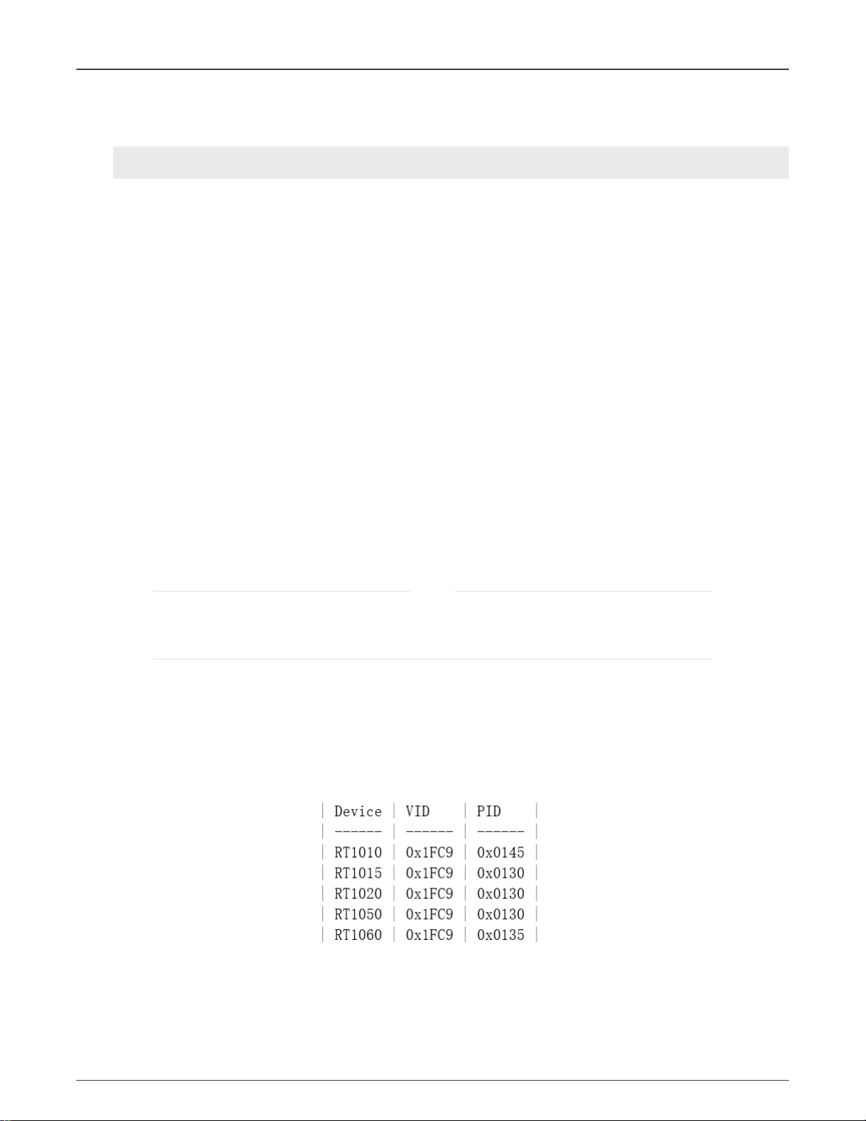
5.2 Serial downloader
The
sdphost.exe
<SDK ROOT>\middleware\mcu-boot\bin\Tools\sdphost\win\sdphost.exe
And the USB VID/PID for different i.MX RT10xx platform can be found in the list:
can also be found in the SDK:
<SDK
Likewise, the
ivt_flashloader.bin
binary can also be found in the SDK:
<SDK ROOT>\middleware\mcu-boot\bin\Tools\mfgtools-rel\Profiles\<Device Family>\OS Firmware\ivt_flashloader.bin
i.MX RT Flashloader Use Case, Rev. 2, February 4, 2021
Application Note 18 / 23
Page 19

NXP Semiconductors
i.MX RT10xx Flashloader
ivt_flashloader.bin
load address and jump address can be derived by decoding the ivt header of the
ivt_flashloader.bin
file from
the SDK. The ivt header is typically located at offset 0x000 or 0x400 and the first word is 0x402000d1. The jump address is at
offset 0x14 from the start of the ivt header. The load address for the spdhost write-file command is the jump address minus any
padding in the binary file before ivt header (0x000 or 0x400). The jump address is the address that needs to be used for the
spdhost jump-address command.
shows an example from i.MX RT1060
ivt_flashloader.bin
binary.
• ivt first word 0x402000d1 is at 0x00000400.
• The jump address is 0x20000400 at ivt head offset 0x14.
• The load address is 0x20000400 – 0x00000400 = 0x20000000.
Figure 14. Example from i.MX RT1060 ivt_flashloader.bin binary
And the load address/jump address for different i.MX RT10xx platform can be found in the list:
Example loading flashloader from SDK for RT1010:
>sdphost.exe -u 0x1fc9,0x0145 -V -- write-file 0x20205800 "<path to flashloader>\ivt_flashloader.bin"
>sdphost.exe -u 0x1fc9,0x0145 -V -- jump-address 0x20205800
RT1010 example of complete steps are:
1. Power down RT1010 and switch to Serial Downloader Boot mode:
BOOT_MODE[1:0]=01
2. Power up RT1010 and connect USB cable.
3. Load flashloader binary into RAM and launch it using sdphost.
>sdphost.exe -u 0x1fc9,0x0145 -V -- write-file 0x20205800 ".\ivt_flashloader.bin"
>sdphost.exe -u 0x1fc9,0x0145 -V -- jump-address 0x20205800
i.MX RT Flashloader Use Case, Rev. 2, February 4, 2021
Application Note 19 / 23
Page 20

NXP Semiconductors
Conclusion
4. Set FlexSPI configuration options. Configure FlexSPI and program image to flash with blhost.
>blhost.exe -u 0x15a2,0x0073 -- fill-memory 0x2000 4 0xC0000007
>blhost.exe -u 0x15a2,0x0073 -- configure-memory 9 0x2000
>blhost.exe -u 0x15a2,0x0073 -- flash-image .\imxrt1010_evk-firmware.hex erase 9
5. Power down RT1010 and switch to Internal Boot mode.
BOOT_MODE[1:0]=10
6. Power on RT1010.
6 Conclusion
This application note describes the background knowledge of the Flashloader and the use cases of the Flashloader. For more
information, see these documents:
•
i.MX MCU Manufacturing User's Guide.pdf
•
Kinetis blhost User's Guide.pdf
•
Kinetis SDPHost User's Guide.pdf
•
MCUX Flashloader Reference Manual.pdf
7 Revision history
Table 3. Revision history
Revision number Date Substantive changes
0 08/2018 Initial release.
1 09/2018 Fixed errors in Program FlexRAM eFuse.
2 02/2021 Added blhost, and FlexSPI configuration options and memory ID.
A FlexSPI configuration options and memory ID
The source code for the flashloader is provided as an example in the SDK:
<SDK ROOT>\boards\<Board Name>\bootloader_examples\flashloader
The FlexSPI configuration options used by the blhost configure-memory command get passed to and
are defined by the flexspi_nor_get_config function in
Family>\src\flexspi_nor_flash_<Device Family>.c
The structure for serial_nor_config_option_t is specified in
boot\src\drivers\flexspi_nor\flexspi_nor_flash.h
/*
* Serial NOR Configuration Option
*/
typedef struct _serial_nor_config_option
{
union
{
struct
{
.
along with some enumerations for the option tag and device types.
<SDK ROOT>\middleware\mcu-boot\targets\<Device
<SDK ROOT>\middleware\mcu-
i.MX RT Flashloader Use Case, Rev. 2, February 4, 2021
Application Note 20 / 23
Page 21

NXP Semiconductors
FlexSPI configuration options and memory ID
uint32_t max_freq : 4; //!< Maximum supported Frequency
uint32_t misc_mode : 4; //!< miscellaneous mode
uint32_t quad_mode_setting : 4; //!< Quad mode setting
uint32_t cmd_pads : 4; //!< Command pads
uint32_t query_pads : 4; //!< SFDP read pads
uint32_t device_type : 4; //!< Device type
uint32_t option_size : 4; //!< Option size, in terms of uint32_t, size =
(option_size + 1) * 4
uint32_t tag : 4; //!< Tag, must be 0x0E
} B;
uint32_t U;
} option0;
union
{
struct
{
uint32_t dummy_cycles : 8; //!< Dummy cycles before read
uint32_t status_override : 8; //!< Override status register value during device mode
configuration
uint32_t pinmux_group : 4; //!< The pinmux group selection
uint32_t dqs_pinmux_group : 4; //!< The DQS Pinmux Group Selection
uint32_t drive_strength : 4; //!< The Drive Strength of FlexSPI Pads
uint32_t flash_connection : 4; //!< Flash connection option: 0 - Single Flash connected
to port A, 1 -
//! Parallel mode, 2 - Single Flash connected to Port B
} B;
uint32_t U;
} option1;
} serial_nor_config_option_t;
enum
{
kSerialNorCfgOption_Tag = 0x0c,
kSerialNorCfgOption_DeviceType_ReadSFDP_SDR = 0,
kSerialNorCfgOption_DeviceType_ReadSFDP_DDR = 1,
kSerialNorCfgOption_DeviceType_HyperFLASH1V8 = 2,
kSerialNorCfgOption_DeviceType_HyperFLASH3V0 = 3,
kSerialNorCfgOption_DeviceType_MacronixOctalDDR = 4,
kSerialNorCfgOption_DeviceType_MacronixOctalSDR = 5,
kSerialNorCfgOption_DeviceType_MicronOctalDDR = 6,
kSerialNorCfgOption_DeviceType_MicronOctalSDR = 7,
kSerialNorCfgOption_DeviceType_AdestoOctalDDR = 8,
kSerialNorCfgOption_DeviceType_AdestoOctalSDR = 9,
};
In most cases, you should be able to use 0xC000000n, where n is the serial clock frequency from the list of
kFlexSpiSerialClk_xxx values in
//! @brief FlexSPI supported speed defintions
enum
{
kFlexSpiSerialClk_30MHz = 1,
kFlexSpiSerialClk_50MHz = 2,
kFlexSpiSerialClk_60MHz = 3,
kFlexSpiSerialClk_75MHz = 4,
kFlexSpiSerialClk_80MHz = 5,
kFlexSpiSerialClk_100MHz = 6,
<SDK ROOT>\middleware\mcu-boot\targets\<Device Family>\src\target_config.h
.
i.MX RT Flashloader Use Case, Rev. 2, February 4, 2021
Application Note 21 / 23
Page 22

NXP Semiconductors
kFlexSpiSerialClk_133MHz = 7,
kFlexSpiSerialClk_166MHz = 8,
kFlexSpiSerialClk_200MHz = 9,
};
Table 4 shows the memory ID definitions for -- configure-memory command.
Table 4. Memory ID definitions for -- configure-memory command
Internal memory Device internal memory space
0 Internal memory (Default selected mmory)
16 (0 × 10) Execute-only region on internal flash (only used for flash-erase-all)
The memories that are remapped to internal space, and must be accessed by internal
Mapped external memory
addresses. (IDs in this group are only used for flash-erase-all and configure-memory,
and ignored by write-memory, read-memory, flash-erase-region and flash-image (use
default 0))
1 QuadSPI memory
8 SEMC NOR memory
9 FlexSPI NOR memory
FlexSPI configuration options and memory ID
10 (0xa) SPIFI NOR memory
Memories which cannot be remapped to internal spance, and only can be accessed
Unmapped external memory
by memories' addresses. (Must be spencified for all commends with <memoryID>
argument)
256 (0 × 100) SEMC NAND memory
257 (0 × 101) SPI NAND memory
272 (0 × 110) SPI NOR/EEPROM memory
273 (0 × 111) I2C NOR/EEPROM memory
288 (0 × 120) uSDHC SD memory
289 (0 × 121) uSDHC MMC memory
i.MX RT Flashloader Use Case, Rev. 2, February 4, 2021
Application Note 22 / 23
Page 23

How To Reach Us
Home Page:
nxp.com
Web Support:
nxp.com/support
Information in this document is provided solely to enable system and software implementers to use NXP products. There
are no express or implied copyright licenses granted hereunder to design or fabricate any integrated circuits based on the
information in this document. NXP reserves the right to make changes without further notice to any products herein.
NXP makes no warranty, representation, or guarantee regarding the suitability of its products for any particular purpose, nor
does NXP assume any liability arising out of the application or use of any product or circuit, and specifically disclaims any
and all liability, including without limitation consequential or incidental damages. “Typical” parameters that may be provided
in NXP data sheets and/or specifications can and do vary in different applications, and actual performance may vary over
time. All operating parameters, including “typicals,” must be validated for each customer application by customer's technical
experts. NXP does not convey any license under its patent rights nor the rights of others. NXP sells products pursuant to
standard terms and conditions of sale, which can be found at the following address: nxp.com/SalesTermsandConditions.
Right to make changes - NXP Semiconductors reserves the right to make changes to information published in this
document, including without limitation specifications and product descriptions, at any time and without notice. This
document supersedes and replaces all information supplied prior to the publication hereof.
Security — Customer understands that all NXP products may be subject to unidentified or documented vulnerabilities.
Customer is responsible for the design and operation of its applications and products throughout their lifecycles to reduce
the effect of these vulnerabilities on customer’s applications and products. Customer’s responsibility also extends to other
open and/or proprietary technologies supported by NXP products for use in customer’s applications. NXP accepts no
liability for any vulnerability. Customer should regularly check security updates from NXP and follow up appropriately.
Customer shall select products with security features that best meet rules, regulations, and standards of the intended
application and make the ultimate design decisions regarding its products and is solely responsible for compliance with all
legal, regulatory, and security related requirements concerning its products, regardless of any information or support that
may be provided by NXP. NXP has a Product Security Incident Response Team (PSIRT) (reachable at PSIRT@nxp.com)
that manages the investigation, reporting, and solution release to security vulnerabilities of NXP products.
NXP, the NXP logo, NXP SECURE CONNECTIONS FOR A SMARTER WORLD, COOLFLUX,EMBRACE, GREENCHIP,
HITAG, ICODE, JCOP, LIFE, VIBES, MIFARE, MIFARE CLASSIC, MIFARE DESFire, MIFARE PLUS, MIFARE FLEX,
MANTIS, MIFARE ULTRALIGHT, MIFARE4MOBILE, MIGLO, NTAG, ROADLINK, SMARTLX, SMARTMX, STARPLUG,
TOPFET, TRENCHMOS, UCODE, Freescale, the Freescale logo, AltiVec, CodeWarrior, ColdFire, ColdFire+, the Energy
Efficient Solutions logo, Kinetis, Layerscape, MagniV, mobileGT, PEG, PowerQUICC, Processor Expert, QorIQ, QorIQ
Qonverge, SafeAssure, the SafeAssure logo, StarCore, Symphony, VortiQa, Vybrid, Airfast, BeeKit, BeeStack, CoreNet,
Flexis, MXC, Platform in a Package, QUICC Engine, Tower, TurboLink, EdgeScale, EdgeLock, eIQ, and Immersive3D are
trademarks of NXP B.V. All other product or service names are the property of their respective owners. AMBA, Arm, Arm7,
Arm7TDMI, Arm9, Arm11, Artisan, big.LITTLE, Cordio, CoreLink, CoreSight, Cortex, DesignStart, DynamIQ, Jazelle,
Keil, Mali, Mbed, Mbed Enabled, NEON, POP, RealView, SecurCore, Socrates, Thumb, TrustZone, ULINK, ULINK2,
ULINK-ME, ULINK-PLUS, ULINKpro, μVision, Versatile are trademarks or registered trademarks of Arm Limited (or its
subsidiaries) in the US and/or elsewhere. The related technology may be protected by any or all of patents, copyrights,
designs and trade secrets. All rights reserved. Oracle and Java are registered trademarks of Oracle and/or its affiliates. The
Power Architecture and Power.org word marks and the Power and Power.org logos and related marks are trademarks and
service marks licensed by Power.org.
©
NXP B.V. 2018-2021. All rights reserved.
For more information, please visit: http://www.nxp.com
For sales office addresses, please send an email to: salesaddresses@nxp.com
Date of release: February 4, 2021
Document identifier: AN12238
 Loading...