

Page 1

NXP Semiconductors Document identifier: IMXLUG
User's Guide Rev. LF5.10.9_1.0.0, 31 March 2021
i.MX Linux® User's Guide
Page 2

NXP Semiconductors
Contents
Chapter 1 Overview............................................................................................... 6
1.1 Audience....................................................................................................................................6
1.2 Conventions...............................................................................................................................6
1.3 Supported hardware SoCs and boards..................................................................................... 6
1.4 References................................................................................................................................ 7
Chapter 2 Introduction........................................................................................... 9
Chapter 3 Basic Terminal Setup.......................................................................... 10
Chapter 4 Booting Linux OS................................................................................ 11
4.1 Software overview................................................................................................................... 11
4.1.1 Bootloader.................................................................................................................................11
4.1.2 Linux kernel image and device tree.......................................................................................... 12
4.1.3 Root file system.........................................................................................................................12
4.2 Universal update utility............................................................................................................ 12
4.2.1 Downloading UUU.....................................................................................................................12
4.2.2 Using UUU................................................................................................................................ 12
4.3 Preparing an SD/MMC card to boot........................................................................................ 13
4.3.1 Preparing the card.....................................................................................................................14
4.3.2 Copying the full SD card image.................................................................................................14
4.3.3 Partitioning the SD/MMC card...................................................................................................15
4.3.4 Copying a bootloader image..................................................................................................... 15
4.3.5 Copying the kernel image and DTB file.....................................................................................16
4.3.6 Copying the root file system (rootfs)......................................................................................... 17
4.4 Downloading images .............................................................................................................. 17
4.4.1 Downloading images using U-Boot........................................................................................... 17
4.4.1.1 Flashing an Arm Cortex-M4 image on QuadSPI .........................................................................17
4.4.1.2 Downloading an image to MMC/SD.............................................................................................18
4.4.1.3 Using eMMC................................................................................................................................ 20
4.4.1.4 Flashing U-Boot on SPI-NOR from U-Boot..................................................................................23
4.4.1.5 Flashing U-Boot on Parallel NOR from U-Boot............................................................................24
4.4.2 Using an i.MX board as the host server to create a rootfs........................................................ 25
4.5 How to boot the i.MX boards................................................................................................... 28
4.5.1 Booting from an SD card in slot SD1........................................................................................ 28
4.5.2 Booting from an SD card in slot SD2........................................................................................ 29
4.5.3 Booting from an SD card in slot SD3........................................................................................ 30
4.5.4 Booting from an SD card in slot SD4........................................................................................ 30
4.5.5 Booting from eMMC.................................................................................................................. 31
4.5.6 Booting from SATA................................................................................................................... 32
4.5.7 Booting from NAND...................................................................................................................32
4.5.8 Booting from SPI-NOR..............................................................................................................33
4.5.9 Booting from EIM (Parallel) NOR ............................................................................................. 33
4.5.10 Booting from QuadSPI or FlexSPI.......................................................................................... 33
4.5.11 Serial download mode for the Manufacturing Tool..................................................................35
4.5.12 How to build U-Boot and Kernel in standalone environment...................................................36
4.5.13 How to build imx-boot image by using imx-mkimage.............................................................. 38
4.6 Flash memory maps................................................................................................................40
i.MX Linux® User's Guide, Rev. LF5.10.9_1.0.0, 31 March 2021
User's Guide 2 / 103
Page 3

NXP Semiconductors
Contents
4.6.1 MMC/SD/SATA memory map................................................................................................... 40
4.6.2 NAND flash memory map......................................................................................................... 40
4.6.3 Parallel NOR flash memory map...............................................................................................40
4.6.4 SPI-NOR flash memory map.....................................................................................................41
4.6.5 QuadSPI flash memory map..................................................................................................... 41
4.7 Running Linux OS on the target.............................................................................................. 41
4.7.1 Running the image from NAND ................................................................................................43
4.7.2 Running Linux OS from Parallel NOR.......................................................................................44
4.7.3 Running the Linux OS image from QuadSPI ........................................................................... 44
4.7.4 Running the Arm Cortex-M4 image...........................................................................................44
4.7.5 Linux OS login...........................................................................................................................46
4.7.6 Running Linux OS from MMC/SD............................................................................................. 46
4.7.7 Running the Linux image from NFS.......................................................................................... 47
Chapter 5 Enabling Solo Emulation..................................................................... 48
Chapter 6 Power Management............................................................................ 49
6.1 Suspend and resume.............................................................................................................. 49
6.2 CPU frequency scaling............................................................................................................49
6.3 Bus frequency scaling............................................................................................................. 50
Chapter 7 Multimedia...........................................................................................52
7.1 i.MX multimedia packages.......................................................................................................52
7.2 Building limited access packages............................................................................................52
7.3 Multimedia use cases..............................................................................................................52
7.3.1 Playback use cases.................................................................................................................. 52
7.3.1.1 Audio-only playback.....................................................................................................................53
7.3.1.2 Video-only playback.....................................................................................................................53
7.3.1.3 Audio/Video file playback.............................................................................................................53
7.3.1.4 Multichannel audio playback........................................................................................................54
7.3.1.5 Other methods for playback.........................................................................................................54
7.3.1.6 Video playback to multiple displays............................................................................................. 54
7.3.2 Audio encoding......................................................................................................................... 55
7.3.3 Video encoding......................................................................................................................... 55
7.3.4 Transcoding.............................................................................................................................. 56
7.3.5 Audio recording......................................................................................................................... 56
7.3.6 Video recording......................................................................................................................... 57
7.3.7 Audio/Video recording...............................................................................................................58
7.3.8 Camera preview........................................................................................................................ 58
7.3.9 Recording the TV-in source...................................................................................................... 58
7.3.10 Web camera............................................................................................................................58
7.3.11 HTTP streaming...................................................................................................................... 59
7.3.12 HTTP live streaming................................................................................................................59
7.3.13 Real Time Streaming Protocol (RTSP) playback.................................................................... 59
7.3.14 RTP/UDP MPEGTS streaming............................................................................................... 60
7.3.15 RTSP streaming server...........................................................................................................61
7.3.16 Video conversion ....................................................................................................................62
7.3.17 Video composition...................................................................................................................62
7.4 PulseAudio input/output settings............................................................................................. 63
7.5 Installing gstreamer1.0-libav into rootfs...................................................................................65
i.MX Linux® User's Guide, Rev. LF5.10.9_1.0.0, 31 March 2021
User's Guide 3 / 103
Page 4

NXP Semiconductors
Contents
Chapter 8 Audio................................................................................................... 66
8.1 DSP support............................................................................................................................ 66
8.1.1 HiFi 4 DSP framework...............................................................................................................66
8.1.2 Sound Open Firmware.............................................................................................................. 66
Chapter 9 Graphics..............................................................................................67
9.1 imx-gpu-sdk.............................................................................................................................67
9.2 G2D-imx-samples....................................................................................................................67
9.3 viv_samples.............................................................................................................................68
9.4 Qt 5..........................................................................................................................................69
Chapter 10 Security............................................................................................. 70
10.1 CAAM kernel driver............................................................................................................... 70
10.1.1 Introduction............................................................................................................................. 70
10.1.2 Source files............................................................................................................................. 71
10.1.3 Module loading........................................................................................................................72
10.1.4 Kernel configuration................................................................................................................ 72
10.1.5 How to test the drivers............................................................................................................ 73
10.2 Crypto algorithms support..................................................................................................... 75
10.3 CAAM Job Ring backend driver specifications......................................................................76
10.3.1 Verifying driver operation and correctness..............................................................................77
10.3.2 Incrementing IRQs in /proc/interrupts..................................................................................... 77
10.3.3 Verifying the 'self test' fields say 'passed' in /proc/crypto........................................................77
10.4 OpenSSL offload................................................................................................................... 78
10.4.1 OpenSSL software architecture.............................................................................................. 78
10.4.2 OpenSSL's ENGINE interface.................................................................................................79
10.4.3 NXP solution for OpenSSL hardware offloading..................................................................... 80
10.4.4 Deploying OpenSSL into rootfs...............................................................................................80
10.4.5 Running OpenSSL benchmarking tests.................................................................................. 80
10.4.5.1 Running OpenSSL benchmarking tests for symmetric ciphering and digest............................. 80
10.4.5.2 Running OpenSSL speed for Asymmetric ciphers.....................................................................81
10.5 Disk encryption acceleration..................................................................................................81
10.5.1 Enabling disk encryption support in kernel..............................................................................82
10.5.2 User space tools for disk encryption....................................................................................... 83
10.5.3 DM-Crypt using CAAM's tagged key.......................................................................................83
10.5.4 Usage......................................................................................................................................85
Chapter 11 Connectivity.......................................................................................90
11.1 Connectivity for Bluetooth wireless technology and Wi-Fi ....................................................90
11.2 Connectivity for USB type-C..................................................................................................91
11.3 NXP Bluetooth/Wi-Fi information...........................................................................................92
11.4 Certification............................................................................................................................93
11.4.1 WFA certification..................................................................................................................... 93
11.4.2 Bluetooth controller certification.............................................................................................. 93
11.5 Wi-Fi throughput....................................................................................................................93
11.5.1 Throughput test setup............................................................................................................. 93
Chapter 12 Virtualization......................................................................................94
12.1 Xen overview.........................................................................................................................94
12.2 Basic architecture..................................................................................................................94
12.3 Xen xl.....................................................................................................................................94
i.MX Linux® User's Guide, Rev. LF5.10.9_1.0.0, 31 March 2021
User's Guide 4 / 103
Page 5

NXP Semiconductors
Contents
12.4 How to boot multiple operating systems on i.MX 8QuadMax EVK........................................94
12.5 Jailhouse hypervisor..............................................................................................................98
Chapter 13 NXP eIQ Machine Learning............................................................ 101
Chapter 14 Revision History.............................................................................. 102
i.MX Linux® User's Guide, Rev. LF5.10.9_1.0.0, 31 March 2021
User's Guide 5 / 103
Page 6

NXP Semiconductors
Chapter 1
Overview
This document describes how to build and install the i.MX Linux® OS BSP, where BSP stands for Board Support Package, on the
i.MX platform. It also covers special i.MX features and how to use them.
The document also provides the steps to run the i.MX platform, including board DIP switch settings, and instructions on configuring
and using the U-Boot bootloader.
The later chapters describe how to use some i.MX special features when running the Linux OS kernel.
Features covered in this guide may be specific to particular boards or SoCs. For the capabilities of a particular board or SoC, see
the
i.MX Linux® Release Notes
1.1 Audience
This document is intended for software, hardware, and system engineers who are planning to use the product, and for anyone
who wants to know more about the product.
1.2 Conventions
(IMXLXRN).
This document uses the following conventions:
• Courier New font: This font is used to identify commands, explicit command parameters, code examples, expressions,
data types, and directives.
1.3 Supported hardware SoCs and boards
These are the systems covered in this guide:
• i.MX 6Quad SABRE-SD board and platform
• i.MX 6DualLite SABRE-SD platform
• i.MX 6Quad SABRE-AI platform
• i.MX 6SoloX SABRE-SD platform
• i.MX 7Dual SABRE-SD platform
• i.MX 6QuadPlus SABRE-AI platform
• i.MX 6QuadPlus SABRE-SD platform
• i.MX 6UltraLite EVK platform
• i.MX 6ULL EVK platform
• i.MX 6ULZ EVK platform
• i.MX 7ULP EVK platform
• i.MX 8QuadMax MEK board
• i.MX 8QuadXPlus MEK platform
• i.MX 8DXL EVK Platform
• i.MX 8M Quad EVK platform
• i.MX 8M Mini EVK Board
• i.MX 8M Nano EVK Board
• i.MX 8M Plus EVK board
i.MX Linux® User's Guide, Rev. LF5.10.9_1.0.0, 31 March 2021
User's Guide 6 / 103
Page 7

NXP Semiconductors
• i.MX 8DualX MEK Board
Some abbreviations are used in places in this document.
• SABRE-SD refers to the i.MX 6Quad SABRE-SD, i.MX 6DualLite SABRE-SD, i.MX 6QuadPlus SABRE-SD, and i.MX
7Dual SABRE-SD boards.
• SABRE-AI refers to the i.MX 6Quad SABRE-AI, i.MX 6DualLite SABRE-AI, and i.MX 6QuadPlus SABRE-AI boards.
• SoloX or SX refers to the i.MX 6SoloX SABRE-SD and SABRE-AI boards.
• 6UL refers to the i.MX 6UltraLite board.
• 6ULL refers to the i.MX 6ULL board.
• 6ULZ refers to the i.MX 6ULZ board.
• 7ULP refers to the i.MX 7Ultra Low Power platform.
• 8QXP refers to the 8QuadXPlus platform.
• 8QM refers to the 8QuadMax platform.
• 8MQ refers to the 8M Quad platform.
• 8MM refers to the 8M Mini platform.
• 8MN refers to the 8M Nano platform.
Overview
• 8MP refers to the 8M Plus platform.
• 8DXL refers to the 8DualXLite platform.
• 8DX refers to the 8DualX platform.
1.4 References
i.MX has multiple families supported in software. The following are the listed families and SoCs per family. The i.MX Linux
Release Notes describes which SoC is supported in the current release. Some previously released SoCs might be buildable in
the current release but not validated if they are at the previous validated level.
• i.MX 6 Family: 6QuadPlus, 6Quad, 6DualLite, 6SoloX, 6SLL, 6UltraLite, 6ULL, 6ULZ
• i.MX 7 Family: 7Dual, 7ULP
• i.MX 8 Family: 8QuadMax
• i.MX 8M Family: 8M Plus, 8M Quad, 8M Mini, 8M Nano
• i.MX 8X Family: 8QuadXPlus, 8DXL, 8DualX
This release includes the following references and additional information.
•
i.MX Linux® Release Notes
•
i.MX Linux® User's Guide
(IMXLXRN) - Provides the release information.
(IMXLUG) - Provides the information on installing U-Boot and Linux OS and using i.MX-specific
features.
•
i.MX Yocto Project User's Guide
(IMXLXYOCTOUG) - Describes the board support package for NXP development
systems using Yocto Project to set up host, install tool chain, and build source code to create images.
®
•
i.MX Machine Learning User's Guide
•
i.MX Linux Reference Manual
•
i.MX Graphics User's Guide
•
i.MX Porting Guide
•
i.MX VPU Application Programming Interface Linux® Reference Manual
(IMXXBSPPG) - Provides the instructions on porting the BSP to a new board.
(IMXGRAPHICUG) - Describes the graphics features.
(IMXMLUG) - Provides the machine learning information.
(IMXLXRM) - Provides the information on Linux drivers for i.MX.
(IMXVPUAPI) - Provides the reference information
on the VPU API on i.MX 6 VPU.
i.MX Linux® User's Guide, Rev. LF5.10.9_1.0.0, 31 March 2021
User's Guide 7 / 103
Page 8

NXP Semiconductors
The quick start guides contain basic information on the board and setting it up. They are on the NXP website.
• SABRE Platform Quick Start Guide (IMX6QSDPQSG)
• SABRE Board Quick Start Guide (IMX6QSDBQSG)
• i.MX 6UltraLite EVK Quick Start Guide (IMX6ULTRALITEQSG)
• i.MX 6ULL EVK Quick Start Guide (IMX6ULLQSG)
• SABRE Automotive Infotainment Quick Start Guide (IMX6SABREINFOQSG)
• i.MX 7Dual SABRE-SD Quick Start Guide (SABRESDBIMX7DUALQSG)
• i.MX 8M Quad Evaluation Kit Quick Start Guide (IMX8MQUADEVKQSG)
• i.MX 8M Mini Evaluation Kit Quick Start Guide (8MMINIEVKQSG)
• i.MX 8M Nano Evaluation Kit Quick Start Guide (8MNANOEVKQSG)
• i.MX 8QuadXPlus Multisensory Enablement Kit Quick Start Guide (IMX8QUADXPLUSQSG)
• i.MX 8QuadMax Multisensory Enablement Kit Quick Start Guide (IMX8QUADMAXQSG)
• i.MX 8M Plus Evaluation Kit Quick Start Guide (IMX8MPLUSQSG)
Documentation is available online at nxp.com.
• i.MX 6 information is at nxp.com/iMX6series
Overview
• i.MX SABRE information is at nxp.com/imxSABRE
• i.MX 6UltraLite information is at nxp.com/iMX6UL
• i.MX 6ULL information is at nxp.com/iMX6ULL
• i.MX 7Dual information is at nxp.com/iMX7D
• i.MX 7ULP information is at nxp.com/imx7ulp
• i.MX 8 information is at nxp.com/imx8
• i.MX 6ULZ information is at nxp.com/imx6ulz
i.MX Linux® User's Guide, Rev. LF5.10.9_1.0.0, 31 March 2021
User's Guide 8 / 103
Page 9

NXP Semiconductors
Chapter 2
Introduction
The i.MX Linux BSP is a collection of binary files, source code, and support files that can be used to create a U-Boot bootloader,
a Linux kernel image, and a root file system for i.MX development systems. The Yocto Project is the framework of choice to build
the images described in this document, although other methods can be used.
All the information on how to set up the Linux OS host, how to run and configure a Yocto Project, generate an image, and generate
a rootfs, are covered in the
When Linux OS is running, this guide provides information on how to use some special features that i.MX SoCs provide. The
release notes provide the features that are supported on a particular board.
i.MX Yocto Project User's Guide
(IMXLXYOCTOUG).
i.MX Linux® User's Guide, Rev. LF5.10.9_1.0.0, 31 March 2021
User's Guide 9 / 103
Page 10

NXP Semiconductors
Chapter 3
Basic Terminal Setup
The i.MX boards can communicate with a host server (Windows® OS or Linux OS) using a serial cable. Common serial
communication programs such as HyperTerminal, Tera Term, or PuTTY can be used. The example below describes the serial
terminal setup using HyperTerminal on a host running Windows OS.
The i.MX 6Quad/QuadPlus/DualLite SABRE-AI boards connect to the host server using a serial cable.
The other i.MX boards connect the host driver using the micro-B USB connector.
1. Connect the target and the PC running Windows OS using a cable mentioned above.
2. Open HyperTerminal on the PC running Windows OS and select the settings as shown in the following figure.
Figure 1. Teraterm settings for terminal setup
The i.MX 8 board connects the host driver using the micro USB connector. The USB to serial driver can be found under
www.ftdichip.com/Drivers/VCP.htm. The FT4232 USB to serial convertor provides four serial ports. The i.MX 8 board uses the
first port for the Arm® Cortex®-A cores console and the second port for SCU's console. Users need to select the first port (COM)
in the terminal setup. The i.MX 8DXL board uses the third and fourth ports respectively for Arm Cortex-A cores console and
SCU console.
i.MX Linux® User's Guide, Rev. LF5.10.9_1.0.0, 31 March 2021
User's Guide 10 / 103
Page 11

NXP Semiconductors
Chapter 4
Booting Linux OS
Before booting the Linux OS kernel on an i.MX board, copy the images (U-Boot, Linux kernel, device tree, and rootfs) to a boot
device and set the boot switches to boot that device. There are various ways to boot the Linux OS for different boards, boot
devices, and results desired. This section describes how to prepare a boot device, where files need to be in the memory map, how
to set switches for booting, and how to boot Linux OS from U-Boot.
4.1 Software overview
This section describes the software needed for the board to be able to boot and run Linux OS.
To boot a Linux image on i.MX 6 and i.MX 7, the following elements are needed:
• Bootloader (U-Boot)
• Linux kernel image (zImage)
• A device tree file (.dtb) for the board being used
• A root file system (rootfs) for the particular Linux image
• Arm Cortex-M4 image for i.MX 7ULP
To boot a Linux image on i.MX 8QuadMax, i.MX 8QuadXPlus, i.MX 8DXL, and i.MX 8DualX, four elements are needed:
• Bootloader (imx-boot built by imx-mkimage, which is a tool that combines firmware and U-Boot to create a bootloader for i.MX
8), which includes U-Boot, Arm Trusted Firmware, DCD file, System controller firmware, and the SECO firmware since B0.
• Arm Cortex-M4 image
• Linux kernel image (Image built by linux-imx)
• A device tree file (.dtb) for the board being used
• A root file system (rootfs) for the particular Linux image
On i.MX 8M Quad, i.MX 8M Mini, i.MX 8M Nano, and i.MX 8M Plus, four elements are needed:
• imx-boot (built by imx-mkimage), which includes SPL, U-Boot, Arm Trusted Firmware, DDR firmware
• HDMI firmware (only supported by i.MX 8M Quad)
• Linux kernel image
• A device tree file (.dtb) for the board being used.
• A root file system (rootfs) for the particular Linux image
The system can be configured for a specific graphical backend. For i.MX 8, the graphical backend is XWayland. For i.MX 7ULP,
the default backend is XWayland.
4.1.1 Bootloader
U-Boot is the tool recommended as the bootloader for i.MX 6 and i.MX 7. i.MX 8 requires a bootloader that includes U-boot as
well as other components described below. U-Boot must be loaded onto a device to be able to boot from it. U-Boot images are
board-specific and can be configured to support booting from different sources.
The pre-built or Yocto project default bootloader names start with the name of the bootloader followed by the name of the
platform and board and followed by the name of the device that this image is configured to boot from: u-boot-[platform]
[board]_[machine_configuration].bin. If no boot device is specified, it boots from SD/MMC.
The manufacturing tool can be used to load U-Boot onto all devices with i.MX 6 and i.MX 7. U-Boot can be loaded directly onto
an SD card using the Linux dd command. U-Boot can be used to load a U-Boot image onto some other devices.
i.MX Linux® User's Guide, Rev. LF5.10.9_1.0.0, 31 March 2021
User's Guide 11 / 103
Page 12

NXP Semiconductors
Booting Linux OS
On i.MX 8, the U-Boot cannot boot the device by itself. The i.MX 8 pre-built images or Yocto Project default bootloader is imx-boot
for the SD card, which is created by the imx-mkimage. The imx-boot binary includes the U-boot, Arm trusted firmware, DCD
file (8QuadMax/8QuadXPlus/8DXL), system controller firmware (8QuadMax/8QuadXPlus/8DXL), SPL (8M SoC), DDR firmware
(8M), HDMI firmware (8M Quad), and SECO firmware for B0 (8QuadMax/8QuadXPlus/8DXL).
On i.MX 8M SoC, the second program loader (SPL) is enabled in U-Boot. SPL is implemented as the first-level bootloader running
on TCML (For i.MX 8M Nano and i.MX 8M Plus, the first-level bootloader runs in OCRAM). It is used to initialize DDR and load
U-Boot, U-Boot DTB, Arm trusted firmware, and TEE OS (optional) from the boot device into the memory. After SPL completes
loading the images, it jumps to the Arm trusted firmware BL31 directly. The BL31 starts the optional BL32 (TEE OS) and BL33
(U-Boot) for continue booting kernel.
In imx-boot, the SPL is packed with DDR Firmware together, so that ROM can load them into Arm Cortex-M4 TCML or OCRAM
(only for i.MX 8M Nano and i.MX 8M Plus). The U-Boot, U-Boot DTB, Arm Trusted firmware, and TEE OS (optional) are packed
into a FIT image, which is finally built into imx-boot.
4.1.2 Linux kernel image and device tree
This i.MX BSP contains a pre-built kernel image based on the 5.10.9 version of the Linux kernel and the device tree files associated
with each platform.
The same kernel image is used for all the i.MX 6 and i.MX 7 with name zImage. Device trees are tree data structures, which
describe the hardware configuration allowing a common kernel to be booted with different pin settings for different boards or
configurations. Device tree files use the .dtb extension. The configuration for a device tree can be found in the Linux source code
under arch/arm/boot/dts in the *.dts files.
The i.MX Linux delivery package contains pre-built device tree files for the i.MX boards in various configurations. File names for
the prebuilt images are named Image-[platform]-[board]-[configuration].dtb. For example, the device tree file of the i.MX
8QuadMax MEK board is Image-imx8qm-mek.dtb.
For i.MX 6 and i.MX 7, the *ldo.dtb device trees are used for LDO-enabled feature support. By default, the LDO bypass is
enabled. If your board has the CPU set to 1.2 GHz, you should use the *ldo.dtb device tree instead of the default, because LDO
bypass mode is not supported on the CPU at 1.2 GHz. The device tree *hdcp.dtb is used to enable the HDCP feature because
of a pin conflict, which requires this to be configured at build time.
On i.MX 8 and i.MX 8M, the kernel is 64 bit and device trees are located in the arch/arm64/boot/dts/freescale folder and
use the dts extension. The kernel is built using linux-imx software provided in the release package and the file name starting
with Image.
4.1.3 Root file system
The root file system package (or rootfs) provides busybox, common libraries, and other fundamental elements.
The i.MX BSP package contains several root file systems. They are named with the following convention: [image name]-
[backend]-[platform][board].[ext4|sdcard]. The ext4 extension indicates a standard file system. It can be mounted as
NFS, or its contents can be stored on a boot media such as an SD/MMC card.
The graphical backend to be used is also defined by the rootfs.
4.2 Universal update utility
The Universal Update Utility (UUU) runs on a Windows or Linux OS host and is used to download images to different devices on
an i.MX board.
4.2.1 Downloading UUU
Download UUU version 1.4.72 or later from https://github.com/NXPmicro/mfgtools/releases.
4.2.2 Using UUU
Follow these instructions to use the UUU for i.MX 6, i.MX 7, i.MX 8:
i.MX Linux® User's Guide, Rev. LF5.10.9_1.0.0, 31 March 2021
User's Guide 12 / 103
Page 13

NXP Semiconductors
Booting Linux OS
1. Connect a USB cable from a computer to the USB OTG/TYPE C port on the board.
2. Connect a USB cable from the OTG-to-UART port to the computer for console output.
3. Open a Terminal emulator program. See Section "Basic Terminal Setup" in this document.
4. Set the boot pin to serial download mode mode. See Section "Serial download mode for the Manufacturing Tool" in this
document.
For detailed usage of UUU, see github.com/NXPmicro/mfgtools/wiki.
For example, the following command writes rootfs.wic into eMMC.
uuu -b emmc_all <bootloader> <rootfs.wic>
The following command decompresses bz2 file and writes into eMMC:
uuu -b emmc_all <bootloader> <rootfs.wic.bz2/*>
The following command executes downloading and bootloader (SPL and U-Boot) by USB:
uuu -b spl <bootloader>
The follow command burns into eMMC (If only one board is supported in such a release package and the board supports
eMMC chip):
uuu <release package>.zip
NOTE
For i.MX 8QuadXPlus B0, UUU flashes the eMMC image to boot partition with 32 KB offset. It may not be
compatible with all eMMC devices. It is recommended to enable eMMC fastboot mode and use the UUU kernel
version script to flash the eMMC image to boot partition with 0 offset.
4.3 Preparing an SD/MMC card to boot
This section describes the steps to prepare an SD/MMC card to boot up an i.MX board using a Linux host machine. These
instructions apply to SD and MMC cards although for brevity, and usually only the SD card is listed.
For a Linux image to be able to run, four separate pieces are needed:
• Linux OS kernel image (zImage/Image)
• Device tree file (*.dtb)
• Bootloader image
• Root file system (i.e., EXT4)
The Yocto Project build creates an SD card image that can be flashed directly. This is the simplest way to load everything needed
onto the card with one command.
A .wic image contains all four images properly configured for an SD card. The release contains a pre-built .wic image that is built
specifically for the one board configuration. It runs the Wayland graphical backend. It does not run on other boards unless U-Boot,
the device tree, and rootfs are changed.
When more flexibility is desired, the individual components can be loaded separately, and those instructions are included here as
well. An SD card can be loaded with the individual components one-by-one or the .wic image can be loaded and the individual
parts can be overwritten with the specific components.
The rootfs on the default .wic image is limited to a bit less than 4 GB, but re-partitioning and re-loading the rootfs can increase
that to the size of the card. The rootfs can also be changed to specify the graphical backend that is used.
i.MX Linux® User's Guide, Rev. LF5.10.9_1.0.0, 31 March 2021
User's Guide 13 / 103
Page 14

NXP Semiconductors
Booting Linux OS
The device tree file (.dtb) contains board and configuration-specific changes to the kernel. Change the device tree file to change
the kernel for a different i.MX board or configuration.
By default, the release uses the following layout for the images on the SD card. The kernel image and DTB move to use the FAT
partition without a fixed raw address on the SD card. The users have to change the U-Boot boot environment if the fixed raw
address is required.
Table 1. Image layout
Start address (sectors) Size (sectors) Format Description
0x400 bytes (2) 0x9FFC00 bytes (20478) RAW i.MX 6 and i.MX 7 U-Boot and
reserved area
0x8400 (66) 0x9F7C00 (20414) RAW i.MX 8M Quad and i.MX 8M
Mini imx-boot reserved area
0x8000 (64) 0x9F800 (20416) RAW i.MX 8QuadMax/8QuadXPlus/
8M Nano/8M Plus/
8DXL/8DualX
0xa00000 bytes (20480) 500 Mbytes (1024000) FAT Kernel Image and DTBs
0x25800000 bytes (1228800) Remaining space Ext3/Ext4 Rootfs
4.3.1 Preparing the card
An SD/MMC card reader, such as a USB card reader, is required. It is used to transfer the bootloader and kernel images to
initialize the partition table and copy the root file system. To simplify the instructions, it is assumed that a 4 GB SD/MMC card
is used.
Any Linux distribution can be used for the following procedure.
The Linux kernel running on the Linux host assigns a device node to the SD/MMC card reader. The kernel might decide the device
node name or udev rules might be used. In the following instructions, it is assumed that udev is not used.
To identify the device node assigned to the SD/MMC card, carry out the following command:
$ cat /proc/partitions
major minor #blocks name
8 0 78125000 sda
8 1 75095811 sda1
8 2 1 sda2
8 5 3028221 sda5
8 32 488386584 sdc
8 33 488386552 sdc1
8 16 3921920 sdb
8 18 3905535 sdb1
In this example, the device node assigned is /dev/sdb (a block is 1024 Bytes).
NOTE
Make sure that the device node is correct for the SD/MMC card. Otherwise, it may damage your operating system
or data on your computer.
4.3.2 Copying the full SD card image
The SD card image (with the extension .wic) contains U-Boot, the Linux image and device trees, and the rootfs for a 4 GB SD
card. The image can be installed on the SD card with one command if flexibility is not required.
i.MX Linux® User's Guide, Rev. LF5.10.9_1.0.0, 31 March 2021
User's Guide 14 / 103
Page 15

NXP Semiconductors
Booting Linux OS
Carry out the following command to copy the SD card image to the SD/MMC card. Change sdx below to match the one used by
the SD card.
$ sudo dd if=<image name>.wic of=/dev/sdx bs=1M && sync
The entire contents of the SD card are replaced. If the SD card is larger than 4 GB, the additional space is not accessible.
4.3.3 Partitioning the SD/MMC card
The full SD card image already contains partitions. This section describes how to set up the partitions manually. This needs to be
done to individually load the bootloader, kernel, and rootfs.
There are various ways to partition an SD card. Essentially, the bootloader image needs to be at the beginning of the card, followed
by the Linux image and the device tree file. These can either be in separate partitions or not. The root file system needs to be
in a partition that starts after the Linux section. Make sure that each section has enough space. The example below creates
two partitions.
On most Linux host operating systems, the SD card is mounted automatically upon insertion. Therefore, before running fdisk,
make sure that the SD card is unmounted if it was previously mounted (through sudo umount /dev/sdx).
Start by running fdisk with root permissions. Use the instructions above to determine the card ID. We are using sdx here as
an example.
$ sudo fdisk /dev/sdx
Type the following parameters (each followed by <ENTER>):
p [lists the current partitions]
d [to delete existing partitions. Repeat this until no unnecessary partitions
are reported by the 'p' command to start fresh.]
n [create a new partition]
p [create a primary partition - use for both partitions]
1 [the first partition]
20480 [starting at offset sector]
1024000 [ending position of the first partition to be used for the boot images]
p [to check the partitions]
n
p
2
1228800 [starting at offset sector, which leaves enough space for the kernel,
the bootloader and its configuration data]
<enter> [using the default value will create a partition that extends to
the last sector of the media]
p [to check the partitions]
w [this writes the partition table to the media and fdisk exits]
4.3.4 Copying a bootloader image
This section describes how to load only the bootloader image when the full SD card image is not used. Execute the following
command to copy the U-Boot image to the SD/MMC card.
$ sudo dd if=<U-Boot image> of=/dev/sdx bs=1k seek=<offset> conv=fsync
Where offset is:
• 1 - for i.MX 6 or i.MX 7
• 33 - for i.MX 8QuadMax A0, i.MX 8QuadXPlus A0, and i.MX 8M Quad
• 32 - for i.MX 8QuadXPlus B0, i.MX 8QuadMax B0, i.MX 8DualX, i.MX 8DXL, i.MX 8M Nano, i.MX 8M Mini, and i.MX 8M Plus
i.MX Linux® User's Guide, Rev. LF5.10.9_1.0.0, 31 March 2021
User's Guide 15 / 103
Page 16

NXP Semiconductors
Booting Linux OS
The first 16 KB of the SD/MMC card, which includes the partition table, is reserved.
4.3.5 Copying the kernel image and DTB file
This section describes how to load the kernel image and DTB when the full SD card image is not used. The pre-built SD card image
uses the VFAT partition for storing kernel image and DTB, which requires a VFAT partition that is mounted as a Linux drive and
the files are simply copied into it. This is the preferred method.
Another method that can be used is for users to put the kernel image and DTB to the fixed raw address of the SD card by using the
dd command. The later method needs to modify the U-Boot default environment variables for loading the kernel image and DTB.
Default: VFAT partition
1. Format partition 1 on the card as VFAT with this command:
$ sudo mkfs.vfat /dev/sdx1
2. Mount the formatted partition with this command:
$ mkdir mountpoint
$ sudo mount /dev/sdx1 mountpoint
3. Copy the zImage and *.dtb files to the mountpoint by using cp. The device tree names should match the one used by the
variable specified by U-Boot. Unmount the partition with this command:
$ sudo umount mountpoint
Alternative: Pre-defined raw address
The following command can be used to copy the kernel image to the SD/MMC card:
For i.MX 6 and i.MX7, use this command:
$ sudo dd if=zImage_imx_v7_defconfig of=/dev/sdx bs=512 seek=2048 conv=fsync
For i.MX 8, use this command:
sudo dd if=Image-imx8qmsabreauto.bin of=/dev/sdx bs=512 seek=2048 conv=fsync
Each of them copies the kernel to the media at offset 1 MB (bs x seek = 512 x 2048 = 1 MB). The file zImage_imx_v7_defconfig
refers to the zImage file created when using the imx_v7_defconfig configuration file, which supports both i.MX 6 and i.MX 7 SoCs.
The i.MX DTB image can be copied by using the copy command and copying the file to the 2nd partition or the following commands
copy an i.MX DTB image to the SD/MMC card by using dd command.
Choose a command for your board:
$ sudo dd if=zImage-imx6qp-sabreauto.dtb of=/dev/sdx bs=512 seek=20480 conv=fsync
$ sudo dd if=zImage-imx6qp-sabresd.dtb of=/dev/sdx bs=512 seek=20480 conv=fsync
$ sudo dd if=zImage-imx6q-sabreauto.dtb of=/dev/sdx bs=512 seek=20480 conv=fsync
$ sudo dd if=zImage-imx6q-sabresd.dtb of=/dev/sdx bs=512 seek=20480 conv=fsync
$ sudo dd if=zImage-imx6sl-evk.dtb of=/dev/sdx bs=512 seek=20480 conv=fsync
$ sudo dd if=zImage-imx7d-sdb.dtb of=/dev/sdx bs=512 seek=20480 conv=fsync
For i.MX 6 and i.MX 7, the following command can be used to copy the kernel image to the boards, such as the i.MX 6UltraLite
EVK board and i.MX 6ULL EVK board:
$ sudo dd if=zImage-imx6ul-14x14-evk.dtb of=/dev/sdx bs=512 seek=20480 conv=fsync
$ sudo dd if=zImage-imx6ull-14x14-evk.dtb of=/dev/sdx bs=512 seek=20480 conv=fsync
For i.MX 6 and i.MX 7, this copies the board-specific .dtb file to the media at offset 10 MB (bs x seek = 512 x 20480 = 10 MB).
i.MX Linux® User's Guide, Rev. LF5.10.9_1.0.0, 31 March 2021
User's Guide 16 / 103
Page 17

NXP Semiconductors
Booting Linux OS
4.3.6 Copying the root file system (rootfs)
This section describes how to load the rootfs image when the full SD card image is not used.
Copy the target file system to a partition that only contains the rootfs. This example uses partition 2 for the rootfs. First format the
partition. The file system format ext3 or ext4 is a good option for the removable media due to the built-in journaling. Replace sdx
with the partition in use in your configuration.
$ sudo mkfs.ext3 /dev/sdx2
Or
$ sudo mkfs.ext4 /dev/sdx2
Copy the target file system to the partition:
$ mkdir /home/user/mountpoint
$ sudo mount /dev/sdx2 /home/user/mountpoint
Extract a rootfs package to a directory: for example, extract imx-image-multimedia-imx7ulpevk.tar.bz2 to /home/
user/rootfs:
$ cd /home/user/rootfs
$ tar -jxvf imx-image-multimedia-imx7ulpevk.tar.bz2
The rootfs directory needs to be created manually.
Assume that the root file system files are located in /home/user/rootfs as in the previous step:
$ cd /home/user/rootfs
$ sudo cp -a * /home/user/mountpoint
$ sudo umount /home/user/mountpoint
$ sync
The file system content is now on the media.
NOTE
Copying the file system takes several minutes depending on the size of your rootfs.
4.4 Downloading images
Images can be downloaded to a device using a U-Boot image that is already loaded on the boot device or by using the
Manufacturing Tool UUU. Use a terminal program to communicate with the i.MX boards.
4.4.1 Downloading images using U-Boot
The following sections describe how to download images using the U-Boot bootloader.
The commands described below are generally useful when using U-Boot. Additional commands and information can be found by
typing help at the U-Boot prompt.
The U-Boot print command can be used to check environment variable values.
The setenv command can be used to set environment variable values.
4.4.1.1 Flashing an Arm Cortex-M4 image on QuadSPI
i.MX 6SoloX SABRE-SD/SABRE-AI, i.MX 7ULP EVK, and i.MX 7Dual SABRE-SD boards have the Arm Cortex-M4 processor and
QuadSPI memory that can be used to flash an image to it.
i.MX Linux® User's Guide, Rev. LF5.10.9_1.0.0, 31 March 2021
User's Guide 17 / 103
Page 18

NXP Semiconductors
Booting Linux OS
NOTE
To enable the full features for i.MX 7ULP, burn the Arm Cortex-M4 image to QuadSPI. It is recommended to use the
MfgTool script uuu LF5.10.9_1.0.0_images_MX7ULPEVK.zip\uuu_sd_m4.auto to burn both BSP and
Arm Cortex-M4 images.
i.MX U-Boot provides a reference script on i.MX 7Dual SABRESD and i.MX 6SoloX SABRE-AI/SABRE-SD to flash the Arm
Cortex-M4 image from the SD card. To execute the script, perform the following steps:
1. Copy the Arm Cortex-M4 image to the first VFAT partition of the boot SD card. Name the file to “m4_qspi.bin”.
2. Boot from the SD card.
3. Flash the Arm Cortex-M4 image from the SD card to the NOR flash on QuadSPI2 PortB CS0 on the i.MX 6SoloX
SABRE-SD board, QuadSPI1 PortB CS0 on the i.MX 6SoloX SABRE-AI board, or QuadSPI1 PortA CS0 offset 1 MB on
the i.MX 7Dual SABRE-SD board.
U-Boot > run update_m4_from_sd
Alternatively, users can flash the Arm Cortex-M4 image from TFTP by performing the following steps:
1. Boot from the SD card.
2. TFTP the Arm Cortex-M4 image.
U-Boot > tftp ${loadaddr} m4_qspi.bin
3. Select the NOR flash on QuadSPI2 PortB CS0 on the i.MX 6SoloX SABRE-SD board or QuadSPI1 PortB CS0 on the
i.MX 6SoloX SABRE-AI board.
U-Boot > sf probe 1:0
Select the NOR flash on QuadSPI1 PortA CS0 on the i.MX 7Dual SABRE-SD board and i.MX 7ULP EVK board.
U-Boot > sf probe 0:0
4. Flash the Arm Cortex-M4 image to the selected NOR flash. The erase size is ${filesize}, around 64 Kbytes. This
example assumes that it is 128 Kbytes.
U-Boot > sf erase 0x0 0x20000
U-Boot > sf write ${loadaddr} 0x0 ${filesize}
i.MX 7Dual SABRE-SD needs to program the Arm Cortex-M4 images to 1 MB offset, because the first 1 MB is used by the
U-Boot image in QuadSPI.
U-Boot > sf erase 0x100000 0x20000
U-Boot > sf write ${loadaddr} 0x100000 ${filesize}
NOTE
On i.MX 7Dual SABRE-SD, the Arm Cortex-M4 image on QuadSPI is supported only when the U-Boot image is
built by the target mx7dsabresd_qspi1_defconfig booted by U-Boot from QuadSPI.
The default U-Boot for the i.MX 7Dual SABRESD board uses the Cortex-M4 image from the SD card and runs it
on OCRAM.
On i.MX 7ULP EVK, the Arm Cortex-M4 image needs to be programmed. Otherwise, it will not boot.
4.4.1.2 Downloading an image to MMC/SD
This section describes how to download U-Boot to an MMC/SD card that is not the one used to boot from.
i.MX Linux® User's Guide, Rev. LF5.10.9_1.0.0, 31 March 2021
User's Guide 18 / 103
Page 19

NXP Semiconductors
Booting Linux OS
Insert an MMC/SD card into the SD card slot. This is slot SD3 on i.MX 6 SABRE, SD2 on i.MX 6UltraLite EVK and i.MX 6ULL EVK,
SD1 on i.MX 7Dual SABRE-SD and i.MX 7ULP EVK (MicroSD), and SD1 on i.MX 8QuadMax MEK , 8QuadXPlus MEK, and i.MX
8M Quad EVK.
NOTE
To enable the full features for i.MX 7ULP, burn the Arm Cortex-M4 image to QuadSPI. It is recommended to use the
MfgTool script uuu LF5.10.9_1.0.0_images_MX7ULPEVK.zip\uuu_sd_m4.auto to burn both BSP and
Arm Cortex-M4 images.
For i.MX 7ULP, to burn the Arm Cortext-M4 image to QuadSPI, perform the following steps:
1. Copy the Arm Cortext-M4 image to the SD card vfat partition, insert the SD card, and then boot to the U-Boot console.
2. Probe the Quad SPI in U-Boot, and erase an enough big size QuardSPI flash space for this Arm Cortext-M4 image.
U-Boot > sf probe
U-Boot > sf erase 0x0 0x30000;
3. Read the Arm Cortext-M4 image (in the first vfat partition on the SD card) to memory address, the Arm Cortext-M4 image
name is sdk20-app.img here.
U-Boot > fatload mmc 0:1 0x62000000 sdk20-app.img;
4. Write the Arm Cortext-M4 image to the QuardSPI.
U-Boot > sf write 0x62000000 0x0 0x30000
To flash the original U-Boot, see Section Preparing an SD/MMC card to boot.
The U-Boot bootloader is able to download images from a TFTP server into RAM and to write from RAM to an SD card. For this
operation, the Ethernet interface is used and U-Boot environment variables are initialized for network communications.
The boot media contains U-Boot, which is executed upon power-on. Press any key before the value of the U-Boot environment
variable, "bootdelay", decreases and before it times out. The default setting is 3 seconds to display the U-Boot prompt.
1. To clean up the environment variables stored on MMC/SD to their defaults, execute the following command in the
U-Boot console:
U-Boot > env default -f -a U-Boot > saveenv U-Boot > reset
2. Configure the U-Boot environment for network communications. The folllowing is an example. The lines preceded by the
"#" character are comments and have no effect.
U-Boot > setenv serverip <your TFTPserver ip>
U-Boot > setenv bootfile <your kernel zImage/Image name on the TFTP server>
U-Boot > setenv fdt_file <your dtb image name on the TFTP server>
The user can set a fake MAC address through ethaddr enviroment if the MAC address is not fused.
U-Boot > setenv ethaddr 00:01:02:03:04:05
U-Boot > save
3. Copy zImage/Image to the TFTP server. Then download it to RAM:
U-Boot > dhcp
4. Query the information about the MMC/SD card.
U-Boot > mmc devU-Boot > mmcinfo
i.MX Linux® User's Guide, Rev. LF5.10.9_1.0.0, 31 March 2021
User's Guide 19 / 103
Page 20

NXP Semiconductors
Booting Linux OS
5. Check the usage of the "mmc" command. The "blk#" is equal to "<the offset of read/write>/<block length of the card>".
The "cnt" is equal to "<the size of read/write>/<block length of the card>".
U-Boot > help mmc
mmc - MMC sub system
Usage:
mmc read addr blk# cnt
mmc write addr blk# cnt
mmc erase blk# cnt
mmc rescan
mmc part - lists available partition on current mmc device
mmc dev [dev] [part] - show or set current mmc device [partition]
mmc list - lists available devices
6. Program the kernel zImage/Image located in RAM at ${loadaddr} into the SD card. For example, the command to
write the image with the size 0x800000 from ${loadaddr} to the offset of 0x100000 of the microSD card. See the
following examples for the definition of the MMC parameters.
blk# = (microSD Offset)/(SD block length) = 0x100000/0x200 = 0x800
cnt = (image Size)/(SD block length) = 0x800000/0x200 = 0x4000
This example assumes that the kernel image is equal to 0x800000. If the kernel image exceeds 0x800000, increase
the image length. After issuing the TFTP command, filesize of the U-Boot environment variable is set with the number
of bytes transferred. This can be checked to determine the correct size needed for the calculation. Use the U-Boot
command printenv to see the value.
U-Boot > mmc dev 2 0
U-Boot > tftpboot ${loadaddr} ${bootfile}
### Suppose the kernel zImage is less than 8M.
U-Boot > mmc write ${loadaddr} 0x800 0x4000
7. Program the dtb file located in RAM at ${fdt_addr} into the microSD.
U-Boot > tftpboot ${fdt_addr} ${fdt_file}
U-Boot > mmc write ${fdt_addr} 0x5000 0x800
8. On i.MX 6 SABRE boards, you can boot the system from rootfs on SD card, using the HannStar LVDS as display. The
kernel MMC module now uses a fixed mmcblk index for the uSDHC slot. The SD3 slot uses mmcblk2 on i.MX 6 SABRE
boards, the SD1 slot uses mmcblk0 on the i.MX 7Dual SABRE-SD board, and the SD2 slot uses mmcblk1 on the i.MX
6UltraLite board and i.MX 6ULL EVK board. The SD1 slot uses mmcblk1 on i.MX 8 MEK boards and i.MX 8M boards.
9. Boot the board.
U-Boot >setenv bootcmd_mmc 'run bootargs_base mmcargs;mmc dev;mmc
read ${loadaddr} 0x800 0x4000;mmc read ${fdt_addr} 0x5000 0x800;bootz ${loadaddr} - ${fdt_addr}'
U-Boot > setenv bootcmd 'run bootcmd_mmc'
U-Boot > saveenv
4.4.1.3 Using eMMC
There is an eMMC chip on i.MX SABRE boards, i.MX 8 MEK and EVK boards, and i.MX 8M EVK boards. It is accessed through
SDHC4 on i.MX 6 SABRE boards or SDHC3 on i.MX 7Dual SABRE-SD board, SDHC1 on i.MX 8 MEK and EVK boards, and i.MX
8M EVK boards. The i.MX 7ULP EVK board also supports to rework eMMC on the MicroSD port. The following steps describe
how to use this memory device.
i.MX Linux® User's Guide, Rev. LF5.10.9_1.0.0, 31 March 2021
User's Guide 20 / 103
Page 21

NXP Semiconductors
NOTE
To enable the full features for i.MX 7ULP, burn the Arm Cortex-M4 image to QuadSPI. It is recommended to use the
MfgTool script uuu LF5.10.9_1.0.0_images_MX7ULPEVK.zip\uuu_sd_m4.auto to burn both BSP and
Arm Cortex-M4 images.
1. Execute the following command on the U-Boot console to clean up the environments stored on eMMC:
U-Boot > env default -f -a
U-Boot > save
U-Boot > reset
2. Configure the boot pin. Power on the board and set the U-Boot environment variables as required. For example,
U-Boot > setenv serverip <your tftpserver ip>
U-Boot > setenv bootfile <your kernel zImage/Image name on the tftp server>
U-Boot > setenv fdt_file <your dtb image name on the tftp server>
### The user can set fake MAC address via ethaddr enviroment if the MAC address is not fused
U-Boot > setenv ethaddr 00:01:02:03:04:05
U-Boot > save
3. Copy zImage to the TFTP server. Then download it to RAM:
U-Boot > dhcp
Booting Linux OS
4. Query the information about the eMMC chip.
U-Boot > mmc dev
U-Boot > mmcinfo
5. Check the usage of the "mmc" command. "blk#" is equal to "<the offset of read/write>/<block length of the card>". "cnt"
is equal to "<the size of read/write>/<block length of the card>".
mmc read addr blk# cnt
mmc write addr blk# cnt
mmc erase blk# cnt
mmc rescan
mmc part - lists available partition on current mmc device
mmc dev [dev] [part] - show or set current mmc device [partition]
mmc list - lists available devices
6. Program the kernel zImage/Image into eMMC. For example, the command below writes the image with the size
0x800000 from ${loadaddr} to the offset 0x100000 of the eMMC chip. Here, the following equations are used: 0x800
=0x100000/0x200, 0x4000=0x800000/0x200. The block size of this card is 0x200. This example assumes that the
kernel image is less than 0x800000 bytes. If the kernel image exceeds 0x800000, enlarge the image length.
### Select mmc dev 2 (USDHC4) on the i.MX 6 SABRESD board:
U-Boot > mmc dev 2 0
### Select mmc dev 1 (USDHC3) on the i.MX 7Dual SABRESD board:
U-Boot > mmc dev 1 0
### Select mmc dev 1 (USDHC2) on the i.MX 6UltraLite EVK board:
U-Boot > mmc dev 1 0
### Select mmc dev 0 (USDHC1) on the i.MX 7ULP EVK board:
U-Boot > mmc dev 0 0
### Select mmc dev 0 (eMMC0) on the i.MX 8QuadMax MEK, i.MX 8QuadXPlus MEK, i.MX 8M Quad,
8DualX, and 8DXL boards:
U-Boot > mmc dev 0 0
### select mmc dev 2 (USDHC3) on the i.MX 8M Mini EVK, i.MX 8M Nano EVK, and i.MX 8M Plus EVK:
U-Boot > mmc dev 2 0
i.MX Linux® User's Guide, Rev. LF5.10.9_1.0.0, 31 March 2021
User's Guide 21 / 103
Page 22

NXP Semiconductors
Booting Linux OS
### Suppose kernel zImage is less than 8 MB:
U-Boot > tftpboot ${loadaddr} ${bootfile}
U-Boot > mmc write ${loadaddr} 0x800 0x4000
7. Program the dtb file located in RAM at ${fdt_addr} into the eMMC chip.
U-Boot > tftpboot ${fdt_addr} ${fdt_file}
U-Boot > mmc write ${fdt_addr} 0x5000 0x800
8. Boot up the system through the rootfs in eMMC, using the HannStar LVDS as display. The kernel MMC module now
uses the fixed mmcblk indices for the USDHC slots. The eMMC/SD4 slot on the i.MX 6 SABRE boards is mmcblk3.
The eMMC5.0 on the i.MX 8QuadMax MEK board, i.MX 8QuadXPlus MEK board, and i.MX 8M Quad EVK board are
mmcblk0. The eMMC5.0/SD3 slot on the i.MX 7Dual SABRE board is mmcblk2. eMMC is not populated on the i.MX
7Dual SABRE board.
U-Boot > setenv mmcboot 'run bootargs_base mmcargs; mmc dev 2;
mmc read ${loadaddr} 0x800 0x4000; mmc read ${fdt_addr} 0x5000 0x800;bootz ${loadaddr} - $
{fdt_addr} '
U-Boot > setenv bootcmd 'run mmcboot'
U-Boot > saveenv
9. Boot up the system through the rootfs in eMMC, using the CLAA WVGA panel as display:
• For i.MX 6 boards:
U-Boot > setenv mmcargs 'setenv bootargs ${bootargs}
root=/dev/mmcblk3p2 rootwait rw video=mxcfb0:dev=lcd,CLAA-WVGA,if=RGB565 ip=dhcp'
• For i.MX 7Dual SABRE boards:
U-Boot > setenv mmcargs 'setenv bootargs ${bootargs}
root=/dev/mmcblk2p2 rootwait rw video=mxcfb0:dev=lcd,CLAA-WVGA,if=RGB565 ip=dhcp'
10. Boot up the system through rootfs in eMMC, using HDMI as display:
• For i.MX 6 boards:
U-Boot > setenv mmcargs 'setenv bootargs ${bootargs} root=/dev/mmcblk3p2 rootwait rw
video=mxcfb0:dev=hdmi,1920x1080M@60,if=RGB24'
• For i.MX 7Dual SABRE boards:
U-Boot > setenv mmcargs 'setenv bootargs ${bootargs} root=/dev/mmcblk2p2 rootwait rw
video=mxcfb0:dev=hdmi,1920x1080M@60,if=RGB24'
• For i.MX 8QuadMax/8QuadXPlus/8M Quad/8M Plus, the following display kernel parameters are supported:
a. Pick a particular video mode for legacy FB emulation since system startup.
video=HDMI-A-{n}: {video_mode}
n can be 1 to the maximum number of HDMI connectors in the system. video_mode should be the one that
the monitor on the connector supports. For example, video=HDMI-A-1:1920x1080@60. By default, if there is no
parameter in the command line, the system uses the video mode that the monitor recommends.
b. Enable or disable legacy FB emulation.
drm_kms_helper.fbdev_emulation=0 or 1
0 to disable, 1 to enable. By default, if there is no parameter in the command line, the emulation is enabled.
i.MX Linux® User's Guide, Rev. LF5.10.9_1.0.0, 31 March 2021
User's Guide 22 / 103
Page 23

NXP Semiconductors
Booting Linux OS
c. Set legacy FB emulation framebuffer’s bits per pixel (bpp) parameter.
imxdrm.legacyfb_depth=16 or 24 or 32
By default, if there is no parameter in the command line, bpp is 16.
To program the rootfs to MMC/SD, see Using an i.MX board as the host server to create a rootfs or Preparing an SD/MMC card
to boot.
4.4.1.4 Flashing U-Boot on SPI-NOR from U-Boot
Flashing directly to SPI-NOR with TFTPBoot is limited to i.MX 6 SABRE-AI boards. To flash U-Boot on SPI-NOR, perform the
following steps:
1. Boot from an SD card.
2. Set Jumper J3 to position: 2-3.
3. Fetch the U-Boot image with built-in SPI-NOR support. This example uses u-boot.imx.
U-Boot > tftpboot ${loadaddr} u-boot.imx
4. Flash the U-Boot image in SPI-NOR.
U-Boot > sf probe
U-Boot > sf erase 0 0x80000
U-Boot > sf write ${loadaddr} 0x400 0x7FC00
5. Set boot switches to boot from SPI-NOR on SABRE-AI.
• S2-1 1
• S2-2 1
• S2-3 0
• S2-4 0
• S1-[1:10] X
6. Reboot the target board.
4.4.1.4.1 Flashing an Arm Cortex-M4 image on QuadSPI
i.MX 6SoloX SABRE-SD/SABRE-AI, i.MX 7ULP EVK, and i.MX 7Dual SABRE-SD boards have the Arm Cortex-M4 processor and
QuadSPI memory that can be used to flash an image to it.
NOTE
To enable the full features for i.MX 7ULP, burn the Arm Cortex-M4 image to QuadSPI. It is recommended to use the
MfgTool script uuu LF5.10.9_1.0.0_images_MX7ULPEVK.zip\uuu_sd_m4.auto to burn both BSP and
Arm Cortex-M4 images.
i.MX U-Boot provides a reference script on i.MX 7Dual SABRESD and i.MX 6SoloX SABRE-AI/SABRE-SD to flash the Arm
Cortex-M4 image from the SD card. To execute the script, perform the following steps:
1. Copy the Arm Cortex-M4 image to the first VFAT partition of the boot SD card. Name the file to “m4_qspi.bin”.
2. Boot from the SD card.
i.MX Linux® User's Guide, Rev. LF5.10.9_1.0.0, 31 March 2021
User's Guide 23 / 103
Page 24

NXP Semiconductors
Booting Linux OS
3. Flash the Arm Cortex-M4 image from the SD card to the NOR flash on QuadSPI2 PortB CS0 on the i.MX 6SoloX
SABRE-SD board, QuadSPI1 PortB CS0 on the i.MX 6SoloX SABRE-AI board, or QuadSPI1 PortA CS0 offset 1 MB on
the i.MX 7Dual SABRE-SD board.
U-Boot > run update_m4_from_sd
Alternatively, users can flash the Arm Cortex-M4 image from TFTP by performing the following steps:
1. Boot from the SD card.
2. TFTP the Arm Cortex-M4 image.
U-Boot > tftp ${loadaddr} m4_qspi.bin
3. Select the NOR flash on QuadSPI2 PortB CS0 on the i.MX 6SoloX SABRE-SD board or QuadSPI1 PortB CS0 on the
i.MX 6SoloX SABRE-AI board.
U-Boot > sf probe 1:0
Select the NOR flash on QuadSPI1 PortA CS0 on the i.MX 7Dual SABRE-SD board and i.MX 7ULP EVK board.
U-Boot > sf probe 0:0
4. Flash the Arm Cortex-M4 image to the selected NOR flash. The erase size is ${filesize}, around 64 Kbytes. This
example assumes that it is 128 Kbytes.
U-Boot > sf erase 0x0 0x20000
U-Boot > sf write ${loadaddr} 0x0 ${filesize}
i.MX 7Dual SABRE-SD needs to program the Arm Cortex-M4 images to 1 MB offset, because the first 1 MB is used by the
U-Boot image in QuadSPI.
U-Boot > sf erase 0x100000 0x20000
U-Boot > sf write ${loadaddr} 0x100000 ${filesize}
NOTE
On i.MX 7Dual SABRE-SD, the Arm Cortex-M4 image on QuadSPI is supported only when the U-Boot image is
built by the target mx7dsabresd_qspi1_defconfig booted by U-Boot from QuadSPI.
The default U-Boot for the i.MX 7Dual SABRESD board uses the Cortex-M4 image from the SD card and runs it
on OCRAM.
On i.MX 7ULP EVK, the Arm Cortex-M4 image needs to be programmed. Otherwise, it will not boot.
4.4.1.5 Flashing U-Boot on Parallel NOR from U-Boot
Flashing directly to Parallel NOR with TFTPBoot is limited to i.MX 6 SABRE-AI boards. To flash U-Boot on Parallel NOR, perform
the following steps:
1. Check the jumper J3, should not between pins 2 and 3.
2. Update the SD U-Boot with EIM NOR version. For details on commands, see Copying a bootloader image. Then boot
from the SD card.
3. TFTP the U-Boot image.
tftpboot ${loadaddr} u-boot.imx
i.MX Linux® User's Guide, Rev. LF5.10.9_1.0.0, 31 March 2021
User's Guide 24 / 103
Page 25

NXP Semiconductors
Booting Linux OS
4. Flash the U-Boot image.
cp.b ${loadaddr} 0x08001000 ${filesize}
5. Change boot switches and reboot.
S2 all 0 S1-6 1 others 0
6. By default, rootfs is mounted on NFS.
4.4.2 Using an i.MX board as the host server to create a rootfs
Linux OS provides multiple methods to program images to the storage device. This section describes how to use the i.MX platform
as a Linux host server to create the rootfs on an MMC/SD card or the SATA device. The following example is for an SD card. The
device file node name needs to be changed for a SATA device.
1. Boot from NFS or other storage. Determine your SD card device ID. It could be mmcblk* or sd*. (The index is
determined by the USDHC controller index.) Check the partition information with the command:
$ cat /proc/partitions
2. To create a partition on the MMC/SD card, use the fdisk command (requires root privileges) in the Linux console:
root@ ~$ sudo fdisk /dev/$SD
Replace $SD above with the name of your device.
3. If this is a new SD card, you may get the following message:
The device contains neither a valid DOS partition table, nor Sun, SGI or OSF disk label
Building a new DOS disklabel. Changes will remain in memory only,
until you decide to write them. After that the previous content
won't be recoverable.
The number of cylinders for this disk is set to 124368.
There is nothing wrong with that, but this is larger than 1024,
and could in certain setups cause problems with:
1) software that runs at boot time (e.g., old versions of LILO)
2) booting and partitioning software from other OSs
(e.g., DOS FDISK, OS/2 FDISK)
The usual prompt and commands to partition the card are as follows. Text in boldface indicates what the user types.
Command (m for help): p
Disk /dev/sdd: 3965 MB, 3965190144 bytes
4 heads, 32 sectors/track, 60504 cylinders, total 7744512 sectors
Units = sectors of 1 * 512 = 512 bytes
Sector size (logical/physical): 512 bytes / 512 bytes
I/O size (minimum/optimal): 512 bytes / 512 bytes
Disk identifier: 0x00080bff
Device Boot Start End Blocks Id System
4. As described in Flash memory maps, the rootfs partition should be located after the kernel image. The first 0x800000
bytes can be reserved for MBR, bootloader, and kernel sections. From the log shown above, the Units of the current
MMC/SD card is 32768 bytes. The beginning cylinder of the first partition can be set to "0x300000/32768 = 96." The last
cylinder can be set according to the rootfs size. Create a new partition by typing the letters in bold:
Command (m for help): n
e extended
p primary partition (1-4)
i.MX Linux® User's Guide, Rev. LF5.10.9_1.0.0, 31 March 2021
User's Guide 25 / 103
Page 26

NXP Semiconductors
Select (default p): p
Partition number (1-4): 1
First cylinder (1-124368, default 1): 96
Last cylinder or +size or +sizeM or +sizeK (96-124368, default 124368): Using default value
124368
Command (m for help): w
The partition table has been altered!
Calling ioctl() to re-read $SD partition table
5. Check the partitions (see above) to determine the name of the partition. $PARTITION is used here to indicate the
partition to be formatted. Format the MMC/SD partitions as ext3 or ext4 type. For example, to use ext3:
root@ ~$ mkfs.ext3 /dev/$PARTITION
mke2fs 1.42 (29-Nov-2011)
Filesystem label=
OS type: Linux
Block size=4096 (log=2)
Fragment size=4096 (log=2)
248992 inodes, 994184 blocks
49709 blocks (5.00%) reserved for the super user
First data block=0
Maximum filesystem blocks=1019215872
31 block groups
32768 blocks per group, 32768 fragments per group
8032 inodes per group
Superblock backups stored on blocks:
32768, 98304, 163840, 229376, 294912, 819200, 884736
Writing inode tables: done
Creating journal (16384 blocks): done
Writing superblocks and filesystem accounting information: done
This filesystem will be automatically checked every 20 mounts or
180 days, whichever comes first. Use tune2fs -c or -i to override.
Booting Linux OS
6. Copy the rootfs contents to the MMC/SD card. The name may vary from the one used below. Check the directory for the
rootfs desired. (Copy the *.ext2 to NFS rootfs).
mkdir /mnt/tmpmnt
mount -t ext3 -o loop /imx-image-multimedia.ext3 /mnt/tmpmnt
cd /mnt
mkdir mmcblk0p1
mount -t ext3 /dev/$PARTITION /mnt/mmcblk0p1
cp -af /mnt/tmpmnt/* /mnt/mmcblk0p1/
umount /mnt/mmcblk0p1
umount /mnt/tmpmnt
7. Type sync to write the contents to MMC/SD.
8. Type poweroff to power down the system. Follow the instructions in Running Linux OS on the target to boot the image
from the MMC/SD card.
i.MX Linux® User's Guide, Rev. LF5.10.9_1.0.0, 31 March 2021
User's Guide 26 / 103
Page 27

NXP Semiconductors
Booting Linux OS
NOTE
By default, v2013.04 and later versions of U-Boot support loading the kernel image and DTB file from the SD/MMC
vfat partition by using the fatload command. To use this feature, perform the following steps:
1. Format the first partition (for example 50 MB) of the SD/MMC card with vfat filesystem.
2. Copy zImage and the DTB file into the VFAT partition after you mount the VFAT partition into your
host computer.
3. Make sure that the zImage and DTB file name are synchronized with the file name pointed to by the
U-Boot environment variables: fdt_file and image. Use the print command under U-Boot to display these
two environment variables. For example:
print fdt_file image
4. U-Boot loads the kernel image and the DTB file from your VFAT partition automatically when you boot from
the SD/MMC card.
The following is an example to format the first partition to a 50 MB vfat filesystem and format the second partition to an
ext4 filesystem:
~$ fdisk /dev/sdb
Command (m for help): n
Partition type:
p primary (0 primary, 0 extended, 4 free)
e extended
Select (default p): p
Partition number (1-4, default 1): 1
First sector (2048-30318591, default 2048): 4096
Last sector, +sectors or +size{K,M,G} (4096-30318591, default 30318591): +50M
Command (m for help): p
Disk /dev/sdb: 15.5 GB, 15523119104 bytes
64 heads, 32 sectors/track, 14804 cylinders, total 30318592 sectors
Units = sectors of 1 * 512 = 512 bytes
Sector size (logical/physical): 512 bytes / 512 bytes
I/O size (minimum/optimal): 512 bytes / 512 bytes
Disk identifier: 0x3302445d
Device Boot Start End Blocks Id System
/dev/sdb1 4096 106495 51200 83 Linux
Command (m for help): n
Partition type:
p primary (1 primary, 0 extended, 3 free)
e extended
Select (default p): p
Partition number (1-4, default 2): 2
First sector (2048-30318591, default 2048): 106496
Last sector, +sectors or +size{K,M,G} (106496-30318591, default 30318591):
Using default value 30318591
Command (m for help): p
Disk /dev/sdb: 15.5 GB, 15523119104 bytes
64 heads, 32 sectors/track, 14804 cylinders, total 30318592 sectors
Units = sectors of 1 * 512 = 512 bytes
Sector size (logical/physical): 512 bytes / 512 bytes
I/O size (minimum/optimal): 512 bytes / 512 bytes
Disk identifier: 0x3302445d
Device Boot Start End Blocks Id System
/dev/sdb1 4096 106495 51200 83 Linux
/dev/sdb2 106496 30318591 15106048 83 Linux
Command (m for help): w
The partition table has been altered!
i.MX Linux® User's Guide, Rev. LF5.10.9_1.0.0, 31 March 2021
User's Guide 27 / 103
Page 28

NXP Semiconductors
Booting Linux OS
Calling ioctl() to re-read partition table.
Syncing disks.
~$ mkfs.vfat /dev/mmcblk0p1
~$ mkfs.ext4 /dev/mmcblk0p2
4.5 How to boot the i.MX boards
When U-Boot is loaded onto one of the devices that support booting, the DIP switches can be used to boot from that device. The
boot modes of the i.MX boards are controlled by the boot configuration DIP switches on the board. For help locating the boot
configuration switches, see the quick start guide for the specific board as listed under References above.
The following sections list basic boot setup configurations. The tables below represent the DIP switch settings for the switch blocks
on the specified boards. An X means that particular switch setting does not affect this action.
4.5.1 Booting from an SD card in slot SD1
The following table shows the DIP switch settings for booting from the SD card slot labeled SD1 on the i.MX 7Dual SABRESD boards.
Table 2. Booting from SD1 on i.MX 7Dual SABRE-SD
Switch D1 D2 D3 D4 D5 D6 D7 D8
SW2 OFF OFF ON OFF OFF OFF OFF OFF
SW3 ON OFF - - - - - -
The following table shows the DIP switch settings for booting from the SD card slot labeled SD1 on the i.MX 7ULP EVK boards.
Table 3. Booting from SD1 on i.MX 7ULP EVK
Switch D1 D2 D3 D4
SW1 ON OFF OFF ON
The following table shows the bootcfg pin settings for booting from the SD card slot labeled SD1 on the i.MX 8QuadMax
MEK boards.
Table 4. Booting from SD1 on i.MX 8QuadMax MEK
Switch D1 D2 D3 D4 D5 D6 D7 D8
SW2 OFF OFF ON ON OFF OFF - -
The following table shows the bootcfg pin settings for booting from the SD card slot labeled SD1 on the i.MX 8QuadXPlus
MEK boards.
NOTE
This is the same setting for the i.MX 8DualX MEK and i.MX 8DXL EVK boards
Table 5. Booting from SD1 on i.MX 8QuadXPlus MEK
Switch D1 D2 D3 D4
SW2 ON ON OFF OFF
i.MX Linux® User's Guide, Rev. LF5.10.9_1.0.0, 31 March 2021
User's Guide 28 / 103
Page 29

NXP Semiconductors
Booting Linux OS
4.5.2 Booting from an SD card in slot SD2
The SD card slot that is labeled SD2 indicates that this slot is connected to the uSDHC pin SD2 on the processor. Most boards
label this slot as SD2. This slot is referred to as SD2 in this document.
The following table shows the DIP switch settings for booting from the SD card slot labeled SD2 and J500 on the i.MX 6 SABRE-SD
boards. The SD2 card slot is located beside the LVDS1 connection on the back of the board.
Table 6. Booting from SD2 (J500) on i.MX 6 SABRE-SD
Switch D1 D2 D3 D4 D5 D6 D7 D8
SW6 ON OFF OFF OFF OFF OFF ON OFF
The i.MX 6UltraLite EVK board or i.MX 6ULL EVK board has one TF card slot on the CPU board. This slot uses the USDHC2
controller. The following table shows the DIP switch settings for booting from the TF slot.
Table 7. Booting from TF on i.MX 6UltraLite EVK and i.MX 6ULL EVK
Switch D1 D2 D3 D4
SW601 OFF OFF ON OFF
SW602 ON OFF - -
The i.MX 8M Quad EVK board has one TF card slot. This slot uses the USDHC2 controller. The following table shows the DIP
switch settings for booting from the TF slot.
Table 8. Booting from TF on i.MX 8M Quad EVK
Switch D1 D2 D3 D4
SW801 ON ON OFF OFF
SW802 ON OFF - -
The i.MX 8M Mini EVK board has one TF card slot. This slot uses the USDHC2 controller. The following table shows the DIP switch
settings for booting from the TF slot.
Table 9. Booting from TF on i.MX 8M Mini EVK
Switch D1 D2 D3 D4 D5 D6 D7 D8
SW1101 OFF ON OFF OFF OFF ON ON OFF
SW1102 OFF OFF ON ON OFF ON OFF OFF
The i.MX 8M Nano EVK board has one TF card slot. This slot uses the USDHC2 controller. The following table shows the DIP
switch settings for booting from the TF slot.
Table 10. Booting from TF on i.MX 8M Nano EVK
Switch D1 D2 D3 D4
SW1101 ON ON OFF OFF
The i.MX 8M Plus EVK board has one TF card slot. This slot uses the USDHC2 controller. The following table shows the DIP switch
settings for booting from the TF slot.
i.MX Linux® User's Guide, Rev. LF5.10.9_1.0.0, 31 March 2021
User's Guide 29 / 103
Page 30

NXP Semiconductors
Booting Linux OS
Table 11. Booting from TF on i.MX 8M Plus EVK
Switch D1 D2 D3 D4
SW4 OFF OFF ON ON
4.5.3 Booting from an SD card in slot SD3
The SD card slot that is labeled SD3 indicates that this slot is connected to the uSDHC pin SD3 on the processor. Most boards
label this slot as SD3. This slot is referred to as SD3 in this document.
The following table shows the DIP switch settings to boot from an SD card in slot SD3 on i.MX 6 SABRE-AI boards.
Table 12. Booting from an SD card in slot SD3 on i.MX 6 SABRE-AI
Switch D1 D2 D3 D4 D5 D6 D7 D8 D9 D10
S1 X X X OFF ON X X X X X
S2 X OFF ON OFF - - - - - -
S3 OFF OFF ON OFF - - - - - -
The following table shows the DIP switch settings to boot from an SD card in slot SD3 on i.MX 6SoloX SABRE-AI boards.
Table 13. Booting from an MMC card in Slot SD3 on i.MX 6SoloX SABRE-AI
Switch D1 D2 D3 D4 D5 D6 D7 D8
S4 OFF ON OFF X OFF OFF ON OFF
S3 X OFF OFF OFF ON ON OFF OFF
S1 OFF OFF ON OFF - - - -
The following table shows the DIP switch settings for booting from SD3, also labeled as J507. The SD3 slot is located between
the HDMI and UART ports.
Table 14. Booting from an SD card in slot SD3 on i.MX 6 SABRE-SD
Switch D1 D2 D3 D4 D5 D6 D7 D8
SW6 OFF ON OFF OFF OFF OFF ON OFF
4.5.4 Booting from an SD card in slot SD4
The following table describes the dip switch settings for booting from an SD card in slot SD4.
The SD4 slot is on the center of the edge of the SoloX board.
Table 15. Booting from an SD card in slot SD4 on i.MX 6SoloX SABRE-SD
Switch D1 D2 D3 D4 D5 D6 D7 D8
SW10 OFF OFF OFF OFF OFF OFF OFF OFF
SW11 OFF OFF ON ON ON OFF OFF OFF
SW12 OFF ON OFF OFF OFF OFF OFF OFF
i.MX Linux® User's Guide, Rev. LF5.10.9_1.0.0, 31 March 2021
User's Guide 30 / 103
Page 31

NXP Semiconductors
Booting Linux OS
Table 16. Booting from an MMC card in slot SD4 on i.MX 6SoloX SABRE-SD
Switch D1 D2 D3 D4 D5 D6 D7 D8
SW10 OFF OFF OFF OFF OFF OFF OFF OFF
SW11 OFF OFF ON ON ON OFF OFF OFF
SW12 OFF ON ON OFF OFF OFF OFF OFF
4.5.5 Booting from eMMC
eMMC 4.4 is a chip permanently attached to the board that uses the SD4 pin connections from the i.MX 6 processor. For more
information on switch settings, see table "MMC/eMMC Boot Fusemap" in the IC reference manual.
The following table shows the boot switch settings to boot from eMMC4.4 (SDIN5C2-8G) on i.MX 6 SABRE-SD boards.
Table 17. Booting from eMMC on i.MX 6 SABRE-SD
Switch D1 D2 D3 D4 D5 D6 D7 D8
SW6 ON ON OFF ON OFF ON ON OFF
i.MX 7Dual is different from i.MX 6. The eMMC uses the SD3 pin connections from the i.MX 7Dual processor.
Table 18. Booting from eMMC on i.MX 7Dual SABRE-SD
Switch D1 D2 D3 D4 D5 D6 D7 D8
SW2 OFF ON OFF ON OFF OFF OFF OFF
SW3 ON OFF - - - - - -
The following table shows the boot switch settings to boot from eMMC4.4 on the i.MX 7ULP EVK boards.
Table 19. Booting from eMMC on i.MX 7ULP EVK
Switch D1 D2 D3 D4
SW1 ON OFF OFF OFF
The following table shows the boot switch settings to boot from eMMC5.0 on the i.MX 8QuadMax MEK boards.
Table 20. Booting from eMMC on i.MX 8QuadMax MEK
Switch D1 D2 D3 D4 D5 D6 D7 D8
SW2 OFF OFF OFF ON OFF OFF - -
The following table shows the boot switch settings to boot from eMMC5.0 on the i.MX 8QuadXPlus MEK boards.
NOTE
This is the same setting for the i.MX 8DualX MEK and i.MX 8DXL EVK boards, except that 8DXL EVK uses SW1.
Table 21. Booting from eMMC on i.MX 8QuadXPlus MEK
Switch D1 D2 D3 D4
SW2 OFF ON OFF OFF
The following table shows the boot switch settings to boot from eMMC5.0 on the i.MX 8M Quad EVK boards.
i.MX Linux® User's Guide, Rev. LF5.10.9_1.0.0, 31 March 2021
User's Guide 31 / 103
Page 32

NXP Semiconductors
Booting Linux OS
Table 22. Booting from eMMC on i.MX 8M Quad EVK
Switch D1 D2 D3 D4
SW801 OFF OFF ON OFF
The following table shows the boot switch settings to boot from eMMC5.1 on the i.MX 8M Mini EVK boards.
Table 23. Booting from eMMC on i.MX 8M Mini EVK
Switch D1 D2 D3 D4 D5 D6 D7 D8
SW1101 OFF ON ON ON OFF OFF ON OFF
SW1102 OFF OFF OFF OFF ON OFF ON OFF
The following table shows the boot switch settings to boot from eMMC5.1 on the i.MX 8M Nano EVK boards.
Table 24. Booting from eMMC on i.MX 8M Nano EVK
Switch D1 D2 D3 D4
SW1101 OFF ON OFF OFF
The following table shows the boot switch settings to boot from eMMC5.1 on the i.MX 8M Plus EVK boards.
Table 25. Booting from eMMC on i.MX 8M Plus EVK
Switch D1 D2 D3 D4
SW4 OFF OFF OFF ON
4.5.6 Booting from SATA
The following switch settings enable booting from SATA.
SATA booting is supported only by the i.MX 6Quad/6QuadPlus SABRE boards.
Table 26. Booting from SATA on i.MX 6 SABRE-SD
Switch D1 D2 D3 D4 D5 D6 D7 D8
SW6 OFF OFF OFF OFF OFF ON OFF OFF
4.5.7 Booting from NAND
The following table shows the DIP switch settings needed to boot from NAND on i.MX 6 SABRE-AI boards.
Table 27. Booting from NAND on i.MX 6 SABRE-AI
Switch D1 D2 D3 D4 D5 D6 D7 D8 D9 D10
S1 OFF OFF OFF ON OFF OFF OFF OFF OFF OFF
S2 OFF OFF OFF ON - - - - - -
S3 OFF OFF ON OFF - - - - - -
The following table shows the DIP switch settings needed to boot from NAND for i.MX 7Dual SABRE-SD boards.
i.MX Linux® User's Guide, Rev. LF5.10.9_1.0.0, 31 March 2021
User's Guide 32 / 103
Page 33

NXP Semiconductors
Booting Linux OS
Table 28. Booting from NAND on i.MX 7Dual SABRE-SD
Switch D1 D2 D3 D4 D5 D6 D7 D8 D9 D10
S2 OFF ON ON X X X X OFF - -
S3 ON OFF X X X X X X - -
The following table shows the DIP switch settings needed to boot from NAND for i.MX 8M Mini DDR4 EVK boards.
Table 29. Booting from NAND on i.MX 8M Mini DDR4 EVK
Switch D1 D2 D3 D4 D5 D6 D7 D8 D9 D10
SW1101 OFF ON OFF OFF OFF OFF OFF ON - -
SW1102 OFF OFF OFF ON ON ON ON OFF - -
4.5.8 Booting from SPI-NOR
Enable booting from SPI NOR on i.MX 6 SABRE-AI boards by placing a jumper on J3 between pins 2 and 3.
Table 30. Booting from SPI-NOR on i.MX 6 SABRE-AI
Switch D1 D2 D3 D4 D5 D6 D7 D8 D9 D10
S1 X X X X X X X X X X
S2 ON ON OFF OFF OFF OFF OFF OFF OFF OFF
S3 OFF OFF ON OFF - - - - - -
4.5.9 Booting from EIM (Parallel) NOR
The following table shows the DIP switch settings to boot from NOR.
Table 31. Booting from EIM NOR on i.MX 6 SABRE-AI
Switch D1 D2 D3 D4 D5 D6 D7 D8 D9 D10
S1 X X X OFF OFF ON X X X X
S2 X OFF OFF OFF - - - - - -
S3 OFF OFF ON OFF - - - - - -
NOTE
SPI and EIM NOR have pin conflicts on i.MX 6 SABRE-AI boards. Neither can be used for the same configuration.
The default U-Boot configuration is set to SPI NOR.
4.5.10 Booting from QuadSPI or FlexSPI
The following tables list the DIP switch settings for booting from QuadSPI.
Table 32. Booting from QuadSPI on i.MX 6SoloX SABRE-SD
Switch D1 D2 D3 D4 D5 D6 D7 D8
SW10 OFF OFF OFF OFF OFF OFF OFF OFF
Table continues on the next page...
i.MX Linux® User's Guide, Rev. LF5.10.9_1.0.0, 31 March 2021
User's Guide 33 / 103
Page 34

NXP Semiconductors
Booting Linux OS
Table 32. Booting from QuadSPI on i.MX 6SoloX SABRE-SD (continued)
Switch D1 D2 D3 D4 D5 D6 D7 D8
SW11 OFF OFF OFF OFF OFF OFF OFF OFF
SW12 OFF OFF OFF ON ON OFF OFF OFF
Table 33. Booting from QuadSPI on i.MX 6SoloX SABRE-AI
Switch D1 D2 D3 D4 D5 D6 D7 D8
SW4 OFF OFF OFF OFF ON OFF OFF OFF
SW3 OFF OFF OFF OFF OFF OFF OFF OFF
SW1 OFF OFF ON OFF - - - -
Table 34. Booting from QuadSPI on i.MX 7Dual SABRE-SD
Switch D1 D2 D3 D4 D5 D6 D7 D8
SW2 ON OFF OFF OFF OFF OFF OFF OFF
SW3 ON OFF - - - - - -
Table 35. Booting from QuadSPI on i.MX 6UltraLite EVK and i.MX 6ULL EVK
Switch D1 D2 D3 D4
SW601 OFF OFF OFF OFF
SW602 ON OFF - -
Table 36. Booting from FlexSPI on i.MX 8QuadMax MEK
Switch D1 D2 D3 D4 D5 D6 D7 D8
SW2 OFF OFF OFF ON ON OFF - -
Table 37. Booting from FlexSPI on i.MX 8QuadXPlus MEK
Switch D1 D2 D3 D4
SW2 OFF ON ON OFF
Table 38. Booting from FlexSPI on i.MX 8M Mini LPDDR4 EVK
Switch D1 D2 D3 D4 D5 D6 D7 D8
SW1101 OFF ON OFF OFF OFF OFF OFF OFF
SW1102 OFF ON OFF OFF OFF OFF OFF ON
Table 39. Booting from QuadSPI on i.MX Nano EVK
Switch D1 D2 D3 D4
SW601 OFF OFF OFF OFF
SW602 ON OFF - -
i.MX Linux® User's Guide, Rev. LF5.10.9_1.0.0, 31 March 2021
User's Guide 34 / 103
Page 35

NXP Semiconductors
Booting Linux OS
Table 40. Booting from QuadSPI on i.MX 8M Plus EVK
Switch D1 D2 D3 D4
SW4 OFF ON ON OFF
4.5.11 Serial download mode for the Manufacturing Tool
No dedicated boot DIP switches are reserved for serial download mode on i.MX 6 SABRE-SD. There are various ways to enter
serial download mode. One way is to set the boot mode to boot from SD slot SD3 (set SW6 DIP switches 2 and 7 to on, and the rest
are off). Do not insert the SD card into slot SD3, and power on the board. After the message "HID Compliant device" is displayed,
the board enters serial download mode. Then insert the SD card into SD slot SD3. Another way to do this is to configure an invalid
boot switch setting, such as setting all the DIP switches of SW6 to off.
The following table shows the boot switch settings for i.MX 6 SABRE-AI boards, which are used to enter serial download mode
for the Manufacturing Tool. If the boot image in the boot media is not validated, the system also enters the serial download mode.
Table 41. Setup for the Manufacturing Tool on i.MX 6 SABRE-AI
Switch D1 D2 D3 D4
S3 OFF ON OFF OFF
Table 42. Setup for the Manufacturing Tool on i.MX 7Dual SABRE-SD
Switch D1 D2 D3 D4
S3 OFF ON - -
Table 43. Setup for Manufacturing Tool on i.MX 6UltraLite EVK and i.MX 6ULL EVK
Switch D1 D2
SW602 OFF ON
Table 44. Setup for Manufacturing Tool on i.MX 7ULP EVK
Switch D1 D2 D3 D4
SW1 OFF ON - -
Table 45. Setup for Manufacturing Tool on i.MX 8M Quad EVK
Switch D1 D2
SW802 OFF ON
Table 46. Setup for Manufacturing Tool on i.MX 8M Plus EVK
Switch D1 D2 D3 D4
SW4 OFF OFF OFF ON
Table 47. Setup for Manufacturing Tool on i.MX 8M Mini EVK
Switch D1 D2 D3 D4 D5 D6 D7 D8
SW1101 ON OFF X X X X X X
SW1102 X X X X X X X X
i.MX Linux® User's Guide, Rev. LF5.10.9_1.0.0, 31 March 2021
User's Guide 35 / 103
Page 36

NXP Semiconductors
Table 48. Setup for Manufacturing Tool on i.MX 8M Nano EVK
Switch D1 D2 D3 D4
SW1101 ON OFF OFF OFF
Table 49. Setup for Manufacturing Tool on i.MX 8QuadMax MEK
Switch D1 D2 D3 D4 D5 D6
SW2 OFF OFF ON OFF OFF OFF
NOTE
The following settings are same for the i.MX 8DualX MEK and i.MX 8DXL EVK boards (8DXL EVK uses SW1).
Table 50. Setup for Manufacturing Tool on i.MX 8QuadXPlus MEK
Switch D1 D2 D3 D4
SW2 ON OFF OFF OFF
NOTE
If the SD card with bootable image is plugged in SD2 (baseboard), ROM will not fall back into the serial
download mode.
Booting Linux OS
4.5.12 How to build U-Boot and Kernel in standalone environment
To build U-Boot and Kernel in a standalone environment, perform the following steps.
First, generate an SDK, which includes the tools, toolchain, and small rootfs to compile against to put on the host machine.
• Generate an SDK from the Yocto Project build environment with the following command. To set up the Yocto Project build
environment, follow the steps in the
Target-Machine to the machine you are building for. The populate_sdk generates a script file that sets up a standalone
environment without Yocto Project. This SDK should be updated for each release to pick up the latest headers, toolchain,
and tools from the current release.
DISTRO=fsl-imx-fb MACHINE=Target-Machine bitbake core-image-minimal -c populate_sdk
If the building process is interrupted, modify conf/local.conf to comment out the line: PACKAGE_CLASSES =
"package_deb", and then execute the populate_sdk command again.
• From the build directory, the bitbake was run in, copy the sh file in tmp/deploy/sdk to the host machine to build on and
execute the script to install the SDK. The default location is in /opt but can be placed anywhere on the host machine.
On the host machine, these are the steps to build U-Boot and Kernel:
• For i.MX 8 builds on the host machine, set the environment with the following command before building.
source /opt/fsl-imx-xwayland/5.10.9/environment-setup-aarch64-poky-linux
export ARCH=arm64
i.MX Yocto Project User's Guide
NOTE
(IMXLXYOCTOUG). In the following command, set
• For i.MX 6 and i.MX 7 builds on the host machine, set the environment with the following command before building.
source /opt/fsl-imx-fb/5.10.9/environment-setup-cortexa9hf-neon-poky-linux-gnueab
export ARCH=arm
i.MX Linux® User's Guide, Rev. LF5.10.9_1.0.0, 31 March 2021
User's Guide 36 / 103
Page 37

NXP Semiconductors
Booting Linux OS
• To build an i.MX 8 U-Boot in the standalone environment, find the configuration for the target boot. In the following
example, i.MX 8QuadMax MEK board is the target and it runs on the Arm Cortex-A53 core by default. SPL image
(u-boot-spl.bin) is also generated with the default defconfig. It is needed when booting with OP-TEE image.
make distclean
make imx8qm_mek_defconfig
make
For i.MX 8QuadXPlus MEK and i.MX 8DualX board:
make distclean
make imx8qxp_mek_defconfig
make
For i.MX 8DXL EVK board:
make distclean
make imx8dxl_evk_defconfig
make
• To build U-Boot for i.MX 8M Quad EVK:
make distclean
make imx8mq_evk_defconfig
make
• For i.MX 8M LPDDR4 EVK:
make distclean
make imx8mm_evk_defconfig
make
• For i.MX 8M DDR4 EVK:
make distclean
make imx8mm_ddr4_evk_defconfig
make
• For i.MX 8M Plus LPDDR4 EVK board:
make distclean
make imx8mp_evk_defconfig
make
• To build an i.MX 6 or i.MX 7 U-Boot in the standalone environment, find the configuration for the target boot. In the
following example, i.MX 6ULL is the target.
Download source by cloning with git clone https://source.codeaurora.org/external/imx/uboot-imx -b
lf_v2020.04
cd uboot-imx
make clean
make mx6ull_14x14_evk_defconfig
make
• To build the kernel in the standalone environment for i.MX 8, execute the following commands:
make imx_v8_defconfig
make
i.MX Linux® User's Guide, Rev. LF5.10.9_1.0.0, 31 March 2021
User's Guide 37 / 103
Page 38

NXP Semiconductors
• To build the kernel in the standalone environment for i.MX 6 and i.MX 7, execute the following commands:
Download source by cloning with git clone https://source.codeaurora.org/external/imx/linux-imx -b
lf-5.10.y
cd linux-imx
make imx_v7_defconfig
make
NOTE
Users need to modify configurations for fused parts. For example, the i.MX 6UltraLite has four parts, G0, G1, G2,
and G3.
The fused modules are as follows:
• G0: TSC,ADC2, FLEXCAN1, FLEXCAN2, FREQ_MON, TEMP_MON, VOLT_MONLCDIF, CSI, ENET2,
CAAM, USB_OTG2, SAI23, BEE, UART5678, PWM5678, ECSPI34, I2C34, GPT2, and EPIT2.
• G1: TSC, ADC2, FLEXCAN2, FREQ_MON, TEMP_MON, VOLT_MON, LCDIF, CSI, ENET2, and BEE.
• G2: FREQ_MON, TEMP_MON, VOLT_MON, and BEE.
• G3: No fused module.
U-Boot configuration changes:
G0:
Booting Linux OS
/* #define CONFIG_VIDEO */
#define CONFIG_FEC_ENET_DEV 0
/* #define CONFIG_CMD_BEE */
#define CONFIG_USB_MAX_CONTROLLER_COUNT 1
G1:
/* #define CONFIG_VIDEO */
#define CONFIG_FEC_ENET_DEV 0
/* #define CONFIG_CMD_BEE */
G2:
/* #define CONFIG_CMD_BEE */
G3: No change.
4.5.13 How to build imx-boot image by using imx-mkimage
For i.MX 8QuadMax, to build imx-boot image by using imx-mkimage, perform the following steps:
1. Copy u-boot.bin from u-boot/u-boot.bin to imx-mkimage/iMX8QM/.
2. Copy scfw_tcm.bin from SCFW porting kit to imx-mkimage/iMX8QM/.
3. Copy bl31.bin from Arm Trusted Firmware (imx-atf) to imx-mkimage/iMX8QM/.
4. Copy the SECO firmware container image (ahab-container.img) to imx-mkimage/iMX8QM/.
5. Run make SOC=iMX8QM flash to generate flash.bin.
6. If using OP-TEE, copy tee.bin to imx-mkimage/iMX8QM/ and copy u-boot/spl/u-boot-spl.bin to imx-mkimage/iMX8QM/.
Run make SOC=iMX8QM flash_spl to generate flash.bin.
For i.MX 8QuadXPlus, to build imx-boot image by using imx-mkimage, perform the following steps:
1. Copy u-boot.bin from u-boot/u-boot.bin to imx-mkimage/iMX8QX/.
i.MX Linux® User's Guide, Rev. LF5.10.9_1.0.0, 31 March 2021
User's Guide 38 / 103
Page 39

NXP Semiconductors
Booting Linux OS
2. Copy scfw_tcm.bin from SCFW porting kit to imx-mkimage/iMX8QX/.
3. Copy bl31.bin from Arm Trusted Firmware (imx-atf) to imx-mkimage/iMX8QX/.
4. Copy the SECO firmware container image (ahab-container.img) to imx-mkimage/iMX8QX/.
5. Run make SOC=iMX8QX flash to generate flash.bin.
6. If using OP-TEE, copy tee.bin to imx-mkimage/iMX8QX/ and copy u-boot/spl/u-boot-spl.bin to imx-mkimage/iMX8QX/.
Run make SOC=iMX8QX flash_spl to generate flash.bin.
For i.MX 8DXL, to build imx-boot image by using imx-mkimage, perform the following steps:
1. Copy u-boot.bin from u-boot/u-boot.bin to imx-mkimage/iMX8DXL/.
2. Copy scfw_tcm.bin from SCFW porting kit to imx-mkimage/iMX8DXL/.
3. Copy bl31.bin from Arm Trusted Firmware (imx-atf) to imx-mkimage/iMX8DXL/.
4. Copy the image of SECO firmware container (mx8dxla1-ahab-container.img) to imx-mkimage/iMX8DXL/.
5. Run make SOC=iMX8DXL flash to generate flash.bin.
6. If using OP-TEE, copy tee.bin to imx-mkimage/iMX8DXL/ and copy u-boot/spl/u-boot-spl.bin to imx-mkimage/ iMX8DXL/.
Run make SOC=iMX8DXL flash_spl to generate flash.bin.
7. If skipping loading V2X firmware, add V2X=NO to make command, like make SOC=iMX8DXL V2X=NO flash.
The following is a matrix table for targets of i.MX 8QuadMax and i.MX 8QuadXPlus.
Table 51. Matrix table for targets of i.MX 8QuadMax, i.MX 8QuadXPlus, and i.MX 8DXL
- OPTEE U-Boot SPL Cortex-M4
flash_spl Yes Yes Yes No
flash No Yes No No
flash_linux_m4 Yes Yes Yes Yes
flash_regression_linux_m4No Yes No Yes
For i.MX 8M EVK boards to build imx-boot image by using imx-mkimage, perform the following steps:
1. Copy and rename mkimage from u-boot/tools/mkimage to imx-mkimage/iMX8M/mkimage_uboot.
2. Copy u-boot-spl.bin from u-boot/spl/u-boot-spl.bin to imx-mkimage/iMX8M/.
3. Copy u-boot-nodtb.bin from u-boot/u-boot-nodtb.bin to imx-mkimage/iMX8M/.
4. Copy imx8mq-evk.dtb (for i.MX 8M Quad EVK) or imx8mm-evk.dtb (for i.MX 8M Mini LPDDR4 EVK) or imx8mm-ddr4evk.dtb (for i.MX 8M Mini DDR4 EVK) or imx8mp-evk.dtb (for i.MX 8M Plus LPDDR4 EVK) from u-boot/arch/arm/dts/ to
imx-mkimage/iMX8M/.
5. Copy bl31.bin from ARM Trusted Firmware (imx-atf) to imx-mkimage/iMX8M/.
6. Copy firmware/hdmi/cadence/signed_hdmi_imx8m.bin from firmware-imx package to imx-mkimage/iMX8M/.
7. For i.MX 8M Quad and i.MX 8M Mini LPDDR4 EVK, copy lpddr4_pmu_train_1d_dmem.bin,
lpddr4_pmu_train_1d_imem.bin, lpddr4_pmu_train_2d_dmem.bin, and lpddr4_pmu_train_2d_imem.bin from
firmware/ddr/synopsys of firmware-imx package to imx-mkimage/iMX8M/.
For i.MX 8M Mini DDR4 EVK, copy ddr4_imem_1d.bin, ddr4_dmem_1d.bin, ddr4_imem_2d.bin, and ddr4_dmem_2d.bin
from firmware/ddr/synopsys of firmware-imx package to imx-mkimage/iMX8M.
For i.MX 8M Plus LPDDR4 EVK, copy lpddr4_pmu_train_1d_dmem_201904.bin, lpddr4_pmu_train_1d_imem_201904.bin,
lpddr4_pmu_train_2d_dmem_201904.bin, and lpddr4_pmu_train_2d_imem_201904.bin from firmware/ddr/synopsys of
firmware-imx package to imx-mkimage/iMX8M/.
i.MX Linux® User's Guide, Rev. LF5.10.9_1.0.0, 31 March 2021
User's Guide 39 / 103
Page 40

NXP Semiconductors
Booting Linux OS
8. For i.MX 8M Quad EVK, run make SOC=iMX8M flash_evk to generate flash.bin (imx-boot image) with HDMI FW
included. For i.MX 8M Mini LPDDR4 EVK, run make SOC=iMX8MM flash_evk to generate flash.bin (imx-boot image).
For i.MX 8M Mini DDR4 EVK, run make SOC=iMX8MM flash_ddr4_evk to generate flash.bin (imx-boot image).
For i.MX 8M Plus LPDDR4 EVK, run make SOC=iMX8MP flash_evk to generate flash.bin (imx-boot-image).
4.6 Flash memory maps
This section describes the software layout in memory on memory devices used on the i.MX boards.
This information is useful for understanding subsequent sections about image downloading and how the images are placed
in memory.
The mtdparts directive can be used in the Linux boot command to specify memory mapping. The following example briefly
describes how to use memory maps. Memory is allocated in the order of how it is listed. The dash (-) indicates the the rest of
the memory.
mtdparts=[memory type designator]:[size]([name of partition]),[size]([name of partition]),-([name of
final partition])
4.6.1 MMC/SD/SATA memory map
The MMC/SD/SATA memory scheme is different from the NAND and NOR flash, which are deployed in the BSP software. The
MMC/SD/SATA must keep the first sector (512 bytes) as the Master Boot Record (MBR) to use MMC/SD as the rootfs.
Upon boot-up, the MBR is executed to look up the partition table to determine which partition to use for booting. The bootloader
should be after the MBR. The kernel image and rootfs may be stored at any address after the bootloader. By default, the the U-Boot
boot arguments uses the first FAT partition for kernel and DTB, and the following ext3 partition for the root file system. Alternatively,
users can store the kernel and the DTB in any raw memory area after the bootloader. The boot arguments must be updated to
match any changed memory addresses.
The MBR can be generated through the fdisk command when creating partitions in MMC/SD cards on a Linux host server.
4.6.2 NAND flash memory map
The NAND flash memory map is configured from the Linux kernel command line.
For example:
mtdparts=gpmi-nand:64m(boot),16m(kernel),16m(dtb),-(rootfs)
4.6.3 Parallel NOR flash memory map
The default configuration contains only one parallel NOR partition. The parallel NOR device is generally 4 MB. U-Boot is loaded
at the beginning of parallel NOR so that the device can boot from it. The default configuration is that on boot up, U-Boot loads the
kernel, DTB, and root file system from the SD/MMC card into DDRAM. The end user can change the default settings according to
their needs. More partitions can be added through the kernel command line. The memory type designator for the command below
consists of the NOR address and the designator. This information can be found in the imx .dtsi device tree file in arch/arm/boot/dts.
The following is an example of what might be added to the Linux boot command line:
mtdparts=8000000.nor:1m(uboot),-(rootfs)
The address for parallel NOR is 0x8000000 for i.MX 6 SABRE-AI.
i.MX Linux® User's Guide, Rev. LF5.10.9_1.0.0, 31 March 2021
User's Guide 40 / 103
Page 41

NXP Semiconductors
Booting Linux OS
4.6.4 SPI-NOR flash memory map
The SPI-NOR flash memory can be configured using the Linux kernel command line.
U-Boot should be loaded at the 1 KB offset of the SPI-NOR memory, so that the device can boot from it. The default configuration is
that on boot up, U-Boot loads the kernel, DTB, and root file system from the SD/MMC card into DDRAM. The end user can change
the default settings according to their needs. More partitions can be added through the kernel command line. The following is an
example of what might be added to the Linux boot command line:
mtdparts=spi32766.0:768k(uboot),8k(env),128k(dtb),-(kernel)
4.6.5 QuadSPI flash memory map
The QuadSPI flash memory can be configured using the Linux kernel command line.
U-Boot is loaded at the beginning of the QuadSPI memory so that the device can boot from it. The default configuration is that on
boot up, U-Boot loads the kernel, DTB, and root file system from the SD/MMC card into DDRAM. The end user can change the
default settings according to their requirements. More partitions can be added through the kernel command line. The following is
an example of what might be added to the Linux boot command line:
mtdparts=21e4000.qspi:1m(uboot),8m(kernel),1m(dtb),-(user)
U-Boot has the mapping below to help in accessing the QuadSPI flash in U-Boot for non-parallel mode.
Table 52. U-Boot mapping for QuadSPI
Device on hardware Device in U-Boot Memory address in U-Boot Remark
QuadSPI1 Port A CS0 sf probe 0:0 on i.MX 6SoloX SABRE-AI
board, i.MX 7Dual SABRE-SD board, i.MX
6UltraLite EVK board, i.MX 8QuadMax MEK,
i.MX 8QuadXPlus MEK, and i.MX 8DXL EVK
QuadSPI1 Port B CS0 sf probe 1:0 on i.MX 6 SoloX SABRE-
AI board
QuadSPI2 Port A CS0 sf probe 0:0 on i.MX 6SoloX SABRE-
SD board
QuadSPI2 Port B CS0 sf probe 1:0 on i.MX 6SoloX SABRE-
SD board
0x60000000
0x08000000
0x68000000
0x70000000
0x78000000
-
-
-
-
4.7 Running Linux OS on the target
This section describes how to run a Linux image on the target using U-Boot.
These instructions assume that you have downloaded the kernel image using the instructions in Downloading images or Preparing
an SD/MMC card to boot. If you have not set up your Serial Terminal, see Basic Terminal Setup.
The basic procedure for running Linux OS on an i.MX board is as follows. This document uses a specific set of environment
variable names to make it easier to describe the settings. Each type of setting is described in its own section as follows.
1. Power on the board.
2. When U-Boot comes up, set the environment variables specific to your machine and configuration. Common settings
are described below and settings specific to a device are described in separate sections.
i.MX Linux® User's Guide, Rev. LF5.10.9_1.0.0, 31 March 2021
User's Guide 41 / 103
Page 42

NXP Semiconductors
Booting Linux OS
3. Save the environment setup:
U-Boot > saveenv
4. Run the boot command:
U-Boot > run bootcmd
The commands env default -f -a and saveenv can be used to return to the default environment.
Specifying the console
The console for debug and command-line control can be specified on the Linux boot command line. The i.MX 6Quad SABRE-AI
board uses ttymxc2, so it is not same for all boards. It is usually specified as follows, but the baudrate and the port can be modified.
Therefore, for NFS, it might be ttymxc3.
U-Boot > setenv consoleinfo 'console=ttymxc2,115200'
For the i.MX 7ULP EVK, i.MX 8QuadMax MEK boards, and i.MX 8QuadXPlus MEK board, change to " console=ttyLP0,115200".
Specifying displays
The display information can be specified on the Linux boot command line. It is not dependent on the source of the Linux image.
If nothing is specified for the display, the settings in the device tree are used. Add ${displayinfo} to the environment macro
containing bootargs. The specific parameters can be found in the
i.MX Linux® Release Notes
(IMXLXRN). The following are some
examples of these parameters.
• U-Boot > setenv displayinfo 'video=mxcfb0:dev=hdmi,1920x1080M@60,if=RGB24' for an HDMI display
• U-Boot > setenv displayinfo 'video=mxcfb1:dev=ldb video=mxcfb0:dev=hdmi,1920x1080M@60,if=RGB24' for
LVDS and HDMI dual displays
• U-Boot > setenv displayinfo 'video=mxcfb0:dev=lcd,if=RGB565' for an LCD
• U-Boot > setenv displayinfo 'video=mxcepdcfb:E060SCM,bpp=16 max17135:pass=2,vcom=-2030000' for an EPDC
connection
• U-Boot > setenv displayinfo 'video=mxcfb0:mxcfb0:dev=lcd,if=RGB565
video=mxcfb1:dev=hdmi,1920x1080M@60,if=RGB24' for LCD and HDMI dual displays
Specifying memory addresses
The addresses in the memory where the kernel and device tree are loaded to do not change based on the device that runs Linux
OS. The instructions in this chapter use the environment variables loadaddr and ftd_addr to indicate these values. The following
table shows the addresses used on different i.MX boards.
Table 53. Board-specific default values
Variable 6Quad,
6QuadPlus,
and
6DualLite
6SoloX SD 7Dual
SABRE-SD
6UltraLite,
6ULL and
6ULZ EVK
7ULP EVK 8QuadMax,
8QuadXPlu
s, 8DualX,
and 8DXL
8M Quad/
8M Mini
EVK
Description
SABRE (AI
and SD)
loadaddr 0x120000000x808000000x808000000x808000000x608000000x802800000x40480000Address in
the memory
the kernel
Table continues on the next page...
i.MX Linux® User's Guide, Rev. LF5.10.9_1.0.0, 31 March 2021
User's Guide 42 / 103
Page 43

NXP Semiconductors
Table 53. Board-specific default values (continued)
Booting Linux OS
Variable 6Quad,
6QuadPlus,
and
6DualLite
6SoloX SD 7Dual
SABRE-SD
6UltraLite,
6ULL and
6ULZ EVK
7ULP EVK 8QuadMax,
8QuadXPlu
s, 8DualX,
and 8DXL
8M Quad/
8M Mini
EVK
Description
SABRE (AI
and SD)
are loaded
to
fdt_addr 0x180000000x830000000x830000000x830000000x630000000x830000000x43000000Address in
the memory
the device
tree code
are copied
to
In addition, fdt_file is used to specify the filename of the device tree file. The commands used to set the U-Boot environment
variables are as follows:
U-Boot > setenv loadaddr 0x80080000
U-Boot > setenv fdtaddr 0x80f00000
U-Boot > setenv fdt_file fsl-imx7ulp-evk.dtb
Specifying the location of the root file system
The rootfs can be located on a device on the board or on NFS. The settings below show some options for specifying these.
• U-Boot > setenv rootfsinfo 'root=/dev/nfs ip=dhcp nfsroot=${serverip}:${nfsroot},v3,tcp'
• U-Boot > setenv rootfsinfo 'root=/dev/nfs ip=dhcp weim-nor nfsroot=${serverip}:${nfsroot},v3,tcp'
• U-Boot > setenv rootfsinfo 'ubi.mtd=4 root=ubi0:rootfs rootfstype=ubifs rootwait rw mtdparts=gpmi-
nand:64m(boot),16m(kernel),16m(dtb),-(rootfs)'
• U-Boot > setenv rootfsinfo 'root=/dev/mmcblk0p2 rootwait rw'
Special settings
6Solo, and 6UltraLite can specify uart_from_osc on the command line to specify that the OSC clock rather than PLL3 should be
used. This allows the system to enter low power mode.
U-Boot > setenv special 'uart_from_osc'
Creating the boot command line
For clarification, this document groups the bootargs into one macro as follows:
U-Boot > setenv bootargsset 'setenv bootargs ${consoleinfo} ${rootfsinfo} ${displayinfo} ${special}'
The executed boot command is then as follows. Arguments vary by device.
U-Boot > setenv bootcmd 'run bootargsset; {settings-for-device}; bootz ${loadaddr} - ${fdt_addr}'
4.7.1 Running the image from NAND
NAND can be found on i.MX 6 SABRE-AI boards.
i.MX Linux® User's Guide, Rev. LF5.10.9_1.0.0, 31 March 2021
User's Guide 43 / 103
Page 44

NXP Semiconductors
Booting Linux OS
Power on the board, and then enter the commands provided. The following settings may be used to boot the Linux system
from NAND.
Assume that the kernel image starts from the address 0x1400000 byte (the block starting address is 0x800). The kernel image
size is less than 0x400000 byte. The rootfs is located in /dev/mtd2.
U-Boot > setenv bootcmd 'run bootargsset; nand read ${loadaddr} 0x1000000 0x800000; nand read $
{fdt_addr} 0x2000000 0x100000; bootz ${loadaddr} - ${fdt_addr}'
4.7.2 Running Linux OS from Parallel NOR
Parallel NOR is available on i.MX 6 SABRE-AI boards. The following procedure can be used to boot the system from Parallel NOR.
1. Assume that the kernel image starts at address 0xc0000 bytes.
2. At the U-Boot prompt, set up these variables:
U-Boot > setenv bootcmd 'run bootargsset; cp.b 0x80c0000 ${loadaddr} 0x800000;cp.b 0x80a0000
${fdt_addr} 0x20000;bootz ${loadaddr} - ${fdt_addr} '
4.7.3 Running the Linux OS image from QuadSPI
QuadSPI is available on i.MX 6SoloX SABRE-SD boards, i.MX 7Dual SABRE-SD boards, i.MX 6UltraLite EVK boards, i.MX 6ULL
EVK boards, and i.MX 8QuadMax MEK, and i.MX 8QuadXPlus MEK. The following procedure may be used to boot the Linux
system from QuadSPI NOR.
1. Assume that the kernel image starts from the address 0xA00000 byte and the DTB file starts from address 0x800000.
2. At the U-Boot prompt, set the following environment variables:
U-Boot > setenv bootcmd 'run bootargsset; sf probe; sf read ${loadaddr} 0xA00000 0x2000; sf read
${fdt_addr} 0x800000 0x800; bootz ${loadaddr} - ${fdt_addr} '
4.7.4 Running the Arm Cortex-M4 image
On the i.MX 6SoloX boards, there are two ways to boot Arm Cortex-M4 images in U-Boot:
• Arm Cortex-M4 processor Normal Up (supported on i.MX 6SoloX SABRE-AI and SABRE-SD boards). Performed by
running the U-Boot command. Requires:
1. U-Boot normal SD image if Arm Cortex-A9 processor boots from the SD card. U-Boot normal QSPI image if Arm
Cortex-A9 processor boots from the QSPI NOR flash.
2. Kernel DTB: imx6sx-sdb-m4.dtb for i.MX 6SoloX SABRE-SD board. imx6sx-sabreauto-m4.dtb for i.MX 6SoloX
SABRE-AI board.
3. Have the Arm Cortex-M4 image burned. (NOR flash of QuadSPI2 PortB CS0 for i.MX 6SoloX SABRE-SD board.
NOR flash of QuadSPI1 PortB CS0 for i.MX 6SoloX SABRE-AI board.)
• Arm Cortex-M4 processor Fast Up (only supported on i.MX 6SoloX SABRE-SD boards). Initiated by U-Boot at a very early
boot phase to meet the requirement of Arm Cortex-M4 processor booting in 50 ms. No U-Boot command is involved.
Requires:
1. U-Boot Arm Cortex-M4 fast up image and Arm Cortex-A9 processor must boot from the QSPI2 NOR flash.
2. Kernel DTB: imx6sx-sdb-m4.dtb.
3. Have the Arm Cortex-M4 image burned (NOR flash of QuadSPI2 PortB CS0).
To facilitate the Arm Cortex-M4 processor Normal Up, a script has been added to the default U-Boot. The following steps may help
users who need to run the Cortex-M4 processor Normal Up script.
i.MX Linux® User's Guide, Rev. LF5.10.9_1.0.0, 31 March 2021
User's Guide 44 / 103
Page 45

NXP Semiconductors
Booting Linux OS
1. Power on the board.
2. On the i.MX 6SoloX SABRE-SD board, assumed that the Arm Cortex-M4 image is at address 0x78000000 (NOR flash
of QuadSPI2 PortB CS0). On the i.MX 6SoloX SABRE-AI board, assumed that the Arm Cortex-M4 image is at address
0x68000000 (NOR flash of QuadSPI1 PortB CS0).
At the U-Boot prompt:
U-Boot > run m4boot
Or users can perform the commands without depending on the script:
U-Boot > sf probe 1:0
For the i.MX 6SoloX SABRE-SD board:
U-Boot > bootaux 0x78000000
For the i.MX 6SoloX SABRE-AI board:
U-Boot > bootaux 0x68000000
NOTE
For how to add the MCC demo to the kernel and limit RAM available to kernel to use it, see Chapter 53 "i.MX 6
SoloX MultiCore Communication (MCC)" of the
i.MX Linux® Reference Manual
(IMXLXRM).
As well as supporting running the Arm Cortex-M4 image from QuadSPI, the default i.MX 7Dual SABRE-SD board supports loading
the Arm Cortex-M4 image from the SD card and running it on OCRAM.
Prepare the Arm Cortex-M4 image to the FAT partition of the SD card. Name the file to "m4_qspi.bin" when using "m4boot" script.
After the board is powered on, the following information is displayed at the U-Boot prompt:
U-Boot > run m4boot
Or perform the commands without depending on the script:
u-boot=> fatload mmc 0:0 ${loadaddr} m4_qspi.bin
u-boot=> cp.b ${loadaddr} 0x7e0000 ${filesize}
u-boot=> bootaux 0x7e0000
On the i.MX 8M boards, perform the commands to boot the Arm Cortex-M Core core:
u-boot=> fatload mmc 1:1 ${loadaddr} m4.bin
u-boot=> cp.b ${loadaddr} 0x7e0000 ${filesize}
u-boot=> bootaux 0x7e0000
On the i.MX 8QuadMax and i.MX 8QuadXPlus boards, there are two ways to boot the Arm Cortex-M4 cores:
• Booting from ROM
Users need to use imx-mkimage to pack the Arm Cortex-M4 images into imx-boot image. It is necessary to specify the core
ID and its TCML address in the build command. The following is an example:
flash_linux_m4: $(MKIMG) mx8qm-ahab-container.img scfw_tcm.bin u-boot-spl.bin m4_image.bin
m4_1_image.bin u-boot-atf-container.img
./$(MKIMG) -soc QM -rev B0 -dcd skip -append mx8qm-ahab-container.img -c -flags 0x00200000
-scfw scfw_tcm.bin -ap u-boot-spl.bin a53 0x00100000 -p3 -m4 m4_image.bin 0 0x34FE0000 -p4 -m4
m4_1_image.bin 1 0x38FE0000 -out flash.bin
cp flash.bin boot-spl-container.img
i.MX Linux® User's Guide, Rev. LF5.10.9_1.0.0, 31 March 2021
User's Guide 45 / 103
Page 46

NXP Semiconductors
Booting Linux OS
@flashbin_size=`wc -c flash.bin | awk '{print $$1}'`; \
pad_cnt=$$(((flashbin_size + 0x400 - 1) / 0x400)); \
echo "append u-boot-atf-container.img at $$pad_cnt KB"; \
dd if=u-boot-atf-container.img of=flash.bin bs=1K seek=$$pad_cnt;
NOTE
When booting with the packed Cortex-M4 image (flash_linux_m4), use kernel DTB with RPMSG enabled, like
fsl-imx8qm-mek-rpmsg.dtb for i.MX 8QuadMax MEK or fsl-imx8qxp-mek-rpmsg.dtb for i.MX 8QuadXPlus MEK.
• Booting from U-Boot (not support multiple partitions enabled)
U-Boot supports loading the Arm Cortex-M4 image from the FAT partitions of the SD card with default name "m4_0.bin" and
"m4_1.bin". After the board is booted into the U-Boot console, use the following command to boot Arm Cortex-M4 core 0:
U-Boot > run m4boot_0
Or the command to boot M4 core 1:
U-Boot > run m4boot_1
Or perform the commands for core 0 without depending on the script:
U-Boot > fatload mmc 1:1 0x80280000 m4_0.bin
U-Boot > dcache flush; bootaux 0x80280000 0
4.7.5 Linux OS login
The default login username for the i.MX Linux OS is root with no password.
4.7.6 Running Linux OS from MMC/SD
This scenario assumes that the board is configured to boot U-Boot, that the Linux kernel image is named zImage and is stored
on the SD card in an MSDOS FAT partition, and one or more device tree files are also stored in this partition. The rootfs is also
stored on the SD/MMC card in another partition.
When U-Boot boots up, it detects the slot where it is booting from and automatically sets mmcdev and mmcroot to use the rootfs on
that SD card. In this scenario, the same SD card can be used to boot from any SD card slot on an i.MX 6/7 board, without changing
any U-Boot settings. From the U-Boot command line, type boot to run Linux OS.
The following instructions can be used if the default settings are not desired.
Set mmcautodetect to "no" to turn off the automatic setting of the SD card slot in mmcdev and mmcroot. The U-Boot mmcdev is based
on the soldered SD/MMC connections, so it varies depending on the board. The U-Boot mmc dev 0 is the lowest numbered SD
slot present, 1 is the next, and so on. The Linux kernel, though, indexes all the uSDHC controllers whether they are present or
not. The following table shows this mapping.
Table 54. Linux uSDHC relationships
uSDHC mmcroot
uSDHC 1 mmcblk0*
uSDHC 2 mmcblk1*
uSDHC 3 mmcblk2*
uSDHC 4 mmcblk3*
In the default configuration of the SD card and the example here, U-Boot is at the 1024 byte offset, 32 KB offset for the i.MX
8QuadXPlus B0 and i.MX 8QuadMax B0, or 33 KB offset for the i.MX 8QuadXPlus A0, i.MX 8QuadMax A0, i.MX 8M EVK boards
before the first partition, partition 1 is the partition with the Linux kernel and device trees, and partition 2 is the rootfs.
i.MX Linux® User's Guide, Rev. LF5.10.9_1.0.0, 31 March 2021
User's Guide 46 / 103
Page 47

NXP Semiconductors
Booting Linux OS
Setting up the environment variables
For convenience, this document uses a standard set of variables to describe the information in the Linux command line. The values
used here may be different for different machines or configurations. By default, U-Boot supports setting mmcdev and mmcroot
automatically based on the uSDHC slot that we boot from. This assumes zImage, the device tree file (DTB), and the rootfs are on
the same SD/MMC card. To set these environment variables manually, set mmcautodetect to no to disable the feature.
The following is one way to set up the items needed to boot Linux OS.
U-Boot > setenv mmcpart 1
U-Boot > setenv loadfdt 'fatload mmc ${mmcdev}:${mmcpart} ${fdt_addr} ${fdt_file}'
U-Boot > setenv loadkernel 'fatload mmc ${mmcdev}:${mmcpart} ${loadaddr} zImage'
U-Boot > setenv bootcmd 'mmc dev ${mmcdev}; run loadkernel; run mmcargs; run loadfdt; bootz $
{loadaddr} - ${fdt_addr};'
The descriptions of the variables used above are as follows:
• mmcpart - This is the partition on the MMC/SD card containing the kernel image.
• mmcroot - The location of the root file system on the MMC SD card along with directives for the boot command for the
rootfs.
NOTE
The U-Boot environment on the pre-built SD card does not match this. It is more complex so that it can automatically
deal with more variations. The example above is designed to be easier to understand and use manually.
Reading the kernel image from eMMC
eMMC has user area, boot partition 1, and boot partition 2. To switch between the eMMC partitions, the user needs to use the
command mmc dev [dev id] [partition id]. For example,
mmc dev 2 0 ---> user area
mmc dev 2 1 ---> boot partition 1
mmc dev 2 2 ---> boot partition 2
4.7.7 Running the Linux image from NFS
To boot from NFS, set the following environment variables at the U-Boot prompt:
U-Boot > setenv serverip <your server IP>
U-Boot > setenv image <your kernel zImage name on the TFTP server>
U-Boot > setenv fdt_file <your dtb image name on the TFTP server>
U-Boot > setenv rootfsinfo 'setenv bootargs ${bootargs} root=/dev/nfs ip=dhcp \
nfsroot=${serverip}:/data/rootfs_home/rootfs_mx6,v3,tcp'
U-Boot > setenv bootcmd_net 'run rootfsinfo; dhcp ${image}; dhcp ${fdt_addr} \
${fdt_file}; booti ${loadaddr} - ${fdt_addr}'
U-Boot > setenv bootcmd 'run bootcmd_net'
NOTE
If the MAC address has not been burned into the fuses, set the MAC address to use the network in U-Boot.
setenv ethaddr xx:xx:xx:xx:xx:xx
i.MX Linux® User's Guide, Rev. LF5.10.9_1.0.0, 31 March 2021
User's Guide 47 / 103
Page 48

NXP Semiconductors
Chapter 5
Enabling Solo Emulation
Solo emulation can be enabled on the i.MX 6DualLite SABRE-SD and i.MX 6DualLite SABRE-AI boards. This is achieved by using
a specific U-Boot configuration in the bootloader build process.
When this Solo emulation is enabled on the i.MX 6DualLite SABRE platforms, the capabilities of the i.MX 6DualLite change to
the following:
• For solo emulation, use 6DualLite DTB and add maxcpus=1 to bootcmd of U-Boot.
• 32-bit data bus on DDR RAM.
• 1 GB of RAM for i.MX 6DualLite SABRE-AI.
• 512 MB of RAM for i.MX 6DualLite SABRE-SD.
To build U-Boot for an i.MX 6Solo on an i.MX 6DualLite SABRE-SD card, use the following command:
MACHINE=imx6solosabresd bitbake u-boot-imx
To build U-Boot for an i.MX 6Solo on an i.MX 6DualLite SABRE-AI card, use the following command:
MACHINE=imx6solosabreauto bitbake u-boot-imx
i.MX Linux® User's Guide, Rev. LF5.10.9_1.0.0, 31 March 2021
User's Guide 48 / 103
Page 49

NXP Semiconductors
Chapter 6
Power Management
The i.MX power management uses the standard Linux interface. Check the standard Linux power documentation for information
on the standard commands. The
available and other i.MX-specific information in the power management section.
There are three main power management techniques on i.MX boards: suspend and resume commands, CPU frequency scaling,
and bus frequency scaling. They are described in the following sections.
6.1 Suspend and resume
The power state can be changed by setting the standard Linux state, /sys/power/state. The command used to set the power
state into suspend mode, available from the command line, is echo mem > /sys/power/state. The value mem can be replaced
by any of the valid power states, as described by the
Use one of the following methods to wake up the system from suspend mode.
• The debug UART can be set as a wakeup source with:
echo enabled > /sys/class/tty/ttymxc0/power/wakeup
i.MX Linux® Reference Manual
i.MX Linux® Reference Manual
(IMXLXRM) contains information on the power modes that are
(IMXLXRM).
NOTE
It is ttylp0 for i.MX 8QuadXPlus and i.MX 8QuadMax, and ttyLP0 for i.MX 8DXL.
• RTC can be used to enter and exit from suspend mode by using the command:
/unit_test/SRTC/rtcwakeup.out -d rtc0 -m mem -s 10
This command indicates to sleep for 10 secs. This command automatically sets the power state to mem mode.
6.2 CPU frequency scaling
Scaling governors are used in the Linux kernel to set the CPU frequency. CPU frequencies can be scaled automatically depending
on the system load either in response to ACPI events or manually by userspace programs. For more information about governors,
read governors.txt from www.kernel.org/doc/Documentation/cpu-freq/governors.txt.
The following are some of the more frequently used commands:
These commands return information about the system and the current settings.
• The kernel is pre-configured to support only certain frequencies. The list of frequencies currently supported can be
obtained from:
cat /sys/devices/system/cpu/cpu0/cpufreq/scaling_available_frequencies
• To get the available scaling governors:
cat /sys/devices/system/cpu/*/cpufreq/scaling_available_governors
• To check the current CPU frequency:
cat /sys/devices/system/cpu/*/cpufreq/cpuinfo_cur_freq
The frequency is displayed depending on the governor set.
i.MX Linux® User's Guide, Rev. LF5.10.9_1.0.0, 31 March 2021
User's Guide 49 / 103
Page 50

NXP Semiconductors
Power Management
• To check the maximum frequency:
cat /sys/devices/system/cpu/*/cpufreq/cpuinfo_max_freq
• To check the minimum frequency:
cat /sys/devices/system/cpu/*/cpufreq/cpuinfo_min_freq
These commands set a constant CPU frequency:
• Use the maximum frequency:
echo performance > /sys/devices/system/cpu/cpu0/cpufreq/scaling_governor
• Use the current frequency to be the constant frequency:
echo userspace > /sys/devices/system/cpu/cpu0/cpufreq/scaling_governor
• The following two commands set the scaling governor to a specified frequency, if that frequency is supported. If the
frequency is not supported, the closest supported frequency is used:
echo userspace > /sys/devices/system/cpu/cpu0/cpufreq/scaling_governor
echo <frequency> > /sys/devices/system/cpu/cpu0/cpufreq/scaling_setspeed
6.3 Bus frequency scaling
This release does not support the bus frequency scaling feature on i.MX 7ULP EVK.
This release does not support the bus frequency scaling feature on i.MX 8QuadXPlus and i.MX 8QuadMax.
The system automatically adjusts the bus frequency (DDR, AHB, etc.) for optimal performance based on the devices that
are active.
The bus frequency driver is enabled by default. The following DDR frequencies are supported:
• Normal DDR frequency – Default frequency in U-Boot
• Audio DDR frequency – 50 MHz on i.MX 6Quad, i.MX 6DualLite, and i.MX 6SoloX, and 100 MHz on i.MX 7Dual.
• Low power idle DDR frequency – 24 MHz
On the i.MX 8M board:
• For LPDDR4, the Audio DDR frequency is 25 MHz, the low power idle DDR frequency is 25 MHz.
• For DDR4, the audio DDR frequency is 166 MHz, the low power idle DDR frequency is 166 MHz.
To enter a low power idle DDR frequency, ensure that all devices that require high DDR frequency are disabled. Most drivers do
active clock management, but certain commands can be used to avoid waiting for timeouts to occur:
echo 1 > /sys/class/graphics/fb0/blank -> to blank the display (may need to blank fb1, fb2, and so on, if more than one
display is active).
ifconfig eth0 down -> disables the Ethernet module. On i.MX 6SoloX, i.MX 7Dual, i.MX 6UltraLite, and i.MX 6UltraLiteLite
should also disable Ethernet 1 (eth1).
i.MX 8M Plus needs some additional steps to enable USB runtime PM:
echo auto > /sys/bus/platform/devices/32f10100.usb/38100000.dwc3/power/control
echo auto > /sys/bus/platform/devices/32f10108.usb/38200000.dwc3/power/control
echo auto > /sys/bus/platform/devices/32f10108.usb/38200000.dwc3/xhci-hcd.1.auto/power/control
On most systems, the chip enters low power IDLE mode after the above two commands are executed.
i.MX Linux® User's Guide, Rev. LF5.10.9_1.0.0, 31 March 2021
User's Guide 50 / 103
Page 51

NXP Semiconductors
Power Management
To manipulate bus frequency, use the following commands to achieve the results desired:
cat /sys/bus/platform/drivers/imx_busfreq/soc\:busfreq/enable -> displays the status of bus frequency.
echo 0 > /sys/bus/platform/drivers/imx_busfreq/soc\:busfreq/enable -> disables bus frequency.
echo 1 > /sys/bus/platform/drivers/imx_busfreq/soc\:busfreq/enable -> enables bus frequency.
The
i.MX Linux® Reference Manual
(IMXLXRM) has more information on the bus frequency in the chapter about DVFS.
i.MX Linux® User's Guide, Rev. LF5.10.9_1.0.0, 31 March 2021
User's Guide 51 / 103
Page 52

NXP Semiconductors
Chapter 7
Multimedia
i.MX provides audio optimized software codecs, parsers, hardware acceleration units, and associated plugins. The i.MX provides
GStreamer plugins to access the i.MX multimedia libraries and hardware acceleration units. This chapter provides various
multimedia use cases with GStreamer command line examples.
7.1 i.MX multimedia packages
Due to license limitations, i.MX multimedia packages can be found in two locations:
• Standard packages: provided on the NXP mirror.
• Limited access packages: provided on nxp.com with controlled access.
For details, see the
i.MX Release Notes
(IMXLXRN).
7.2 Building limited access packages
Place the limited access package in the downloads directory and read the readme file in each package.
For example, README-microsoft in the package imxcodec-microsoft-$version.tar.gz.
7.3 Multimedia use cases
GStreamer is the default multimedia framework on Linux OS. The following sections provide examples of GStreamer commands
to perform the specific functions indicated. The following table shows how this document refers to common functions and what
the actual command is.
Table 55. Command mapping
Variable $GSTL $PLAYBIN $GPLAY $GSTINSPECT
GStreamer 1.x gst-launch-1.0 playbin gplay-1.0 gst-inspect-1.0
One option is to set these as environment variables as shown in the following examples. Use the full path to the command on
your system.
export GSTL=gst-launch-1.0
export PLAYBIN=playbin
export GPLAY=gplay-1.0
export GSTINSPECT=gst-inspect-1.0
In this document, variables are often used to describe the command parameters that have multiple options. These variables
are of the format $description where the type of values that can be used are described. The possible options can
be found in the Section about Multimedia in the
"gstreamer.freedesktop.org/ for the community options.
The GStreamer command line pipes the input through various plugins. Each plugin section of the command line is marked by an
exclamation mark (!). Each plugin can have arguments of its own that appear on the command line after the plugin name and
before the next exclamation mark (!). Use $GSTINSPECT $plugin to get information on a plugin and what arguments it can use.
Square brackets ([ ]) indicate optional parts of the command line.
i.MX Linux® Release Notes
(IMXLXRN) for i.MX-specific options, or at
7.3.1 Playback use cases
Playback use cases include the following:
i.MX Linux® User's Guide, Rev. LF5.10.9_1.0.0, 31 March 2021
User's Guide 52 / 103
Page 53

NXP Semiconductors
• Audio-only playback
• Video-only playback
• Audio/Video file playback
• Other methods for playback
7.3.1.1 Audio-only playback
Offload audio playback with DSP on i.MX 8M Plus:
gplay-1.0 test.mp3 --audio-sink="tinycompresssink device=hw:3,0"
NOTE
imx8mp-evk-dsp-lpa.dtb is used for LPA audio playback.
• If tinycompresssink is with property enable-lpa=true, the system suspends or resumes during audio playback
to save power.
• If tinycompresssink is with property provide-clock=true, the pipeline gets media clock from DSP to avoid clock
error when the system enters suspending mode during audio playback.
An audio-only playback command uses this format:
Multimedia
$GSTL filesrc location=$clip_name [typefind=true] ! [$id3parse] ! queue ! $audio_parser_plugins
! $audio_decoder_plugin ! $audio_sink_plugin
If the file to be played contains an ID3 header, use the ID3 parser. If the file does not have an ID3 header, this has no effect.
This example plays an MP3 file in the audio jack output.
$GSTL filesrc location=test.mp3 ! id3demux ! queue ! mpegaudioparse ! beepdec ! pulsesink
7.3.1.2 Video-only playback
$GSTL filesrc location=test.video typefind=true
! $capsfilter ! $demuxer_plugin ! queue max-size-time=0
! $video_decoder_plugin ! $video_sink_plugin
This is an example of an MP4 video file playback:
$GSTL filesrc location=test.mp4 typefind=true
! video/quicktime ! aiurdemux ! queue max-size-time=0
! vpudec ! autovideosink
7.3.1.3 Audio/Video file playback
This is an example of a command to play a video file with audio:
$GSTL filesrc location=test_file typefind=true ! $capsfilter
! $demuxer_plugin name=demux demux.
! queue max-size-buffers=0 max-size-time=0 ! $video_decoder_plugin
! $video_sink_plugin demux.
! queue max-size-buffers=0 max-size-time=0 ! $audio_decoder_plugin
! $audio_sink_plugin
i.MX Linux® User's Guide, Rev. LF5.10.9_1.0.0, 31 March 2021
User's Guide 53 / 103
Page 54

NXP Semiconductors
Multimedia
This is an example of an AVI file:
$GSTL filesrc location=test.avi typefind=true ! video/x-msvideo
! aiurdemux name=demux demux.
! queue max-size-buffers=0 max-size-time=0 ! avdec_h264
! autovideosink demux.
! queue max-size-buffers=0 max-size-time=0 ! beepdec
! alsasink
For the platforms without VPU hardware, $video_decoder_plugin could be a software decoder plugin like avdec_h264.
7.3.1.4 Multichannel audio playback
For the multichannel audio playback settings to be used when PulseAudio is enabled, see PulseAudio input/output settings.
7.3.1.5 Other methods for playback
Use the $PLAYBIN plugin or the i.MX $GPLAY command line player for media file playback.
$GSTL $PLAYBIN uri=file:///mnt/sdcard/test.avi
$GPLAY /mnt/sdcard/test.avi
7.3.1.6 Video playback to multiple displays
Video playback to multiple displays can be supported by a video sink plugin. The video sink for multidisplay mode does not work
on i.MX 8 family SoCs.
This use case requires that the system boots in multiple-display mode (dual/triple/four, the number of displays supported
is determined by the SOC and the BSP). For how to configure the system to boot in this mode, see the
Guide
(IMXBSPPG).
i.MX Porting
7.3.1.6.1 Playing different videos on different displays
The command line to play two videos on different displays might look like this:
$GSTL $PLAYBIN uri=file:///$file1 $PLAYBIN uri=file:///$file2 video-sink="overlaysink
display-master=false display-slave=true"
7.3.1.6.2 Routing the same video to different displays
A video can be displayed on multiple displays with a command as follows:
$GSTL $PLAYBIN uri=file:///$filename video-sink="overlaysink display-slave=true"
7.3.1.6.3 Multiple videos overlay
The overlaysink plugin provides support for compositing multiple videos together and rendering them to the same display. The
result might look like the following image.
i.MX Linux® User's Guide, Rev. LF5.10.9_1.0.0, 31 March 2021
User's Guide 54 / 103
Page 55

NXP Semiconductors
Figure 2. Multiple video overlay
Multimedia
gst-launch-1.0 playbin uri=file://$FILE1
video-sink="overlaysink overlay-width=512 overlay-height=384"
playbin uri=file://$FILE2 flags=0x41
video-sink="overlaysink overlay-left=512 overlay-width=512 overlay-height=384"
playbin uri=file://$FILE3 flags=0x41
video-sink="overlaysink overlay-top=384 overlay-width=512 overlay-height=384"
playbin uri=file://$FILE4 flags=0x41
video-sink="overlaysink overlay-left=512 overlay-top=384 overlay-width=512
overlay-height=384"
playbin uri=file://$FILE5 flags=0x41
video-sink="overlaysink overlay-left=352 overlay-top=264 overlay-width=320
overlay-height=240 zorder=1"
7.3.2 Audio encoding
Here are some examples for MP3 encoding.
$GSTL filesrc location=test.wav ! wavparse ! lamemp3enc
! filesink location=output.mp3
7.3.3 Video encoding
The commands below presents some suggestions on how to use the plugins accelerated by VPU hardware to encode some media
files (though they only work on a SoC with a VPU).
VPU video encoding only works on SoC with VPU encoder support.
$GSTL filesrc location=test.yuv
! videoparse format=2 witdh=$WIDTH height=$HEIGHT framerate=30/1
! vpuenc_xxx ! $MUXER ! filesink location=$output
• The target encoder codec type can be:
— MPEG4, H.263, H.264, and MJPEG for i.MX 6
i.MX Linux® User's Guide, Rev. LF5.10.9_1.0.0, 31 March 2021
User's Guide 55 / 103
Page 56

NXP Semiconductors
— H.264, VP8 for i.MX 8M Mini
— H.264, HEVC for i.MX 8M Plus
• The vpuenc_xxx can be:
— vpuenc_mpeg4, vpuenc_h263, vpuenc_h264, and vpuenc_jpeg for i.MX 6
— vpuenc_h264 and vpuenc_vp8 for i.MX 8M Mini
— vpuenc_h264 and vpuenc_hevc for i.MX 8M Plus
• VPU encoder is v4l2h264enc on i.MX 8QuadMax and 8QuadXPlus.
• The $MUXER can be set to qtmux, matroskamux, mp4mux, avimux, or flvmux.
• Different muxers support different encoded codec types. Use $GSTINSPECT and $MUXER to see the capabilities of the
muxer to be used.
7.3.4 Transcoding
Transcoding is converting a file from one video encoding to another.
VPU video encoding only works on SoC with VPU encoder support.
$GSTL filesrc location=$filename typefind=true ! $capsfilter ! aiurdemux
! vpudec ! imxvideoconvert_ipu ! $CAPS1 ! vpuenc_xxx ! matroskamux ! filesink location=720p.mkv
Multimedia
capsfilter is the container's mime type. CAPS1 is the target video resolution, and the vpuenc_xxx can be vpuenc_mpeg4,
vpuenc_h263, vpuenc_h264, vpuenc_jpeg, vpuenc_hevc, and vpuenc_vp8.
For example:
gst-launch-1.0 filesrc location=$FILE.mp4 typefind=true ! video/quicktime ! aiurdemux !
vpudec ! imxvideoconvert_ipu ! video/x-raw,format=NV12,width=1280,height=720 ! vpuenc_h264 !
[h264parse] ! matroskamux ! filesink location=$FILE.mkv
For i.MX 8QuadMax/8QuadXPlus, use the following command:
gst-launch-1.0 filesrc location=$FILE.mp4 typefind=true ! video/quicktime ! aiurdemux ! v4l2h264dec !
queue ! imxvideoconvert_g2d ! queue ! videoconvert ! queue ! v4l2h264enc ! [h264parse] !
matroskamux ! filesink location=$FILE.mkv
NOTE
• For some mux, such as matroskamux, add h264parse/h265parse before mux.
• For i.MX 6, h264parse is not required, because the VPU can output AVC and byte-stream formats. For
i.MX 8, h264parse/h265parse should be added before some mux, because the VPU supports only the
byte-stream output.
7.3.5 Audio recording
Audio recording from EARC on i.MX 8M Plus.
For PCM format:
gst-launch-1.0 -v alsasrc device=sysdefault:CARD=imxaudioxcvr !
audio/x-raw,format=S16LE,channels=2,rate=48000 ! playsink audio-sink="alsasink
device=sysdefault:CARD=wm8960audio buffer-time=40000"
i.MX Linux® User's Guide, Rev. LF5.10.9_1.0.0, 31 March 2021
User's Guide 56 / 103
Page 57

NXP Semiconductors
Multimedia
For compressed format:
gst-launch-1.0 alsasrc device=sysdefault:CARD=imxaudioxcvr ! audio/x-
raw,format=S16LE,channels=2,rate=48000 ! queue max-size-buffers=0 max-size-bytes=0 max-size-time=0 !
spdifdemux ! decodebin ! playsink audio-sink="alsasink device=sysdefault:CARD=wm8960audio buffer-
time=40000 sync=false"
NOTE
Run the following command to work in EARC mode:
amixer -c imxaudioxcvr cset numid=1,iface=MIXER,name='XCVR Mode' 'eARC'
The following examples show how to make an MP3 or WMA audio recording.
• MP3 recording
$GSTL pulsesrc num-buffers=$NUMBER blocksize=$SIZE ! lamemp3enc
! filesink location=output.mp3
NOTE
The recording duration is calculated as $NUMBER * $SIZE * 8 / (samplerate * channel * bit width).
Therefore, to record 10 seconds of a stereo channel sample with a 44.1K sample rate and a 16 bit width, use the
following command:
$GSTL pulsesrc num-buffers=430 blocksize=4096 ! 'audio/x-raw, rate=44100,
channels=2' ! lamemp3enc
! filesink location=output.mp3
7.3.6 Video recording
Video recording is done using the camera input, so this activity only applies to platforms with a camera. Different cameras need
to be set with different capture modes for special resolutions. See Chapter 14 "supporting cameras with CSI" and Chapter 15
"supporting cameras with MIPI-CSI" in the
VPU video encoding only works on SoC with VPU encoder support. imxv4l2src is only supported on i.MX 6 and i.MX 7. i. MX 8
supports opensource plugin v4l2src as camera source.
Use the $GSTINSPECT command to obtain more information about the codec property.
An example of recording might look like this:
$GSTL $V4L2SRC device=$DEVICE num-buffers=300 ! $INPUT_CAPS ! queue ! vpuenc_h264 ! [h264parse] !
$MUXER ! filesink location=output.$EXTENSION
• $V4L2SRC can be imxv4l2src, or v4l2src according to the SoC.
• $DEVICE could be set to /dev/video, /dev/video0, or /dev/video1 according to the system video input device.
• $INPUT_CAPS should be set to video/x-
raw,format=(string)NV12,width=1920,height=1080,framerate=(fraction)30/1.
• $MUXER can be set to qtmux, matroskamux, mp4mux, avimux, or flvmux.
i.MX BSP Porting Guide
(IMXBSPPG).
• $EXTENSION is filename extension according to the muxer type.
i.MX Linux® User's Guide, Rev. LF5.10.9_1.0.0, 31 March 2021
User's Guide 57 / 103
Page 58

NXP Semiconductors
7.3.7 Audio/Video recording
This is an example of a command used to record audio and video together:
$GSTL –e $V4L2SRC device=$DEVICE ! $INPUT_CAPS ! queue ! vpuenc_h264 ! [h264parse] ! queue ! mux.
pulsesrc ! 'audio/x-raw, rate=44100, channels=2' ! lamemp3enc ! queue ! mux. $MUXER name=mux !
filesink location= output.$EXTENSION
• $V4L2SRC can be imxv4l2src or v4l2src according to SoC.
• $INPUT_CAPS should be set to video/x-raw, format=(string)NV12, width=1920, height=1080,
framerate=(fraction)30/1.
• $MUXER can be set to qtmux, matroskamux, mp4mux, avimux, or flvmux.
Common parameters are as follws:
• -e indicates to send EOS when the user presses Ctrl+C to avoid output corruption.
• $EXTENSION is the filename extension according to the multiplexer type.
7.3.8 Camera preview
This example displays what the camera sees. It is only available on platforms with a camera.
Multimedia
$GSTL v4l2src ! 'video/x-raw, format=(string)$FORMAT,
width=$WIDTH, height=$HEIGHT, framerate=(fraction)30/1'
! v4l2sink
Camera preview example:
$GSTL v4l2src device=/dev/video1 ! 'video/x-raw,
format=(string)UYVY,width=640,height=480,framerate=(fraction)30/1'
! autovideosink
Parameter comments:
• Get the camera support format and resolution using gst-inspect-1.0 v4l2src.
• Set caps filter according to the camera's supported capabilities if the user needs other format or resolution.
• Ensure that the right caps filter has been set, which also needs to be supported by v4l2sink.
7.3.9 Recording the TV-in source
The TV-in source plugin gets video frames from the TV decoder. It is based on the V4l2 capture interface. A command line example
is as follows:
gst-launch-1.0 v4l2src ! autovideosink
NOTE
The TV decoder is ADV7180. It supports NTSC and PAL TV mode. The output video frame is interlaced, so the
sink plugin needs to enable deinterlace. The default value of v4l2sink deinterface is True.
7.3.10 Web camera
The following command line is an example of how to record and transfer web camera input.
$GSTL v4l2src device=/dev/video1 ! vpuenc_h264 ! rtph264pay ! udpsink host=$HOST_IP
i.MX Linux® User's Guide, Rev. LF5.10.9_1.0.0, 31 March 2021
User's Guide 58 / 103
Page 59

NXP Semiconductors
HOST_IP is the IP/multicast group to send the packets to.
This command line is an example of how to receive and display web camera input.
$GSTL udpsrc ! buffer-size=204800 (example number) application/x-rtp ! rtph264depay ! vpudec !
autovideosink
7.3.11 HTTP streaming
The HTTP streaming includes the following:
• Manual pipeline
$GSTL souphttpsrc location= http://SERVER/test.avi ! typefind
! aiurdemux name=demux demux. ! queue max-size-buffers=0 max-size-time=0
! vpudec ! $video_sink_plugin demux. ! queue max-size-buffers=0 max-size-time=0
! beepdec ! $audio_sink_plugin
• PLAYBIN
$GSTL $PLAYBIN uri=http://SERVER/test.avi
• GPLAY
Multimedia
$GPLAY http://SERVER/test.avi
7.3.12 HTTP live streaming
The HLS streaming includes the following:
• Manual pipeline
$GSTL souphttpsrc location= http://SERVER/test.m3u8 ! typefind
! aiurdemux name=demux demux. ! queue max-size-buffers=0 max-size-time=0
! vpudec ! $video_sink_plugin demux. ! queue max-size-buffers=0 max-size-time=0
! beepdec ! $audio_sink_plugin
• PLAYBIN
$GSTL $PLAYBIN uri=http://SERVER/test.m3u8
• GPLAY
$GPLAY http://SERVER/test.m3u8
7.3.13 Real Time Streaming Protocol (RTSP) playback
Use the following command to see the GStreamer RTP depacketize plugins:
$GSTINSPECT | grep depay
RTSP streams can be played with a manual pipeline or by using playbin. The format of the commands is as follows.
• Manual pipeline
$GSTL rtspsrc location=$RTSP_URI name=source
! queue ! $video_rtp_depacketize_plugin ! $vpu_dec ! $video_sink_plugin source.
! queue ! $audio_rtp_depacketize_plugin ! $audio_parse_plugin ! beepdec ! $audio_sink_plugin
i.MX Linux® User's Guide, Rev. LF5.10.9_1.0.0, 31 March 2021
User's Guide 59 / 103
Page 60

NXP Semiconductors
Multimedia
• PLAYBIN
$GSTL $PLAYBIN uri=$RTSP_URI
Two properties of rtspsrc that are useful for RTSP streaming are:
• Latency: This is the extra added latency of the pipeline, with the default value of 200 ms. If you need low-latency RTSP
streaming playback, set this property to a smaller value.
• Buffer-mode: This property is used to control the buffering algorithm in use. It includes four modes:
— None: Outgoing timestamps are calculated directly from the RTP timestamps, not good for real-time applications.
— Slave: Calculates the skew between the sender and receiver and produces smoothed adjusted outgoing timestamps,
good for low latency communications.
— Buffer: Buffer packets between low and high watermarks, good for streaming communication.
— Auto: Chooses the three modes above depending on the stream. This is the default setting.
To pause or resume the RTSP streaming playback, use a buffer-mode of slave or none for rtspsrc, as in buffer-mode=buffer.
After resuming, the timestamp is forced to start from 0, and this causes buffers to be dropped after resuming.
Manual pipeline example:
$GSTL rtspsrc location=rtsp://10.192.241.11:8554/test name=source
! queue ! rtph264depay ! avdec_h264 ! overlaysink source.
! queue ! rtpmp4gdepay ! aacparse ! beepdec ! pulsesink
Playback does not exit automatically in GStreamer 1.x, if buffer-mode is set to buffer in the rtpsrc plugin.
7.3.14 RTP/UDP MPEGTS streaming
There are some points to keep in mind when doing RTP/UDP MPEGTS Streaming:
• The source file that the UDP/RTP server sends must be in TS format.
• Start the server one second earlier than the time client starts.
• Two properties of aiurdemux that are useful for UDP/RTP TS streaming are:
streaming-latency: This is the extra added latency of the pipeline, and the default value is 400 ms. This value is designed for
the situation when the client starts first. If the value is too small, the whole pipeline may not run due to lack of audio or video
buffers. In that situation, you should cancel the current command and restart the pipeline. If the value is too large, wait for a
long time to see the video after starting the server.
low_latency_tolerance: This value is a range that total latency can jitter around streaming-latency. This property is disabled
by default. When the user sets this value, the maximum latency is (streaming-latency + low_latency_tolerance).
The UDP MPEGTS streaming command line format looks like this:
$GSTL udpsrc do-timestamp=false uri=$UDP_URI caps="video/mpegts"
! aiurdemux streaming_latency=400 name=d d. ! queue ! $vpu_dec
! queue ! $video_render_sink sync=true d. ! queue ! beepdec ! $audio_sink_plugin sync=true
$GSTL udpsrc do-timestamp=false uri=udp://10.192.241.255:10000 caps="video/mpegts"
! aiurdemux streaming_latency=400 name=d d. ! queue ! vpudec
! queue ! overlaysink sync=true d. ! queue ! beepdec ! pulsesink sync=true
i.MX Linux® User's Guide, Rev. LF5.10.9_1.0.0, 31 March 2021
User's Guide 60 / 103
Page 61

NXP Semiconductors
Multimedia
The format for a RTP MPEGTS streaming command is covered as follows:
$GSTL udpsrc do-timestamp=false uri=$RTP_URI caps="application/x-rtp"
! rtpmp2tdepay ! aiurdemux streaming_latency=400 name=d d. ! queue ! $vpu_dec
! queue ! $video_render_sink sync=true d. ! queue ! beepdec ! $audio_sink_plugin sync=true
$GSTL udpsrc do-timestamp=false uri=udp://10.192.241.255:10000 caps="application/x-rtp"
! rtpmp2tdepay ! aiurdemux streaming_latency=400 name=d d.
! queue ! vpudec ! queue ! overlaysink sync=true d. ! queue ! beepdec
! pulsesink sync=true
7.3.15 RTSP streaming server
The RTSP streaming server use case is based on the open source gst-rtsp-server package. It uses the i.MX aiurdemux plugin to
demultiplex the file to audio or video elementary streams and to send them out through RTP. Start the RTSP streaming server on
one board, and play it on another board with the RTSP streaming playback commands.
The gst-rtsp-server package is not installed by default in the Yocto Project release. Follow these steps to build and install it.
1. Enable the layer meta-openembedded/meta-multimedia:
Add the line BBLAYERS += "${BSPDIR}/sources/meta-openembedded/meta-multimedia" to the configuration file
$yocto_root/build/conf/bblayers.conf.
2. Include gst-rtsp-server into the image build:
Add the line IMAGE_INSTALL_append += "gstreamer1.0-rtsp-server" to the configuration file $yocto_root/build/
conf/local.conf.
3. Run bitbake for your image to build with gst-rstp-server.
4. You can find the test-uri binary in the folder:
$yocto_root/build/tmp/work/cortexa9hf-vfp-neon-poky-linux-gnueabi/gstreamer1.0-rtsp-server/
$version/
build/examples/
5. Flash the image.
Copy test-uri into /usr/bin in the rootfs on your board and assign execute permission to it.
Some information on running the tool is as follows:
• Command:
test-uri $RTSP_URI
For example:
test-uri file:///home/root/temp/TestSource/mp4/1.mp4
• Server address:
rtsp://$SERVER_IP:8554/test
For example:
rtsp://10.192.241.106:8554/test
• Client operations supported are Play, Stop, Pause, Resume, and Seek.
i.MX Linux® User's Guide, Rev. LF5.10.9_1.0.0, 31 March 2021
User's Guide 61 / 103
Page 62

NXP Semiconductors
Multimedia
7.3.16 Video conversion
There are three video conversion plugins, imxvideoconvert_ipu, imxvideoconvert_g2d, and imxvideoconvert_pxp. All of them can
be used to perform video color space conversion, resize, and rotate. imxvideoconvert_ipu can also be used to perform video
deinterlacing. They can be used to connect before ximagesink to enable the video rendering on X Windows or used in transcoding
to change video size, rotation, or deinterlacing.
Use gst-inspect-1.0 to get each convertor's capability and supported input and output formats. Note that imxvideoconvert_g2d can
only perform color space converting to RGB space.
Color Space Conversion (CSC)
gst-launch-1.0 videotestsrc ! video/x-raw,format=NV12 ! imxvideoconvert_{xxx} ! video/x-
raw,format=RGB16 ! ximagesink display=:0
Resize
gst-launch-1.0 videotestsrc ! video/x-raw,format=NV12,width=800,height=600 ! imxvideoconvert_{xxx} !
video/x-raw, width=640, height=480 ! ximagesink display=:0
Rotate
gst-launch-1.0 videotestsrc ! imxvideoconvert_{xxx} rotation=2 ! ximagesink display=:0
Deinterlacing with i.MX with IPU
gst-launch-1.0 playbin uri=file://$FILE video-sink="imxvideoconvert_ipu deinterlace=3 ! ximagesink
display=:0 sync=false"
Transcoding with i.MX with VPU
gst-launch-1.0 filesrc location=$FILE.mp4 typefind=true ! video/quicktime ! aiurdemux ! vpudec !
imxvideoconvert_ipu ! video/x-raw,format=NV12,width=1280,height=720 ! vpuenc_h263 ! avimux !
filesink location=$FILE.avi
Combination with i.MX with IPU or VPU
It is possible to combine CSC, resize, rotate, and deinterlace at one time. Both of imxvideoconvert_ipu and imxvideoconvert_g2d
can be used at the same time in a pipeline. The following is an example:
gst-launch-1.0 videotestsrc ! video/x-raw,format=I420,width=1280,height=800,interlace-
mode=interleaved ! imxvideoconvert_ipu rotation=2 deinterlace=3 ! video/x-
raw,format=NV12,width=800,height=600 ! vpuenc_h264 ! vpudec ! imxvideoconvert_g2d rotation=3 !
video/x-raw,format=RGB16,width=640,height=480 ! ximagesink sync=false display=:0
7.3.17 Video composition
imxcompositor_g2d uses corresponding hardware to accelerate video composition. It can be used to composite multiple videos
into one. The video position, size, and rotation can be specified while composition. Video color space conversion is also performed
automatically if input and output video are not same. Each video can be set to an alpha and z-order value to get alpha blending
and video blending sequence.
Note that imxcompositor_g2d can only output RGB color space format. Use gst-inspect-1.0 to get more detailed information,
including the supported input and output video format.
• Composite two videos into one.
gst-launch-1.0 imxcompositor_{xxx} name=comp sink_1::xpos=160 sink_1::ypos=120 ! overlaysink
videotestsrc ! comp.sink_0 videotestsrc ! comp.sink_1
i.MX Linux® User's Guide, Rev. LF5.10.9_1.0.0, 31 March 2021
User's Guide 62 / 103
Page 63

NXP Semiconductors
• Composite two videos into one with red background color.
gst-launch-1.0 imxcompositor_{xxx} background=0x000000FF name=comp sink_1::xpos=160
sink_1::ypos=120 ! overlaysink videotestsrc ! comp.sink_0 videotestsrc ! comp.sink_1
• Composite two videos into one with CSC, resize, and rotate.
gst-launch-1.0 imxcompositor_{xxx} name=comp sink_0::width=640 sink_0::height=480
sink_1::xpos=160 sink_1::ypos=120 sink_1::width=640 sink_1::height=480 sink_1::rotate=1 !
video/x-raw,format=RGB16 ! overlaysink videotestsrc !
video/x-raw,format=NV12,width=320,height=240 ! comp.sink_0 videotestsrc !
video/x-raw,format=I420,width=320,height=240 ! comp.sink_1
• Composite three videos into one with CSC, resize, rotate, alpha, z-order, and keep aspect ratio.
gst-launch-1.0 imxcompositor_{xxx} name=comp sink_0::width=640 sink_0::height=480
sink_0::alpha=0.5 sink_0::z-order=3 sink_1::alpha=0.8 sink_1::z-order=2 sink_1::xpos=160
sink_1::ypos=120 sink_1::width=640 sink_1::height=480 sink_1::rotate=1 sink_2::xpos=320
sink_2::ypos=240 sink_2::width=500 sink_2::height=500 sink_2::alpha=0.6
sink_2::keep-ratio=true ! video/x-raw,format=RGB16 ! overlaysink videotestsrc !
video/x-raw,format=NV12,width=320,height=240 ! comp.sink_0 videotestsrc !
video/x-raw,format=I420,width=320,height=240 ! comp.sink_1 videotestsrc !
video/x-raw,format=RGB16,width=320,height=240 ! comp.sink_2
Multimedia
7.4 PulseAudio input/output settings
If PulseAudio is installed in the rootfs, the PulseAudio input/output settings may need to be set.
Audio output settings
Use the pactl command to list all the available audio sinks:
$ pactl list sinks
A list of available audio sinks are displayed:
Sink #0
State: SUSPENDED
Name: alsa_output.platform-soc-audio.1.analog-stereo
Description: sgtl5000-audio Analog Stereo
...
...
Sink #1
State: SUSPENDED
Name: alsa_output.platform-soc-audio.4.analog-stereo
Description: imx-hdmi-soc Analog Stereo
...
...
Use the pacmd command to set the default audio sink according to the sink number in the list shown above:
$ pacmd set-default-sink $sink-number
$sink-number could be 0 or 1 in the example above.
After setting the default sink, use the command below to verify the audio path:
$ gst-launch audiotestsrc ! pulsesink
i.MX Linux® User's Guide, Rev. LF5.10.9_1.0.0, 31 March 2021
User's Guide 63 / 103
Page 64

NXP Semiconductors
Audio input settings
Use the pactl command to list all the available audio sources:
$ pactl list sources
A list of available audio sources are displayed:
Source #0
State: SUSPENDED
Name: alsa_output.platform-soc-audio.1.analog-stereo.monitor
Description: Monitor of sgtl5000-audio Analog Stereo
...
...
Source #1
State: SUSPENDED
Name: alsa_input.platform-soc-audio.1.analog-stereo
Description: sgtl5000-audio Analog Stereo ...
...
...
Use the pacmd command to set the default audio source according to the source number in the list shown above:
Multimedia
$ pacmd set-default-source $sink-number
$sink-number could be 0 or 1 in the example above. If record and playback at the same time is not needed, there is no need to
set the monitor mode.
The PulseAudio I/O path setting status can be checked with:
$ pactl stat
Multichannel output support settings
For those boards that need to output multiple channels, these are the steps needed to enable the multichannel output profile:
1. Use the pacmd command to list the available cards:
$ pacmd list-cards
The available sound cards and the profiles supported are listed.
2 card(s) available.
index: 0
name: <alsa_card.platform-sound-cs42888.34>
driver: <module-alsa-card.c>
owner module: 6
properties:
alsa.card = "0"
alsa.card_name = "cs42888-audio"
...
...
profiles:
input:analog-mono: Analog Mono Input (priority 1, available: unknown)
input:analog-stereo: Analog Stereo Input (priority 60, available: unknown)
...
...
active profile: <output:analog-stereo+input:analog-stereo>
...
...
i.MX Linux® User's Guide, Rev. LF5.10.9_1.0.0, 31 March 2021
User's Guide 64 / 103
Page 65

NXP Semiconductors
2. Use the pacmd command to set the profile for particular features.
$ pacmd set-card-profile $CARD $PROFILE
$CARD is the card name listed by pacmd list-cards (for example, alsa_card.platform-sound-cs42888.34 in the
example above), and $PROFILE is the profile name. These are also listed by pamcd list-cards. (for example,
output:analog-surround-51 in the example above).
3. After setting the card profile, use $ pactl list sinks and $pacmd set-default-sink $sink-number to set the
default sink.
7.5 Installing gstreamer1.0-libav into rootfs
The following steps show how to install gstreamer1.0-libav into a rootfs image.
1. Add the following lines into the configuration file conf/local.conf.
IMAGE_INSTALL_append = " gstreamer1.0-libav"
LICENSE_FLAGS_WHITELIST = "commercial"
2. Build gstreamer1.0-libav.
$ bitbake gstreamer1.0-libav
Multimedia
3. Build the rootfs image.
$ bitbake
$ <image_name>
i.MX Linux® User's Guide, Rev. LF5.10.9_1.0.0, 31 March 2021
User's Guide 65 / 103
Page 66

NXP Semiconductors
Chapter 8
Audio
8.1 DSP support
DSP support is provided on specific i.MX 8QuadXPlus, i.MX 8QuadMax, and i.MX 8M Plus SoC.
8.1.1 HiFi 4 DSP framework
Supporting HiFi 4 on a custom board is documented in the i.MX DSP Porting Guide delivered with the i.MX DSP Redistribution
package, which is available to customers who have a HiFi 4 license with Cadence.
8.1.2 Sound Open Firmware
Sound Open Firmware is an open source alternative to HiFi 4 DSP framework. For supporting the HiFi 4 on a custom board, see
the SOF project documentation https://thesofproject.github.io available in the public domain.
i.MX Linux® User's Guide, Rev. LF5.10.9_1.0.0, 31 March 2021
User's Guide 66 / 103
Page 67

NXP Semiconductors
Chapter 9
Graphics
There are a number of graphics tools, tests, and example programs that are built and installed in the Linux rootfs. There are
some variation on what is included based on the build and packages selected, the board, and the backend specified. This section
describes some of them.
The kernel module version of graphics used on the system can be found by running the following command on the board:
dmesg | grep Galcore
The user-side GPU drivers version of graphics can be displayed using the following command on the board:
grep VERSION /usr/lib/libGAL*
When reporting problems with graphics, this version number is needed.
9.1 imx-gpu-sdk
This graphics package contains source for several graphics examples for OpenGLES 2.0 and OpenGLES 3.0 APIs for X11,
Framebuffer, and XWayland graphical backends. These applications show that the graphics acceleration is working for different
APIs. The package includes samples, demo code, and documentation for working with the i.MX family of graphic cores. More
details about this SDK are in the
hardware acceleration.
i.MX Graphics User's Guide
. This SDK is only supported for hardware that has OpenGLES
9.2 G2D-imx-samples
The G2D Application Programming Interface (API) is designed to make it easy to use and understand the 2D BLT functions. It
allows the user to implement customized applications with simple interfaces. It is hardware and platform independent when using
2D graphics.
The G2D API supports the following features and more:
• Simple BLT operation from source to destination
• Alpha blend for source and destination with Porter-Duff rules
• High-performance memory copy from source to destination
• Up-scaling and down-scaling from source to destination
• 90/180/270 degree rotation from source to destination
• Horizontal and vertical flip from source to destination
• Enhanced visual quality with dither for pixel precision-loss
• High performance memory clear for destination
• Pixel-level cropping for source surface
• Global alpha blend for source only
• Asynchronous mode and synchronization
• Contiguous memory allocator
• VG engine
The G2D API document includes the detailed interface description and sample code for reference. The API is designed with
C-Style code and can be used in both C and C++ applications.
i.MX Linux® User's Guide, Rev. LF5.10.9_1.0.0, 31 March 2021
User's Guide 67 / 103
Page 68

NXP Semiconductors
Graphics
The G2D is supported on all i.MX. The hardware that supports G2D is described below. For more details, see the Frame Buffer
information in the
i.MX Release Notes
(IMXLXRN) to check which hardware is used for G2D.
• For i.MX 6 with GPU, the G2D uses the 2D GPU.
• For i.MX with PXP, the G2D uses the PXP with limited G2D features.
The following is the directory structure for the G2D test applications located under /opt.
• g2d_samples
— g2d_test
◦ g2d_overlay_test
◦ g2d_multiblit_test
9.3 viv_samples
The directory viv_samples is found under /opt. It contains binary samples for OpenGL ES 1.1/2.0 and OpenVG 1.1.
The following are the basic sanity tests, which help to make sure that the system is configured correctly.
• cl11: This contains unit tests and FFT samples for OpenCL 1.1 Embedded Profile. OpenCL is implemented on the i.MX
6Quad, i.MX 6QuadPlus, and i.MX 8 boards.
• es20: This contains tests for Open GLES 2.0.
— vv_launcher
◦ coverflow.sh
◦ vv_launcher
• tiger: A simple OpenVG application with a rotating tiger head. This is to demonstrate OpenVG.
• vdk: Contains sanity tests for OpenGL ES 1.1 and OpenGL ES 2.0.
The tiger and VDK tests show that hardware acceleration is being used. They will not run without it.
• cl11
— UnitTest
◦ clinfo
◦ loadstore
◦ math
◦ threadwalker
◦ test_vivante
▪ functions_and_kernels
▪ illegal_vector_sizes
▪ initializers
▪ multi_dimensional_arrays
▪ reserved_data_types
▪ structs_and_enums
▪ unions
▪ unsupported_extensions
— fft
i.MX Linux® User's Guide, Rev. LF5.10.9_1.0.0, 31 March 2021
User's Guide 68 / 103
Page 69

NXP Semiconductors
Graphics
9.4 Qt 5
Qt 5 is built into the Linux image in the Yocto Project environment with the command bitbake imx-image-full. For more details
on Qt enablement, check out the README in the meta-imx repo and the
i.MX Yocto Project User's Guide
(IMXLXYOCTOUG).
i.MX Linux® User's Guide, Rev. LF5.10.9_1.0.0, 31 March 2021
User's Guide 69 / 103
Page 70

NXP Semiconductors
Chapter 10
Security
The i.MX platforms define a series of security acceleration subsystems.
10.1 CAAM kernel driver
10.1.1 Introduction
The Linux kernel contains a Scatterlist Crypto API driver for the NXP CAAM security hardware block. It integrates seamlessly with
in-kernel crypto users, such as DM-Crypt, Keyctl, in a way that any disk encryption and key management suites will automatically
use the hardware to do the crypto acceleration. CAAM hardware is known in Linux kernel as 'caam', after its internal block name:
Cryptographic Accelerator and Assurance Module.
There are several HW interfaces ("backends") that can be used to communicate (for example, submit requests) with the engine,
their availability depends on the SoC:
• Register Interface (RI) - available on all SoCs (though access from kernel is restricted on DPAA2 SoCs).
Its main purpose is debugging (such as single-stepping through descriptor commands), though it is used also for
RNG initialization.
• Job Ring Interface (JRI) - legacy interface, available on all SoCs; on most SoCs there are 4 rings.
NOTE
There are cases when fewer rings are accessible or visible in the kernel, for example, when firmware like Trusted
Firmware-A (TF-A) reserves one of the rings.
On top of these backends, there are the "frontends" - drivers that sit between the Linux Crypto API and backend drivers. Their
main tasks aim to:
• Register supported crypto algorithms.
• Process crypto requests coming from users (through the Linux Crypto API) and translate them into the proper format
understood by the backend being used.
• Forward the CAAM engine responses from the backend being used to the users.
To use a specific implementation, it is possible to ask for it explicitly by using the specific (unique) "driver name" instead of
the generic "algorithm name". See official Linux Kernel Crypto API documentation (section Crypto API Cipher References And
Priority). Currently, the default priority is 3000 for JRI frontend.
i.MX Linux® User's Guide, Rev. LF5.10.9_1.0.0, 31 March 2021
User's Guide 70 / 103
Page 71
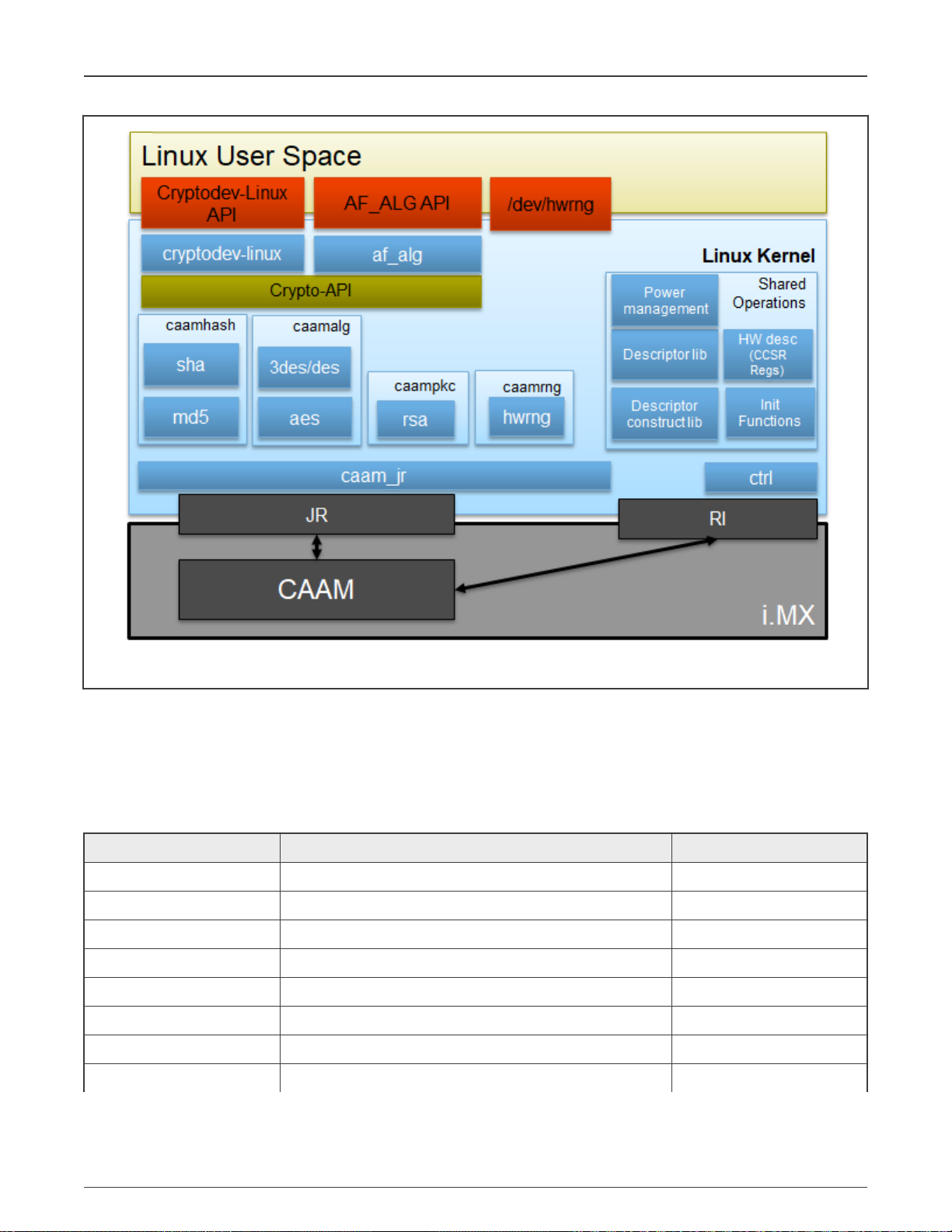
NXP Semiconductors
Security
Figure 3. Kernel CAAM Driver Architecture
10.1.2 Source files
The drivers source code is maintained in the Linux kernel source tree, under drivers/crypto/caam.The following is a
non-exhaustive list of files, mapping to CAAM (some files have been omitted because their existence is justified only by driver logic
or design).
Table 56. Source files
Source File(s) Description Module name
ctrl.[c,h] Init (global settings, RNG, power management, etc.) caam
desc.h HW description (CCSR registers, etc.) N/A
desc_constr.h Inline append - descriptor construction library N/A
caamalg_desc.[c,h] (Shared) Descriptors library (symmetric encryption, AEAD) caamalg_desc
caamhash_desc.[c,h] (Shared) Descriptors library (HASH) caamhash_desc
caamrng.c RNG (runtime) N/A
caamkeyblob_desc.[c,h] Descriptors library (black keys and blobs) caamkeyblob_desc
jr.[c,h] JRI backend caam_jr
Table continues on the next page...
i.MX Linux® User's Guide, Rev. LF5.10.9_1.0.0, 31 March 2021
User's Guide 71 / 103
Page 72
NXP Semiconductors
Security
Table 56. Source files (continued)
Source File(s) Description Module name
caamalg.c JRI frontend (symmetric encryption, AEAD) N/A
caamhash.c JRI frontend (hashing) N/A
caampkc.c, pkc_desc.c JRI frontend (public key cryptography) N/A
caamkeyblob.[c,h] JRI frontend (black keys and blobs) N/A
caamkeygen.c IOCTL calls for key and blob generation/import N/A
10.1.3 Module loading
CAAM backend drivers can be compiled either built-in or as modules. Frontend drivers are linked to the backend driver. See
Section Source files for the list of module names and Section Kernel configuration for how kernel configuration looks like and a
mapping between menu entries and modules and/or functionalities enabled.
10.1.4 Kernel configuration
The designated driver should be configured in the kernel by default for the target platform. If unsure, check
CONFIG_CRYPTO_DEV_FSL_CAAM, which is located in the "Cryptographic API" -> "Hardware crypto devices" sub-menu
in the kernel configuration.
Table 57. Kernel configuration tree view
Kernel configuration tree view option Description
---Cryptographic API --->
[*] Hardware crypto devices --->
<*>CAAM/SNVS Security Violation Handler (EXPERIMENTAL)
<*>Freescale CAAM-Multicore platform driver backend
[ ] Enable debug output in CAAM driver
<*> Freescale CAAM Job Ring driver backend --->
(9) Job Ring size
[ ] Job Ring interrupt coalescing
[*] Register algorithm implementations with the
Crypto API
[*] Register hash algorithm implementations with
Crypto API
[*] Register public key cryptography
implementations with Crypto API
[*] Register caam device for hwrng API
[*] Register tagged key cryptography
implementations with Crypto API
[ ] Test caam rng
[*] CAAM Secure Memory / Keystore API
(EXPERIMENTAL)
(7) Size of each keystore slot in Secure Memory
<M> CAAM Secure Memory - Keystore Test/Example
(EXPERIMENTAL)
<M> Freescale Job Ring UIO support
Enable CAAM device driver:
• Basic platform driver: Freescale CAAMMulticore platform driver backend
• Backends/interfaces: Freescale CAAM Job
Ring driver backend - JRI
• Frontends/crypto algorithms: symmetric
encryption, AEAD, "stitched" AEAD;
Register algorithm implementations with the
Crypto API - via JRI (caamalg driver)
• Register hash algorithm implementations
with Crypto API - hashing (only via JRI caamhash driver)
• Register public key cryptography
implementations with Crypto API asymmetric/public key (only via JRI caampkc driver)
• Register CAAM device for hwrng API - HW
RNG (only via JRI - caamrng driver)
• Register algorithms supporting tagged key
and generate black keys and encapsulate
them into black blobs
i.MX Linux® User's Guide, Rev. LF5.10.9_1.0.0, 31 March 2021
User's Guide 72 / 103
Page 73

NXP Semiconductors
Security
Table 58. Device tree binding
Property Type Status Description
compatible String Required fsl, sec-vX.Y (preferred) OR
fsl,secX.Y
Sample Device Tree crypto node
crypto@30000 {
compatible = "fsl,sec-v4.0";
fsl,sec-era = <2>;
#address-cells = <1>;
#size-cells = <1>;
reg = <0x300000 0x10000>;
ranges = <0 0x300000 0x10000>;
interrupt-parent = <&mpic>;
interrupts = <92 2>;
clocks = <&clks IMX6QDL_CLK_CAAM_MEM>,
<&clks IMX6QDL_CLK_CAAM_ACLK>,
<&clks IMX6QDL_CLK_CAAM_IPG>,
<&clks IMX6QDL_CLK_EIM_SLOW>;
clock-names = "mem", "aclk", "ipg", "emi_slow";
};
10.1.5 How to test the drivers
Crypto drivers could be validated in two modes: at boot time and at request. To enable crypto testing feature, the kernel needs to
be updated as follows.
Table 59. Kernel configuration
Kernel configuration Description
--- Cryptographic API --->
[ ] Disable run-time self tests
[ ] Enable extra run-time crypto self tests
<M> Testing module
Section from boot log that specify where crypto test are made (If a boot test is passing with success, no information will be reported.
For algorithms with no tests available, a line in dmesg will be printed):
[ 4.647985] alg: No test for authenc(hmac(sha224),ecb(cipher_null)) (authenc-hmac-sha224-ecb-
cipher_null-caam)
[ 4.661181] alg: No test for authenc(hmac(sha256),ecb(cipher_null)) (authenc-hmac-sha256-ecb-
cipher_null-caam)
[ 4.671345] alg: No test for authenc(hmac(sha384),ecb(cipher_null)) (authenc-hmac-sha384-ecb-
cipher_null-caam)
[ 4.681486] alg: No test for authenc(hmac(sha512),ecb(cipher_null)) (authenc-hmac-sha512-ecb-
cipher_null-caam)
[ 4.691608] alg: No test for authenc(hmac(md5),cbc(aes)) (authenc-hmac-md5-cbc-aes-caam)
[ 4.699802] alg: No test for echainiv(authenc(hmac(md5),cbc(aes))) (echainiv-authenc-hmac-md5-cbc-
Deselect the feature that bypass crypto driver validation. By
default, Linux kernel is bypassing crypto driver validation.
Disable run-time self tests that normally take place at
algorithm registration.
Enable extra run-time self tests of registered crypto algorithms,
including randomized fuzz tests. This is intended for developer
use only, as these tests take much longer to run than the
normal self tests.
Enable testing module.
i.MX Linux® User's Guide, Rev. LF5.10.9_1.0.0, 31 March 2021
User's Guide 73 / 103
Page 74

NXP Semiconductors
Security
aes-caam)
[ 4.710445] alg: No test for echainiv(authenc(hmac(sha1),cbc(aes))) (echainiv-authenc-hmac-sha1-
cbc-aes-caam)
[ 4.720488] alg: No test for authenc(hmac(sha224),cbc(aes)) (authenc-hmac-sha224-cbc-aes-caam)
[ 4.734647] alg: No test for echainiv(authenc(hmac(sha224),cbc(aes))) (echainiv-authenc-hmac-
sha224-cbc-aes-caam)
[ 4.750504] alg: No test for echainiv(authenc(hmac(sha256),cbc(aes))) (echainiv-authenc-hmac-
sha256-cbc-aes-caam)
[ 4.762468] alg: No test for authenc(hmac(sha384),cbc(aes)) (authenc-hmac-sha384-cbc-aes-caam)
[ 4.771188] alg: No test for echainiv(authenc(hmac(sha384),cbc(aes))) (echainiv-authenc-hmac-
sha384-cbc-aes-caam)
[ 4.782380] alg: No test for echainiv(authenc(hmac(sha512),cbc(aes))) (echainiv-authenc-hmac-
sha512-cbc-aes-caam)
[ 4.792765] alg: No test for authenc(hmac(md5),cbc(des3_ede)) (authenc-hmac-md5-cbc-des3_ede-caam)
[ 4.801832] alg: No test for echainiv(authenc(hmac(md5),cbc(des3_ede))) (echainiv-authenc-hmac-md5-
cbc-des3_ede-caam)
[ 4.812814] alg: No test for echainiv(authenc(hmac(sha1),cbc(des3_ede))) (echainiv-authenc-hmac-
sha1-cbc-des3_ede-caam)
[ 4.823942] alg: No test for echainiv(authenc(hmac(sha224),cbc(des3_ede))) (echainiv-authenc-hmac-
sha224-cbc-des3_ede-caam)
[ 4.835465] alg: No test for echainiv(authenc(hmac(sha256),cbc(des3_ede))) (echainiv-authenc-hmac-
sha256-cbc-des3_ede-caam)
[ 4.846980] alg: No test for echainiv(authenc(hmac(sha384),cbc(des3_ede))) (echainiv-authenc-hmac-
sha384-cbc-des3_ede-caam)
[ 4.858497] alg: No test for echainiv(authenc(hmac(sha512),cbc(des3_ede))) (echainiv-authenc-hmac-
sha512-cbc-des3_ede-caam)
[ 4.869764] alg: No test for authenc(hmac(md5),cbc(des)) (authenc-hmac-md5-cbc-des-caam)
[ 4.877977] alg: No test for echainiv(authenc(hmac(md5),cbc(des))) (echainiv-authenc-hmac-md5-cbc-
des-caam)
[ 4.888078] alg: No test for echainiv(authenc(hmac(sha1),cbc(des))) (echainiv-authenc-hmac-sha1-
cbc-des-caam)
[ 4.898356] alg: No test for echainiv(authenc(hmac(sha224),cbc(des))) (echainiv-authenc-hmac-
sha224-cbc-des-caam)
[ 4.908994] alg: No test for echainiv(authenc(hmac(sha256),cbc(des))) (echainiv-authenc-hmac-
sha256-cbc-des-caam)
[ 4.919653] alg: No test for echainiv(authenc(hmac(sha384),cbc(des))) (echainiv-authenc-hmac-
sha384-cbc-des-caam)
[ 4.930292] alg: No test for echainiv(authenc(hmac(sha512),cbc(des))) (echainiv-authenc-hmac-
sha512-cbc-des-caam)
[ 4.940688] alg: No test for authenc(hmac(md5),rfc3686(ctr(aes))) (authenc-hmac-md5-rfc3686-ctr-
aes-caam)
[ 4.950372] alg: No test for seqiv(authenc(hmac(md5),rfc3686(ctr(aes)))) (seqiv-authenc-hmac-md5-
rfc3686-ctr-aes-caam)
[ 4.961281] alg: No test for seqiv(authenc(hmac(sha1),rfc3686(ctr(aes)))) (seqiv-authenc-hmac-sha1-
rfc3686-ctr-aes-caam)
[ 4.972281] alg: No test for authenc(hmac(sha224),rfc3686(ctr(aes))) (authenc-hmac-sha224-rfc3686-
ctr-aes-caam)
[ 4.982482] alg: No test for seqiv(authenc(hmac(sha224),rfc3686(ctr(aes)))) (seqiv-authenc-hmac-
sha224-rfc3686-ctr-aes-caam)
[ 4.993903] alg: No test for seqiv(authenc(hmac(sha256),rfc3686(ctr(aes)))) (seqiv-authenc-hmac-
sha256-rfc3686-ctr-aes-caam)
[ 5.005331] alg: No test for seqiv(authenc(hmac(sha384),rfc3686(ctr(aes)))) (seqiv-authenc-hmac-
sha384-rfc3686-ctr-aes-caam)
[ 5.016763] alg: No test for seqiv(authenc(hmac(sha512),rfc3686(ctr(aes)))) (seqiv-authenc-hmac-
sha512-rfc3686-ctr-aes-caam)
[ 5.028023] caam algorithms registered in /proc/crypto
[ 5.157622] caam_jr 31430000.jr2: registering rng-caam
[ 5.206167] caam 31400000.caam: caam pkc algorithms registered in /proc/crypto
i.MX Linux® User's Guide, Rev. LF5.10.9_1.0.0, 31 March 2021
User's Guide 74 / 103
Page 75

NXP Semiconductors
10.2 Crypto algorithms support
• Algorithms supported in the Linux kernel scatterlist Crypto API
The Linux kernel contains various users of the Scatterlist Crypto API, including its IPsec implementation, sometimes referred
to as the NETKEY stack. The driver, after registering supported algorithms with the Crypto API, is therefore used to process
per packet symmetric crypto requests and forward them to the CAAM hardware. Since CAAM hardware processes requests
asynchronously, the driver registers asynchronous algorithm implementations with the crypto API: ahash, skcipher, and
aead with CRYPTO_ALG_ASYNC set in .cra_flags. Different combinations of hardware and driver software version support
different sets of algorithms, so searching for the driver name in /proc/crypto on the desired target system will ensure the
correct report of what algorithms are supported.
• Authenticated Encryption with Associated Data (AEAD) algorithms
These algorithms are used in applications where the data to be encrypted overlaps, or partially overlaps, the data to be
authenticated, as is the case with IPsec and TLS protocols. These algorithms are implemented in the driver such that the
hardware makes a single pass over the input data, and both encryption and authentication data are written out simultaneously.
The AEAD algorithms are mainly for use with IPsec ESP (however there is also support for TLS (1.x) record layer encryption
(KTLS Support)).
CAAM drivers currently supports offloading the following AEAD algorithms:
— "stitched" AEAD: all combinations of { NULL, CBC-AES, CBC-DES, CBC-3DES-EDE, RFC3686-CTR-AES } x HMAC-
{MD-5, SHA-1,-224,-256,-384,-512}
Security
— "true" AEAD: generic GCM-AES, GCM-AES used in IPsec: RFC4543-GCM-AES and RFC4106-GCM-AES
• Encryption algorithms
The CAAM driver currently supports offloading the following encryption algorithms.
• Authentication algorithms
The CAAM driver's ahash support includes keyed (hmac) and unkeyed hashing algorithms.
• Asymmetric (public key) algorithms
Currently, CAAM driver supports RSA-Encrypt and RSA-Decrypt togheter with pkcs1pad (rsa-caam,sha256) driver.
• Algorithms supported by CAAM drivers
root@imx8mqevk:~# cat /proc/crypto | grep caam
driver : pkcs1pad(rsa-caam,sha256)
driver : rsa-caam
driver : cmac-aes-caam
driver : xcbc-aes-caam
driver : md5-caam
driver : hmac-md5-caam
driver : sha256-caam
driver : hmac-sha256-caam
driver : sha224-caam
driver : hmac-sha224-caam
driver : sha1-caam
driver : hmac-sha1-caam
driver : seqiv-authenc-hmac-sha256-rfc3686-ctr-aes-caam
driver : authenc-hmac-sha256-rfc3686-ctr-aes-caam
driver : seqiv-authenc-hmac-sha224-rfc3686-ctr-aes-caam
driver : authenc-hmac-sha224-rfc3686-ctr-aes-caam
driver : seqiv-authenc-hmac-sha1-rfc3686-ctr-aes-caam
driver : authenc-hmac-sha1-rfc3686-ctr-aes-caam
driver : seqiv-authenc-hmac-md5-rfc3686-ctr-aes-caam
driver : authenc-hmac-md5-rfc3686-ctr-aes-caam
driver : echainiv-authenc-hmac-sha256-cbc-des-caam
driver : authenc-hmac-sha256-cbc-des-caam
i.MX Linux® User's Guide, Rev. LF5.10.9_1.0.0, 31 March 2021
User's Guide 75 / 103
Page 76

NXP Semiconductors
driver : echainiv-authenc-hmac-sha224-cbc-des-caam
driver : authenc-hmac-sha224-cbc-des-caam
driver : echainiv-authenc-hmac-sha1-cbc-des-caam
driver : authenc-hmac-sha1-cbc-des-caam
driver : echainiv-authenc-hmac-md5-cbc-des-caam
driver : authenc-hmac-md5-cbc-des-caam
driver : echainiv-authenc-hmac-sha256-cbc-des3_ede-caam
driver : authenc-hmac-sha256-cbc-des3_ede-caam
driver : echainiv-authenc-hmac-sha224-cbc-des3_ede-caam
driver : authenc-hmac-sha224-cbc-des3_ede-caam
driver : echainiv-authenc-hmac-sha1-cbc-des3_ede-caam
driver : authenc-hmac-sha1-cbc-des3_ede-caam
driver : echainiv-authenc-hmac-md5-cbc-des3_ede-caam
driver : authenc-hmac-md5-cbc-des3_ede-caam
driver : echainiv-authenc-hmac-sha256-cbc-aes-caam
driver : authenc-hmac-sha256-cbc-aes-caam
driver : echainiv-authenc-hmac-sha224-cbc-aes-caam
driver : authenc-hmac-sha224-cbc-aes-caam
driver : echainiv-authenc-hmac-sha1-cbc-aes-caam
driver : authenc-hmac-sha1-cbc-aes-caam
driver : echainiv-authenc-hmac-md5-cbc-aes-caam
driver : authenc-hmac-md5-cbc-aes-caam
driver : authenc-hmac-sha256-ecb-cipher_null-caam
driver : authenc-hmac-sha224-ecb-cipher_null-caam
driver : authenc-hmac-sha1-ecb-cipher_null-caam
driver : authenc-hmac-md5-ecb-cipher_null-caam
driver : gcm-aes-caam
driver : rfc4543-gcm-aes-caam
driver : rfc4106-gcm-aes-caam
driver : ecb-arc4-caam
driver : ecb-des3-caam
driver : tk-ecb-aes-caam
driver : ecb-aes-caam
driver : ecb-des-caam
driver : rfc3686-ctr-aes-caam
driver : ctr-aes-caam
driver : cbc-des-caam
driver : cbc-3des-caam
driver : tk-cbc-aes-caam
driver : cbc-aes-caam
root@imx8mqevk:~#
Security
10.3 CAAM Job Ring backend driver specifications
CAAM Job Ring backend driver (caam_jr) implements and uses the job ring interface (JRI) for submitting crypto API service
requests from the frontend drivers (caamalg, caamhash, caampkc, caamrng, caamkeyblob) to CAAM engine.
CAAM drivers have a few options, most notably hardware job ring size and interrupt coalescing. They can be used to fine-tune
performance for a particular use case.
The option Freescale CAAM Job Ring driver backend enables the Job Ring backend (caam_jr). The sub-option Job Ring Size
allows the user to select the size of the hardware job rings. If requests arrive at the driver enqueue entry point in a bursty
nature, the bursts' maximum length can be approximated. The user can set the greatest burst length to save performance and
memory consumption.
The sub-option Job Ring interrupt coalescing allows the user to select the use of the hardware's interrupt coalescing feature. Note
that the driver already performs IRQ coalescing in software, and zero-loss benchmarks have in fact produced better results with
this option turned off. If selected, two additional options become effective:
i.MX Linux® User's Guide, Rev. LF5.10.9_1.0.0, 31 March 2021
User's Guide 76 / 103
Page 77

NXP Semiconductors
Security
•
Job Ring interrupt coalescing count threshold
(CRYPTO_DEV_FSL_CAAM_INTC_THLD) Device Drivers. Selects the
value of the descriptor completion threshold, in the range 1-256. A selection of 1 effectively defeats the coalescing feature,
and any selection equal or greater than the selected ring size will force timeouts for each interrupt.
•
Job Ring interrupt coalescing timer threshold
(CRYPTO_DEV_FSL_CAAM_INTC_TIME_THLD) Selects the value of the
completion timeout threshold in multiples of 64 CAAM interface clocks, to which, if no new descriptor completions occur
within this window (and at least one completed job is pending), then an interrupt will occur. This is selectable in the range
1-65535.
The options to register to Crypto API, hwrng API respectively, allow the frontend drivers to register their algorithm capabilities with
the corresponding APIs. They should be deselected only when the purpose is to perform Crypto API requests in software (on the
GPPs) instead of offloading them on CAAM engine.
caamhash
frontend (hash algorithms) may be individually turned off, since the nature of the application may be such that it prefers
software (core) crypto latency due to many small-sized requests.
caampkc
caamrng
frontend (public key / asymmetric algorithms) can be turned off too, if needed.
frontend (Random Number Generation) may be turned off in case there is an alternate source of entropy available to
the kernel.
caamkeyblob
frontend (algorithms supporting tagged key) can be turned off if tagged keys or blobs are not used.
10.3.1 Verifying driver operation and correctness
Other than noting the performance advantages due to the crypto offload, one can also ensure the hardware is doing the crypto
by looking for driver messages in dmesg. The driver emits console messages at initialization time:
[ 1.830397] caam 30900000.crypto: device ID = 0x0a16040100000000 (Era 9)
[ 1.837113] caam 30900000.crypto: job rings = 2, qi = 0
[ 1.849949] caam algorithms registered in /proc/crypto
[ 1.855972] caam 30900000.crypto: caam pkc algorithms registered in /proc/crypto
[ 1.865564] caam_jr 30901000.jr: registering rng-caam
[ 1.870766] Device caam-keygen registered
If the messages are not present in the logs, either the driver is not configured in the kernel, or no CAAM compatible device tree
node is present in the device tree.
10.3.2 Incrementing IRQs in /proc/interrupts
Given a time period when crypto requests are being made, the CAAM hardware will fire completion notification interrupts on the
corresponding Job Ring:
root@imx8qxpmek:~# cat /proc/interrupts | grep jr
418: 1059 0 0 0 GICv3 485 Level 31430000.jr2
419: 21 0 0 0 GICv3 486 Level 31440000.jr3
root@imx8qxpmek:~#
If the number of interrupts fired increment, then the hardware is being used to do the crypto. If the numbers do not increment, then
check the algorithm being exercised is supported by the driver. If the algorithm is supported, there is a possibility that the driver
is in polling mode (NAPI mechanism) and the hardware statistics in debugfs (inbound/outbound bytes encrypted/protected - see
below) should be monitored.
10.3.3 Verifying the 'self test' fields say 'passed' in /proc/crypto
An entry such as the one below means the driver has successfully registered support for the algorithm with the kernel crypto API:
name : cbc(des)
driver : cbc-des-caam
module : kernel
i.MX Linux® User's Guide, Rev. LF5.10.9_1.0.0, 31 March 2021
User's Guide 77 / 103
Page 78

NXP Semiconductors
Security
priority : 3000
refcnt : 1
selftest : passed
internal : no
type : givcipher
async : yes
blocksize : 8
min keysize : 8
max keysize : 8
ivsize : 8
geniv : <built-in>
Note that although a test vector may not exist for a particular algorithm supported by the driver, the kernel will emit messages
saying which algorithms weren't tested, and mark them as 'passed' anyway:
[ 4.647985] alg: No test for authenc(hmac(sha224),ecb(cipher_null)) (authenc-hmac-sha224-ecb-
cipher_null-caam)
[ 4.661181] alg: No test for authenc(hmac(sha256),ecb(cipher_null)) (authenc-hmac-sha256-ecb-
cipher_null-caam)
[ 4.671345] alg: No test for authenc(hmac(sha384),ecb(cipher_null)) (authenc-hmac-sha384-ecb-
cipher_null-caam)
[ 4.681486] alg: No test for authenc(hmac(sha512),ecb(cipher_null)) (authenc-hmac-sha512-ecb-
cipher_null-caam)
10.4 OpenSSL offload
The Secure Socket Layer (SSL) protocol is the most widely deployed application protocol to protect data during transmission by
encrypting the data using ommonly used cipher algorithms such as AES, DES and 3DES. Apart from encryption, it also provides
message authentication services using hash/digest algorithms such as SHA1 and MD5. SSL is widely used in application web
servers (HTTP) and other applications such as SMTP POP3, IMAP, and Proxy servers, where protection of data in transit is
essential for data integrity. There are various versions of SSL protocol such as TLSv1.0, TLSv1.1, TLSv1.2, TLSv1.3, and DTLS
(Datagram TLS). This document describes NXP SSL acceleration solution on i.MX platforms using OpenSSL:
• OpenSSL software architecture
• Building OpenSSL with hardware offload support
• Examples of OpenSSL Offloading
10.4.1 OpenSSL software architecture
The SSL protocol is implemented as a library in OpenSSL - the most popular library distribution in Linux and BSD systems. The
OpenSSL library has several sub-components such as:
• SSL protocol library
• SSL protocol library Crypto library (Symmetric and Asymmetric cipher support, digest support, etc.)
• Certificate Management
The following figure presents the general interconnect architecture for OpenSSL. Each relevant layer is represented with a clear
separation between Linux User Space and Linux Kernel Space.
i.MX Linux® User's Guide, Rev. LF5.10.9_1.0.0, 31 March 2021
User's Guide 78 / 103
Page 79

NXP Semiconductors
Security
Figure 4. OpenSSL Software stack architecture
10.4.2 OpenSSL's ENGINE interface
OpenSSL Crypto library provides Symmetric and Asymmetric (PKI) cipher support that is used in a wide variety of applications
such as OpenSSH, OpenVPN, PGP, IKE, and XML-SEC. The OpenSSL Crypto library provides software support for:
• Cipher algorithms
• Digest algorithms
• Random number generation
• Public Key Infrastructure
Apart from the software support, the OpenSSL can offload these functions to hardware accelerators through the ENGINE
interface. The ENGINE interface provides callback hooks that integrate hardware accelerators with the crypto library. The callback
hooks provide the glue logic to interface with the hardware accelerators. Generic offloading of cipher and digests algorithms
through Linux kernel is possible with cryptodev engine.
i.MX Linux® User's Guide, Rev. LF5.10.9_1.0.0, 31 March 2021
User's Guide 79 / 103
Page 80

NXP Semiconductors
Security
10.4.3 NXP solution for OpenSSL hardware offloading
The following layers can be observed in NXP's solution for OpenSSL hardware offloading:
• OpenSSL (user space) - implements the SSL protocol
• cryptodev-engine (user space) - implements the OpenSSL ENGINE interface; talks to cryptodev-linux (/dev/crypto) via
ioctls, offloading cryptographic operations in kernel
• cryptodev-linux (kernel space) - Linux module that translates ioctl requests from cryptodev-engine into calls to Linux
Crypto API
• Linux Crypto API (kernel space) - Linux kernel crypto abstraction layer
• CAAM driver (kernel space) - Linux device driver for the CAAM crypto engine
The following are offloaded in hardware in current BSP:
• Symmetric Ciphering operations - AES(CBC, ECB), 3DES(CBC, ECB)
• Digest Operations - SHA(1, 256, 384, 512), MD5
• Public Key Operations - RSA Sign(1k, 2k, 4k) / RSA Verify(1k, 2k, 4k);
10.4.4 Deploying OpenSSL into rootfs
Typically, the imx-image-full includes the OpenSSL and cryptodev modules, but for other Yocto targets, users need to update the
conf file from the build directory. Update conf/local.conf by adding the following line:
CORE_IMAGE_EXTRA_INSTALL+="cryptodev-module openssl-bin"
Restart the build procedure:
bitbake imx-image-full
10.4.5 Running OpenSSL benchmarking tests
Probe the cryptodev-module:
root@imx8qxpmek:~# modprobe cryptodev
[17044.896494] cryptodev: driver 1.10 loaded.
root@imx8qxpmek:~# openssl engine
(devcrypto) /dev/crypto engine
(dynamic) Dynamic engine loading support
root@imx8qxpmek:~#
10.4.5.1 Running OpenSSL benchmarking tests for symmetric ciphering and digest
In the speed test file, a series of performance tests are made to check the performance of the symmetric and digest operations.
The following is described in the OpenSSL test execution:
root@imx8qxpmek:~# openssl speed -engine devcrypto -multi 8 -elapsed -evp aes-128-cbc
Forked child 1
engine "devcrypto" set.
Forked child 2
engine "devcrypto" set.
...
Got: +F:22:aes-128-cbc:378616.72:1611328.00:5084501.33:13994666.67:10731793.98:16219060.40 from 6
Got: +H:16:64:256:1024:8192:16384 from 7
Got: +F:22:aes-128-cbc:120773.33:9344.00:3088298.67:13588480.00:31642965.33:16471967.79 from 7
OpenSSL 1.1.1b 26 Feb 2019
built on: Thu Nov 14 13:22:07 2019 UTC
i.MX Linux® User's Guide, Rev. LF5.10.9_1.0.0, 31 March 2021
User's Guide 80 / 103
Page 81

NXP Semiconductors
Security
options:bn(64,64) rc4(char) des(int) aes(partial) idea(int) blowfish(ptr)
compiler: aarch64-poky-linux-gcc --sysroot=recipe-sysroot -O2 -pipe -g -feliminate-unused-debug-
types -fmacro-prefix-map=
-fdebug-prefix-map= -fdebug-prefix-map= -fdebug-prefix-map= -DOPENSSL_USE_NODELETE -DOPENSSL_PIC -
DOPENSSL_CPUID_OBJ -DOPENSSL_BN_ASM_MONT
-DSHA1_ASM -DSHA256_ASM -DSHA512_ASM -DKECCAK1600_ASM -DVPAES_ASM -DECP_NISTZ256_ASM -DPOLY1305_ASM
-DNDEBUG
evp 2242.05k 9681.05k 35017.46k 106866.86k 127787.74k 130077.23k
root@imx8qxpmek:~#
Additional ciphers that could be benchmarked: aes-192-cbc, aes-256-cbc, aes-128-ecb, aes-192-ecb, aes-256-ecb, aes-128-ctr,
aes-192-ctr, aes-256-ctr, des-cbc,des-cbc, des-ede3-cbc.
Additional digests that could be benchmarked: sha1, sha224, sha256, sha384, sha512, md5.
10.4.5.2 Running OpenSSL speed for Asymmetric ciphers
options: rsa1024, rsa2048, and rsa4096.
root@imx8qxpmek:~# openssl speed -engine devcrypto -multi 8 rsa2048
Forked child 0
Forked child 1
engine "devcrypto" set.
Forked child 2
engine "devcrypto" set.
Forked child 3
engine "devcrypto" set.
...
Got: +F2:2:2048:15.133333:703.166667 from 6
+R2:25951:2048:30.00
Got: +F2:2:2048:17.527491:865.033333 from 7
OpenSSL 1.1.1b 26 Feb 2019
built on: Thu Nov 14 13:22:07 2019 UTC
options:bn(64,64) rc4(char) des(int) aes(partial) idea(int) blowfish(ptr)
compiler: aarch64-poky-linux-gcc --sysroot=recipe-sysroot -O2 -pipe -g -feliminate-unused-debug-
types -fmacro-prefix-map=
-fdebug-prefix-map= -fdebug-prefix-map=
-fdebug-prefix-map= -DOPENSSL_USE_NODELETE -DOPENSSL_PIC -DOPENSSL_CPUID_OBJ -DOPENSSL_BN_ASM_MONT -
DSHA1_ASM -DSHA256_ASM -DSHA512_ASM -DKECCAK1600_ASM -DVPAES_ASM -DECP_NISTZ256_ASM -DPOLY1305_ASM -
DNDEBUG
sign verify sign/s verify/s
rsa 2048 bits 0.008727s 0.000188s 114.6 5313.0
10.5 Disk encryption acceleration
Disk encryption is a technology that protects information by converting it into unreadable code that cannot be deciphered easily
by unauthorized people. Disk encryption uses disk encryption software or hardware to encrypt every bit of data that goes on a disk
or disk volume. It is used to prevent unauthorized access to data storage. On i.MX Applications Processors, the disk encryption
scenarios could be implemented in various ways with different methods of key protection.
This section provides steps to run a transparent storage encryption at block level using DM-Crypt. The figure below presents the
software stack that implements disk encryption.
i.MX Linux® User's Guide, Rev. LF5.10.9_1.0.0, 31 March 2021
User's Guide 81 / 103
Page 82

NXP Semiconductors
Security
Figure 5. Disk Encryption use case
10.5.1 Enabling disk encryption support in kernel
By default, the kernel configuration file enables the Device Mapper configuration and Crypt Target support as modules. Therefore,
to enable disk encryption scenario, after the board is booted up, insert the following modules:
root@imx8mqevk:/# modprobe dm-mod
[ 266.982638] device-mapper: ioctl: 4.41.0-ioctl (2019-09-16) initialised: dm-devel@redhat.com
root@imx8mqevk:/# modprobe dm-crypt
root@imx8mqevk:/# dmsetup targets
crypt v1.19.0
striped v1.6.0
linear v1.4.0
error v1.5.0
If the disk encryption scenario is not enabled, some features in the kernel need to be enabled:
Kernel Configure Tree View Options Description
< Device Drivers --->
[*] Multiple devices driver support (RAID and
LVM) --->
Table continues on the next page...
DM Crypt support enablement in Linux kernel
CONFIG_BLK_DEV_DM=y
i.MX Linux® User's Guide, Rev. LF5.10.9_1.0.0, 31 March 2021
User's Guide 82 / 103
Page 83

NXP Semiconductors
Table continued from the previous page...
Kernel Configure Tree View Options Description
<*> Device mapper support
[ ] Device mapper debugging support
< > Unstriped target (NEW)
<*> Crypt target support
<*> Multipath target
[*] DM uevents
Security
< Cryptographic API --->
<*> User-space interface for hash algorithms
<*> User-space interface for symmetric key
cipher algorithms
<*> User-space interface for AEAD cipher
algorithms
Cryptographic API --->
[*] Hardware crypto devices --->
<*> CAAM/SNVS Security Violation Handler
(EXPERIMENTAL)
<*> Freescale CAAM-Multicore platform driver
backend
[ ] Enable debug output in CAAM driver
<*> Freescale CAAM Job Ring driver backend --->
[*] Register tagged key cryptography
implementations with Crypto API
Enable user space crypto API's to allow simple cryptsetup
benchmarks
Selecting this will register algorithms supporting tagged key,
generate black keys and encapsulate them into black blobs.
10.5.2 User space tools for disk encryption
All the required user space tools needed for DM-Crypt are already installed on the board when using Linux i.MX BSP.
If the required user space tools are not installed in the build, add them by editing the conf/local.conf file and appending:
CORE_IMAGE_EXTRA_INSTALL+="coreutils keyutils lvm2 e2fsprogs-mke2fs utillinux"
• keyutils: provides keyctl, which is required to manage Linux Key retention service.
• lvm2: provides dmsetup utility and libraries to manage device-mapper.
• e2fsprogs-mke2fs: contains necessary tools to create filesystems.
• util-linux: provides blockdev utility needed to read number of sectors from a volume.
10.5.3 DM-Crypt using CAAM's tagged key
In Linux Unified Key Setup (LUKS) mode, to generate the disk encryption key (master key), the user supplies a passphrase, which
is combined with a salt, and then a hash function is applied for a supplied number of rounds. When the user wants to mount an
encrypted volume, the passphrase should be supplied. An alternative could be providing a key file stored in an external drive
containing necessary decryption information. Those approaches are not convenient with embedded devices usage.
The aim of using DM-Crypt with CAAM’s tagged key is to suppress the mechanism of encrypting the master volume key with a
key derived from a user-supplied passphrase. DM-Crypt can also take advantages of tagged key to protect storage volumes from
offline decryption. In addition, the volume could only be opened by the devices that have the same OTPMK burned in the fuses.
For more details, see the Security Reference Manual for specific SoC.
i.MX Linux® User's Guide, Rev. LF5.10.9_1.0.0, 31 March 2021
User's Guide 83 / 103
Page 84

NXP Semiconductors
Security
The tagged key feature is based on CAAM’s black key mechanism. Black key protects user keys against bus snooping while
the keys are being written to or read from memory external to the SoC. CAAM supports two different black key encapsulation
schemes, which are AES-ECB and AES-CCM.
Regarding AES-ECB encryption, the data is a multiple of 16 bytes long and is intended for quick decryption.
The AES-CCM mode is not as fast as AES-ECB mode, but includes a “MAC tag” (integrity check value) that ensures the integrity
of the encapsulated key. A CCM-encrypted black key is always at least 12 bytes longer than the encapsulated key (nonce value
+ MAC tag).
Black keys are session keys; therefore, they are not power-cycles safe. CAAM's blob mechanism provides a method for protecting
user-defined data across system power cycles. It provides both confidentiality and integrity protection. The data to be protected
is encrypted so that it can be safely placed into non-volatile storage before the SoC is powered down.
The following diagram illustrates the changes that have been added to support full disk encryption using tagged key. The CAAM
driver registers new Cryptographic transformations in the kernel to use ECB and CBC blacken keys, tk(ecb(aes)) and tk(cbc(aes)).
The tk prefix refers to Tagged Key.
A Tagged Key is a black key that contains metadata indicating what it is and how to handle it.
Linux OS provides an in-kernel key management and retention facility called Keyrings. Keyring also enables interfaces to allow
accessing keys and performing operations such as add, update, and delete from user-space.
The kernel provides several basic types of keys including keyring, user, and logon.
The CAAM driver has associated a user-space application used to generate a tagged key and encapsulated it into a black blob.
This is also used to import a tagged key from a black blob.
$ ./caam-keygen
CAAM keygen usage: caam-keygen [options]
Options:
create <key_name> <key_enc> <key_mode> <key_val>
<key_name> the name of the file that will contain the black key.
A file with the same name, but with .bb extension, will contain the black blob.
<key_enc> can be ecb or ccm
<key_mode> can be -s or -t.
-s generate a black key from random with the size given in the next argument
-t generate a black key from a plaintext given in the next argument
<key_val> the size or the plaintext based on the previous argument (<key_mode>)
import <blob_name> <key_name>
<blob_name> the absolute path of the file that contains the blob
<key_name> the name of the file that will contain the black key.
By default, the keys and blobs are created in KEYBLOB_LOCATION, which is /data/caam/.
Later, CAAM Tagged Key is added into Linux Key Retention service and managed by user-space application such as keyctl. Black
blobs can be stored on any non-volatile storage.
i.MX Linux® User's Guide, Rev. LF5.10.9_1.0.0, 31 March 2021
User's Guide 84 / 103
Page 85
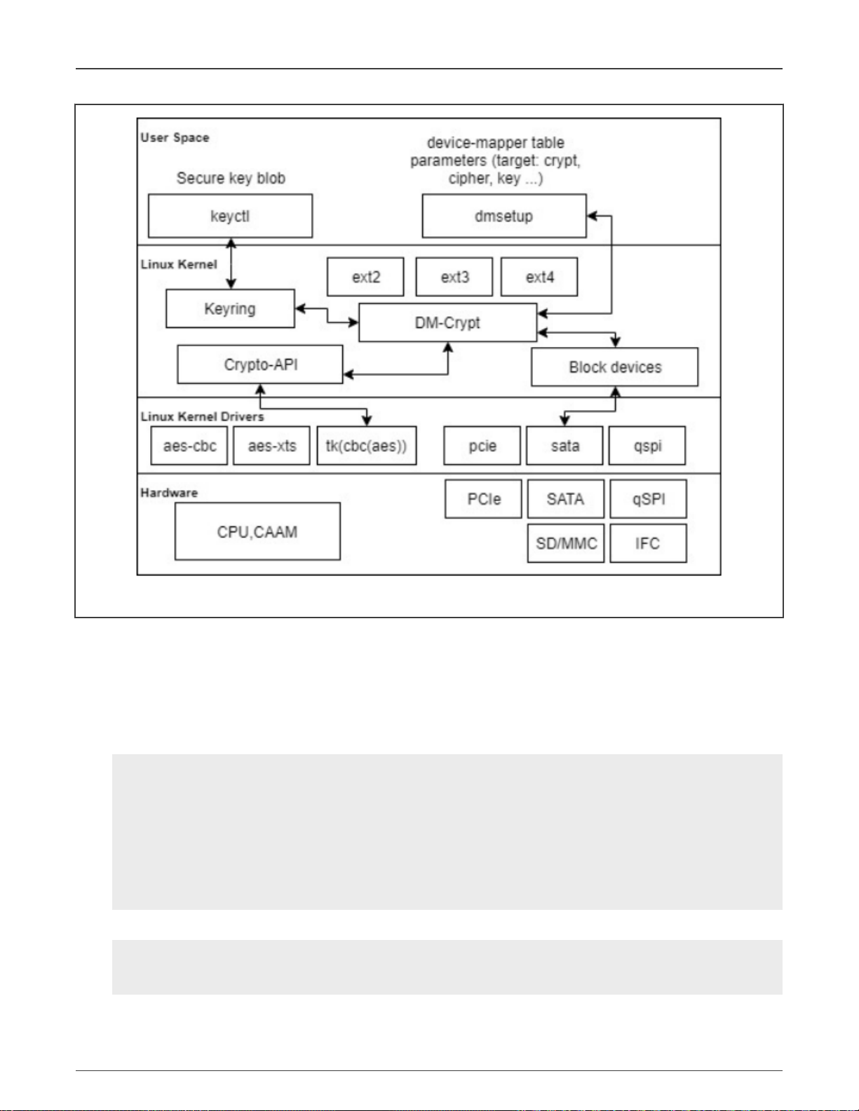
NXP Semiconductors
Security
Figure 6. DM-Crypt using CAAM Tagged key - overall architecture
Dmsetup (part of the libdevmapper package) is a powerful tool for performing very low-level configuration and is used to manage
encrypted volumes.
10.5.4 Usage
The following are the steps to perform a full disk encryption on i.MX devices.
1. After booting the device, make sure that cryptographic transformations using Tagged Key are registered.
root@imx8mqevk:~# grep -B1 -A2 tk- /proc/crypto|grep -v kernel
name : tk(ecb(aes))
driver : tk-ecb-aes-caam
priority : 3000
--
name : tk(cbc(aes))
driver : tk-cbc-aes-caam
priority : 3000
root@imx8mqevk:~#
And caam-keygen application is available:
root@imx8mmevk:~# cd /; find -name "caam-keygen"
./usr/bin/caam-keygen
./dev/caam-keygen
i.MX Linux® User's Guide, Rev. LF5.10.9_1.0.0, 31 March 2021
User's Guide 85 / 103
Page 86

NXP Semiconductors
./sys/class/misc/caam-keygen
./sys/devices/virtual/misc/caam-keygen
For now, we only support AES algorithms. Therefore, the size of the key accepted for encryption/decryption is 16, 24, and
32 bytes.
2. Make sure DM-Crypt is enabled.
root@imx8mqevk:~# dmsetup targets
crypt v1.19.0
striped v1.6.0
linear v1.4.0
error v1.5.0
If any of the above is missing, check Kernel configurations or see section Enable disk encryption support in kernel.
3. Then, provide the device with its key, the black key, which could be created either from a defined plain key or randomly.
Here is an example for black key encrypted with ECB, from a given plaintext of size 16 bytes:
root@imx8mqevk:~# ./caam-keygen create fromTextkey ecb -t 0123456789abcdef
The result is a Tagged Key and a Blob files written to filesystem (the default location is /data/caam). The used key
encryption scheme is ECB.
Security
root@imx8mqevk:~# ls -la /data/caam/
total 16
drwxr-xr-x 2 root root 4096 Aug 25 15:38 .
drwxr-xr-x 3 root root 4096 Aug 25 15:38 ..
-rw-r--r-- 1 root root 36 Aug 25 15:38 fromTextkey
-rw-r--r-- 1 root root 96 Aug 25 15:38 fromTextkey.bb
Next, add the key in key retention service, using keyctl:
root@imx8mqevk:~# cat /data/caam/fromTextkey | keyctl padd logon logkey: @s
876928653
4. Create a secure volume. It could be a physical partition. In this example, make use of an image file and mount it later.
root@imx8mqevk:~# dd if=/dev/zero of=encrypted.img bs=1M count=32
32+0 records in
32+0 records out
33554432 bytes (34 MB, 32 MiB) copied, 3.20227 s, 10.5 MB/s
root@imx8mqevk:~#
root@imx8mqevk:~# losetup /dev/loop0 encrypted.img
root@imx8mqevk:~#
5. Use dmsetup to create a new device-mapper device named encrypted for example, and specify the mapping table. The
table can be provided on stdin or as argument.
root@imx8mqevk:~# dmsetup -v create encrypted --table "0 $(blockdev --getsz /dev/loop0) crypt
capi:tk(cbc(aes))-plain :36:logon:logkey: 0 /dev/loop0 0 1 sector_size:512"
Name: encrypted
State: ACTIVE
Read Ahead: 256
Tables present: LIVE
Open count: 0
Event number: 0
Major, minor: 253, 0
Number of targets: 1
i.MX Linux® User's Guide, Rev. LF5.10.9_1.0.0, 31 March 2021
User's Guide 86 / 103
Page 87

NXP Semiconductors
The following is a breakdown of the mapping table:
• start means encrypting begins with sector 0.
• size is the size of the volume in sectors.
• blockdev gets the number of sectors of the device.
• target is crypt.
• cipher is set in Kernel Crypto API format to use Tagged Key. cipher set to capi:tk(cbc(aes))-plain and key set
to :36:logon:logkey: leads to use of the logon key with CAAM Tagged Key transformation.
• IV is the Initialization Vector defined to plain, initial vector, which is the 32-bit little-endian version of the sector number,
padded with zeros if necessary.
• key type is the Keyring key service type, set to Logon Key. 36 is the key size in bytes.
• key name is the key description to identify the key to load.
• IV offset is the value to add to sector number to compute the IV value.
• device is the path to device to be used as backend; it contains the encrypted data.
• offset represents encrypted data begins at sector 0 of the device.
• optional parameters represent the number of optional parameters.
• sector_size specifies the encryption sector size.
Security
For more detailed options and descriptions, refer to https://gitlab.com/cryptsetup/cryptsetup/-/wikis/DMCrypt.
The created device appears in /dev/mapper:
root@imx8mqevk:~# dmsetup table --showkey encrypted
0 65536 crypt capi:tk(cbc(aes))-plain :36:logon:logkey: 0 7:0 0
6. Create a file system on the device.
root@imx8mqevk:~# mkfs.ext4 /dev/mapper/encrypted
mke2fs 1.45.3 (14-Jul-2019)
Creating filesystem with 32768 1k blocks and 8192 inodes
Filesystem UUID: 3ba01ad8-ba03-4389-a955-5136b3173c35
Superblock backups stored on blocks:
8193, 24577
Allocating group tables: done
Writing inode tables: done
Creating journal (4096 blocks): done
Writing superblocks and filesystem accounting information:l done
7. Set up a mount point.
root@imx8mqevk:~# mkdir /mnt/encrypted
8. Mount the mapped device.
root@imx8mqevk:~# mount -t ext4 /dev/mapper/encrypted /mnt/encrypted/
[ 9409.936183] EXT4-fs (dm-0): mounted filesystem with ordered data mode. Opts: (null)
[ 9409.943892] ext4 filesystem being mounted at /mnt/encrypted supports timestamps until
2038 (0x7fffffff)
9. Write to device.
root@imx8mqevk:~# echo "This is an encrypt with black key (ECB from text 16 bytes key size) test
of full disk encryption on i.MX" > /mnt/encrypted/readme.txt
i.MX Linux® User's Guide, Rev. LF5.10.9_1.0.0, 31 March 2021
User's Guide 87 / 103
Page 88

NXP Semiconductors
10. Unmount the device.
root@imx8mqevk:~# umount /mnt/encrypted/
11. Deactivate the device mapper device.
root@imx8mqevk:~# dmsetup remove encrypted
12. Restart the board.
root@imx8mqevk:~# reboot
...
root@imx8mqevk:~#
13. Import the key from blob and add it to key retention service.
root@imx8mqevk:~# ./caam-keygen import /data/caam/fromTextkey.bb importKey
root@imx8mqevk:~# cat /data/caam/importKey | keyctl padd logon logkey2: @s
605536287
root@imx8mqevk:~# ls -la /data/caam/
total 20
drwxr-xr-x 2 root root 4096 Aug 25 15:47 .
drwxr-xr-x 3 root root 4096 Aug 25 15:38 ..
-rw-r--r-- 1 root root 36 Aug 25 15:38 fromTextkey
-rw-r--r-- 1 root root 96 Aug 25 15:38 fromTextkey.bb
-rw-r--r-- 1 root root 36 Aug 25 15:47 importKey
root@imx8mqevk:~#
Security
14. Mount the encrypted device.
root@imx8mqevk:~# losetup /dev/loop0 encrypted.img
root@imx8mqevk:~#
15. Specify the mapping table to encrypt the volume using dmsetup.
root@imx8mqevk:~# dmsetup -v create encrypted --table "0 $(blockdev --getsz /dev/loop0) crypt
capi:tk(cbc(aes))-plain :36:logon:logkey2: 0 /dev/loop0 0 1 sector_size:512"
Name: encrypted
State: ACTIVE
Read Ahead: 256
Tables present: LIVE
Open count: 0
Event number: 0
Major, minor: 253, 0
Number of targets: 1
16. Mount.
root@imx8mqevk:~# mount /dev/mapper/encrypted /mnt/encrypted/
[ 191.961828] EXT4-fs (dm-0): mounted filesystem with ordered data mode. Opts: (null)
[ 191.969533] ext4 filesystem being mounted at /mnt/encrypted supports timestamps until
2038 (0x7fffffff)
root@imx8mqevk:~
17. Read from the device.
root@imx8mqevk:~# cat /mnt/encrypted/readme.txt
This is an encrypt with black key (ECB from text 16 bytes key size) test of full disk
i.MX Linux® User's Guide, Rev. LF5.10.9_1.0.0, 31 March 2021
User's Guide 88 / 103
Page 89

NXP Semiconductors
encryption on i.MX.
root@imx8mqevk:~#
18. Unmount the device and deactivate the device mapper device.
root@imx8mqevk:~# umount /mnt/encrypted/; dmsetup remove encrypted
Security
i.MX Linux® User's Guide, Rev. LF5.10.9_1.0.0, 31 March 2021
User's Guide 89 / 103
Page 90

NXP Semiconductors
Chapter 11
Connectivity
This section describes the connectivity for Bluetooth wireless technology and Wi-Fi, as well as for USB type-C.
11.1 Connectivity for Bluetooth wireless technology and Wi-Fi
Bluetooth and Wi-Fi are supported on i.MX through on-board chip solutions and external hardware. The following table lists
the various on-board chips and external solutions. When i.MX uses the Azurewave CM358 uSD card, it requires a hardware
modification on boards.
Table 60. On-board chips and external solutions for Bluetooth and Wi-Fi support
SoC On-board chip PCIe uSD card or uSD-to-M.2
baseboard
8QuadXPlus/8DXL - NXP 88W8997 (tested with
AW-CM276MA)
8QuadMax - NXP 88W8997 (tested with
AW-CM276MA)
8MQuad - NXP 88W8997 (tested with
AW-CM276MA)
8M Nano
8M Mini
7ULP - - NXP 88W8987 (tested with
7Dual - - NXP 88W8987 (tested with
6QuadPlus/Quad/Dual/Solo - - NXP 88W8987 (tested with
6SLL/6UltraLite/6ULL/6ULZ - - NXP 88W8987 (tested with
NXP 88W8987 (tested with
AzureWave AW-CM358SM)
NXP 88W8987 (tested with
AzureWave AW-CM358SM)
- -
- -
-
-
-
AW-CM358-uSD)
AW-CM358-uSD)
AW-CM358-uSD)
AW-CM358-uSD)
8M Plus - NXP 88W8997 (tested with
AW-CM276MA)
The wireless driver supports wpa_supplicant, which is a WEP/WPA/WPA2/WPA3 encryption authenticated tool.
• Wi-Fi driver: supports NXP 88W8987-based modules with SDIO interface, NXP 88W8997-based modules with
PCIe interface.
• Firmware
The NXP release package already includes all NXP, Wi-Fi/Bluetooth firmware. It requires to accept NXP license.
To run Wi-Fi, execute the following commands first and follow common commands below:
i.MX Linux® User's Guide, Rev. LF5.10.9_1.0.0, 31 March 2021
User's Guide 90 / 103
-
Page 91

NXP Semiconductors
• For NXP 88w8997:
modprobe moal mod_para=nxp/wifi_mod_para.conf
• For NXP 88w8987:
modprobe moal mod_para=nxp/wifi_mod_para.conf
(Follow common step below)
• For Common Step, execute these commands using connman
wpa_passphrase SSID SSID_PASSWD >> /etc/wpa_supplicant.conf
wpa_supplicant -d -B -i mlan0 -c /etc/wpa_supplicant.conf -Dnl80211
Run below command first time.
$connmanctl
connmanctl> scan wifi
connmanctl> services /* This should list of the network. For
example wifi_c0e4347f5053_4a62726f_managed_psk*/
connmanctl> agent on
connmanctl> connect wifi_c0e4347f5053_4a62726f_managed_psk /* Enter Passphrase */
Agent RequestInput wifi_c0e4347f5053_4a62726f_managed_psk
Passphrase = [ Type=psk, Requirement=mandatory ]
Passphrase?
connmanctl> quit
Connectivity
To run NXP Bluetooth with BlueZ stack, execute the following commands (it requires load Wi-Fi first to load Bluetooth firmware):
hciattach <device> any 115200 flow
hciconfig hci0 up
hcitool -i hci0 cmd 0x3f 0x0009 0xc0 0xc6 0x2d 0x00
killall hciattach
hciattach <device> any -s 3000000 3000000 flow
hciconfig hci0 up
NOTE
• Device: /dev/ttymxcN or /dev/ttyLPN.
• Different boards have different devices.
The i.MX 6 boards require board rework to support the bluetooth WiFI enablement as well as running with the btwifi device tress.
The following is a list of the hardware modifications required and possibly conflicts caused by these modifications.
• i.MX 6QuadPlus/Quad/Dual/DualLite/Solo: See https://community.nxp.com/docs/DOC-94235. This change HAS a pin
conflict with: EPDC/SPI-NOR/GPIO-LED.
• i.MX 6SoloX: Install R328, and disconnect R327. Connect with SD2 slot and BLUETOOTH CABLE CONNECTOR J19. It
has no Pin conflict with other modules.
• i.MX 6SLL: Install R127, and double check to ensure R126 and R128 are installed. Connect with SD3 slot and
BLUETOOTH CABLE CONNECTOR J4. It has no Pin conflict with other modules.
• i.MX 6UL/ULL/ULZ: Install R1701. It has no Pin conflict with other modules.
11.2 Connectivity for USB type-C
The following describes the connectivity for USB type-C and power delivery connection on the i.MX 8QuadXPlus MEK board.
i.MX Linux® User's Guide, Rev. LF5.10.9_1.0.0, 31 March 2021
User's Guide 91 / 103
Page 92

NXP Semiconductors
Connectivity
• The Linux release includes USB type-C and PD stack, which is enabled by default. The specific power parameters are passed
in by DTS. The following fsl-imx8qxp-mek is an example:
typec_ptn5110: typec@50 {
compatible = "usb,tcpci";
pinctrl-names = "default";
pinctrl-0 = <&pinctrl_typec>;
reg = <0x50>;
interrupt-parent = <&gpio1>;
interrupts = <3 IRQ_TYPE_LEVEL_LOW>;
ss-sel-gpios = <&gpio5 9 GPIO_ACTIVE_LOW>;
reset-gpios = <&pca9557_a 7 GPIO_ACTIVE_HIGH>;
src-pdos = <0x380190c8>;
snk-pdos = <0x380190c8 0x3802d0c8>;
max-snk-mv = <9000>;
max-snk-ma = <1000>;
op-snk-mw = <9000>;
port-type = "drp";
sink-disable;
default-role = "source";
status = "okay";
};
For power capability related configuration, users need to check the PD specification to see how to composite the PDO value.
To make it support power source role for more voltages, specify the source PDO. The i.MX 8QuadXPlus board can support
5 V and 12 V power supply.
• The Linux BSP of the Alpha and Beta releases on the i.MX 8QuadXPlus MEK platform only supports power source role for 5 V.
• Users can use /sys/kernel/debug/tcpm/2-0050 to check the power delivery state, which is for debugging purpose information.
• Booting only by type-C port power supply is not supported on the Alpha release.
11.3 NXP Bluetooth/Wi-Fi information
The NXP Bluetooth/Wi-Fi information is as follows:
• SoC version: 88W8987
• Wi-Fi firmware version: 16.92.10.p208
— 16: Major revision
— 92: Feature pack
— 10: Re ease version
— p207: Patch number
• Bluetooth-Bluetooth LE firmware version: 16.92.10.p208
— 16: Major revision
— 92: Feature pack
— 10: Release version
— p207: Patch number
• Driver version: MXM5X16210-MGPL
— 5X: Linux 5.x
— 16186: Release version
— p7: Patch number
i.MX Linux® User's Guide, Rev. LF5.10.9_1.0.0, 31 March 2021
User's Guide 92 / 103
Page 93

NXP Semiconductors
— MGPL: General
Tested using perf version 2.0.5.
11.4 Certification
11.4.1 WFA certification
The following table lists the WFA certification.
Table 61. WFA certification
STA Certification
STA 802.11n
STA 802.11ac
STA WPS2.0
STA PMF
STA WMM-PS
STA WPA3
Connectivity
For details, see Wi-Fi Alliance Derivative Certification (AN12976).
11.4.2 Bluetooth controller certification
Listing details: https://launchstudio.bluetooth.com/ListingDetails/115533
11.5 Wi-Fi throughput
11.5.1 Throughput test setup
The throughput test setup is as follows:
• Environment: Shield Room - Over the Air
• Access Point: Linksys WRT1900AC
• DUT: 88W8987-Azurewave (Model: AW-CM358MA) with i.MX 8M Quad platform
• Client: Apple Macbook Air
• Channel: 6 | 36
i.MX Linux® User's Guide, Rev. LF5.10.9_1.0.0, 31 March 2021
User's Guide 93 / 103
Page 94

NXP Semiconductors
Chapter 12
Virtualization
12.1 Xen overview
Xen project is a hypevisor using a microkernel design, providing services that allow multiple operating systems to run on the same
hardware with hardware capability. It is widely used on Cloud and is also used in embedded systems.
12.2 Basic architecture
The following figure shows the basic architecture of Xen.
Figure 7. Basic architecture of Xen
12.3 Xen xl
For detailed Xen xl usage, see https://xenbits.xen.org/docs/unstable/man/xl.cfg.5.html.
12.4 How to boot multiple operating systems on i.MX 8QuadMax EVK
To boot two Yocto operating systems, partition the SD card (no less than 16 GB) with three partitions. The first partition is FAT,
used to hold Xen, image, and imx8qm-mek-dom0.dtb. The second and third partitions are used to hold Yocto rootfs.
In the U-Boot stage:
• To boot from the SD card, run xenmmcboot.
• To boot from the network, run xennetboot.
After the first Linux OS is boot up, perform the following steps:
1. Umount /dev/mmcblk1p3; insmod /lib/modules/`uname -r`/kernel/driver/block/xen-blkback/xen-
blkback.ko; xl create /etc/xen/domu-imx8qm-mek.cfg.
2. Use xl list to view the running domains.
3. Use xl console DomU to attach to the console of DomU.
4. Press ctrl + ] to exit the console of DomU.
i.MX Linux® User's Guide, Rev. LF5.10.9_1.0.0, 31 March 2021
User's Guide 94 / 103
Page 95

NXP Semiconductors
An example of the DomU configuration file is as follows:
kernel = "/home/root/xen/Image"
device_tree = "/home/root/xen/imx8qm-mek-domu.dtb"
disk = [ 'format=raw,access=rw,vdev=xvda,target=/dev/mmcblk1p3' ]
cmdline = "no_console_suspend console=hvc0 root=/dev/xvda rw"
name = "DomU"
on_reboot="soft-reset"
memory = "3584"
vcpus = 1
cpus = ['3']
dtdev = [
#usbotg3:
'/usb3@5b110000',
#camera:
'/camera/isi@58100000',
#cryto:
'/caam@0x31400000',
#vpu:
'/vpu_decoder@2c000000',
#usdhc1:
'/usdhc@5b010000',
#dpu2:
'/dpu@57180000',
#gpu_3d1:
'/gpu@54100000',
#usb_otg1:
'/usb@5b0d0000',
#usbphy1:
#'/usbphy@0x5b100000',
#edma01:
'/dma-controller1@5a1f0000',
#cm41:
'/cm41@1',
#pciea:
'/pcie@0x5f000000',
]
iomem = [
#usbotg3:
"0x5b110,0x10@0x5b110",
"0x5b130,0x10@0x5b130",
"0x5b140,0x10@0x5b140",
"0x5b160,0x40@0x5b160",
"0x5b120,0x10@0x5b120",
#usbotg3_lpcg:
"0x5b280,0x1@0x5b280",
#camera
#isi_lpcg:
"0x58500,0x1@0x58500",
"0x58510,0x1@0x58510",
"0x58520,0x1@0x58520",
"0x58530,0x1@0x58530",
#isi_0:
"0x58100,0x10@0x58100",
#isi_1:
"0x58110,0x10@0x58110",
#isi_2:
"0x58120,0x10@0x58120",
#isi_3:
"0x58130,0x10@0x58130",
Virtualization
i.MX Linux® User's Guide, Rev. LF5.10.9_1.0.0, 31 March 2021
User's Guide 95 / 103
Page 96

NXP Semiconductors
#mipi_csi_0:
"0x58227,0x1@0x58227",
"0x58221,0x1@0x58221",
#i2c0_mipi_csi0:
"0x58226,0x1@0x58226",
#irqsteer_csi0:
"0x58220,0x1@0x58220",
#gpio0_mipi_csi0:
"0x58222,0x1@0x58222",
#lpcg:
"0x58223,0x1@0x58223",
"0x58580,0x1@0x58580",
#end camera
#cryto:
"0x31400,0x400@0x31400",
#caam_sm:
"0x31800,0x10@0x31800",
#vpu mu_m0:
"0x2d000,0x10@0x2d000",
#vpu mu1_m0:
"0x2d020,0x10@0x2d020",
#vpu mu2_m0:
"0x2d040,0x10@0x2d040",
#vpu_decoder:
"0x2c000,0x1000@0x2c000",
#vpu_decoder_csr:
"0x2d080,0x1@0x2d080",
#vpu_decoder:
"0x2d000,0x1000@0x2d000",
#vpu_reserved:
"0x84000,0x2000@0x84000",
"0x86000,0x2000@0x86000",
"0x90400,0x1000@0x90400",
"0x91400,0x1000@0x91400",
"0x94400,0x1800@0x94400",
#hsio_pcie_x2_lpcg:
"0x5f050,0x10@0x5f050",
#hsio_pcie_x1_lpcg:
"0x5f060,0x10@0x5f060",
#hsio_phy_x2_lpcg:
"0x5f080,0x10@0x5f080",
#hsio_pcie_x2_crr2:
"0x5f0c0,0x10@0x5f0c0",
#hsio:
"0x5f080,0xf0@0x5f080",
#pciea:
"0x5f000,0x10@0x5f000",
"0x6ff00,0x80@0x6ff00",
#mu2:
"0x5d1d0,0x10@0x5d1d0",
#usb_otg1:usbmisc1:
"0x5b0d0,0x1@0x5b0d0",
#usbphy1:
"0x5b100,0x1@0x5b100",
#usblpcg:
"0x5b270,0x1@0x5b270",
#usdhc1:
"0x5b010,0x10@5b010",
#usdhc1_lpcg:
"0x5b200,0x1@5b200",
Virtualization
i.MX Linux® User's Guide, Rev. LF5.10.9_1.0.0, 31 March 2021
User's Guide 96 / 103
Page 97

NXP Semiconductors
#lvds_region2 irqsteer_lvds2:
"0x57240,0x10@0x57240",
#dpu2_irqsteer:
"0x57000,0x10@0x57000",
#dpu2:
"0x57180,0x40@0x57180",
#pixel_combiner2:
"0x57020,0x10@0x57020",
#dc_1_lpcg:
"0x57010,0x10@0x57010",
#gpu_3d1:
"0x54100,0x40@0x54100",
#prg, dpr:
"0x57040,0xf0@0x57040",
#edma01:
"0x5a2e0,0x20@0x5a2e0",
#lpuart1_lpcg:
"0x5a470,0x10@0x5a470",
#lpuart1:
"0x5a070,0x1@0x5a070",
#mu6_lpcg1:
"0x5d610, 0x10@0x5d610",
#rpmsg1:
"0x90000, 0x400@0x90000",
#mu_rpmsg1_A:
"0x5d210, 0x10@0x5d210",
#The following iomem is to let CM41 with SMMU enabled work correctly
#mu_rpmsg1_B:
"0x5d2a0, 0x10@0x5d2a0",
#mu6_lpcg1_b:
"0x5d6a0, 0x10@0x5d6a0",
#mu7_lpcg1_b:
"0x5d6b0, 0x10@0x5d6b0",
#irqsteer_cm41:
"0x51080, 0x10@0x51080",
#lpuart2_lpcg:
"0x5a480,0x10@0x5a480",
#lpuart2:
"0x5a080,0x1@0x5a080",
]
irqs = [
#usbotg3,
303,
#gpio4:
172,
#irqsteer_csi0
352,
#isi
329,
330,
331,
332,
#crypto
180,
485,
486,
#vpu
504,
505,
506,
Virtualization
i.MX Linux® User's Guide, Rev. LF5.10.9_1.0.0, 31 March 2021
User's Guide 97 / 103
Page 98
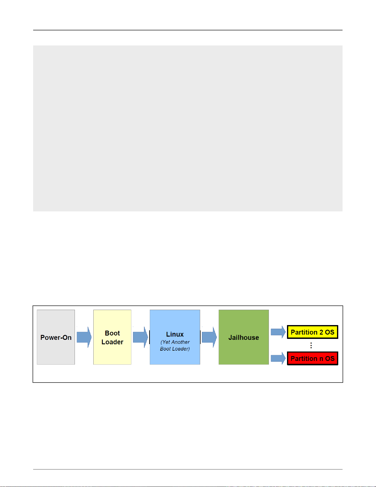
NXP Semiconductors
#pciea
102,
104,
#usdhc1
264,
210,
#usbotg1
299,
#irqsteer_lvds1
90,
#dpu2
184, 185, 186, 187, 188, 189, 190, 191, 194, 195,
#gpu_3d1
97,
#lpuart1,
378,
#edma01,
468, 469,
#mu_rpmsg1,
217,
]
serial="pty"
#vif = [ 'bridge=br0' ]
vi2c = ["backend=0,be-adapter=5a800000.i2c,slaves=0x51;0x44;0x1e;0x20;0x60"]
Virtualization
12.5 Jailhouse hypervisor
Jailhouse is a static partitioning hypervisor based on Linux OS. It can run bare-metal applications or other operating systems
besides Linux. It does not support virtual CPU schedule and only virtualizes those resources in software. This is essential for a
platform and cannot be partitioned in hardware. It configures CPUs and devices into different domains, called "cells".
When Jailhouse is activated, it runs bare-metal, which means, it takes full control over the hardware and needs no external
support. However, in contrast to other bare-metal hypervisors, it is loaded and configured by a normal Linux system. Its
management interface is based on the Linux infrastructure. Therefore, users need to boot Linux OS first, then enable Jailhouse,
and finally split off parts of the system's resources and assign them to additional cells. The following figure shows the workflow
from board power-on to multi-OS bootup. Jailhouse relies on the Linux OS (another boot loader) to do Jailhouse kernel loading
and initialization.
Figure 8. Workflow from board power-on to multi-OS bootup
To use the Jailhouse, perform the following steps:
1. Execute run jh_mmcboot or run jh_netboot in U-Boot stage.
2. Wait for Linux OS to boot up and login in it.
3. Insmod /lib/modules/`uname -r`/extra/driver/jailhouse.ko.
4. Jailhouse enables /usr/share/jailhouse/cells/[soc].cell.
• Replace [soc] with imx8mm/imx8mq/imx8mn/imx8mp for the boards that you are using.
i.MX Linux® User's Guide, Rev. LF5.10.9_1.0.0, 31 March 2021
User's Guide 98 / 103
Page 99

NXP Semiconductors
• Only the default release boards are supported.
5. Demo:
Note: To test a new demo, destroy the previous running demo with jailhouse cell destroy 1 if you have one running.
• Dual Linux OSs
— The second Linux OS only has minimal features, including eMMC storage and one UART for console and
virtual ivshmem-net.
— Export PATH=$PATH:/usr/share/jailhouse/tools/.
— i.MX 8M Mini LPDDR4
jailhouse cell linux /usr/share/jailhouse/cells/imx8mm-linux-demo.cell /run/media/
mmcblk1p1/Image -d /run/media/mmcblk1p1/imx8mm-evk-inmate.dtb -c "clk_ignore_unused
console=ttymxc3,115200 earlycon=ec_imx6q,0x30890000,115200 root=/dev/mmcblk2p2
rootwait rw"
— i.MX 8M Nano LPDDR4
jailhouse cell linux /usr/share/jailhouse/cells/imx8mn-linux-demo.cell /run/media/
mmcblk1p1/Image -d /run/media/mmcblk1p1/imx8mn-evk-inmate.dtb -c "clk_ignore_unused
console=ttymxc3,115200 earlycon=ec_imx6q,0x30890000,115200 root=/dev/mmcblk2p2
rootwait rw"
Virtualization
— i.MX 8M Quad
jailhouse cell linux /usr/share/jailhouse/cells/imx8mq-linux-demo.cell /run/media/
mmcblk1p1/Image -d /run/media/mmcblk1p1/imx8mq-evk-inmate.dtb -c "clk_ignore_unused
console=ttymxc1,115200 earlycon=ec_imx6q,0x30860000,1115200 root=/dev/mmcblk2p2
rootwait rw"
— i.MX 8M Plus
jailhouse cell linux /usr/share/jailhouse/cells/imx8mp-linux-demo.cell /run/media/
mmcblk1p1/Image -d /run/media/mmcblk1p1/imx8mp-evk-inmate.dtb -c "clk_ignore_unused
console=ttymxc3,115200 earlycon=ec_imx6q,0x30890000,115200 root=/dev/mmcblk2p2
rootwait rw"
— The second inmate Linux OS uses the first Linux UART as early console output. Its normal console uses its own
UART as console output.
— When the second inmate Linux boots up, execute ifconfig eth0 192.168.1.3 in the second inmate Linux OS.
And execute ifconfig eth[x] 192.168.1.4. For i.MX 8M Plus, [x] is 2. For the other platforms, [x] is 1. Then
you could use the network ping command to ping each other.
• IVSHMEM
a. Jailhouse cell creates /usr/share/jailhouse/cells/[soc]-ivshmem-demo.cell.
Replace [soc] with imx8mm/imx8mq/imx8mn/imx8mp/imx8qxp/imx8qm for the boards that you are using.
b. Jailhouse cell loads 1 /usr/share/jailhouse/inmates/ivshmem-demo.bin.
c. Jailhouse cell starts 1.
d. ivshmem-demo /dev/uio[x].
[x] normally the last one under your /dev/ directory.
• GIC
a. Jailhouse cell creates /usr/share/jailhouse/cells/[soc]-gic-demo.cell.
i.MX Linux® User's Guide, Rev. LF5.10.9_1.0.0, 31 March 2021
User's Guide 99 / 103
Page 100

NXP Semiconductors
Replace [soc] with imx8mm/imx8mq/imx8mn/imx8mp/imx8 for the boards that you are using.
b. Jailhouse cell loads 1 /usr/share/jailhouse/inmates/gic-demo.bin.
c. Jailhouse cell starts 1.
6. How to set up network for the second Linux OS using network.
a. After the first Linux OS boots up:
• sysctl -w net.ipv4.ip_forward=1
• sysctl -p /etc/sysctl.conf
b. After the root cell is enabled:
• iptables -A FORWARD -i eth1 -j ACCEPT
• iptables -A FORWARD -o eth1 -j ACCEPT
• iptables -t nat -A POSTROUTING -o eth0 -j MASQUERADE
c. After the second Linux OS boots up:
• ifconfig eth1 or 2 192.168.1.4 for the first Linux OS
• ifconfig eth0 192.168.1.5 for the second Linux OS
• ip route add default via 192.168.1.4 dev eth0 for the second Linux OS
Virtualization
ip route add 10.193.108.0/24 via 192.168.1.4 dev eth0 for the second Linux OS
• Now you could mount -t nfs 10.193.108.xx:/home/xxx/nfs /mnt.
i.MX Linux® User's Guide, Rev. LF5.10.9_1.0.0, 31 March 2021
User's Guide 100 / 103
 Loading...