

Page 1
Quick Start Guide
i.MX Audio Board
Page 2

Quick Start Guide
2
ABOUT THE i.MX AUDIO BOARD
i.MX Audio Board (or
MCIMX8M-AUD
) is an excellent, configurable and functional
audio processing platform. It supports multiple i.MX 8M series processors and HDMI
card. A variety of audio input and output interfaces are integrated into the system, it
supports HDMI input, HDMI eARC, S/PDIF I/O, 2-ch ADC line-in, 24-ch DAC line-out
and so on. Based on these features, rich audio application cases can be realized.
Features
•
24-ch line out
•
2-ch line in
•
S/PDIF I/O
- TOSLINK up to 192kHz for optical
fiber cable
- RCA for coaxial cable
•
Audio in/out on HDMI card
•
eARC on HDMI card
•
eARC on i.MX 8M Plus processor
•
Micro-SD card connector
•
USB with Type-C connector
•
Ethernet
•
M.2 connector
- PCIE for i.MX 8M Plus and i.MX 8M
Mini
- SDIO for i.MX 8M Plus
•
DSI mini-SAS connector
•
USB to serial converter for debug
Page 3
3
www.nxp.com
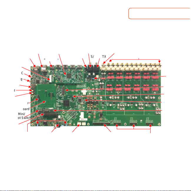
GET TO KNOW THE i.MX AUDIO BOARD
Figure 1: i.MX Audio Board Top View
mini-SAS
Ethernet
HDMI
Only i.MX 8M Plus
HDMI Card
12V Trigger
S/PDIF TX
S/PDIF RX
ADC 2-CH
DAC 24-CH
USB Type-C
USB Debug
Micro-SD
On/Off
Reset
Interposer Board
i.MX 8M Mini/
Nano Boot Switch
8-DMIC
Connector
DC 12V Jack
CPLD Mode Switch
ADC Parallel Jumper
DAC Parallel Jumper
Button Board
Connector
M.2 Connector
SOM Connector
Power Mode Jumper
I2C Connector
CPLD Download
S/PDIF Route
Jumper
Board ID Switch
Page 4
Quick Start Guide
4
GETTING STARTED
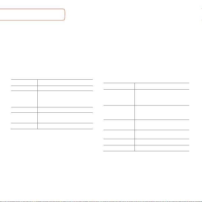
Unpack the Kit
The i.MX Audio Board
is shipped with the
items listed in Table 1. E
nsure the items
are included in the box.
Prepare Accessories
The following items in Table 2 are
recommended to run the i.MX 8M Audio
Board.
Table 2 Customer
Supplied Accessories
ITEM
DESCRIPTION
SOM Boards*
- i.MX 8M Nano SOM Board
- i.MX 8M Mini SOM Board
- i.MX 8M Plus SOM Board
HDMI Display
HDMI display that supports a
minimum resolution of
1080P60
HDMI Cable
HDMI 2.0 cable to connect the
HDMI card to HDMI display
USB Micro-B
Cable
USB Type-A Male to Micro-B Male
Coaxial Cable
RCA cable for line-in and line-out
Fiber Cable
Optical fiber cable for TOSLINK
*Note: SOM Boards from their EVK Boards. For example,
i.MX 8M Nano SOM Board from i.MX 8M Nano DDR4 EVK.
Table 1 Kit Contents
ITEM
DESCRIPTION
EVB Board
i.MX Audio board
Additional
Daughter Cards
- Interposer board
- EP HDMI card
- Button board
Power Supply
12V 5A with DC jack
Accessories
- SCREW-TY PE3 M3X5-5-S x1
- Antenna x3
Documentation
Quick Start Guide
Page 5

www.nxp.com
5
GETTING STARTED
CONTINUED
Download Software and Tools
Installation software and documentation are available at
http://www.nxp.com/imxaudioboard. The following are available on the website:
Table 3 Software and Tools
ITEM
DESCRIPTION
Documentation
• Schematics, layout and Gerber files
• i.MX Audio Board Hardware User’s Guide
• Quick Start Guide
Software Development
Linux BSPs, CPLD code
Demo Images
Copy of the latest Linux and Android BSP images that are available to
program on to the micro-SD Card on i.MX Audio Board
Page 6

Quick Start Guide
6
1 2
SETTING UP THE SYSTEM
Contact Sales to get Image from
assigned link, then burn image in Micro
SD card for testing use.
Confirm Power Supply
There are several power supply modes.
Use J2521 and J2522 set system power,
GPIO mode and 3V3 mode are recommended.
MODE
J2521
J2522
GPIO mode
3-4
7-8
3V3 mode
5-6
3-4
Self-mode
1-2
1-2
CPLD mode
-
5-6
Confirm
SOM ID Switches
If target using i.MX 8M Mini or i.MX 8M
Nano SOM board, the interposer board
should be used. If target using i.MX 8M
Plus SOM board, the interposer board
should be removed and plug SOM board
on the i.MX Audio Board directly.
If the SOM interposer board is used, set
the ID SW1[4:1] according to the SOM
used. if interposer board not used, all
pins are pulled up by on board resistors.
SOM
SW1 [4:1]
i.MX 8M Nano DDR4
0001
i.MX 8M Nano LPDDR4
0010
i.MX 8M Mini DDR4
0011
i.MX 8M Mini LPDRR4
0100
…
Reserved
i.MX 8M Plus DDR4/LPDDR4
1111
Note: 0 is on, 1 is off, x means don’t care
Page 7

www.nxp.com
7
3
4
5
SETTING UP THE SYSTEM
CONTINUED
Confirm
MPU Boot Switches
The boot switches should be set to boot
from the micro-SD card. SW4[4:1] on the
i.MX Audio Board are used for i.MX 8M
Plus SOM. SW2[10:1] and SW3[10:1] on
the interposer board are used for i.MX 8M
Mini SOM and i.MX 8M Nano SOM board.
Different SOM boards have different
settings. See the table below for more
details.
i.MX 8M Plus SOM
BOOT Device
SW4 [4:1]
micro-SD Card
1100
i.MX 8M Mini SOM
BOOT Device
SW2 [10:1]
SW3 [10:1]
micro-SD Card
01001_10110
00010_11000
i.MX 8M Nano SOM
BOOT Device
SW2 [10:1]
SW3 [10:1]
micro-SD Card
xxxxx_x0011
xxxxx_xxxxx
Note: 0 is off, 1 is on, x means don’t care for 3 tables
Confirm
CPLD Mode
CPLD supports many modes, The default
mode is shown in the table below.
SOM
SW2302 [4:1]
SW2300 [4:1]
i.MX 8M Nano
0000
0000
i.MX 8M Mini
0000
0001
i.MX 8M Plus
0000
0000
Note: 0 is on, 1 is off, x means don’t care
Connect
USB Debug Cable
Connect the micro-B end of a USB cable
into debug port J23. Connect the other
end of the cable to a PC acting as a host
terminal. UART connections will appear
on the PC, then select the right COM port.
The console print will output on
“Enhanced COM port,” which can be
found in “Device Manager” of the PC.
Page 8

Quick Start Guide
8
6
8
7
SETTING UP THE SYSTEM
CONTINUED
If the serial port is not recognized,
download and install updated drivers as
listed in the section Debug Serial
Console below.
Open the terminal window (i.e., Hyper
Terminal or Tera Term), choose the right
COM port number and apply the
following configuration.
- Baud rate: 115200
- Data bits: 8
- Parity: None
- Stop bits: 1
Connect
HDMI Cable
Connect an HDMI cable to the HDMI
connector Jack J2 on HDMI card. Connect
the other end of the cable to PC with a HDMI
interface, or connect to a Blu-ray player if don’t
require the terminal tool and only playback.
both sides are HDMI type A interface. This
cable is for audio source in this configuration.
Connect
Power Supply
Connect the 12V 5A power brick to
J2000,
power up the board using rock switch on
the rear panel or SW2000 on the i.MX
Audio Board.
Board
Boot Up
As the board boots up, you will see logs
on the terminal tool on the PC. Select the
right HDMI sound card and play a sound,
the sound will output on the earphone. if
there is no sound, please try below
commands one by one.
> jinit.sh
> jstart.sh --rpc -- pp_sample
> afrun.sh /dev/stdin
> PUT pipeline0/pipeline.elt/0/state=NULL
> PUT pipeline0/pipeline.elt/0/src_device=hdmi-input
> PUT pipeline0/pipeline.elt/0/state=PLAYING
Page 9

www.nxp.com
9
ADDITIONAL INFORMATION
Boot Switches
SW4 on the i.MX Audio Board is the i.MX 8M Plus boot configuration switch. SW2 and
SW3 on the interposer board are the i.MX 8M Mini and i.MX 8M Nano boot configuration
switches. If other device want to be selected for boot, please see below tables. the
more detailed information, please see SOM evaluation board kit.
i.MX 8M Plus Boot Device Settings
BOOT DEVICE
SW4
4 3 2
1
eMMC/USDHC3
0 1 0 0 Micro-SD/USDHC2
1 1 0 0 NAND 8-bit single device 256 page
0 0 1 0 NAND 8-bit single device 512 page
1 0 1 0 USB Download Mode
1 0 0
0
Note: 0 is off, 1 is on, x means don’t care
i.MX 8M Mini Boot Device Settings
Device
SW2
SW3
0 9 8 7 6 5 4 3 2 1 0 9 8 7 6 5 4 3 2
1
eMMC/USDHC3
0 1 0 0 1 1 0 1 1 0 0 0 1 0 1 0 1 0 0
0
Micro-SD/USDHC2
0 1 0 0 1 1 0 1 1 0 0 0 0 0 0 1 1 0 0
0
NAND Flash
0 0 0 0 0 0 0 1 1 0 0 0 1 1 1 1 0 0 0 1 USB Download Mode
x x x x x x 0 1 0 1 0 x x x x x x x x
x
Note: 0 is off, 1 is on, x means don’t care
Page 10

Quick Start Guide
10
ADDITIONAL INFORMATION
CONTINUED
i.MX 8M Nano Boot Device Settings
Device
SW2
SW3
0 9 8 7 6 5 4 3 2 1 0 9 8 7 6 5 4 3 2
1
eMMC/USDHC3
x x x x x x 0 0 1 0 x x x x x x x x x
x
Micro-SD/USDHC2
x x x x x x 0 0 1 1 x x x x x x x x x
x
NAND Flash
x x x x x x 0 1 0 0 x x x x x x x x x
x
USB Download Mode
x x x x x x 0 0 0 1 x x x x x x x x x
x
Note: 0 is off, 1 is on, x means don’t care
Debug Serial Console
Windows users may need to update the serial drivers on your computer. The drivers
can be found at https://www.ftdichip.com/Drivers/VCP.htm
Page 11

www.nxp.com
11
ADDITIONAL INFORMATION CONTINUED
Do more with Accessory boards
IMX-MIPI-HDMI
8MIC-RPI-MX8
Use this module for MIPI-DSI to HDMI transformation,
the monitor can be tied to this interface for video
display. find it from https://www.nxp.com/part/IMX-
MIPI-HDMI#/.
This is a digital mic phone board, there are 8 mics on
the board, use this module for voice development and
so on. find it from https://www.nxp.com/part/8MIC-
RPI-MX8#/.
SUPPORT
Visit www.nxp.com/support for a list
of phone numbers within your region.
WARRANTY
Visit www.nxp.com/warranty for
complete warranty information.
Page 12

This device complies with Part 15 of the FCC Rules. Operation is subject to the following two conditions:
(1)
This device may not cause harmful interference, and
(2)
This device must accept any interference received, including interference that may cause undesired operation.
Attention that changes or modification not expressly approved by the party responsible for compliance could void the user’s
authority to operate the equipment.
Note: This product has been tested and found to comply with the limits for a Class B digital device, pursuant to Part 15 of the FCC
Rules. These limits are designed to provide reasonable protection against harmful interference in a residential installation. This
product generates, uses, and can radiate radio frequency energy and, if not installed and used in accordance with the instructions,
may cause harmful interference to radio communications. However, there is no guarantee that interference will not occur in a particular
installation. If this product does cause harmful interference to radio or television reception, which can be determined
by turning the equipment off and on, the user is encouraged to try to correct the interference by one or more of the following
measures:
—Reorient or relocate the receiving antenna.
—Increase the separation between the equipment and receiver.
—Connect the equipment into an outlet on a circuit different from that to which the receiver is connected.
—Consult the dealer or an experienced radio/TV technician for help.
This equipment should be installed and operated with a minimum distance 20cm between the radiator and your body.
The full EU Declaration of Conformity for this apparatus can be found at this location: http://www.nxp.com/imxaudioboard
www.nxp.com/imxaudioboard
NXP and the NXP logo are trademarks of NXP B.V. All other product or service names are the property of
their respective owners. © 2020 NXP B.V.
Document Number: IMXABQSG REV 0 Agile Number: 926-29616 REV A
 Loading...