

Page 1

NXP Semiconductors
Package Information
29 x 29 mm package case outline
Data Sheet: Technical Data
i.MX 8QuadMax Automotive and Infotainment Applications Processors
Document Number: IMX8QMAEC
Rev. 1, 12/2020
MIMX8QMnAVU xxAx
Ordering Information
1 Introduction
The i.MX 8 Family consists of two processors:
i.MX 8QuadMax and 8QuadPlus. This data sheet covers
the i.MX 8QuadMax processor, which is composed of
eight cores (two Arm® Cortex®-A72, four Arm
Cortex®-A53, and two Arm Cortex®-M4F), dual 32-bit
GPU subsystems, 4K H.265 capable VPU, and dual
failover-ready display controllers. This processor
supports a single 4K display (with multiple display
output options, including MIPI-DSI, HDMI, eDP/DP,
and LVDS), or multiple smaller displays. Memory
interfaces supporting LPDDR4, Quad SPI/Octal SPI
(FlexSPI), eMMC 5.1, RAW NAND, SD 3.0, and a wide
range of peripheral I/Os such as PCIe 3.0, provide wide
flexibility. Advanced multicore audio processing is
supported by the Arm cores and a high performance
Tensilica® HiFi 4 DSP for pre- and post-audio
processing as well as voice recognition.
See Table 2 on page 5
1 Introduction . . . . . . . . . . . . . . . . . . . . . . . . . . . . . . . . . . . . 1
1.1 Ordering Information . . . . . . . . . . . . . . . . . . . . . . . . 5
1.2 System Controller Firmware (SCFW) Requirements5
1.3 Related resources . . . . . . . . . . . . . . . . . . . . . . . . . . 5
2 Architectural Overview . . . . . . . . . . . . . . . . . . . . . . . . . . . 6
2.1 Block Diagram . . . . . . . . . . . . . . . . . . . . . . . . . . . . . 7
3 Modules List . . . . . . . . . . . . . . . . . . . . . . . . . . . . . . . . . . . 8
3.1 Special Signal Considerations. . . . . . . . . . . . . . . . 14
3.2 Recommended Connections for Unused Interfaces14
4 Electrical characteristics . . . . . . . . . . . . . . . . . . . . . . . . . 15
4.1 Chip-level conditions . . . . . . . . . . . . . . . . . . . . . . . 15
4.2 Power supplies requirements and restrictions. . . . 28
4.3 PLL electrical characteristics . . . . . . . . . . . . . . . . . 31
4.4 On-chip oscillators . . . . . . . . . . . . . . . . . . . . . . . . . 35
4.5 I/O DC Parameters . . . . . . . . . . . . . . . . . . . . . . . . 38
4.6 I/O AC Parameters . . . . . . . . . . . . . . . . . . . . . . . . 44
4.7 Output Buffer Impedance Parameters. . . . . . . . . . 47
4.8 System Modules Timing . . . . . . . . . . . . . . . . . . . . 51
4.9 General-Purpose Media Interface (GPMI) Timing . 55
4.10 External Peripheral Interface Parameters . . . . . . . 64
4.11 Analog-to-digital converter (ADC) . . . . . . . . . . . . 113
5 Boot mode configuration . . . . . . . . . . . . . . . . . . . . . . . . 117
5.1 Boot mode configuration pins . . . . . . . . . . . . . . . 117
5.2 Boot devices interfaces allocation . . . . . . . . . . . . 118
6 Package information and contact assignments . . . . . . 119
6.1 FCPBGA, 29 x 29 mm, 0.75 mm pitch . . . . . . . . 119
7 Release Notes . . . . . . . . . . . . . . . . . . . . . . . . . . . . . . . 146
NXP reserves the right to change the detail specifications as may be required to permit improvements in the design of
its products.
© 2018-2020 NXP B.V.
Page 2
Introduction
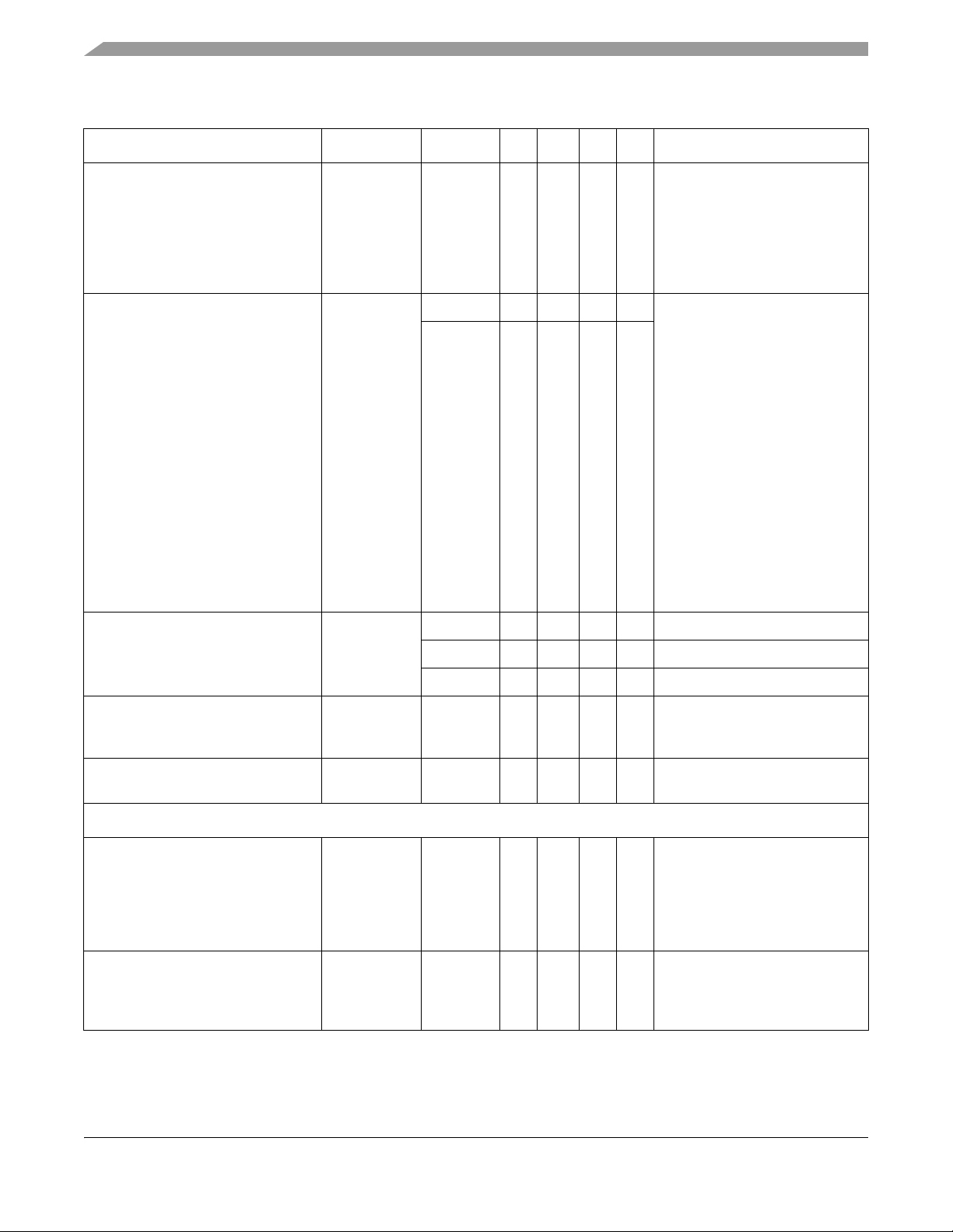
The i.MX 8QuadMax processor offers numerous advanced features as shown in this table.
Table 1. i.MX 8QuadMax advanced features
Function Feature
Multicore architecture provides
4× Cortex-A53, 2× Cortex-A72 cores,
and 2× Cortex-M4F cores
Graphics Processing Unit (GPU) 16× Vec4 shaders with 64 execution units. Split GPU architecture allows for dual
Video Processing Unit (VPU) H.264 decode (4Kp30)
AArch64 for 64-bit support and new architectural features
AArch32 for full backward compatibility with ARMv7
Cortex-A72 and Cortex-A53 cores support ARM virtualization extensions. sMMU
provides address virtualization to all subsystems.
Cortex-M4F cores for real-time applications
independent 8-Vec4 shader GPUs or a combined 16-Vec4 shader GPU.
Supports OpenGL 3.0, 2.1,; OpenGL ES 3.2, 3.1 (with AEP), 3.0, 2.0, and 1.1;
OpenCL 1.2 Full Profile and 1.1; OpenVG 1.1; and Vulkan
High-performance 2D Blit Engine
H.265 decode (4Kp60)
WMV9/VC-1 imple decode
MPEG 1 and 2 decode
AVS decode
MPEG4.2 ASP, H.263, Sorenson Spark decode
Divx 3.11 including GMC decode
ON2/Google VP6/VP8 decode
RealVideo 8/9/10 decode
JPEG and MJPEG decode
2× H.264 encode (1080p30)
Tensilica HiFi 4 DSP for pre- and
post-processing
Memory 64-bit LPDDR4 @1600 MHz
i.MX 8QuadMax Automotive and Infotainment Applications Processors, Rev. 1, 12/2020
666 MHz
Fixed-point and vector-floating-point support
32 KB instruction cache, 48 KB data cache, 512 KB SRAM (448 KB of OCRAM and
64 KB of TCM)
1× Quad SPI which can be used to connect to an FPGA
2× Quad SPI or 1× Octal SPI (FlexSPI) for fast boot from SPI NOR flash
2× SD 3.0 card interfaces
1× eMMC5.1/SD3.0
RAW NAND (62-bit ECC support via BCH-62 module)
NXP Semiconductors2
Page 3
Introduction
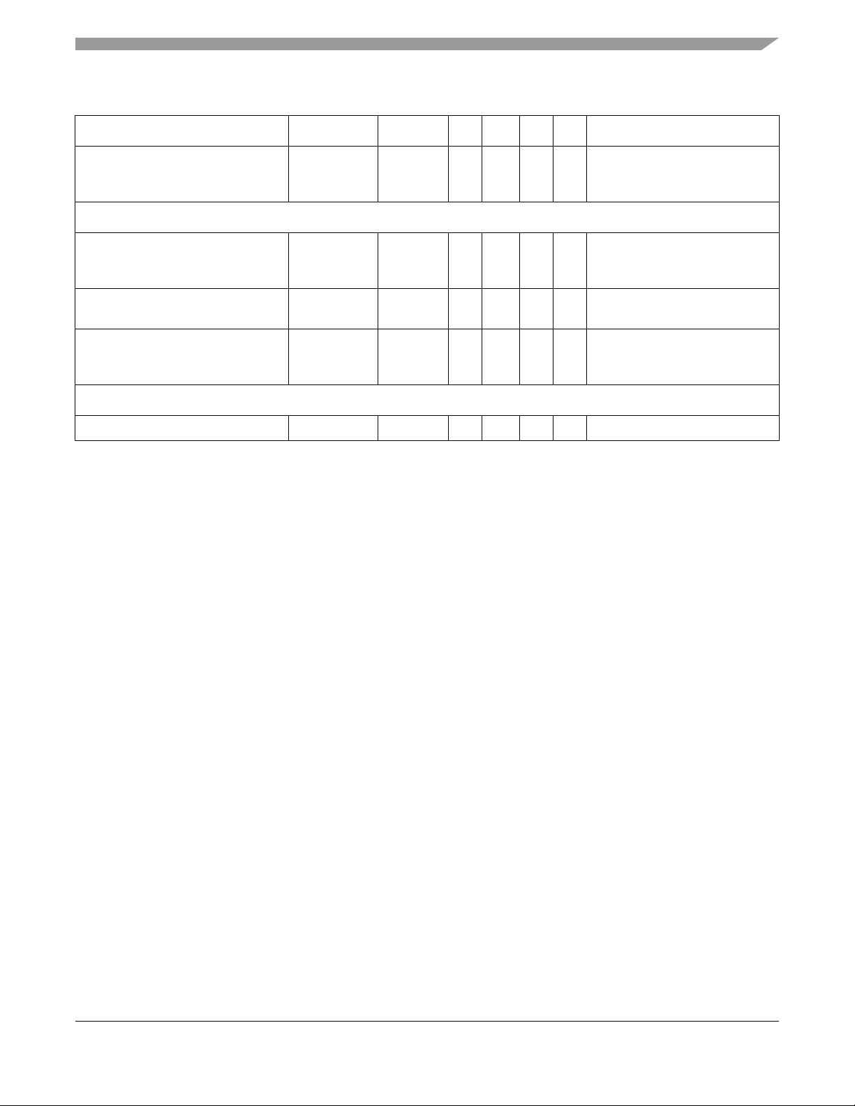
Table 1. i.MX 8QuadMax advanced features (continued)
Function Feature
Display Controller Supports single UltraHD 4Kp60 display or up to 4 independent FullHD 1080p60
displays
Up to 18-layer composition
Complementary 2D blitting engines and online warping functionality
Integrated Failover Path (SafeAssure) to ensure display content stays valid even in
event of a software failure
Display I/O 2× MIPI-DSI with 4 lanes each
1× HDMI-TX/DisplayPort compliant with:
• HDMI 1.4b and 2.0a
•eDP 1.4
•DP 1.3
2× LVDS Tx with 2 channels of 4 lanes each
Camera I/O and video 2× MIPI-CSI with 4-lanes each, MIPI DPHYSM v1.1
Security Advanced High Assurance Boot (AHAB) secure & encrypted boot
Random Number Generator with a high-quality entropy source generator and
Hash_DRBG (based on hash functions)
RSA up to 4096, Elliptic Curve up to 1023
AES-128/192/256, DES, 3DES, MD5, SHA-1, SHA-224/256/384/512
Dedicated Security Controller for Flashless SHE and HSM support, Trustzone, RTIC
Built-in ECDSA/DSA protocol support
See the security reference manual for this chip for a full list of security features.
System Control • 2× I
• The tightly coupled M4 I2C ports cannot be used for general-purpose use
• System Control Unit (SCU):
• Power control, clocks, reset
• Boot ROMs
• PMIC interface
• Resource Domain Controller
2
C tightly coupled with Cortex-M4 cores (1× per Cortex M4F core)
i.MX 8QuadMax Automotive and Infotainment Applications Processors, Rev. 1, 12/2020
NXP Semiconductors 3
Page 4
Introduction
Table 1. i.MX 8QuadMax advanced features (continued)
Function Feature
I/O 1× PCIe (2-lanes). Can be used as two PCIe 3.0 controllers with one-lane,
independent operation. PCIe 1.0 and 2.0 compliant. PCIe 3.0 capable, contact your
NXP representative.
1× USB 3.0 with PHY
2× USB 2.0 (1 with PHY, 1 with HSIC)
1× SATA 3.0 can be used as PCIe one-lane. This is in addition to the standard PCIe
controller. PCIe 1.0 and 2.0 compliant. PCIe 3.0 capable, contact your NXP
representative.
2× 1Gb Ethernet with AVB (can be used as 10/100 Mbps ENET with AVB)
3× CAN/CAN-FD
8× UARTs:
•5× UARTs (2× with hardware flow control)
•2× UARTs tightly coupled with Cortex-M4F cores (1× per Cortex-M4F core)
•1× UART tightly coupled with SCU
2
C:
18× I
•5× General-Purpose I2C (full-speed with DMA support)
• Low-speed I
•2× master I2C in MIPI-DSI (1× per instance)
•4× master I2C in LVDS (2× per instance)
•2× master I
•2× master I2C in MIPI-CSI (1× per instance)
Note: Although low-speed I2Cs can be made available for general purpose use
which requires the associated PHY (for example, MIPI) to be powered on, it is not
recommended.
Note: I/O muxing constraints prevent using all I
• 2x I2C tightly coupled with Cortex-M4 cores (1x per Cortex M4F core)
Note: The tightly coupled M4 I2C ports cannot be used for general purpose use.
2
C tightly coupled with SCU for communication with the PMIC. Not general
•1× I
purpose and not available for non-PMIC uses.
2
C without DMA support:
2
C in HDMI-TX
2
Cs simultaneously.
4× SAI (SAI0 and SAI1 are transmit/receive; SAI2 and SAI3 are receive only)
2× Enhanced Serial Audio Interface (ESAI)
× ASRC (Asynchronous Sample Rate Converter) (note: no I/O signals are directly
connected to this module)
1× SPDIF (Tx and Rx)
2× 4-channel ADC converters
3.3 V/1.8 V GPIO
4× PWM channels
1× 6×8 KPP (Key Pad Port)
1× MQS (Medium Quality Sound)
4× SPI
Packaging Case FCPBGA 29 x 29 mm, 0.75 mm pitch
i.MX 8QuadMax Automotive and Infotainment Applications Processors, Rev. 1, 12/2020
NXP Semiconductors4
Page 5
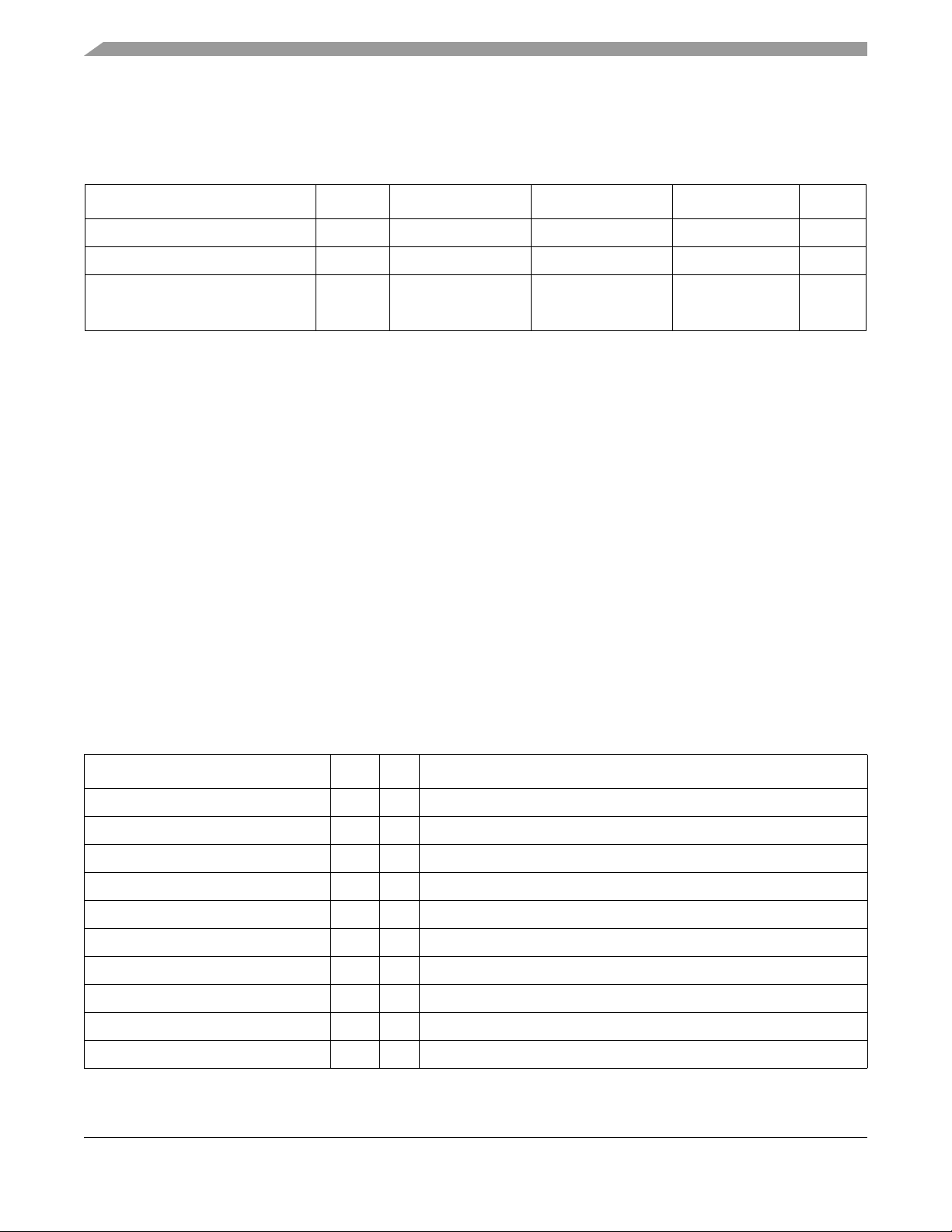
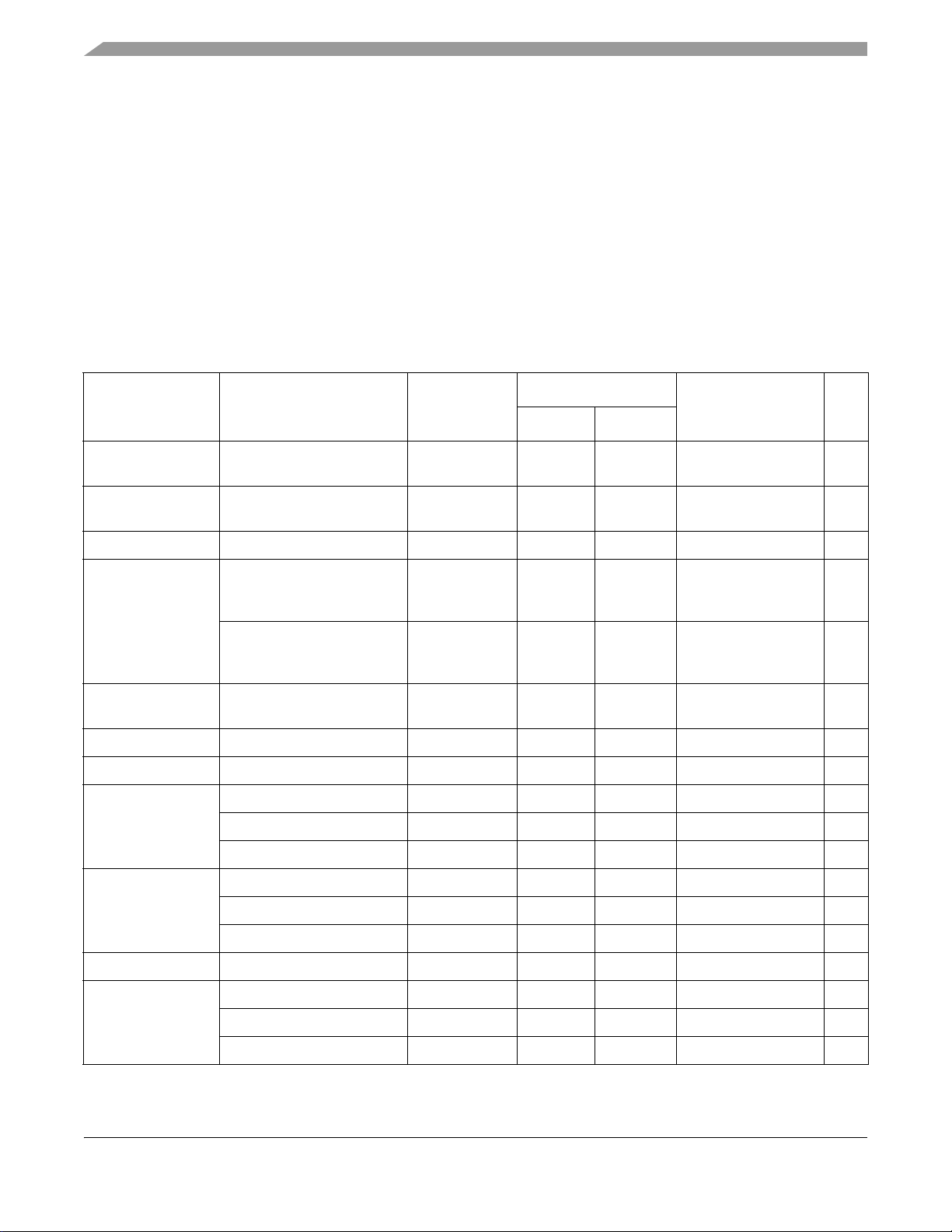
1.1 Ordering Information
For ordering information, contact an NXP representative at nxp.com.
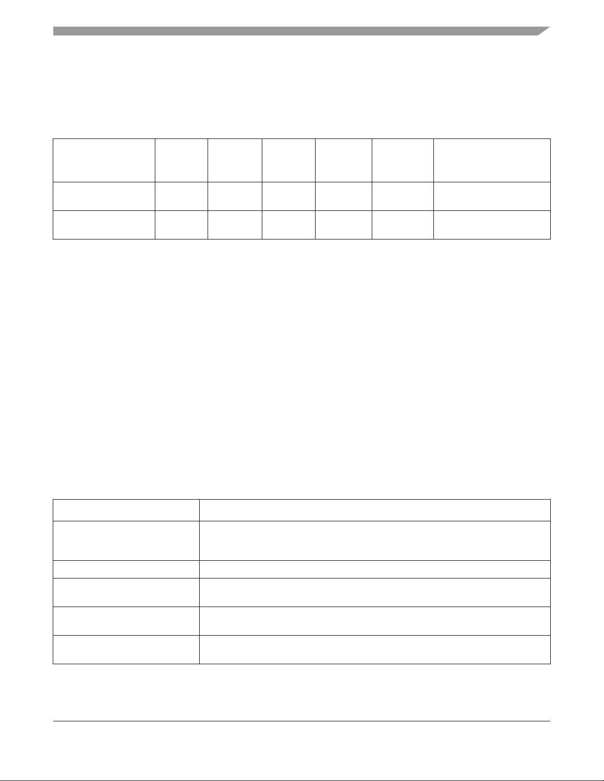
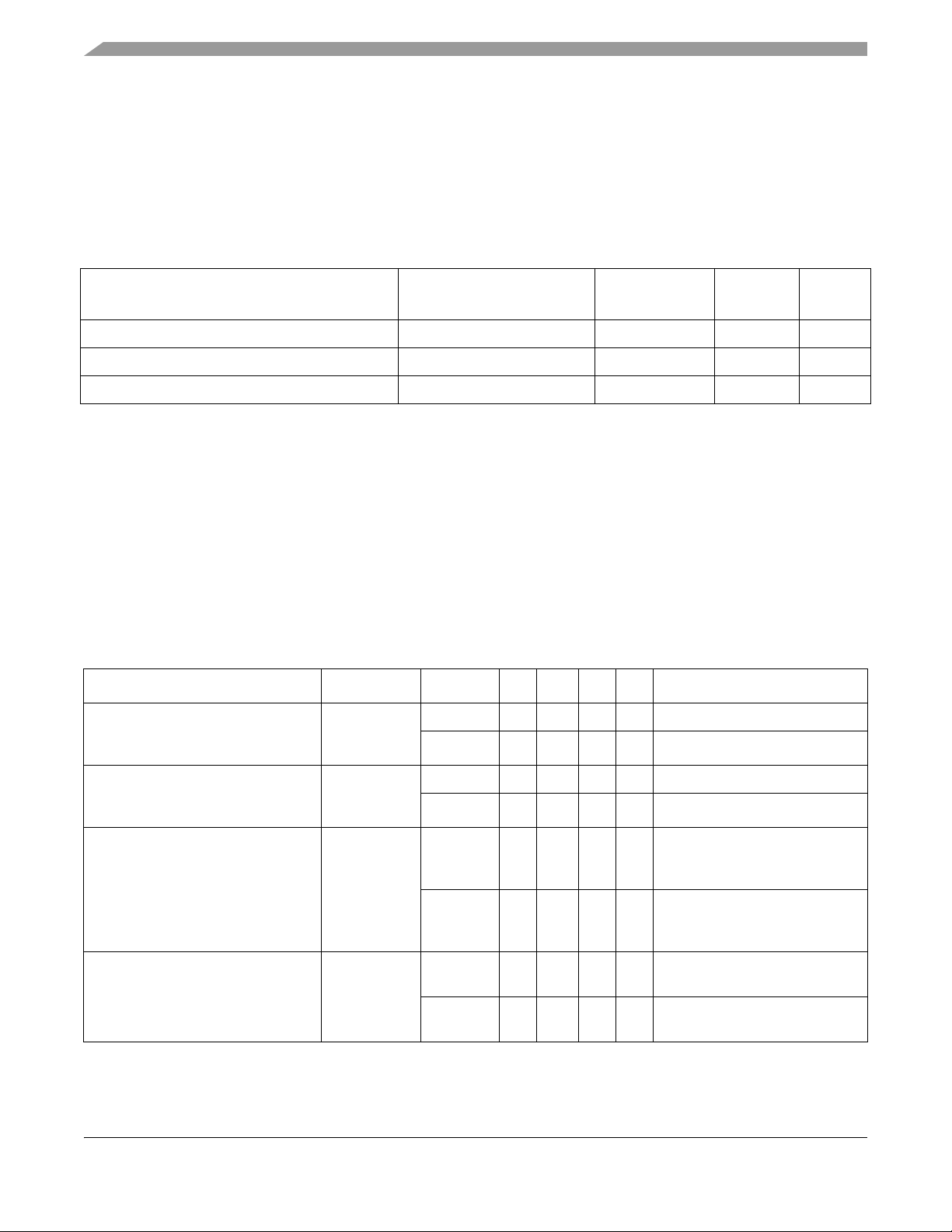
Table 2. i.MX 8QuadMax Orderable part numbers
Introduction
Part Number Options
MIMX8QM5AVUFFAB With VPU,
GPU
MIMX8QM6AVUFFAB With VPU,
GPU, DSP
Cortex-A72
Speed
Grade
1.6 GHz 1.20 GHz 264 MHz Automotive 29 mm
1.6 GHz 1.20 GHz 264 MHz Automotive 29 mm × 29 mm, 0.75 mm
Cortex-A53
Speed
Grade
Cortex-M4F
Speed
Grade
Tem per atur e
Grade
Package
× 29 mm, 0.75 mm
pitch, FCPBGA (lidded)
pitch, FCPBGA (lidded)
1.2 System Controller Firmware (SCFW) Requirements
The i.MX 8 and 8X families require a minimum SCFW release version for correct operation and to prevent
potential reliability issues.
The SCFW is released as part of a Board Support Package (e.g. Linux, Android) which may vary in version
number for a specific BSP.
For example, NXP Yocto Linux release 5.4.47_2.2.0 GA contains SCFW version 1.6.0, whereas NXP
Yocto Linux release 5.4.47_2.2.0 GA contains SCFW version 1.6.0.
The released SCFW version associated within each BSP is the minimum version required to correctly
support the wider BSP functionality.
Customers should always check that they are using the specific SCFW binary delivered within their chosen
BSP release. Customers should not mix newer BSP versions with older revisions of the SCFW.
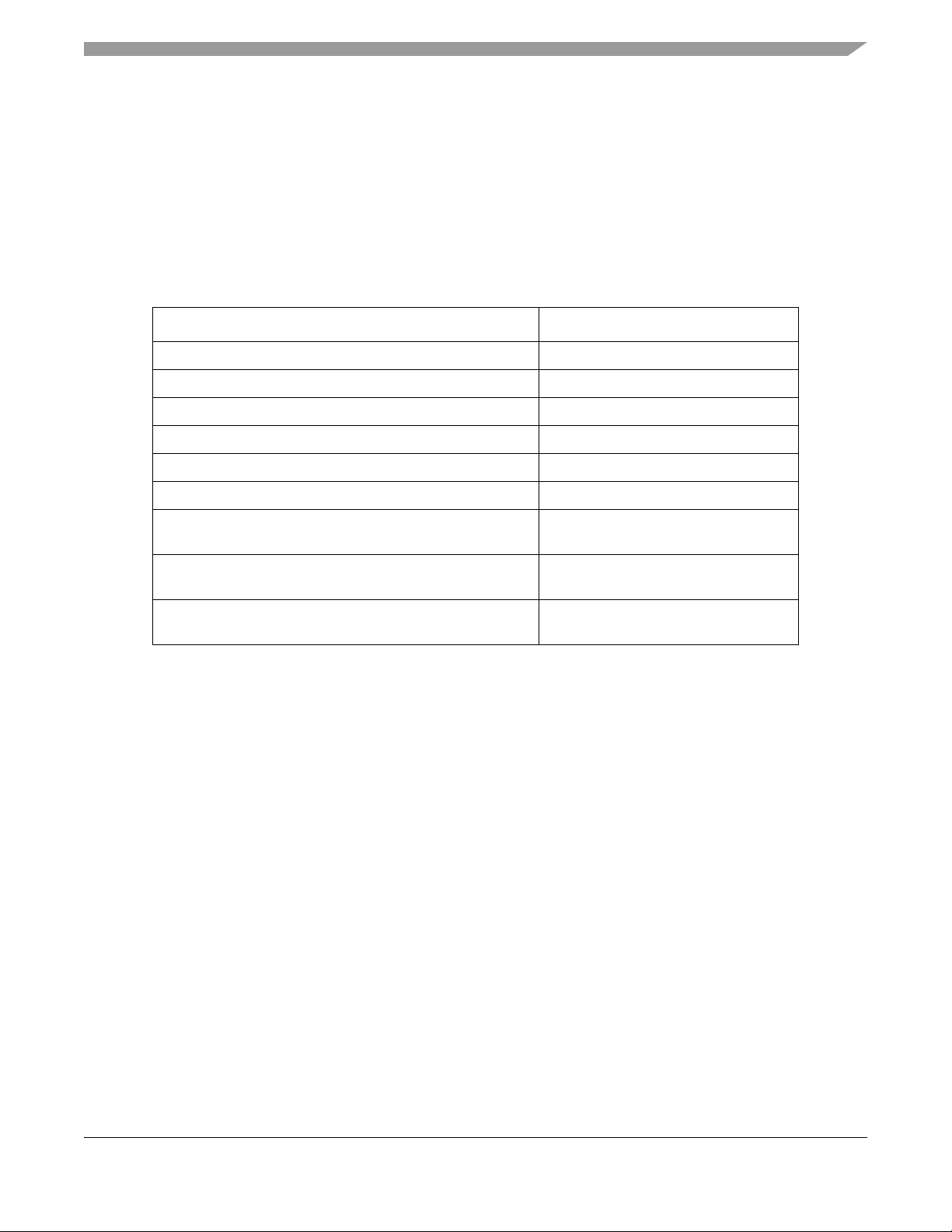
1.3 Related resources
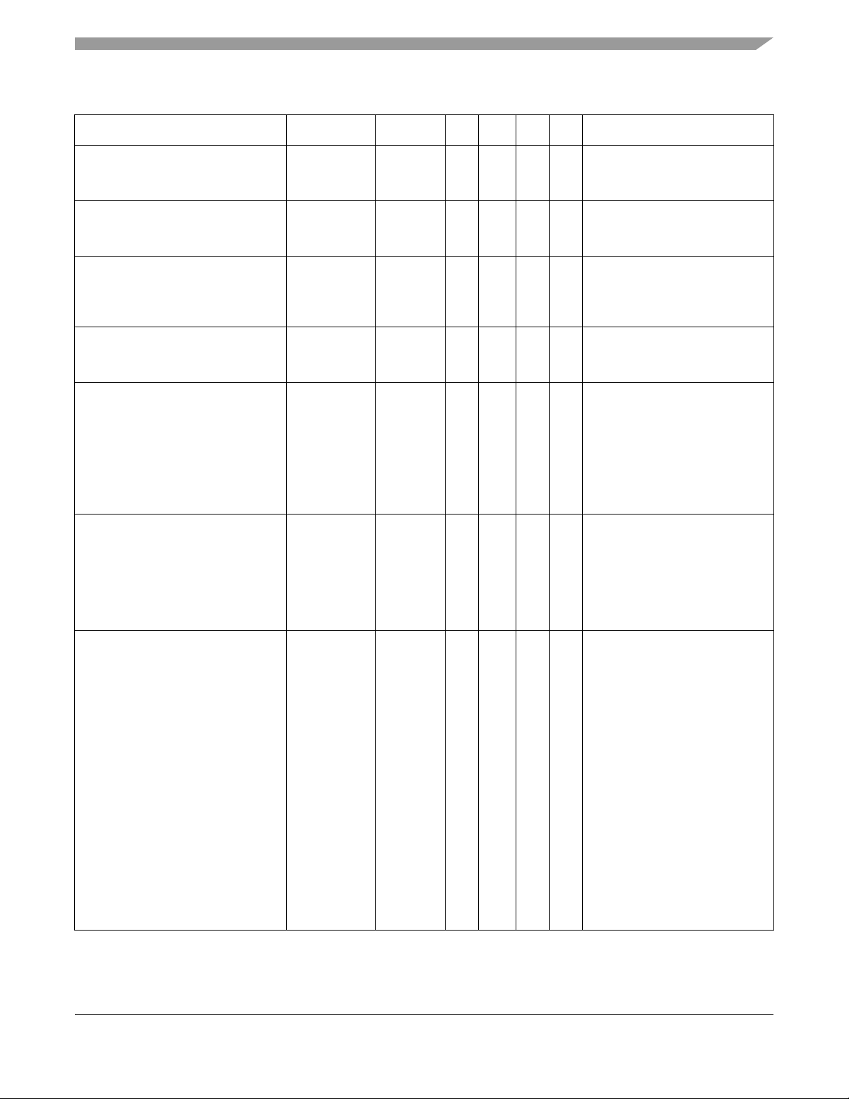
Table 3. Related resources
Type Description
Reference manual The i.MX 8QuadMax Applications Processor Reference Manual (IMX8DQXPRM)
contains a comprehensive description of the structure and function (operation) of the
SoC.
Data sheet This data sheet includes electrical characteristics and signal connections.
Chip Errata The chip mask set errata provides additional and/or corrective information for a particular
device mask set.
Package drawing Package dimensions are provided in Section 6, “Package information and contact
assignments".”
Hardware guide The i.MX 8QuadMax/8QuadPlus Hardware Developer’s Guide provides system design
guidelines.
i.MX 8QuadMax Automotive and Infotainment Applications Processors, Rev. 1, 12/2020
NXP Semiconductors 5
Page 6

Architectural Overview
2 Architectural Overview
The following subsections provide an architectural overview of the i.MX 8QuadMax processor system.
i.MX 8QuadMax Automotive and Infotainment Applications Processors, Rev. 1, 12/2020
NXP Semiconductors6
Page 7
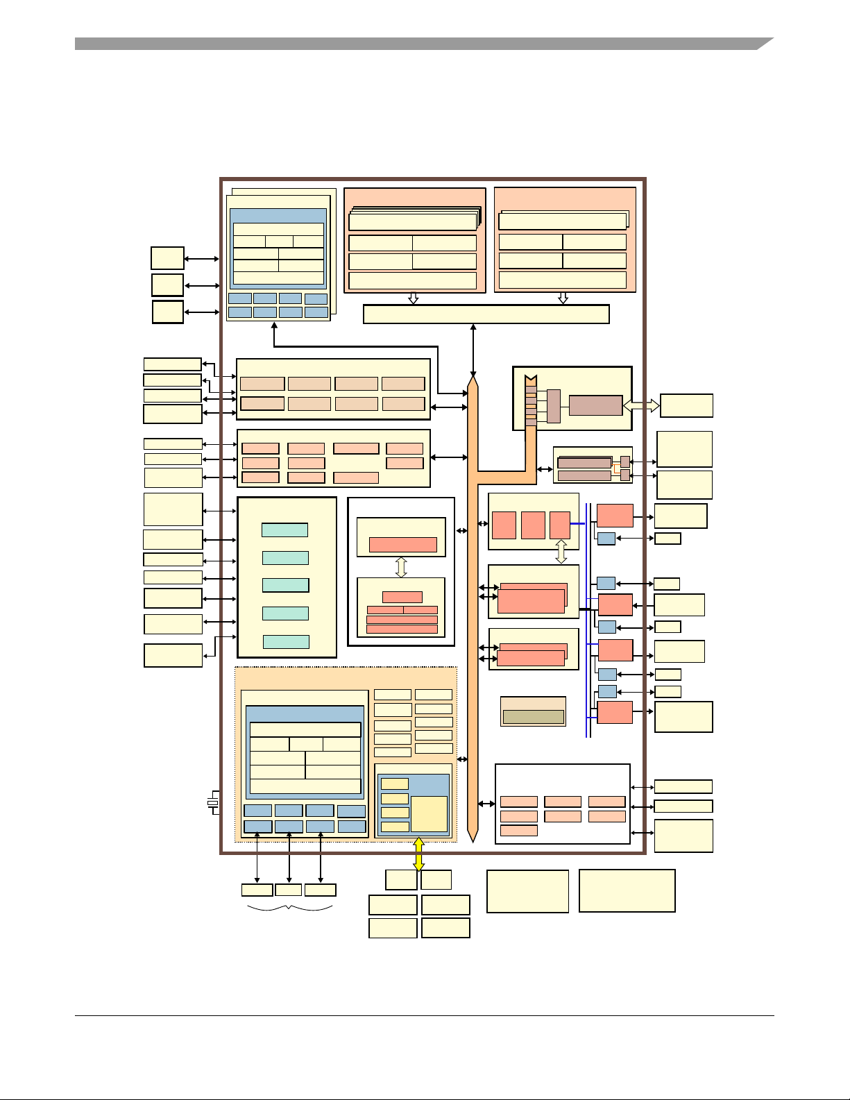
2.1 Block Diagram
VFP
1MB L2 w/ ECC
32KB D$
NEON
32KB I$
4x ARM Cortex-A53
CPU1 Platform
VFP
1MB L2 w/ optional ECC
32KB D$
NEON
48KB I$
2x ARM Cortex-A72
CPU2 Platform
RNG
Ciphers
(ECC, RSA)
Secure RTC
Tamper
Detection
Secure
JTAG
64k Secure
RAM
ADC
(4 channels each)
CAN / CAN-FD
I2C w/ DMA
UART (5 Mb/s)
32-bit GPIO
24M and 32k
XTALOSC
Sources
System Control Unit
Clock, Reset
IOMUX
OTP
ADM
SNVS
CAAM
Security
256KB TCM w/ ECC
16KB system$
MMCAU
16KB code$
MCM
nvic
fpu mpu
M4 CPU
M4 Platform
SCU CM4 Complex
Debug
DAP, CTI, etc
SJC
Boot ROM
RDC
Power Mgmt
PWM
PMIC I/F
2x MU
INTs
WDOG
RGPIO
LPUART
LPI2C
LPIT
HAB
Tempmon
2x ADC
5x LPUART
5x LPI2C
4x LPSPI
2x eDMA
3x FlexCAN
DMA Subsystem
Audio Subsystem
2x LVDS
TX
2x MIPI
CSI2
Display Controllers
Imaging
ISI
MJPEG
ENC
MJPEG
DEC
Video Processing Unit
VPU
DSP Core
HIFI4 DSP
32KB I$ 48KB D$
64KB TCM
448KB OCRAM
HDMI
LPI2C
LPI2C
LPI2C
External Memory Interface
DDR
Controller
BN
PG
PG
PG
Graphics Processing Unit
1x I2C
1x UART
1x GPIO
Dedicated
1x eMMC
5.1 / SD 3.0
1x USB 3.0 PHY
6x8 Keypad
2x SD 3.0 (UHS-I)
1x USB 2.0
Host / HSIC
10/100/1000M
Ethernet + AVB
64-bit LPDDR4
@1600 MHz
RAW /
ONFI 3.2
NAND Flash
2x Quad SPI /
1x Octal SPI
NOR Flash
Mult-format Decode
H.265 Dec (4k60)
H.264 Dec (1080p60)
H.264 Enc (1080p30)
Dual Core, 16 shaders
Vulkan, OGLES 3.2 w/ AEP,
OCL 2.0, VG 1.1
2D Blit Engine
2x MIPI CSI2
(4-lanes)
1/2 LVDS TX
(4 lanes each)
1x I2C
1x I2C
HDMI Tx 2.0a
(eDP 1.4
DisplayPort 1.3)
1x I2C
SPDIF TX / RX
2x SAI TX / RX
2x SAI RX
ESAI TX / RX
SSI Bus
PG
2x User CM4 Complexes
256KB TCM w/ ECC
16KB system$
MMCAU
16KB code$
MCM
nvic
fpu mpu
M4 CPU
M4 Platform
PWM
2x MU
INTs
WDOG
RGPIO
LPUART
LPI2C
LPIT
1x I2C
(each)
1x UART
(each)
1x GPIO
(each)
Cache Coherent Interconnect (CCI-400)
2x DPU (4x LCD)
2x GPU
2x MIPI
DSI
LPI2C
MIPI Display
(4-lanes)
1x I2C
SATA
High Speed I/O
PHYPHY
2x PCIe
1x SATA 3.0 /
1x PCIe
(1 lane)
x1 PCIe
2 lanes /
x2 PCIe
1 lane each
1x USB 2.0
OTG, PHY
Connectivity Subsystem
USB3
2x USB2
3x uSDHC
2x ENET
NAND
2x EVM SIM
2x FTM
LPI2C
1x I2C
Security
Controller
(M0+)
SECO
2x ESAI
2x ASRC
8x SAI
MQS
SPDIF
6x GPT
HDMI TX SAI
2x eDMA
ACM
Audio Mixer
OCRAM (256KB)
Internal Memory
Low Speed I/O
(LSIO) Subsystem
14x MU
IEE
5x GPT
4x PWM
KPP
2x FlexSPI
8x GPIO
VPU Subsystem
The following figure shows the functional modules in the processor system.
Architectural Overview
Figure 1. i.MX 8QuadMax System Block Diagram
i.MX 8QuadMax Automotive and Infotainment Applications Processors, Rev. 1, 12/2020
NXP Semiconductors 7
Page 8
Modules List
3 Modules List
The i.MX 8QuadMax processors contain a variety of digital and analog modules. This table describes the
processor modules in alphabetical order.
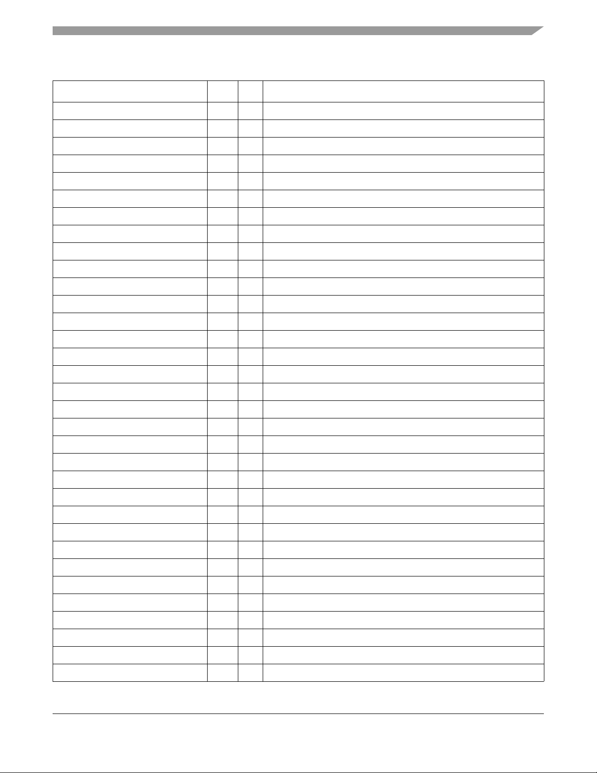
Table 4. i.MX 8QuadMax modules list
Block
Mnemonic
ADC Analog-to-Digital
APBH-DMA NAND Flash and BCH
A53 Arm (CPU1) CPU cluster embedding 4x Cortex-A53 CPUs with a 32KB L1 instruction cache and
A72 Arm (CPU2) CPU cluster embedding 2x Cortex-A72 CPUs with a 48 KB L1 instruction cache
ASRC Asynchronous Sample
BCH-62 Binary-BCH ECC
CAAM Cryptographic
Block Name Brief Description
The analog-to-digital converter (ADC) is a successive approximation ADC
Converter
ECC DMA Controller
Rate Converter
Processor
Accelerator and
Assurance Module
designed for operation within a SoC.
The AHB-to-APBH bridge provides the chip with a peripheral attachment bus
running on the AHB's HCLK, which includes the AHB-to-APB PIO bridge for a
memory-mapped I/O to the APB devices, as well as a central DMA facility for
devices on this bus and a vectored interrupt controller for the Arm core.
a 32KB data cache. The CPUs share a 1 MB L2 cache.
and 32 KB data cache. The CPUs have a 1MB L2 cache.
The Asynchronous Sample Rate Converter (ASRC) converts the sampling rate of
a signal associated to an input clock into a signal associated to a different output
clock. The ASRC supports concurrent sample rate conversion of up to 10 channels
of about -120dB THD+N. The sample rate conversion of each channel is
associated to a pair of incoming and outgoing sampling rates. The ASRC supports
up to three sampling rate pairs.
The BCH62 module provides up to 62-bit ECC for NAND Flash controller (GPMI2)
CAAM is a cryptographic accelerator and assurance module. CAAM implements
several encryption and hashing functions, a run-time integrity checker, and a
Pseudo Random Number Generator (PRNG).
CAAM also implements a Secure Memory mechanism. In this device the security
memory provided is 64 KB.
CTI Cross Trigger Interface CTI sends signals across the chip indicating that debug events have occurred. It is
used by features of the Coresight infrastructure.
CTM Cross Trigger Matrix Cross Trigger Matrix IP is used to route triggering events between CTIs.
DAP Debug Access Port The DAP provides real-time access for the debugger without halting the core to:
• System memory and peripheral registers
• All debug configuration registers
The DAP also provides debugger access to JTAG scan chains.
DC Display Controller Dual display controller
DDR Controller DRAM Controller • Memory types: LPDDR4
• Two channels of 32-bit memory:
• LPDDR4 up to 1.6 GHz
i.MX 8QuadMax Automotive and Infotainment Applications Processors, Rev. 1, 12/2020
NXP Semiconductors8
Page 9
Table 4. i.MX 8QuadMax modules list (continued)
Modules List
Block
Mnemonic
DPR Display/Prefetch/
eDMA Enhanced Direct
Block Name Brief Description
Resolve
Memory Access
The DPR prefetches data from memory and converts the data to raster format for
display output. Raster source buffers can also be prefetched unconverted. The
resolve process supports graphics and video formatted tile frame buffers and
converts them to raster format. Embedded display memory is used as temporary
storage for data which is sourced by the display controller to drive the display.
•4× eDMA with a total of 128 channels (note: all channels are not assigned; see
the product reference manual for more information):
•4× instances with 32 channels each
• Programmable source, destination addresses, transfer size, plus support for
enhanced addressing modes
• Internal data buffer, used as temporary storage to support 64-byte burst
transfers, one outstanding transaction per DMA controller.
• Transfer control descriptor organized to support two-deep, nested transfer
operations
• Channel service request via one of three methods:
• Explicit software initiation
• Initiation via a channel-to-channel linking mechanism for continuous
transfers
• Peripheral-paced hardware requests (one per channel)
• Support for fixed-priority and round-robin channel arbitration
• Channel completion reported via interrupt requests
• Support for scatter/gather DMA processing
• Support for complex data structures via transfer descriptors
• Support to cancel transfers via software or hardware
• Each eDMA instance can be uniquely assigned to a different resource domain,
security (TZ) state, and virtual machine
• In scatter-gather mode, each transfer descriptor’s buffers can be assigned to
different SMMU translation
ENET Ethernet Controller 2× 1 Gbps Ethernet controllers supporting RGMII + AVB (Audio Video Bridging,
IEEE 802.1Qav)
ESAI Enhanced Serial Audio
Interface
FTM FlexTimer Provides input signal capture and PWM support
FlexCAN Flexible Controller Area
Network
i.MX 8QuadMax Automotive and Infotainment Applications Processors, Rev. 1, 12/2020
The Enhanced Serial Audio Interface (ESAI) provides a full-duplex serial port for
serial communication with a variety of serial devices, including industry-standard
codecs, SPDIF transceivers, and other processors. The ESAI consists of
independent transmitter and receiver sections, each section with its own clock
generator. All serial transfers are synchronized to a clock. Additional
synchronization signals are used to delineate the word frames. The normal mode
of operation is used to transfer data at a periodic rate, one word per period. The
network mode is also intended for periodic transfers; however, it supports up to 32
words (time slots) per period. This mode can be used to build time division
multiplexed (TDM) networks. In contrast, the on-demand mode is intended for
non-periodic transfers of data and to transfer data serially at high speed when the
data becomes available.
The ESAI has 12 pins for data and clocking connection to external devices.
Communication controller implementing the CAN with Flexible Data rate (CAN FD)
protocol and the CAN protocol according to the CAN 2.0B protocol specification.
NXP Semiconductors 9
Page 10
Modules List
Table 4. i.MX 8QuadMax modules list (continued)
Block
Mnemonic
FlexSpi (Quad
SPI/Octal SPI)
GIC Generic Interrupt
GPIO General Purpose I/O
GPMI General Purpose Media
GPT General Purpose Timer Each GPT is a 32-bit “free-running” or “set and forget” mode timer with
Block Name Brief Description
Flexible Serial
Peripheral Interface
Controller
Modules
Interface
• Flexible sequence engine to support various flash vendor devices, including
HyperBus™ devices:
• Support for FPGA interface
• Single, dual, quad, and octal mode of operation.
• DDR/DTR mode wherein the data is generated on every edge of the serial flash
clock.
• Support for flash data strobe signal for data sampling in DDR and SDR mode.
• Two identical serial flash devices can be connected and accessed in parallel for
data read operations, forming one (virtual) flash memory with doubled readout
bandwidth.
The GIC-500 handles all interrupts from the various subsystems and is ready for
virtualization.
Used for general purpose input/output to external devices. Each GPIO module
supports 32 bits of I/O.
The GPMI module supports up to 8
encryption/decryption for NAND Flash controller (GPMI). The GPMI supports
separate DMA channels per NAND device.
programmable prescaler and compare and capture register. A timer counter value
can be captured using an external event and can be configured to trigger a capture
event on either the leading or trailing edges of an input pulse. When the timer is
configured to operate in “set and forget” mode, it is capable of providing precise
interrupts at regular intervals with minimal processor intervention. The counter has
output compare logic to provide the status and interrupt at comparison. This timer
can be configured to run either on an external clock or on an internal clock.
× NAND devices. 62-bit ECC (BCH)
GPU Graphics Processing 2× GC7000XSVX GPUs with 8 shaders each that can run either independently or
in “dual-mode” with 16 shaders.
HDMI Tx/
DP/eDP
HiFi 4 DSP Audio Processor A highly optimized audio processor geared for efficient execution of audio and
2
CI
I
IEE • Supports direct encryption and decryption of FlexSPI memory type
IOMUXC IOMUX Control This module enables flexible I/O multiplexing. Each I/O pad has default and several
JPEG/dec MJPEG engine for
HDMI Tx interface HDMI transmitter, Display Port 1.3 and embedded Display Port 1.4
voice codecs and pre- and post-processing modules to offload the Arm core.
2
C Interface I2C provides serial interface for external devices.
• Provides decryption services (lower performance) for DRAM traffic
• Supports I/O direct encrypted storage and retrieval
• Support for a number of cryptographic standards:
• 128/256-bit AES Encryption (AES-CTR, AES-XTS mode options)
• Multiple keys supported:
• Loaded via secure key channel from security block
• Key selection is per access and based on source of transaction
alternate functions. The alternate functions are software configurable.
Provides up to 4-stream decoding in parallel.
decode
i.MX 8QuadMax Automotive and Infotainment Applications Processors, Rev. 1, 12/2020
NXP Semiconductors10
Page 11
Table 4. i.MX 8QuadMax modules list (continued)
Modules List
Block
Mnemonic
JPEG/enc MJPEG engine for
KPP Key Pad Port The Keypad Port (KPP) is a 16-bit peripheral that can be used as a 6 x 8 keypad
LPIT-1
LPIT-2
LPSPI 0–3 Configurable SPI Full-duplex enhanced Synchronous Serial Interface. It is configurable to support
LVDS LVDS Display Bridge
M4F Arm (CPU3) • Cortex-M4F core
Block Name Brief Description
Provides up to 4-stream encoding in parallel.
encode
matrix interface or as general purpose input/output (I/O).
Low-Power Periodic
Interrupt Timer
Each LPIT is a 32-bit “set and forget” timer that starts counting after the LPIT is
enabled by software. It is capable of providing precise interrupts at regular intervals
with minimal processor intervention. It has a 12-bit prescaler for division of input
clock frequency to get the required time setting for the interrupts to occur, and
counter value can be programmed on the fly.
Master/Slave modes, four chip selects to support multiple peripherals.
The LVDS is a high performance serializer that interfaces with LVDS
displays
• AHB LMEM (Local Memory Controller) including controllers for TCM and cache
• 256 KB embedded tightly coupled memory(TCM) (128 KB TCMU, 128 KB
• 16 KB Code Bus Cache
• 16 KB System Bus Cache
• ECC for TCM memories and parity for code and system caches
• Integrated Nested Vector Interrupt Controller (NVIC)
• Wakeup Interrupt Controller (WIC)
• FPU (Floating Point Unit)
• Core MPU (Memory Protection Unit)
• Support for exclusive access on the system bus
• MMCAU (Crypto Acceleration Unit)
• MCM (Miscellaneous Control Module)
.
memories
TCML)
MIPI CSI-2 MIPI CSI-2 Interface The MIPI CSI-2 IP provides MIPI CSI-2 standard camera interface ports. The MIPI
CSI-2 interface supports up to 1.5 Gbps for up to 4 data lanes
MIPI-DSI MIPI DSI interface The MIPI DSI IP provides DSI standard display serial interface. The DSI interface
supports 80 Mbps to 1.5 Gbps speed per data lane.
MQS Medium Quality Sound Medium Quality Sound (MQS) is used to generate 2-channel medium quality
PWM-like audio via two standard digital GPIO pins.
OCOTP_CTRL OTP Controller The On-Chip OTP controller (OCOTP_CTRL) provides an interface for reading,
programming, and/or overriding identification and control information stored in
on-chip fuse elements. The module supports electrically-programmable poly fuses
(eFUSEs). The OCOTP_CTRL also provides a set of volatile software-accessible
signals that can be used for software control of hardware elements, not requiring
non-volatility. The OCOTP_CTRL provides the primary user-visible mechanism for
interfacing with on-chip fuse elements. Among the uses for the fuses are unique
chip identifiers, mask revision numbers, cryptographic keys, JTAG secure mode,
boot characteristics, and various control signals requiring permanent nonvolatility.
i.MX 8QuadMax Automotive and Infotainment Applications Processors, Rev. 1, 12/2020
NXP Semiconductors 11
Page 12
Modules List
Table 4. i.MX 8QuadMax modules list (continued)
Block
Mnemonic
OCRAM On-Chip Memory
PCIe PCI Express PCIe 1.0 and 2.0 compliant. PCIe 3.0 capable; contact your NXP representative. .
PRG Prefetch/Resolve
PWM Pulse Width Modulation The pulse-width modulator (PWM) has a 16-bit counter and is optimized to
RAM
64 KB Secure
RAM
RAM
256 KB
RNG Random Number
Block Name Brief Description
The On-Chip Memory controller (OCRAM) module is designed as an interface
Controller
Gasket
Secure/non-secure
RAM
Internal RAM Internal RAM, which is accessed through OCRAM memory controllers.
Generator
between the system’s AXI bus and the internal (on-chip) SRAM memory module.
The OCRAM is used for controlling the 256 KB multimedia RAM through a 64-bit
AXI bus.
The PRG is a gasket which translates system memory accesses to local display
RTRAM accesses for display refresh. It works with the DPR to complete the
prefetch and resolving operations needed to drive the display.
generate sound from stored sample audio images and it can also generate tones.
It uses 16-bit resolution and a 4×16 data FIFO to generate square waveforms.
Secure/non-secure Internal RAM, interfaced through the CAAM.
The purpose of the RNG is to generate cryptographically strong random data. It
uses a true random number generator (TRNG) and a pseudo-random number
generator (PRNG) to achieve true randomness and cryptographic strength. The
RNG generates random numbers for secret keys, per message secrets, random
challenges, and other similar quantities used in cryptographic algorithms.
SAI I2S/SSI/AC97 Interface The SAI module provides a synchronous audio interface that supports full duplex
serial interfaces with frame synchronization, such as I2S, AC97, TDM, and
codec/DSP interfaces.
SECO Security Controller Core and associated memory and hardware responsible for key management.
SJC Secure JTAG Controller The SJC provides the JTAG interface, which is compatible with JTAG TAP
standards, to internal logic. This device uses JTAG port for production, testing, and
system debugging. Additionally, the SJC provides BSR (Boundary Scan Register)
standard support, which is compatible with IEEE1149.1 and IEEE1149.6 standards.
The JTAG port must be accessible during platform initial laboratory bring-up, for
manufacturing tests and troubleshooting, as well as for software debugging by
authorized entities. The SJC incorporates three security modes for protecting
against unauthorized accesses. Modes are selected through eFUSE configuration.
sMMU System MMU The System MMU is an MMU-500 from Arm. It supports two-stage address
translation and multiple translation contexts.
SNVS Secure Non-Volatile
Storage
SPDIF Sony Philips Digital
Interconnect Format
Secure Non-Volatile Storage, including Secure Real Time Clock, Security State
Machine, Master Key Control.
The Sony/Philips Digital Interface (SPDIF) audio block is a stereo transceiver that
allows the processor to receive and transmit digital audio. The SPDIF transceiver
allows the handling of both SPDIF channel status (CS) and User (U) data and
includes a frequency measurement block that allows the precise measurement of
an incoming sampling frequency.
i.MX 8QuadMax Automotive and Infotainment Applications Processors, Rev. 1, 12/2020
NXP Semiconductors12
Page 13

Table 4. i.MX 8QuadMax modules list (continued)
Modules List
Block
Mnemonic
TEMPMON Temperature Monitor The temperature monitor/sensor IP module for detecting high temperature
UART UART Interface • High-speed TIA/EIA-232-F compatible, up to 5.0 Mbps
USB3/USB2 The USB3/USB2 OTG module has been specified to perform USB 3.0 dual role and
Block Name Brief Description
conditions. The temperature read out does not reflect case or ambient temperature.
It reflects the temperature in proximity of the sensor location on the die.
Temperature distribution may not be uniformly distributed; therefore, the read-out
value may not be the reflection of the temperature value for the entire die.
• Serial IR interface low-speed, IrDA-compatible (up to 115.2 Kbit/s)
• 9-bit or Multidrop mode (RS-485) support (automatic slave address detection)
• 7, 8, 9, or 10-bit data characters (7-bits only with parity)
• 1 or 2 stop bits
• Programmable parity (even, odd, and no parity)
• Hardware flow control support for request to send (RTS_B) and clear to send
(CTS_B) signals
USB 2.0 On-The-Go (OTG) compatible with the USB 3.0, and USB 2.0
specification with OTG supplementary specifications. This controller supports
twoindependent USB cores (1
the PHY and I/O interfaces to support this operation. The full pinout of the USB 3.0
controller includes the signaling for both USB 3.0 and USB 2.0. This does not
mean there is a separate USB 2.0 controller that can be used independently and
simultaneously with USB 3.0. This device has an additional separate,
independent USB 2.0 OTG controller which can be used simultaneously with this
USB 3.0. Specific features requested for this updated module:
• Super Speed (5 Gbps), High Speed (480 Mbps), full speed (12 Mbps) and low
speed (1.5 Mbps)
• Fully compatible with the USB 3.0 specification (backward compatible with USB
2.0)
• Fully compatible with the USB On-The-Go supplement to the USB 2.0
specification
• Hardware support for OTG signaling
• Host Negotiation Protocol (HNP) and Session Request Protocol (SRP)
implemented in hardware, which can also be controlled by software
× USB3.0 dual-role, 1× USB2.0 OTG) and includes
USBOH The USBOH module has been specified which performs USB 2.0 On-The-Go
(OTG) and USB 2.0 Host functionality compatible with the USB 2.0 with OTG
supplement and HS IC-USB specification. This controller supports two
independent USB cores (1
and I/O interfaces to support this operation.
Key features:
• One USB2.0 OTG controller
• High Speed (480 Mbps), full speed (12 Mbps) and low speed (1.5 Mbps)
• Fully compatible with the USB 2.0 specification
• Fully compatible with the USB On-The-Go supplement to the USB 2.0
specification
• Hardware support for OTG signaling
• Host Negotiation Protocol (HNP) and Session Request Protocol (SRP)
implemented in hardware, which can also be controlled by software
• USB2.0 Host with HS IC-USB specification
• HS IC-USB transceiver-less downstream support (Host only).
i.MX 8QuadMax Automotive and Infotainment Applications Processors, Rev. 1, 12/2020
NXP Semiconductors 13
× USB2.0 OTG, 1× USB2.0 Host) and includes the PHY
Page 14
Modules List
Table 4. i.MX 8QuadMax modules list (continued)
Block
Mnemonic
uSDHC SD/eMMC and SDXC
VPU Video Processing Unit See the device reference manual for the complete list of the VPU’s
WDOG Watchdog The Watchdog Timer supports two comparison points during each counting period.
XTAL OSC24M The 24 MHz clock source is an external crystal that acts as the main system clock.
XTAL OSC32K The 32 KHz clock source is an external crystal. The OSC32K is intended to be
Block Name Brief Description
i.MX 8 Family SoC-specific characteristics:
Enhanced Multi-Media
Card / Secure Digital
Host Controller
All three MMC/SD/SDIO controller IPs are identical and are based on the uSDHC
IP.
The uSDHC is a host controller used to communicate with external low cost data
storage and communication media. It supports the previous versions of the
MultiMediaCard (MMC) and Secure Digital Card (SD) standards. Specifically, the
uSDHC supports:
• SD Host Controller Standard Specification v3.0 with the exception that all the
registers do not match the standards address mapping.
• SD Physical Layer Specification v3.0 UHS-I (SDR104/DDR50)
• SDIO specification v3.0
• eMMC System Specification v5.1
decoding/encoding capabilities.
Each of the comparison points is configurable to evoke an interrupt to the Arm core,
and a second point evokes an external event on the WDOG line.
The OSC24M is used as the source clock for subsystem PLLs. OSC24M can be
turned off by the System Control Unit (SCU) during sleep mode.
always on and is distributed by the SCU to modules in the chip.
3.1 Special Signal Considerations
The package contact assignments can be found in Section 6, “Package information and contact
assignments".” Signal descriptions are defined in the device reference manual.
3.2 Recommended Connections for Unused Interfaces
The recommended connections for unused analog interfaces can be found in the section, “Unused
Input/Output Terminations,” in the hardware development guide for this device.
i.MX 8QuadMax Automotive and Infotainment Applications Processors, Rev. 1, 12/2020
NXP Semiconductors14
Page 15
Electrical characteristics
4 Electrical characteristics
This section provides the device and module-level electrical characteristics for these processors.
4.1 Chip-level conditions
This section provides the device-level electrical characteristics for the SoC. See the following table for a
quick reference to the individual tables and sections.
Table 5. Chip-level conditions
For these characteristics, … Topic appears …
Absolute maximum ratings on page 16
FCPBGA package thermal resistance data on page 18
Operating ranges on page 18
External Input Clock Frequency on page 22
Maximum supply currents on page 22
Standby use cases on page 48
USB 2.0 PHY typical current consumption in Power-Down
Mode
USB 3.0 PHY typical current consumption in Power-Down
Mode
Typical current consumption in Power-Down mode for USB
2.0 PHY embedded in USB 3.0 PHY
4.1.1 Absolute Maximum Ratings
CAUTION
Stresses beyond those listed under Table 6 may affect reliability or cause
permanent damage to the device. These are stress ratings only. Functional
operation of the device at these or any other conditions beyond those
indicated in the “Operating ranges” or other parameter tables is not implied.
Exposure to absolute-maximum-rated conditions for extended periods will
affect device reliability.
on page 26
on page 26
on page 26
i.MX 8QuadMax Automotive and Infotainment Applications Processors, Rev. 1, 12/2020
NXP Semiconductors 15
Page 16
Electrical characteristics
Table 6. Absolute maximum ratings
Parameter Description Symbol Min Max Units
Core Supplies Input Voltage VDD_A72 -0.3 1.2 V
VDD_A53
VDD_GPU0
VDD_GPU1
VDD_MAIN
VDD_MEMC
DDR PHY supplies VDD_DDR_VDDQ -0.3 1.75 V
1.0V IO supplies VDD_MIPI_1P0 -0.3 1.2 V
VDD_USB_OTG_1P0
IO Supply for GPIO Type
1.8V IO Single supply
IO Supply for GPIO Type
1.8 / 2.5 / 3.3V IO Tri-voltage Supply
VDD_ADC_1P8 -0.5 2.1 V
VDD_ADC_DIG_1P8
VDD_ANA0_1P8 (IO, analog,OSC SCU)
VDD_ANA1_1P8 (IO, analog,OSC SCU)
VDD_DDR_PLL_1P8 (memory PLLs)
VDD_MIPI_1P8 (PHY, GPIO)
VDD_MIPI_CSI_DIG_1P8 (PHY, GPIO)
VDD_PCIE_1P8 (PHY)
VDD_USB_1P8 (PHY, GPIO)
VDD_ENET1_1P8_2P5_3P3 -0.3 3.8 V
VDD_ENET0_1P8_3P3
i.MX 8QuadMax Automotive and Infotainment Applications Processors, Rev. 1, 12/2020
NXP Semiconductors16
Page 17
Electrical characteristics
Table 6. Absolute maximum ratings (continued)
Parameter Description Symbol Min Max Units
IO Supply for GPIO Type
1.8 / 3.3V IO Dual Voltage Supply
SNVS Coin Cell VDD_SNVS_4P2 -0.3 4.3 V
USB VBUS (OTG2) USB_OTG2_VBUS -0.3 3.63 V
VDD_CAN_UART_1P8_3P3 -0.3 3.8 V
VDD_CSI_1P8_3P3
VDD_EMMC0_1P8_3P3
VDD_EMMC0_VSELECT_1P8_3P3
VDD_ENET_MDIO_1P8_3P3
VDD_MIPI_DSI_DIG_1P8_3P3
VDD_PCIE_DIG_1P8_3P3
VDD_QSPI0A_1P8_3P3
VDD_QSPI0B_1P8_3P3
VDD_SPI_MCLK_UART_1P8_3P3
VDD_SPI_SAI_1P8_3P3
VDD_TMPR_CSI_1P8_3P3
VDD_USB_3P3 (PHY & GPIO)
VDD_USDHC1_1P8_3P3
VDD_USDHC1_VSELECT_1P8_3P3
USB VBUS (OTG1) USB_OTG1_VBUS -0.3 5.5 V
I/O Voltage for USB Drivers USB_OTG1_DP/USB_OTG1_DN -0.3 3.63 V
USB_OTG2_DP/USB_OTG2_DN
I/O Voltage for ADC ADC_INx -0.1 2.1 V
Vin/Vout input/output voltage range (GPIO
Type Pins)
Vin/Vout input/output voltage range (DDR
pins)
ESD immunity (HBM). Vesd_HBMX —
ESD immunity (CDM). Vesd_CDM — 250 V
Storage temperature range Tstorage -40 150 °C
Vin/Vout See Section 4.6.1 V
Vin/Vout See Section 4.6.1 V
1000 V
NOTE
HDMI CEC is 3.3V tolerant. HDMI DDC signals and HPD are 5V tolerant.
Refer to the Hardware Developer’s Guide for proper terminations.
i.MX 8QuadMax Automotive and Infotainment Applications Processors, Rev. 1, 12/2020
NXP Semiconductors 17
Page 18
Electrical characteristics
4.1.2 Thermal resistance
4.1.2.1 FCPBGA package thermal resistance
This table provides the FCPBGA package thermal resistance data.
Table 7. FCPBGA package thermal resistance data
Rating Board Type
Junction to Ambient Thermal Resistance
Junction to Package Top Thermal Resistance
Junction to Case Thermal Resistance
1
Thermal test board meets JEDEC specification for this package (JESD51-9).
2
Determined in accordance to JEDEC JESD51-2A natural convection environment. Thermal resistance data in this report is
2
2
3
JESD51-9, 2s2p R
JESD51-9, 2s2p Ψ
JESD51-9, 1s R
1
Symbol
θJA
JT
θJC
29x29 mm
package
12.9 °C/W
0.1 °C/W
0.3 °C/W
Unit
solely for a thermal performance comparison of one package to another in a standardized specified environment. It is not meant
to predict the performance of a package in an application-specific environment.
3
Junction-to-Case thermal resistance determined using an isothermal cold plate. Case temperature refers to the mold surface
temperature at the package top side dead center.
4.1.3 Operating Ranges
The following table provides the operating ranges of these processors.
1
VDD_A72
VDD_A53
Table 8. Operating ranges
Symbol Description Mode Min Typ Max Unit Comments
2
2
Power supply
of Cortex-A72
cluster
Power supply
of Cortex-A53
cluster
Overdrive 1.05 1.10 1.15 V Max frequency is 1.6 GHz
Nominal 0.95 1.00 1.10 V Max frequency is 1.06 GHz
Overdrive 1.05 1.10 1.15 V Max frequency is 1.2 GHz
Nominal 0.95 1.00 1.10 V Max frequency is 900 MHz
VDD_GPU0 Power supply
of first GPU
instance
VDD_GPU1 Power supply
of second
GPU instance
i.MX 8QuadMax Automotive and Infotainment Applications Processors, Rev. 1, 12/2020
Overdrive 1.05 1.10 1.15 V Max frequencies: shaders:
1GHz;
core: 800 MHz
Nominal 0.95 1.00 1.10 V Max frequencies: shaders:
700 MHz;
core: 650 MHz
Overdrive 1.05 1.10 1.15 V Max freq.: shaders: 1 GHz;
core: 800 MHz
Nominal 0.95 1.00 1.10 V Max freq.: shaders: 700 MHz;
core: 650 MHz
NXP Semiconductors18
Page 19
Electrical characteristics
Table 8. Operating ranges1 (continued)
Symbol Description Mode Min Typ Max Unit Comments
VDD_MEMC Power supply
of memory
controller
VDD_MAIN
3
Power supply
of remaining
core logic
VDD_DDR_CH0_VDDQ,
VDD_DDR_CH0_VDDQ_CKE,
VDD_DDR_CH1_VDDQ,
Power
supplies of
memory I/Os
VDD_DDR_CH1_VDDQ_CKE,
VDD_DDR_CH0_VDDA_PLL_1P8,
VDD_DDR_CH1_VDDA_PLL_1P8
Power
supplies of
memory PLLs
VDD_MIPI_CSI0_1P0,
VDD_MIPI_CSI1_1P0,
VDD_MIPI_DSI0_1P0,
VDD_MIPI_DSI0_PLL_1P0,
Power
supplies of
PHYs (1.0 V
part)
VDD_MIPI_DSI1_1P0,
VDD_MIPI_DSI1_PLL_1P0,
VDD_LVDS0_1P0,
VDD_LVDS1_1P0
VDD_ANA1_1P8, VDD_ANA2_1P8,
VDD_ANA3_1P8, VDD_CP_1P8,
VDD_SCU_1P8,
VDD_SCU_ANA_1P8,
VDD_SCU_XTAL_1P8
Power
supplies of
I/Os, analog
and oscillator
of the SCU
N/A 1.05 1.10 1.15 V —
N/A 0.95 1.00 1.10 V Max freq.: HiFi4 DSP 666 MHz
Max freq.: M4 264 MHz
Max freq.: VPU 600 MHz
LPDDR4 1.06 1.10 1.17 V Max frequency: 1.6 GHz to
support LPDDR4-3200
N/A 1.65 1.80 1.95 V PLL supply can be merged with
other 1.8V supplies with proper
on board decoupling.
N/A 0.95 1.00 1.10 V These balls shall be connected to
the same power supply as
VDD_MAIN. It shall be a star
connection from the power
supply. Each VDD power supply
ball shall have its own dedicated
decoupling caps.
N/A 1.65 1.70 1.75 V These balls shall be powered by a
dedicated supply.
Note: The disconnect between
the ball naming, implying a 1.8 V
supply, and the actual required
operating voltage of 1.7 V is
known and correct as shown.
VDD_PCIE_IOB_1P8,
VDD_ADC_1P8,
VDD_ADC_DIG_1P8,
VDD_HDMI_RX0_1P8
VDD_HDMI_TX0_1P8,
VDD_LVDS0_1P8,
VDD_LVDS1_1P8,
Power
supplies of
4
,
PHYs (1.8 V
part) and
GPIO
operating at
1.8 V only.
N/A 1.65 1.80 1.95 V —
VDD_MIPI_CSI0_1P8,
VDD_MIPI_CSI1_1P8,
VDD_MIPI_DSI0_1P8,
VDD_MIPI_DSI1_1P8,
VDD_MLB_1P8
5
,
VDD_PCIE_LDO_1P8,
VDD_PCIE_SATA0_PLL_1P84,
VDD_PCIE0_PLL_1P8,
VDD_PCIE1_PLL_1P8,
VDD_USB_HSIC0_1P8,
VDD_ANA0_1P8,
VDD_MIPI_CSI_DIG_1P8
i.MX 8QuadMax Automotive and Infotainment Applications Processors, Rev. 1, 12/2020
NXP Semiconductors 19
Page 20
Electrical characteristics
Symbol Description Mode Min Typ Max Unit Comments
VDD_HDMI_RX0_VH_RX_3P3
VDD_HDMI_TX0_DIG_3P3,
VDD_USB_OTG1_3P3,
VDD_USB_OTG2_3P3,
VDD_USB_SS3_TC_3P3
4
,
Table 8. Operating ranges1 (continued)
Power
supplies of
PHYs (3.3 V
part) and
GPIO
operating at
3.3 V only
N/A 3.00 3.30 3.60 V —
VDD_PCIE_DIG_1P8_3P3,
VDD_ENET0_1P8_3P3,
VDD_ENET_MDIO_1P8_3P3,
VDD_EMMC0_1P8_3P3,
VDD_USDHC1_1P8_3P3,
VDD_USDHC2_1P8_3P3,
Power
supplies of
GPIO
supporting
both 1.8 V or
3.3 V
VDD_USDHC_VSELECT_1P8_3P3,
VDD_SIM0_1P8_3P3,
VDD_ESAI0_MCLK_1P8_3P3,
VDD_ESAI1_SPDIF_SPI_1P8_3P3,
VDD_FLEXCAN_1P8_3P3,
VDD_LVDS_DIG_1P8_3P3,
VDD_M4_GPT_UART_1P8_3P3,
VDD_MIPI_DSI_DIG_1P8_3P3,
VDD_MLB_DIG_1P8_3P3
6
,
VDD_QSPI0_1P8_3P3,
VDD_QSPI1A_1P8_3P3,
VDD_SPI_SAI_1P8_3P3
VDD_ENET1_1P8_2P5_3P3 Power
supplies of
ethernet I/Os
VDD_USB_HSIC0_1P2 Power supply
of USB-HSIC
I/Os
1.8 V 1.65 1.80 1.95 V When VDD_USDHC1_1P8_3P3
3.3 V 3.00 3.30 3.60 V
or VDD_USDHC2_1P8_3P3 is
used to support an SD card then
it shall be on a dedicated
1.8V/3.3V regulator.
When VDD_SIM0_1P8_3P3 is
used to support a SIM card, it
shall be on a dedicated 1.8V/3.3V
regulator.
VDDs of this list targeting 1.8V
can share 1.8V regulator of 1.8V
only VDDs
VDDs of this list targeting 3.3V
can share 3.3V regulator of 3.3V
only VDDs
1.8 V 1.65 1.80 1.95 V —
2.5 V 2.38 2.50 2.63 V —
3.3 V 3.00 3.30 3.60 V —
N/A 1.1 1.2 1.3 V —
VDD_SNVS_4P2 Power supply
of SNVS
Output of embedded LDOs and negative charge pump
VDD_USB_SS3_LDO_1P0_CAP,
VDD_HDMI_RX0_LDO0_1P0_CAP
,
VDD_HDMI_RX0_LDO1_1P0_CAP
1.0 V output of
4
embedded
LDOs
4
, VDD_HDMI_TX0_LDO_1P0_CAP,
VDD_PCIE_LDO_1P0_CAP
VDD_SNVS_LDO_1P8_CAP 1.8 V output of
SNVS
embedded
LDO
i.MX 8QuadMax Automotive and Infotainment Applications Processors, Rev. 1, 12/2020
N/A 2.80 3.30 4.20 V It can be supplied by a backup
battery: a coin cell or a super cap.
N/A — 1.00 — V —
N/A — 1.80 — V —
NXP Semiconductors20
Page 21
Electrical characteristics
Table 8. Operating ranges1 (continued)
Symbol Description Mode Min Typ Max Unit Comments
VDD_M1P8 _CAP -1.8 V output
of embedded
charge pump
Power supplies that shall be connected to output of an embedded LDO
VDD_HDMI_TX0_1P0 — N/A — 1.00 — V Shall be externally connected to
4
VDD_PCIE_SATA0_1P0
VDD_PCIE0_1P0, VDD_PCIE1_1P0
VDD_USB_OTG1_1P0,
VDD_USB_OTG2_1P0
Junction temperature — — -40 125
1
Voltage ranges are defined to group as many supplies as possible. Some supplies may have a wider range than listed here.
2
These are the supported frequencies included in the Linux, Android, and all other operating systems using the SCU defined
DVFS (Dynamic Voltage and Frequency Scaling) set points. An additional Overdrive set point is included to provide a more
balanced power-versus-performance trade-off, where the A72 runs at 1.3 GHz and the A53 runs at 1.1 GHz. Likewise, an
additional Nominal set point is included where both the A72 and A53 run at 600 MHz.
3
During low power state, this voltage can be dropped to 0.8 V +/- 3% for retention.
4
HDMI-RX is not currently supported, the related power and signal connections are provided for future use when it is expected
HDMI-RX support will be enabled.
5
MLB is not supported on this product. This MLB power rail may be tied to the power supply voltage indicated or may be
terminated, per the Hardware Developer’s Guide power supplies of unused functions.
6
MLB is not supported on this product. The MLB power rail must be tied to the power supply voltage indicated if other I/O
functions are used, as determined by IOMUX selection. Alternately, terminate the MLB supply per the Hardware Developer’s
Guide power supplies of unused functions.
,
— N/A — 1.00 — V Shall be externally connected to
— N/A — 1.00 — V Shall be externally connected to
N/A — -1.80 — V —
VDD_HDMI_TX0_LDO_1P0_CA
P
VDD_PCIE_LDO_1P0_CAP
VDD_USB_SS3_LDO_1P0_CA
P
Junction temperature
°C—
4.1.4 External clock sources
Each processor has two external input system clocks: a low frequency (RTC_XTALI) and a high frequency
(XTALI).
The RTC_XTALI is used for real time functions. It supplies the clock for real time clock operation and for
slow-system and watchdog counters. The clock input can be connected to either an external oscillator or a
crystal using the internal oscillator amplifier.
The system clock input XTALI is used to generate the main system clock. It supplies the PLLs and other
peripherals. The system clock input requires a crystal using the internal oscillator amplifier.
The PCIe oscillator can be sourced internally or input to the chip. In both cases, it is a 100 MHz nominal
clock using HCSL signaling to provide the PCIe reference clock.
i.MX 8QuadMax Automotive and Infotainment Applications Processors, Rev. 1, 12/2020
NXP Semiconductors 21
Page 22
Electrical characteristics
The following table shows the interface frequency requirements.
Table 9. External Input Clock Frequency
Parameter Description Symbol Min Typ Max Unit
RTC_XTALI Oscillator
XTALI Oscillator
PCIe oscillator
Frequency accuracy — — — ±300 ppm
1
External oscillator or a crystal with internal oscillator amplifier.
2
The required frequency stability of this clock source is application dependent. For recommendations, see the hardware
development guide for this device.
3
Recommended nominal frequency 32.768 kHz.
4
Fundamental frequency crystal with internal oscillator amplifier.
5
If using an external clock instead of the internal clock source, an HCSL-compatible clock is required. Concerning EMI/EMC,
note that internal source is not spread-spectrum capable.
1,2
4,2
5
f
f
f
100M
ckil
xtal
— 32.7683/32.0
—24—MHz
—100—MHz
—kHz
The typical values shown in Table 9 are required for use with NXP board support packages (BSPs) to
ensure precise time keeping and USB and HDMI operations.
4.1.5 Maximum Supply Currents
NOTE
Some of the numbers shown in this table are based on the companion
regulator limits and not actual use cases. Work is in progress to provide use
case–based numbers in future data sheet releases.
Table 10. Maximum supply currents
Symbol Value Unit Comments
VDD_A72 5000 mA Value based on max current delivered by PMIC
VDD_A53 2500 mA Value based on max current delivered by PMIC
VDD_GPU0 5000 mA Value based on max current delivered by PMIC
VDD_GPU1 5000 mA Value based on max current delivered by PMIC
VDD_MAIN 5000 mA Value based on max current delivered by PMIC
VDD_MEMC 3200 mA Value based on max current delivered by PMIC
VDD_DDR_CH0_VDDQ 800 mA Does not include current used by external memory.
VDD_DDR_CH0_VDDQ_CKE 200 mA Does not include current used by external memory.
VDD_DDR_CH0_VDDA_PLL_1P8 20 mA
VDD_DDR_CH1_VDDQ 800 mA Does not include current used by external memory.
i.MX 8QuadMax Automotive and Infotainment Applications Processors, Rev. 1, 12/2020
NXP Semiconductors22
Page 23
Electrical characteristics
Table 10. Maximum supply currents (continued)
Symbol Value Unit Comments
VDD_DDR_CH1_VDDQ_CKE 200 mA Does not include current used by external memory.
VDD_DDR_CH1_VDDA_PLL_1P8 20 mA
VDD_SCU_ANA_1P8 5 mA
VDD_SCU_1P8 20 mA Digital I/Os of SCU
VDD_CP_1P8 60 ma There is a peak current of 60mA over 140 μs.
VDD_SCU_XTAL_1P8 10 mA Supply of crystal oscillator and integrated 200 MHz oscillator
VDD_ANA0_1P8 175 mA
VDD_ANA1_1P8 45 mA
VDD_ANA2_1P8 140 mA
VDD_ANA3_1P8 110 mA
VDD_SIM0_1P8_3P3 15 mA
VDD_M4_GPT_UART_1P8_3P3 45 mA
VDD_ESAI1_SPDIF_SPI_1P8_3P3 40 mA
VDD_ESAI0_MCLK_1P8_3P3 25 mA
VDD_SPI_SAI_1P8_3P3 35 mA
VDD_FLEXCAN_1P8_3P3 15 mA
VDD_QSPI1A_1P8_3P3 20 mA
VDD_QSPI0_1P8_3P3 35 mA
VDD_EMMC0_1P8_3P3 55 mA
VDD_USDHC_VSELECT_1P8_3P3 5 mA
VDD_USDHC1_1P8_3P3 55 mA
VDD_USDHC2_1P8_3P3 35 mA
VDD_ENET_MDIO_1P8_3P3 15 mA
VDD_ENET0_1P8_3P3 25 mA
VDD_ENET1_1P8_2P5_3P3 25 mA
VDD_LVDS_DIG_1P8_3P3 25 mA
VDD_LVDSx_1P8 100 mA x is 0 or 1
VDD_LVDSx_1P0 5 mA x is 0 or 1
VDD_MIPI_DSI_DIG_1P8_3P3 20 mA
VDD_MIPI_DSIx_1P8 5 mA x is 0 or 1
VDD_MIPI_DSIx_1P0 35 mA x is 0 or 1
VDD_MIPI_DSIx_PLL_1P0 5 mA x is 0 or 1
VDD_MIPI_CSI_DIG_1P8 20 mA
i.MX 8QuadMax Automotive and Infotainment Applications Processors, Rev. 1, 12/2020
NXP Semiconductors 23
Page 24
Electrical characteristics
Table 10. Maximum supply currents (continued)
Symbol Value Unit Comments
VDD_MIPI_CSIx_1P8 5 mA x is 0 or 1
VDD_MIPI_CSIx_1P0 20 mA x is 0 or 1
VDD_HDMI_TX0_DIG_3P3 5 mA
VDD_HDMI_TX0_1P8 80 mA
VDD_HDMI_TX0_1P0 80 mA Shall be externally connected to VDD_HDMI_TX0_LDO_1P0_CAP
VDD_ADC_1P8 5 mA
VDD_ADC_DIG_1P8 1 mA
VDD_MLB_DIG_1P8_3P3
VDD_MLB_1P8
2
1
VDD_USB_OTG1_1P0 1 mA Shall be externally connected to VDD_USB_SS3_LDO_1P0_CAP
VDD_USB_OTG1_3P3 30 mA
VDD_USB_OTG2_1P0 35 mA Shall be externally connected to VDD_USB_SS3_LDO_1P0_CAP
VDD_USB_OTG2_3P3 10 mA
10 mA
50 mA
VDD_USB_SS3_TC_3P3 10 mA
VDD_USB_HSIC0_1P2 10 mA
VDD_USB_HSIC0_1P8 5 mA
VDD_PCIE_DIG_1P8_3P3 5 mA
VDD_PCIE_IOB_1P8 45 mA
VDD_PCIE_LDO_1P8 190 mA
VDD_PCIE_SATA0_PLL_1P8 20 mA
VDD_PCIE0_PLL_1P8 20 mA
VDD_PCIE1_PLL_1P8 20 mA
VDD_PCIE_SATA0_1P0 65 mA Shall be externally connected to VDD_PCIE_LDO_1P0_CAP
VDD_PCIE0_1P0 65 mA Shall be externally connected to VDD_PCIE_LDO_1P0_CAP
VDD_PCIE1_1P0 60 mA Shall be externally connected to VDD_PCIE_LDO_1P0_CAP
VDD_SNVS_4P2
1
MLB is not supported on this product. This MLB power rail must be tied to the voltage specified in Ta b le 8 if other I/O functions
3
5 mA Start-up current
are used, as determined by IOMUX selection. Alternately, terminate the MLB supply per the Hardware Developer’s Guide
power supplies of unused functions.
2
MLB is not supported on this product. The MLB power rail must be tied to the voltage specified in Ta b le 8 or may be terminated,
per the Hardware Developer’s Guide power supplies of unused tables.
3
Under normal operating conditions, the maximum current on VDD_SNVS_4P2 is shown Table 11. During initial power on,
VDD_SNVS_4P2 can draw up to 5 mA if the supply is capable of sourcing that current. If less than 5 mA is available, the
VDD_SNVS_LDO_1P8_CAP charge time will increase.
i.MX 8QuadMax Automotive and Infotainment Applications Processors, Rev. 1, 12/2020
NXP Semiconductors24
Page 25
Electrical characteristics
4.1.6 Low power mode supply currents
The following table shows the current core consumption (not including I/O) in selected low power modes.
Table 11. i.MX 8QuadMax Key State (KSx) power consumption
Mode Test conditions Supply Max Unit
KS0 SNVS only, all other supplies OFF. RTC running,
tamper not active, external 32K crystal.
1
KS1
RAM and IO state retained.
DRAM in self-refresh, associated I/O’s OFF.
32K running, 24M, PLLs and ring oscillators OFF
PHYs are in idle state.
MEMC, A53, A72, and GPU supplies OFF.
2
dropped to 0.8 V.
MAIN
3
KS4
Leakage test, not intended as a customer use case.
Overdrive conditions set, memories active, all
sub-systems powered ON.
Active power minimized.
VDD_SNVS_4P2 (4.2 V) 50 μA
VDD_ANAx_1P8, VDD_SCUx_1P8,
6mA
VDD_CP_1P8 (1.7V)
VDD_A35 (OFF) — mA
VDD_A72 (OFF) — mA
VDD_GPU0 (OFF) — mA
VDD_GPU1 (OFF) — mA
VDD_MEMC (OFF) — mA
VDD_DDR_CHx_VDDQ (1.1V) 1.4 mA
VDD_MAIN (0.8V) 12 mA
Total 21.94 mW
VDD_A53 (1.1V) 1066 mA
VDD_A72 (1.1V) 2000 mA
VDD_GPU0 (1.1V) 2000 mA
VDD_GPU1 (1.1V) 2000 mA
VDD_MEMC (1.1V) 1800 mA
VDD_MAIN (1.0V) 1500 mA
Total 11252.6 mW
1
Maximum values are for 25 °C T
2
0.8 V nominal—voltage specification under this case is ± 3%.
3
Maximum values are for 125 °C T
.
ambient
. Stated supply voltages do not exceed +2% during test.
junction
i.MX 8QuadMax Automotive and Infotainment Applications Processors, Rev. 1, 12/2020
NXP Semiconductors 25
Page 26
Electrical characteristics
4.1.7 USB 2.0 PHY typical current consumption in Power-Down mode
In power down mode, everything is powered down, including the VBUS valid detectors, typical condition.
The following table shows the USB interface typical current consumption in Power-Down mode.
Table 12. USB 2.0 PHY typical current consumption in Power-Down Mode
VDD_USB_OTG1_3P3 (3.3 V) VDD_ANA0_1P8 (1.8 V) VDD_USB_OTG1_1P0 (1.0 V)
Current 1 μA0.06 μA0.5 μA
4.1.8 USB 3.0 PHY typical current consumption in Power-Down mode
In power down mode, everything is powered down, including the VBUS valid detectors, typical condition.
The following table shows the USB interface typical current consumption in Power-Down mode.
Table 13. USB 3.0 PHY typical current consumption in Power-Down Mode
— VDD_ANA0_1P8 (1.8 V) VDD_USB_OTG2_1P0 (1.0 V)
Current — 10 μA 70 μA
The following table shows the current consumption for the USB 2.0 PHY embedded in the USB 3.0
PHY.
Table 14. Typical current consumption in Power-Down mode for USB 2.0 PHY embedded in USB 3.0 PHY
VDD_USB_OTG2_3P3 (3.3 V) VDD_ANA0_1P8 (1.8 V) VDD_USB_OTG2_1P0 (1.0 V)
Current—Host mode 22.6 μA 12.7 μΑ 81.5 μΑ
Current—Device mode 12.6 μΑ 85.7 μΑ 78.5 μΑ
4.1.8.1 USB 3.0 Type-C connector considerations
The device supports USB 3.0 Type-C connection when used in conjunction with the following devices:
• PTN36043
• PTN5150A
• NX5P3090UK
NXP supports many other configurations and implementations for USB 3.0 Type-C connections. See NXP
USB Type-C: True Plug’n Play .
i.MX 8QuadMax Automotive and Infotainment Applications Processors, Rev. 1, 12/2020
NXP Semiconductors26
Page 27

Electrical characteristics
4.2 Power supplies requirements and restrictions
The system design must comply with power-up sequence, power-down sequence, and steady state
guidelines as described in this section to ensure the reliable operation of the device. Any deviation from
these sequences may result in the following situations:
• Excessive current during power-up phase
• Prevention of the device from booting
• Irreversible damage to the processor
4.2.1 Power-up sequence
The device has the following power-up sequence requirements:
• Supply group 0 (SNVS) must be powered first. It is expected that group 0 will typically remain
always on after the first power-on.
• Supply group 1 (MAIN and SCU) and group 0 must both be powered to their nominal values prior
to boot. They must power up after or simultaneously with group 0.
• Supply group 2 (I/O’s and DDR interface) consists of those modules required to start the boot
process by accessing external storage devices. These must be fully powered prior to POR release
if booting from one of these supplies interfaces. They must power up after or simultaneously with
group 1.
• Supply group 3 consists of the remaining portions of the SoC. This includes nonboot I/O voltages
and supplies for the major computational units. These can be sequenced in any order and as
required to perform the desired functions for the intended application. They must power up after
or simultaneously with group 2.
NOTE
The definition of “power-up” refers to a stable voltage operating within the
range defined in Table 8. This should be taken into consideration, along
with the different capacitive loading on each rail, if considering
simultaneous switch-on of the different supply groups.
4.2.2 Power-down sequence
The device processor has the following power-down sequence requirements:
• Supply group 0 must be turned off last, after all other supplies.
• Supply group 1 can be turned off just prior to group 0.
All remaining supplies can be turned off prior to group 1.
NOTE
When switching off supply group 0 (SNVS), VDD_SNVS_LDO_1P8_CAP
must be fully discharged to 0 V before starting the next power-up sequence
to ensure correct operation.
i.MX 8QuadMax Automotive and Infotainment Applications Processors, Rev. 1, 12/2020
NXP Semiconductors 27
Page 28

Electrical characteristics
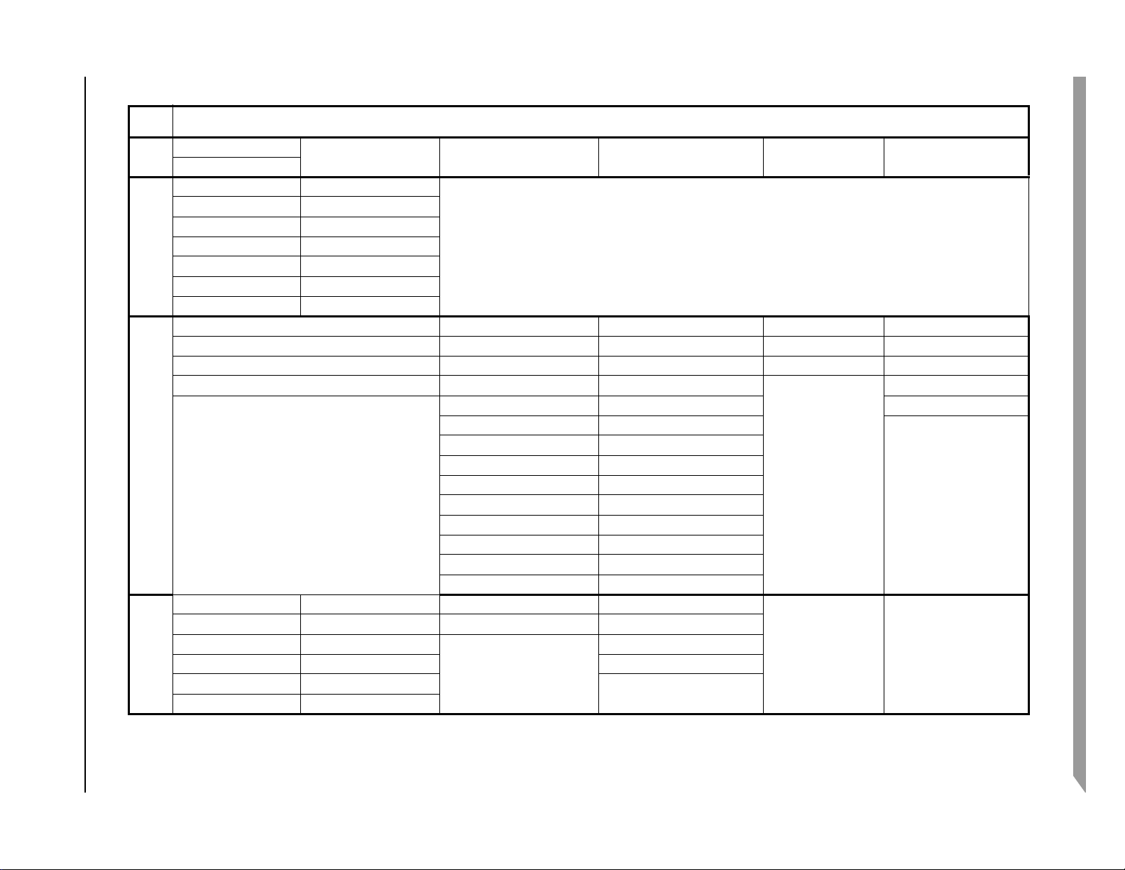
4.2.3 Power Supplies Usage
The following table shows the power supplies usage by group.
i.MX 8QuadMax Automotive and Infotainment Applications Processors, Rev. 1, 12/2020
NXP Semiconductors28
Page 29
NXP Semiconductors 29
Table 15. Power supplies usage
Supply
Groups
Group 0 2.4 - 4.2v
i.MX 8QuadMax Automotive and Infotainment Applications Processors, Rev. 1, 12/2020
Group 1 1.0v 1.8v
Group 2 1.1V 1.8v 1.8v or 3.3v 1.8v or 3.3v switchable 3.3v
Group 3 1.1 - 1.1v 1.0v internal LDO's 1.2v 1.8v or 2.5v or 3.3v
1
MLB is not supported on this product. This MLB power rail must be tied to the voltage specified in Ta bl e 8 if other I/O functions are used as determined by
VDD_SNVS_4P2
VDD_MAIN VDD_ANA1_1P8
VDD_LVDSx_1P0 VDD_ANA2_1P8
VDD_MIPI_CSIx_1P0 VDD_ANA3_1P8
VDD_MIPI_DSIx_1P0 VDD_CP_1P8
VDD_MIPI_DSIx_PLL_1P0 VDD_SCU_1P8
VDD_SCU_x_1P8
VDD_MEMC VDD_ADC_DIG_1P8 VDD_EMMC0_1P8_3P3 VDD_USDHCx_1P8_3P3 VDD_HDMI_RX0_VH_RX_3P3
VDD_DDR_CHx_VDDQ VDD_ADC_1P8 VDD_ESAI0_MCLK_1P8_3P3 VDD_SIM0_1P8_3P3 VDD_HDMI_TX0_DIG_3P3
VDD_DDR_CHx_VDDQ_CKE VDD_ANA0_1P8 VDD_ESAI1_SPDIF_SPI_1P8_3P3 VDD_USB_OTGx_3P3
VDD_DDR_CHx_VDDA_PLL_1P8 VDD_FLEXCAN_1P8_3P3 VDD_USB_SS3_TC_3P3
VDD_HDMI_x_1P8 VDD_LVDS_DIG_1P8_3P3
VDD_LVDSx_1P8 VDD_M4_GPT_UART_1P8_3P3
VDD_MIPI_CSI_DIG_1P8 VDD_MIPI_DSI_DIG_1P8_3P3
VDD_MIPI_x_1P8 VDD_MLB_DIG_1P8_3P3
VDD_MLB_1P8
VDD_PCIE_SATA0_PLL_1P8 VDD_QSPIx_1P8_3P3
VDD_PCIE_x_1P8 VDD_SPI_SAI_1P8_3P3
VDD_PCIEx_PLL_1P8 VDD_USDHC_VSELECT_1P8_3P3
VDD_USB_HSIC0_1P8
VDD_A53 VDD_HDMI_TX0_1P0 VDD_USB_HSIC0_1P2 VDD_ENET_MDIO_1P8_3P3
VDD_A72 VDD_PCIE_SATA0_1P0 VDD_ENET0_1P8_3P3
VDD_GPUx VDD_PCIEx_1P0
VDD_USB_OTGx_1P0
Vol tag e
1
2
VDD_PCIE_DIG_1P8_3P3
VDD_ENET1_1P8_2P5_3P3
IOMUX selection. Alternately, terminate the MLB supply, per the Hardware Developer’s Guide power supplies usage of unused features.
2
MLB is not supported on this product. The MLB power rail must be tied to the voltage specified in Table 8 or may be terminated, per the Hardware Developter’s
Guide power supplies of unused funtions.
Electrical characteristics
Page 30
Electrical characteristics
4.3 PLL electrical characteristics
4.3.1 PLLs of subsystems
i.MX 8QuadMax embeds a large number of PLLs to address clocking requirements of the various
subsystems. These PLLs are controlled through the SCU and not directly by Cortex-A or Cortex-M4F
processors. A software API shall be used by those processors to access the PLL settings. Additional PLLs
are specific to high-performance interfaces. These are described in the following sections.
This table summarizes the PLLs controlled by the SCU.
Table 16. PLLs controlled by SCU
Locking range
Subsystem PLL usage Source clock
Min freq. Max freq.
Cortex-A53
Cortex-A72
CCI Subsystem 24 650 1300 1000 MHz
GPU PLL #0: subsystem 24 1250 2500 • Overdrive: 1600
DRC (DRAM
Controller)
DB (DRAM Block) Subsystem 24 650 1300 750 MHz
DBLog Subsystem 24 650 1300 800 MHz
Display Controller 0 PLL #0: subsystem 24 650 1300 800 MHz
2
3
Subsystem 24 1250 2500 • Overdrive: 2400
Subsystem 24 1250 2500 • Overdrive: 1600
PLL #1: shaders 24 1250 2500 • Overdrive: 2000
Subsystem 24 1250 2500 • LPDDR4: 1600 MHz
PLL #1: display clock #0 24 650 1300 User-configurable MHz
1
• Nominal: 1800
• Nominal: 2120
• Nominal: 1300
• Underdrive: 1600
• Nominal: 1400
• Underdrive: 1600
Lock freq. Unit
MHz
MHz
MHz
4
MHz
5
PLL #2: display clock #1 24 650 1300 User-configurable MHz
Display Controller 1 PLL #0: subsystem 24 650 1300 800 MHz
PLL #1: display clock #0 24 650 1300 User-configurable MHz
PLL #2: display clock #1 24 650 1300 User-configurable MHz
Imaging Subsystem 24 650 1300 1200 MHz
Audio PLL #0: subsystem 24 650 1300 700 MHz
PLL #1: audio PLL #0 24 650 1300 User-configurable MHz
PLL #2: audio PLL #1 24 650 1300 User-configurable MHz
i.MX 8QuadMax Automotive and Infotainment Applications Processors, Rev. 1, 12/2020
NXP Semiconductors30
Page 31

Table 16. PLLs controlled by SCU (continued)
Electrical characteristics
Locking range
Subsystem PLL usage Source clock
Min freq. Max freq.
Connectivity Subsystem 24 650 1300 792 MHz
HSIO (High-speed
I/O)
LSIO (Low-speed
I/O)
Cortex-M4 Subsystem 24 650 1300 792 MHz
VPU PLL #0: subsystem 24 650 1300 1200 MHz
HDMI-TX / eDP Subsystem 24 650 1300 User-configurable MHz
MIPI-DSI Subsystem 24 650 1300 864 MHz
MIPI-CSI Subsystem 24 650 1300 720 MHz
DMA Subsystem 24 650 1300 960 MHz
SCU (System
Controller Unit)
1
Operating frequencies are limited to only those supported by the SCFW.
2
2400 MHz is used to generate the 1200 MHz maximum and 600 MHz slow operating points; 1800 MHz is used to generate the
900 MHz typical operating point. See Ta bl e 8 to get associated voltages.
3
1600 MHz is used for max operating point, 2120 MHz is used to generate 1060 MHz for typical operating point, and 2400 MHz
is used to generate the 600 MHz slow operating point. See Table 8 to get associated voltages.
4
1600 MHz is used to generate 800 MHz for max operating point and 400 MHz for slow operating point. 1300 MHz is used to
generate 650 MHz for typical operating point. See Ta bl e 8 to get associated voltages.
5
2000 MHz is to generate 1000 MHz for max operating point, 1400 MHz is used to generate 700 MHz for typical operating point,
and 1600 MHz is used to generate 400MHz to slow operating point. See Ta b le 8 to get associated voltages.
Subsystem 24 650 1300 800 MHz
Subsystem 24 650 1300 800 MHz
PLL #1: Audio DSP (HiFi 4) 24 650 1300 666 MHz
Subsystem 24 650 1300 1056 MHz
1
Lock freq. Unit
4.3.2 PLLs dedicated to specific interfaces
The following sections cover PLLs used for specific interfaces. Clock output frequency and clock output
range refer to the output of the PLL. Additional clock dividers may be on the output path to divide the
output frequency down to the targeted frequency. See the related sections in the reference manual for
settings of these clock dividers.
i.MX 8QuadMax Automotive and Infotainment Applications Processors, Rev. 1, 12/2020
NXP Semiconductors 31
Page 32

Electrical characteristics
4.3.2.1 Ethernet PLL
This PLL is controlled by the SCU.
Table 17. Ethernet PLL
Parameter Value Unit
Reference clock 24 MHz
Clock output frequency 1 GHz
4.3.2.2 USB 3.0 PLLs
USB 3.0 has two PLLs. One is embedded in Super-Speed PHY. The other one is embedded in the USB 2.0
OTG PHY that is part of the USB 3.0 interface.
The table below describes the PLL embedded in the Super-Speed PHY.
Table 18. USB 3.0 PLL embedded in Super Speed PHY
Parameter Value Unit
Reference clock 24 MHz
Clock output frequency 5 GHz
The table below describes the PLL embedded in the USBOTG PHY.
Table 19. USB 3.0 PLL embedded in USBOTG PHY
Parameter Value Unit
Reference clock 24 MHz
Clock output frequency 480 MHz
4.3.2.3 USB 2.0 OTG and USB-HSIC PLLs
This PLL is embedded in the USB 2.0 OTG PHY (the one which is not part of the USB 3.0 feature). It is
also used to supply the 480 MHz clock to the HSIC interface.
Table 20. USB 2.0 OTG and USB-HSIC PLLs
Parameter Value Unit
Reference clock 24 MHz
Clock output frequency 480 MHz
i.MX 8QuadMax Automotive and Infotainment Applications Processors, Rev. 1, 12/2020
NXP Semiconductors32
Page 33

Electrical characteristics
4.3.2.4 PCIe PLLs
The PCIe interface has seven PLLs:
• One is used to generate the single, common 100 MHz reference clock to each lane
• One Transmit and one Receive PLL per lane (three lanes)
The table below shows the characteristics for the reference clock PLL.
Table 21. PCIe reference clock PLLs
Parameter Value Unit Comments
Reference clock 24 MHz —
Clock output frequency 100 MHz Used to generate internal 100 MHz reference clock to PCIe lanes
The table below shows characteristics of the TX and RX PLLs used in each lane.
Table 22. PCIe Transmit and Receive PLLs
Parameter Value Unit Comments
Reference clock 100 MHz From differential input clock pads or from internal PLL
Clock output range 6 ~ 10 GHz PCIe gen3: 8GHz to get 8GHz baud clock
PCIe gen2: 10GHz to get 5GHz baud clock
PCIe gen1: 10GHz to get 2.5GHz baud clock
1
PCIe 1.0 and 2.0 compliant. PCIe 3.0 capable; contact your NXP representative.
1
4.3.2.5 HDMI-TX / DP PLLs
The HDMI-TX interface uses two PLLs. One is used to generate the reference clock when using the HDMI
PHY itself in HDMI mode. In DP mode, this PLL is bypassed and only the PLL embedded in the PHY is
used.
The table below shows characteristics of the reference clock PLL for HDMI.
Table 23. HDMI reference clock PLL
Parameter Value Unit Comments
Reference clock 24 MHz —
Clock output range 1.25 ~ 2.5 GHz Refer to HDMI / DP section of reference manual
i.MX 8QuadMax Automotive and Infotainment Applications Processors, Rev. 1, 12/2020
NXP Semiconductors 33
Page 34

Electrical characteristics
The table below shows characteristics of the PLL embedded in HDMI/DP PHY.
Table 24. PLL embedded in HDMI/DP PHY
Parameter Value Unit Comments
Reference clock 24MHz / derived from
HDMI-TX PLL
Clock output range ≤5.4 GHz Dependent on targeted display configuration
MHz 24MHz: when in DP mode
derived from HDMI-TX PLL: when in HDMI mode
4.3.2.6 MIPI-DSI PLL
The table below shows characteristics of the PLL embedded in the MIPI-DSI PHY.
Table 25. MIPI-DSIPHY PLL
Parameter Value Unit Comments
Reference clock 24 MHz —
Clock output range 0.75 ~ 1.5 GHz Dependent on targeted display configuration
4.3.2.7 LVDS PLL
The table below shows characteristics of the PLL embedded in LVDS PHY.
Table 2 6 . LV D S PHY P LL
Parameter Value Unit Comments
Reference clock 25 ~ 165 MHz —
Clock output range ≤ 1.25 GHz Dependent on targeted display configuration
4.4 On-chip oscillators
4.4.1 OSC24M
This block integrates trimmable internal loading capacitors and driving circuitry. When combined with a
suitable 24 MHz external quartz element, it can generate a low-jitter clock. The oscillator is powered from
VDD_SCU_XTAL_1P8. The internal loading capacitors are trimmable to provide fine adjustment of the
24 MHz oscillation frequency. It is expected that customers burn appropriate trim values for the selected
crystal and board parasitics.
i.MX 8QuadMax Automotive and Infotainment Applications Processors, Rev. 1, 12/2020
NXP Semiconductors34
Page 35

Electrical characteristics
Figure 2. Normal Crystal Oscillation mode
Table 27. Crystal specifications
Parameter description Min Typ Max Unit
Frequency
Cload
Maximum drive level 200 — — μW
ESR — — 60 Ω
1
The required frequency accuracy is set by the serial interfaces utilized for a specific application and is detailed in the
respective standard documents.
2
Cload is the specification of the quartz element, not for the capacitors coupled to the quartz element.
1
2
—24—MHz
—18—pF
4.4.2 OSC32K
This block implements an internal amplifier, trimmable load capacitors and a bias network that when
combined with a suitable quartz crystal implements a low power oscillator.
Additionally, if the clock monitor determines that the 32KHz oscillation is not present, then the source of
the 32 KHz clock will automatically switch to the internal relaxation oscillator of lesser frequency
accuracy.
i.MX 8QuadMax Automotive and Infotainment Applications Processors, Rev. 1, 12/2020
NXP Semiconductors 35
Page 36

Electrical characteristics
CAUTION
The internal ring oscillator is not meant to be used in customer applications,
due to gross frequency variation over wafer processing, temperature, and
supply voltage. These variations will cause timing issues to many different
circuits that use the internal ring oscillator for reference; and, if this timing
is critical, application issues will occur. To prevent application issues, it is
recommended to only use an external crystal or an accurate external clock.
If this recommendation is not followed, NXP cannot guarantee full
compliance of any circuit using this clock. The OSC32K runs from
VDD_SNVS_LDO_1P8_CAP, which is regulated from VDD_SNVS. The
target battery/voltage range is 2.8 to 4.2 V for VDD_SNVS, with a regulated
output of approximately 1.75 V.
Table 28. OSC32K main characteristics
Parameter Min Typ Max Comments
Fosc — 32.768 kHz — This frequency is nominal and determined mainly by
the crystal selected. 32.0 KHz is also supported.
Current
consumption
Bias resistor — 200 MΩ — This the integrated bias resistor that sets the amplifier
— • xtal oscillator mode: 5 μA
• 32K internal oscillator mode: 10 μA
Target Crystal Properties
— These values are for typical process and room
temperature. Values will be updated after silicon
characterization.
into a high gain state. Any leakage through the ESD
network, external board leakage, or even a scope
probe that is significant relative to this value will
debias the amplifier. The debiasing will result in low
gain, and will impact the circuit's ability to start up and
maintain oscillations.
Cload — 10 pF — Usually crystals can be purchased tuned for different
Cloads. This Cload value is typically 1/2 of the
capacitances realized on the PCB on either side of
the quartz. A higher Cload will decrease oscillation
margin, but increases current oscillating through the
crystal.
ESR — 50 kΩ 100 kΩ Equivalent series resistance of the crystal. Choosing
a crystal with a higher value will decrease the
oscillating margin.
Table 29. External input clock for OSC32K
Min Typ Max Unit Notes
Frequency — 32.768 or 32 — kHz —
VPP RTC_XTALI 700 — VDD_SNVS_LDO_1P8_CAP mV
Rise/fall time — — — ns
i.MX 8QuadMax Automotive and Infotainment Applications Processors, Rev. 1, 12/2020
NXP Semiconductors36
1,2,3
4
Page 37

Electrical characteristics
0
or
1
Predriver
pdat
ovdd
pad
nmos (Rpd)
ovss
Voh min
Vol max
pmos (Rpu)
1
The external clock is fed into the chip from the RTC_XTALI pin; the RTC_XTALO pin should be left floating.
2
The parameter specified here is a peak-to-peak value and VIH/VIL specifications do not apply.
3
The voltage applied on RTC_XTALI must be within the range of VSS to VDD_SNVS_LDO_1P8_CAP.
4
The rise/fall time of the applied clock are not strictly confined.
4.5 I/O DC Parameters
This section includes the DC parameters of the following I/O types:
• XTALI and RTC_XTALI (clock inputs) DC parameters
• General Purpose I/O (GPIO) DC parameters
NOTE
The term ‘OVDD’ in this section refers to the associated supply rail of an
input or output.
Figure 3. Circuit for Parameters Voh and Vol for I/O Cells
4.5.1 XTALI and RTC_XTALI (Clock Inputs) DC Parameters
For RTC_XTALI, VIH/VIL specifications do not apply. The high and low levels of the applied clock on
this pin are not strictly defined, as long as the input’s peak-to-peak amplitude meet the requirements and
the input’s voltage value does not exceed the limits.
4.5.2 General-purpose I/O (GPIO) DC parameters
4.5.2.1 Tri-voltage GPIO DC parameters
The following tables show tri-voltage 1.8V, 2.5 V, and 3.3 V DC parameters, respectively, for GPIO pads.
These parameters are guaranteed per the operating ranges in Table 8, unless otherwise noted.
NXP Semiconductors 37
i.MX 8QuadMax Automotive and Infotainment Applications Processors, Rev. 1, 12/2020
Page 38

Electrical characteristics
Table 30. Tri-voltage 1.8 V GPIO DC parameters
1
Parameter Symbol Test Conditions Min Max Units
High-level output voltage
2,3
V
OH
IOH= -0.1mA
0.8 × OVDD — V
DSE=1
= -2mA
I
OH
DSE=0
Low-level output voltage
2,3
V
OL
IOL= -0.1mA
— 0.125 × OVDD V
DSE=1
IOL= -2mA
DSE=0
High-Level input voltage
Low-Level input voltage
2,4
2,4
Pull-up resistance R
V
IH
V
IL
PU
VIN=0V (Pullup Resistor)
—0.625× OVDD OVDD V
— 0 0.25 × OVDD V
15 50 kΩ
PUN = "L", PDN = "H"
Pull-down resistance R
DOWN
VIN=OVDD( Pulldown Resistor)
15 50 kΩ
PUN = "H", PDN = "L"
Input current (no PU/PD) I
IN
VI = 0, VI = OVDD
-1 1 μA
PUN = "H", PDN = "H"
1
For tri-voltage I/O, the associated IOMUXD compensation control register PSW_OVR and COMP bits must be set correctly.
For 1.8 or 3.3 V operation, the SCFW API must be used to set PSW_OVR = 0b0 and COMP=0b000. For 2.5 V operation,
PSW_OVR = 0b1 and COMP = 0b010.
2
Refer to Section 4.6.1 for undershoot and overshoot specifications.
3
DSE is the setting of the PDRV register. High Drive mode is recommended for 3v3 and 2v5 modes. Low Drive mode is
recommended for 1v8 mode.
4
To maintain a valid level, the transition edge of the input must sustain a constant slew rate (monotonic) from the current DC
level through to the target DC level, V
or VIH. Monotonic input transition time is from 0.1 ns to 1 ns.
IL
Table 31. Tri-voltage 2.5 V GPIO DC parameters
Parameter Symbol Test Conditions Min Max Units
High-level output voltage
Low-level output voltage
High-Level input voltage
Low-Level input voltage
Pull-up resistance RPU VIN=0V (Pullup Resistor)
i.MX 8QuadMax Automotive and Infotainment Applications Processors, Rev. 1, 12/2020
2,3 V
2,3 V
2,4 V
2,4
V
OH
OL
IH
IOH= -2mA
DSE=0
IOL= -2mA
DSE=0
—0.625× OVDD OVDD V
IL
— 0 0.25 × OVDD V
PUN = "L", PDN = "H"
1
0.8 × OVDD — V
—0.125× OVDD V
10 100 kΩ
NXP Semiconductors38
Page 39

Electrical characteristics
Table 31. Tri-voltage 2.5 V GPIO DC parameters1 (continued)
Parameter Symbol Test Conditions Min Max Units
Pull-down resistance R
DOWN
VIN=OVDD( Pulldown
10 100 kΩ
Resistor)
PUN = "H", PDN = "L"
Input current (no PU/PD) I
IN
VI = 0, VI = OVDD
-1 1 μA
PUN = "H", PDN = "H"
1
For tri-voltage I/O, the associated IOMUXD compensation control register PSW_OVR and COMP bits must be set correctly.
For 1.8 or 3.3 V operation, the SCFW API must be used to set PSW_OVR = 0b0 and COMP=0b000. For 2.5 V operation,
PSW_OVR = 0b1 and COMP = 0b010.
2
Refer to Section 4.6.1 for undershoot and overshoot specifications.
3
DSE is the setting of the PDRV register. High Drive mode is recommended for 3v3 and 2v5 modes. Low Drive mode is
recommended for 1v8 mode.
4
To maintain a valid level, the transition edge of the input must sustain a constant slew rate (monotonic) from the current DC
level through to the target DC level, V
or VIH. Monotonic input transition time is from 0.1 ns to 1 ns.
IL
Table 32. Tri-voltage 3.3 V GPIO DC parameters
1
Parameter Symbol Test Conditions Min Max Units
High-level output voltage
2,3
V
OH
IOH= -0.1mA
0.8 × OVDD V
4DSE=1
IOH= -2mA
4DSE=0
Low-level output voltage
2,3 V
OL
IOL= -0.1mA
3
=1
4DSE
— 0.125 × OVDD V
IOL= -2mA
4DSE=0
High-Level input voltage
Low-Level input voltage
2,4
2,4
Pull-up resistance RPU VIN=0V (Pullup Resistor)
V
IH
V
IL
— 0.725 × OVDD OVDD V
— 0 0.25 × OVDD V
10 100 kΩ
PUN = "L", PDN = "H"
Pull-down resistance R
DOWN
VIN=OVDD( Pulldown Resistor)
10 100 kΩ
PUN = "H", PDN = "L"
Input current (no PU/PD) IIN VI = 0, VI = OVDD
-2 2 μA
PUN = "H", PDN = "H"
1
For tri-voltage I/O, the associated IOMUXD compensation control register PSW_OVR and COMP bits must be set correctly.
For 1.8 or 3.3 V operation, the SCFW API must be used to set PSW_OVR = 0b0 and COMP=0b000. For 2.5 V operation,
PSW_OVR = 0b1 and COMP = 0b010.
2
Refer to Section 4.6.1 for undershoot and overshoot specifications.
3
DSE is the setting of the PDRV register. High Drive mode recommended for 3v3 and 2v5 modes. Low Drive mode is
recommended for 1v8 mode.
4
To maintain a valid level, the transition edge of the input must sustain a constant slew rate (monotonic) from the current DC
level through to the target DC level, VIL or VIH. Monotonic input transition time is from 0.1 ns to 1 ns.
i.MX 8QuadMax Automotive and Infotainment Applications Processors, Rev. 1, 12/2020
NXP Semiconductors 39
Page 40

Electrical characteristics
4.5.2.2 Dual-voltage GPIO DC parameters
The following two tables show dual-voltage 1.8 V and 3.3 V DC parameters, respectively, for GPIO
pads. These parameters are guaranteed per the operating ranges in Table 8, unless otherwise noted.
Table 33. Dual-voltage 1.8 V GPIO DC parameters
Parameter Symbol Test Conditions Min Max Units
1,3
1,2
1,3
1,2
OH
Ioh= -0.1mA
V
0.8 × OVDD — V
DSE=1
Ioh= -2mA
DSE=0
V
OL
Iol= -0.1mA
— 0.125 × OVDDV
DSE=1
Iol= -2mA
DSE=0
V
IH
—0.625× OVD
OVDD V
D
V
IL
Vin=0 V (Pullup Resistor)
PU
— 0 0.25 × OVDD V
15 50 kΩ
PUN = "L", PDN = "H"
High-level output voltage
Low-level output voltage
High-Level input voltage
Low-Level input voltage
Pull-up resistance R
Pull-down resistance R
Vin=OVDD( Pulldown Resistor)
down
15 50 kΩ
PUN = "H", PDN = "L"
Input current (no PU/PD) I
VI = 0, VI = OVDD
IN
-1 1 μA
PUN = "H", PDN = "H"
1
Refer to Section 4.6.1 for undershoot and overshoot specifications.
2
DSE is the setting of the PDRV register. High Drive mode is recommended for SD standard (3v3 mode) and MMC standard
(1v8/3v3 modes). Low Drive mode is recommended for SD standard (1v8 mode).
3
To maintain a valid level, the transition edge of the input must sustain a constant slew rate (monotonic) from the current DC
level through to the target DC level, Vil or Vih. Monotonic input transition time is from 0.1 ns to 1 ns.
Table 34. Dual-voltage 3.3 V GPIO DC parameters
Parameter Symbol Test Conditions Min Max Units
1,2
1,3
1,2
V
OH
Ioh= -0.1mA
0.8 × OVDD — V
DSE=1
Ioh= -2mA
DSE=0
V
OL
Iol= -0.1mA
—0.125× OVDD V
DSE=1
Iol= -2mA
DSE=0
V
IH
—0.725× OVDD OVDD V
High-level output voltage
Low-level output voltage
High-Level input voltage
i.MX 8QuadMax Automotive and Infotainment Applications Processors, Rev. 1, 12/2020
NXP Semiconductors40
Page 41

Table 34. Dual-voltage 3.3 V GPIO DC parameters (continued)
Parameter Symbol Test Conditions Min Max Units
Low-Level input voltage
Pull-upresistance R
1,3
Electrical characteristics
V
IL
PU
Vin=0V (Pullup Resistor)
— 0 0.25 × OVDD V
10 100 kΩ
PUN = "L", PDN = "H"
Pull-down resistance R
down
Vin=OVDD( Pulldown Resistor)
10 100 kΩ
PUN = "H", PDN = "L"
Input current (no PU/PD) I
IN
VI = 0, VI = OVDD
-2 2 μA
PUN = "H", PDN = "H"
1
Refer to Section 4.6.1 for undershoot and overshoot specifications.
2
DSE is the setting of the PDRV register. High Drive mode is recommended for SD standard (3v3 mode) and MMC standard
(1v8/3v3 modes). Low Drive mode is recommended for SD standard (1v8 mode).
3
To maintain a valid level, the transition edge of the input must sustain a constant slew rate (monotonic) from the current DC
level through to the target DC level, VIL or VIH. Monotonic input transition time is from 0.1 ns to 1 ns.
4.5.2.3 Single-voltage GPIO DC parameters
Table 35 and Table 36 show single-voltage 1.8 V and 3.3 V DC parameters, respectively, for GPIO pads.
These parameters are guaranteed per the operating ranges in Table 8 unless otherwise noted.
Table 35. Single-voltage 1.8 V GPIO DC parameters
Parameter Symbol Test Conditions Min Max Units
High-level output voltage
1,2
V
OH
IOH= -0.1mA
OVDD × 0.8 — V
DSE = 000 or 001
IOH= -2mA
DSE = 010 or 011
= -4mA
I
OH
DSE = 100 to 110
Low-level output voltage
1,2
V
OL
IOL= 0.1mA
—OVDD× 0.2 V
DSE = 000 or 001
IOL= 2mA
DSE = 010 or 011
= 4mA
I
OL
DSE = 100 to 110
High-Level input voltage
Low-Level input voltage
Pull-up resistance R
2,3
2,3
V
IH
V
IL
PU
Vin=0V (Pullup Resistor)
—0.65× OVDD OVDD V
— 0 0.35 × OVDD V
20 90 kΩ
PUN = "L", PDN = "H"
Pull-down resistance R
down
Vin=OVDD( Pulldown Resistor)
20 90 kΩ
PUN = "H", PDN = "L"
i.MX 8QuadMax Automotive and Infotainment Applications Processors, Rev. 1, 12/2020
NXP Semiconductors 41
Page 42

Electrical characteristics
Parameter Symbol Test Conditions Min Max Units
Table 35. Single-voltage 1.8 V GPIO DC parameters (continued)
Input current (no PU/PD) I
IN
VI = 0, VI = OVDD
-5 5 μA
PUN = "H", PDN = "H"
Keeper Circuit Resistance R_Keeper V
=.3xOVDD, VI = .7x OVDD
I
20 90 kΩ
PUN = "L", PDN = "L"
1
As programmed in the associated IOMUX (DSE field) register.
2
Refer to Section 4.6.1 for undershoot and overshoot specifications.
3
To maintain a valid level, the transition edge of the input must sustain a constant slew rate (monotonic) from the current DC
level through to the target DC level, V
or VIH. Monotonic input transition time is from 0.1 ns to 1 ns.
IL
Table 36. Single-voltage 3.3 V GPIO DC parameters
Parameter Symbol Test Conditions Min Max Units
High-level output voltage
Low-level output voltage
High-Level input voltage
Low-Level input voltage
1,2
1,2
2,3
2,3
Pull-upresistance R
V
OH
I
OH
= -0.1mA
0.8 × OVDD — V
DSE = 00 or 01
IOH= -2mA
DSE = 10 or 11
V
OL
IOL=0.1mA
—0.2× OVDD V
DSE = 00 or 01
= 2mA
I
OL
DSE = 10 or 11
V
IH
V
IL
PU
Vin=0 V (Pullup Resistor)
—0.75× OVDD OVDD V
—00.25× OVDD V
20 90 kΩ
PUN = "L", PDN = "H"
Pull-down resistance R
down
Vin=OVDD( Pulldown Resistor)
20 90 kΩ
PUN = "H", PDN = "L"
Input current (no PU/PD) I
IN
VI = 0, VI = OVDD
-5 5 μA
PUN = "H", PDN = "H"
Keeper Circuit Resistance R_Keeper VI =.3xOVDD, VI = .7x OVDD
20 90 kΩ
PUN = "L", PDN = "L"
1
As programmed in the associated IOMUX (DSE field) register.
2
Refer to Section 4.6.1 for undershoot and overshoot specifications.
3
To maintain a valid level, the transition edge of the input must sustain a constant slew rate (monotonic) from the current DC
level through to the target DC level, V
or VIH. Monotonic input transition time is from 0.1 ns to 1 ns.
IL
4.5.3 HDMI control signals parameters
The following table shows HDMI control signals DC parameters. These parameters are guaranteed per the
operating ranges in Table 8, unless otherwise noted.
i.MX 8QuadMax Automotive and Infotainment Applications Processors, Rev. 1, 12/2020
NXP Semiconductors42
Page 43

Electrical characteristics
Test Point
From Output
CL
CL includes package, probe and fixture capacitance
Under Test
Table 37. HDMI DDC and HPD DC parameters
Parameter Symbol Test Conditions Min Max Units
High-level input voltage V
Low-level input voltage V
IH
IL
—25.3V
—00.8V
4.5.4 DDR I/O DC parameters
4.5.4.1 LPDDR4 mode I/O DC parameters
These parameters are guaranteed per the operating ranges in Table 8 unless otherwise noted.
Table 38. LPDDR4 DC parameters
Parameter Symbol Test Conditions Min Max Units
High-level output voltage
Low-level output voltage
Input current (no ODT) I
DC High-Level input voltage V
DC Low-Level input voltage V
1
Refer to Section 4.6.1 for undershoot and overshoot specifications.
1
1
V
OH
V
OL
IN
IH_DC
IL_DC
Out Drive = All setting
(40,48,60,80,120,240)
unterminated outputs loaded
with 1pF capacitor load
Out Drive = All setting
(40,48,60,80,120,240)
unterminated outputs loaded
with 1pF capacitor load
VI = VSSQ, VI = VDDQ -2 2 μA
—VREF+0.1VDDQV
— VSSQ VREF – 0.1 V
0.9 × V
DDQ
—0.1× V
—V
DDQ
V
4.6 I/O AC Parameters
The GPIO and DDR I/O load circuit and output transition time waveforms are shown in Figure 4 and
Figure 5.
NXP Semiconductors 43
i.MX 8QuadMax Automotive and Infotainment Applications Processors, Rev. 1, 12/2020
Figure 4. Load Circuit for Output
Page 44

Electrical characteristics
0V
OVDD
20%
80%
80%
20%
tr
tf
Output (at pad)
VPEAK
A
B
Figure 5. Output Transition Time Waveform
4.6.1 I/O Overshoot and Undershoot Parameters
For all inputs/outputs, maximum peak amplitude allowed for overshoot and undershoot is specified in
Table 39. OVDD is the I/O Supply.
NOTE
If a signal edge produces more than one overshoot/undershoot event, the
sum of all areas following the transition must be less than the area specified.
Table 39. Overshoot and Undershoot Parameters
Parameter Symbol Min Max Units
Amplitude above OVDD or below GND V
Area above OVDD or below GND (A + B) V
Peak
Area
—0.35V
—0.8V-ns
Overshoot/undershoot must be controlled through printed circuit board layout, transmission line
impedance matching, signal line termination, and other methods. Noncompliance to this specification may
affect device reliability or cause permanent damage to the device.
Figure 6. Undershoot Waveform Example
i.MX 8QuadMax Automotive and Infotainment Applications Processors, Rev. 1, 12/2020
NXP Semiconductors44
Page 45

4.6.2 General Purpose I/O (GPIO) AC Parameters
Electrical characteristics
Table 40. General Purpose I/O AC Parameters
1
Symbol Parameter Test Condition Min Typ Max Unit
2
—— 208 MHz
f
max
1.8 V application
Maximum frequency Load = 21 pF (PDRV = H, high
drive, Type A, 33 Ω
Load = 15 pF (PDRV = L, low
drive, Type B, 50 Ω
tr Rise time Measured between V
V
OH
OL
and
tf Fall time Measured between VOH and
V
OL
3
f
max
Driver 3.3 V application
Maximum frequency Load = 30 pF — — 52 MHz
tr Rise time Measured between
and V
V
OL
OH
tf Fall time Measured between
and V
V
OH
1
All output I/O specifications are guaranteed for Accurate mode of the compensation cell operation. This is applicable for both
OL
0.4 — 1.32 ns
0.4 — 1.32 ns
—— 3 ns
—— 3 ns
DC and AC specifications.
2
All timing specifications in 1.8 V application are valid for High Drive mode (PDRV = H). In Low Drive mode (PDRV = L), the
driver is functional.
3
All timing specifications in 3.3 V application are valid for Type B driver only. In Type A, the driver is functional.
Table 41. Dynamic input characteristics
Symbol Parameter Condition
Dynamic Input Characteristics for 3.3 V Application
f
op
Input frequency of operation — — 52 MHz
INPSL Slope of input signal at I/O Measured between 10% to 90% of the I/O swing — 3.5 ns
IOMAX High level input voltage — — 3.3 V + 0.3 V V
IOMIN Low level input voltage — -0.3 V —
Dynamic Input Characteristics for 1.8 V Application
f
op
Input frequency of operation — — 208 MHz
INPSL Slope of input signal at I/O Measured between 10% to 90% of the I/O swing — 1.5 ns
IOMAX High level input voltage — — 1.8 V + 0.3 V V
IOMIN Low level input voltage — -0.3 V —
i.MX 8QuadMax Automotive and Infotainment Applications Processors, Rev. 1, 12/2020
NXP Semiconductors 45
1,2
Min Max Unit
Page 46

Electrical characteristics
1
For all supply ranges of operation.
2
The dynamic input characteristic specifications are applicable for the digital bidirectional cells.
4.7 Output Buffer Impedance Parameters
This section defines the I/O impedance parameters for the following I/O types:
• General Purpose I/O (GPIO) output buffer impedance
• Double Data Rate I/O (DDR) output buffer impedance for LPDDR4
NOTE
GPIO and DDR I/O output driver impedance is measured with “long”
transmission line of impedance Ztl attached to I/O pad and incident wave
launched into transmission line. Rpu/Rpd and Ztl form a voltage divider that
defines specific voltage of incident wave relative to OVDD. Output driver
impedance is calculated from this voltage divider (see Figure 7).
i.MX 8QuadMax Automotive and Infotainment Applications Processors, Rev. 1, 12/2020
NXP Semiconductors46
Page 47

Electrical characteristics
ipp_do
Cload = 1p
Ztl Ω, L = 20 inches
predriver
PMOS (Rpu)
NMOS (Rpd)
pad
OVDD
OVSS
t,(ns)
U,(V)
OVDD
t,(ns)
0
VDD
Vin
(do)
Vout (pad)
U,(V)
Vref
Rpu =
Vovdd–Vref1
Vref1
× Ztl
Rpd =
× Ztl
Vref2
Vovdd–Vref2
Vref1
Vref2
0
Figure 7. Impedance Matching Load for Measurement
4.7.1 GPIO output buffer impedance
4.7.1.1 Tri-voltage GPIO output buffer impedance
Table 42. Tri-voltage 1.8 V GPIO output impedance DC parameters
Parameter Symbol Test conditions Typical Units
Output impedance Z
Output impedance Z
O
O
1
DSE=0 33 Ω
1
DSE=1 50 Ω
NXP Semiconductors 47
i.MX 8QuadMax Automotive and Infotainment Applications Processors, Rev. 1, 12/2020
Page 48

Electrical characteristics
1
As programmed in the associated IOMUX (PDRV field) register.
Table 43. Tri-voltage 2.5 V GPIO output impedance DC parameters
Parameter Symbol Test conditions Typical Units
Output impedance Z
Output impedance Z
1
As programmed in the associated IOMUX (PDRV field) register.
O
O
1
DSE=0
1
DSE=1 33 Ω
25 Ω
Table 44. Tri-voltage 3.3 V GPIO output impedance DC parameters
Parameter Symbol Test conditions Typical Units
Output impedance Z
Output impedance Z
1
As programmed in the associated IOMUX (PDRV field) register.
O
O
1
DSE=0
1
DSE=1 37 Ω
25 Ω
4.7.1.2 Dual-voltage GPIO output buffer impedance
Table 45. Dual-voltage 1.8 V GPIO output impedance DC parameters
Parameter Symbol Test conditions Typical Units
Output impedance Z
Output impedance Z
1
‘As programmed in the associated IOMUX (PDRV field) register.
O
O
1
DSE=0
1
DSE=1 50 Ω
Table 46. Dual-voltage 3.3 V GPIO output impedance DC parameters
Parameter Symbol Test conditions Typical Units
Output impedance Z
Output impedance Z
1
As programmed in the associated IOMUX (PDRV field) register.
O
O
1
DSE=0
1
DSE=1 37 Ω
33 Ω
25 Ω
i.MX 8QuadMax Automotive and Infotainment Applications Processors, Rev. 1, 12/2020
NXP Semiconductors48
Page 49

Electrical characteristics
4.7.1.3 Single-voltage 1.8 V GPIO output buffer drive strength
The following table shows the GPIO output buffer drive strength (OVDD 1.8 V).
Table 47. Single-voltage GPIO 1.8 V output impedance DC parameters
Parameter Symbol Test conditions Typical Units
1
Output impedance Z
1
As programmed in the associated IOMUX (DSE field) register.
O
DSE=000
1
DSE=001 100
1
DSE=010 55
1
DSE=011 40
1
DSE=100 30
1
DSE=101 24
1
DSE=110 20
1
DSE=111 18
200 Ω
4.7.1.4 Single-voltage 3.3 V GPIO output buffer drive strength
The following table shows the GPIO output buffer drive strength (OVDD 3.3 V).
Table 48. Single-voltage GPIO 3.3 V output impedance DC parameters
Parameter Symbol Test conditions Typical Units
1
Output impedance Z
1
As programmed in the associated IOMUX (DSE field) register.
O
DSE=00
1
DSE=01 200
1
DSE=10 100
1
DSE=11 50
400 Ω
i.MX 8QuadMax Automotive and Infotainment Applications Processors, Rev. 1, 12/2020
NXP Semiconductors 49
Page 50

Electrical characteristics
4.7.2 DDR I/O output buffer impedance
The following tables show LPDDR4 I/O output buffer impedance of the device.
The ZQ Calibration cell uses a single register (ZQnPR0) to determine the target output buffer impedances
of the pull-up driver and the pull-down driver, as well as the target on-die termination impedance. The
resulting calibration setting is then applied to all DDR pads within the PHY complex.
Table 49 shows the recommended ZQnPR0 field settings for the LPDDR4 I/Os to achieve the desired
output buffer impedances.
Table 49. LPDDR4 I/O output buffer impedance
Typical
Parameter
ZPROG_ASYM_PU_DRV
ZQnPR0
Impedance
ZQnPR0
ZPROG_ASYM_PD_DRV
Impedance
Recommended combinations
for DQ /CA pins
580 Ω 3 120 Ω
760 Ω 580 Ω
948 Ω 760 Ω
11 4 0 Ω 948 Ω
Table 50. LPDDR4 I/O on-die termination impedance
Parameter
Recommended combinations
for DQ/CA pins
Typical
Impedance
120.0 Ω 3
80.0 Ω 5
60.0 Ω 7
48.0 Ω 9
40.0 Ω 11
ZQnPR0. ZPROG_HOST_ODT
4.8 System Modules Timing
This section contains the timing and electrical parameters for the modules in each processor.
i.MX 8QuadMax Automotive and Infotainment Applications Processors, Rev. 1, 12/2020
NXP Semiconductors50
Page 51

Electrical characteristics
POR_B
CC1
(Input)
4.8.1 Reset Timing Parameters
The following figure shows the reset timing and Table 51 lists the timing parameters.
Figure 8. Reset timing diagram
Table 51. Reset timing parameters
ID Parameter Min Max Unit
CC1 Duration of SRC_POR_B to be qualified as valid 1 — XTALOSC_RTC_ XTALI cycle
4.8.2 WDOG reset timing parameters
The following figure shows the WDOG reset timing and Table 52 lists the timing parameters.
Figure 9. SCU_WDOG_OUT timing diagram
Table 52. WDOG1_B timing parameters
ID Parameter Min Max Unit
CC3 Duration of SCU_WDOG_OUT assertion 1 — XTALOSC_RTC_ XTALI cycle
NOTE
XTALOSC_RTC_XTALI is approximately 32 kHz.
XTALOSC_RTC_XTALI cycle is one period or approximately 30 μs.
i.MX 8QuadMax Automotive and Infotainment Applications Processors, Rev. 1, 12/2020
NXP Semiconductors 51
Page 52

Electrical characteristics
4.8.3 DDR SDRAM–specific parameters (LPDDR4)
The i.MX 8 Family of processors have been designed and tested to work with JEDEC JESD209-4A–
compliant LPDDR4 memory . Timing diagrams and tolerances required to work with these memories are
specified in the respective documents and are not reprinted here.
Meeting the necessary timing requirements for a DDR memory system is highly dependent on the
components chosen and the design layout of the system as a whole. NXP cannot cover in this document
all the requirements needed to achieve a design that meets full system performance over temperature,
voltage, and part variation; PCB trace routing, PCB dielectric material, number of routing layers used,
placement of bulk/decoupling capacitors on critical power rails, VIA placement, GND and Supply planes
layout, and DDR controller/PHY register settings all are factors affecting the performance of the memory
system. Consult the hardware user guide for this device and NXP validated design layouts for information
on how to properly design a PCB for best DDR performance. NXP strongly recommends duplicating an
NXP validated design as much as possible in the design of critical power rails, placement of
bulk/decoupling capacitors and DDR trace routing between the processor and the selected DDR memory.
All supporting material is readily available on the device web page on
https://www.nxp.com/products/processors-and-microcontrollers/applications-processors/i.mx-applicatio
ns-processors/i.mx-8-processors:IMX8-SERIES .
Processors that demonstrate full DDR performance on NXP validated designs, but do not function on
customer designs, are not considered marginal parts. A report detailing how the returned part behaved on
an NXP validated system will be provided to the customer as closure to a customer’s reported DDR issue.
Customers bear the responsibility of properly designing the Printed Circuit Board, correctly simulating and
modeling the designed DDR system, and validating the system under all expected operating conditions
(temperatures, voltages) prior to releasing their product to market.
Table 53. i.MX 8 Family DRAM controller supported SDRAM configurations
Parameter LPDDR4
Number of Controllers 2
Number of Channels 2 per controller
Number of Chip Selects 2 per channel
Bus Width 16 bit per channel
Number of Address Rows 16 (R0-R15)
Maximum Clock Frequency 1600 MHz
1
Only 16-bit external memory configurations are supported.
1
4.8.3.1 Clock/data/command/address pin allocations
These processors uses generic names for clock, data and command address bus (DCF—DRAM controller
functions); the following table provides mapping of clock, data and command address signals for LPDDR4
modes.
i.MX 8QuadMax Automotive and Infotainment Applications Processors, Rev. 1, 12/2020
NXP Semiconductors52
Page 53

Electrical characteristics
Table 54. Clock, data, and command address signals for LPDDR4 modes
Signal name LPDDR4
DDR_CH[1:0].CK0_P CK_t_A
DDR_CH[1:0].CK0_N CK_c_A
DDR_CH[1:0].CK1_P CK_t_B
DDR_CH[1:0].CK1_N CK_c_B
DDR_CH[1:0].DQ_[15:0] DQ[15:0]_A
DDR_CH[1:0].DQ_[31:16] DQ[15:0]_B
DDR_CH[1:0].DQS_N_[3:0] DQS_N_[3:0]
DDR_CH[1:0].DQS_P_[3:0] DQS_P_[3:0]
DDR_CH[1:0].DM_[3:0] DM_[3:0]
DDR_CH[1:0].DCF00 CA2_A
DDR_CH[1:0].DCF01 CA4_A
DDR_CH[1:0].DCF02
DDR_CH[1:0].DCF03 CA5_A
DDR_CH[1:0].DCF04
DDR_CH[1:0].DCF05
DDR_CH[1:0].DCF06
DDR_CH[1:0].DCF07
DDR_CH[1:0].DCF08 CA3_A
DDR_CH[1:0].DCF09 ODT_CA_A
DDR_CH[1:0].DCF10 CS0_A
DDR_CH[1:0].DCF11 CA0_A
DDR_CH[1:0].DCF12 CS1_A
DDR_CH[1:0].DCF13
DDR_CH[1:0].DCF14 CKE0_A
DDR_CH[1:0].DCF15 CKE1_A
DDR_CH[1:0].DCF16 CA1_A
DDR_CH[1:0].DCF17 CA4_B
DDR_CH[1:0].DCF18 RESET_N
DDR_CH[1:0].DCF19 CA5_B
DDR_CH[1:0].DCF20
DDR_CH[1:0].DCF21
DDR_CH[1:0].DCF22
i.MX 8QuadMax Automotive and Infotainment Applications Processors, Rev. 1, 12/2020
NXP Semiconductors 53
Page 54

Electrical characteristics
Table 54. Clock, data, and command address signals for LPDDR4 modes (continued)
Signal name LPDDR4
DDR_CH[1:0].DCF23
DDR_CH[1:0].DCF24
DDR_CH[1:0].DCF25 ODT_CA_B
DDR_CH[1:0].DCF26 CA3_B
DDR_CH[1:0].DCF27 CA0_B
DDR_CH[1:0].DCF28 CS0_B
DDR_CH[1:0].DCF29 CS1_B
DDR_CH[1:0].DCF30 CKE0_B
DDR_CH[1:0].DCF31 CKE1_B
DDR_CH[1:0].DCF32 CA1_B
DDR_CH[1:0].DCF33 CA2_B
4.9 General-Purpose Media Interface (GPMI) Timing
The GPMI controller is a flexible interface NAND Flash controller with 8-bit data width, up to 400 MB/s
I/O speed, and individual chip select. It supports Asynchronous Timing mode, Source Synchronous
Timing mode, and Toggle Timing mode, as described in the following subsections.
i.MX 8QuadMax Automotive and Infotainment Applications Processors, Rev. 1, 12/2020
NXP Semiconductors54
Page 55

Electrical characteristics
Command
.!.$?#,%
.!.$?!,%
.!.$?$!4!XX
NF8 NF9
NF7
NF6
NF5
NF2
NF1
NF3
NF4
Address
NF10
NF11
NF9NF8
NF7
NF6
NF5
NF1
NF3
.!.$?#,%
.!.$?#%?"
.!.$?7%?"
.!.$?!,%
NAND_DATAxx
Data to NF
NF10
NF11
NF7
NF6
NF5
NF1
NF3
.!.$?#,%
.!.$?#%?"
.!.$?7%?"
.!.$?!,%
NF9
NF8
4.9.1 GPMI Asynchronous mode AC timing (ONFI 1.0 compatible)
Asynchronous mode AC timings are provided as multiplications of the clock cycle and fixed delay. The
Maximum I/O speed of GPMI in Asynchronous mode is about 50 MB/s. Figure 10 through Figure 13
depict the relative timing between GPMI signals at the module level for different operations under
Asynchronous mode. Table 55 describes the timing parameters (NF1–NF17) that are shown in the figures.
Figure 10. Command Latch Cycle Timing Diagram
Figure 11. Address Latch Cycle Timing Diagram
Figure 12. Write Data Latch Cycle Timing Diagram
i.MX 8QuadMax Automotive and Infotainment Applications Processors, Rev. 1, 12/2020
NXP Semiconductors 55
Page 56

Electrical characteristics
Data from NF
NF14
NF15
NF17
NF16
NF12
NF13
.!.$?#,%
.!.$?#%?"
.!.$?2%?"
.!.$?$!4!XX
Data from NF
NF14
NF15
NF17
NF16
NF12
NF13
.!.$?#,%
.!.$?#%?"
.!.$?2%?"
.!.$?2%!$9?"
NAND_DATAxx
Figure 13. Read Data Latch Cycle Timing Diagram (Non-EDO Mode)
Figure 14. Read Data Latch Cycle Timing Diagram (EDO Mode)
Table 55. Asynchronous Mode Timing Parameters
Timing
ID Parameter Symbol
NF1 NAND_CLE setup time tCLS (AS + DS) × T - 0.12 [see
NF2 NAND_CLE hold time tCLH DH × T - 0.72 [see 2]ns
NF3 NAND_CEx_B setup time tCS (AS + DS + 1) × T [see
NF4 NAND_CEx_B hold time tCH (DH+1) × T - 1 [see
NF5 NAND_WE_B pulse width tWP DS × T [see 2]ns
NF6 NAND_ALE setup time tALS (AS + DS) × T - 0.49 [see
NF7 NAND_ALE hold time tALH (DH × T - 0.42 [see
NF8 Data setup time tDS DS × T - 0.26 [see 2]ns
NF9 Data hold time tDH DH × T - 1.37 [see 2]ns
NF10 Write cycle time tWC (DS + DH) × T [see
NF11 NAND_WE_B hold time tWH DH × T [see 2]ns
NF12 Ready to NAND_RE_B low tRR
4
(AS + 2) × T [see
NF13 NAND_RE_B pulse width tRP DS × T [see
NF14 READ cycle time tRC (DS + DH) × T [see 2]ns
NF15 NAND_RE_B high hold time tREH DH × T [see 2]ns
i.MX 8QuadMax Automotive and Infotainment Applications Processors, Rev. 1, 12/2020
T = GPMI Clock Cycle
Min Max
3,2
]—ns
1
Unit
2,3
]ns
3,2
]ns
2
]ns
3,2
]ns
2
]ns
2
]ns
2
]ns
NXP Semiconductors56
Page 57

Electrical characteristics
Table 55. Asynchronous Mode Timing Parameters1 (continued)
Timing
ID Parameter Symbol
NF16 Data setup on read tDSR — (DS × T -0.67)/18.38 [see
NF17 Data hold on read tDHR 0.82/11.83 [see
1
The GPMI asynchronous mode output timing can be controlled by the module’s internal registers
HW_GPMI_TIMING0_ADDRESS_SETUP, HW_GPMI_TIMING0_DATA_SETUP, and HW_GPMI_TIMING0_DATA_HOLD.
This AC timing depends on these registers settings. In the table, AS/DS/DH represents each of these settings.
2
AS minimum value can be 0, while DS/DH minimum value is 1.
3
T = GPMI clock period -0.075ns (half of maximum p-p jitter).
4
NF12 is met automatically by the design.
5
Non-EDO mode.
6
EDO mode, GPMI clock ≈ 100 MHz
(AS=DS=DH=1, GPMI_CTL1 [RDN_DELAY] = 8, GPMI_CTL1 [HALF_PERIOD] = 0).
T = GPMI Clock Cycle
Min Max
5,6
]—ns
Unit
5,6
]ns
In EDO mode (Figure 14), NF16/NF17 are different from the definition in non-EDO mode (Figure 13).
They are called tREA/tRHOH (NAND_RE_B access time/NAND_RE_B HIGH to output hold). The
typical value for them are 16 ns (max for tREA)/15 ns (min for tRHOH) at 50 MB/s EDO mode. In EDO
mode, GPMI will sample NAND_DATAxx at rising edge of delayed NAND_RE_B provided by an
internal DPLL. The delay value can be controlled by GPMI_CTRL1.RDN_DELAY (see the GPMI chapter
of the device reference manual. The typical value of this control register is 0x8 at 50 MT/s EDO mode.
However, if the board delay is large enough and cannot be ignored, the delay value should be made larger
to compensate the board delay.
i.MX 8QuadMax Automotive and Infotainment Applications Processors, Rev. 1, 12/2020
NXP Semiconductors 57
Page 58

Electrical characteristics
NF18
NF25
NF26
NF25
NF26
NF20
NF21
NF20
NF23
NF24
NF19
NF22
NF21
CMD
ADD
.!.$?#%?"
NAND_CLE
NAND_ALE
NAND_WE/RE_B
NAND_CLK
NAND_DQS
NAND_DQS
Output enable
NAND_DATA[7:0]
NAND_DATA[7:0]
Output enable
4.9.2 GPMI Source Synchronous mode AC timing (ONFI 2.x compatible)
The following figure shows the write and read timing of Source Synchronous mode.
Figure 15. Source Synchronous Mode Command and Address Timing Diagram
i.MX 8QuadMax Automotive and Infotainment Applications Processors, Rev. 1, 12/2020
NXP Semiconductors58
Page 59

Electrical characteristics
NF23
NF18
NF25
NF26
NF27
NF25
NF26
NF28
NF28
NF29
NF29
NF23
NF24
NF24
NF19
NF27
NF22
.!.$?#%?"
.!.$?#,%
.!.$?!,%
NAND_WE/RE_B
.!.$?#,+
.!.$?$13
.!.$?$13
Output enable
.!.$?$1;=
.!.$?$1;=
Output enable
NF23
NF18
NF25
NF26
NF25
NF26
NF23
NF24
NF24
NF19
NF22
NF25
NF26
.!.$?#%?"
.!.$?#,%
NAND_ALE
.!.$?7%2%
.!.$?#,+
.!.$?$13
.!.$?$13
/UTPUTENABLE
.!.$?$!4!;=
.!.$?$!4!;=
/UTPUTENABLE
NF25
Figure 16. Source Synchronous Mode Data Write Timing Diagram
Figure 17. Source Synchronous Mode Data Read Timing Diagram
i.MX 8QuadMax Automotive and Infotainment Applications Processors, Rev. 1, 12/2020
NXP Semiconductors 59
Page 60

Electrical characteristics
D0 D1 D2 D3
.!.$?$13
.!.$?$!4!;=
NF30
NF31
NF30
NF31
Figure 18. NAND_DQS/NAND_DQ Read Valid Window
Table 56. Source Synchronous Mode Timing Parameters
ID Parameter Symbol
NF18 NAND_CEx_B access time tCE CE_DELAY × T - 0.79 [see
NF19 NAND_CEx_B hold time tCH 0.5 × tCK - 0.63 [see
NF20 Command/address NAND_DATAxx setup time tCAS 0.5 × tCK - 0.05 ns
NF21 Command/address NAND_DATAxx hold time tCAH 0.5 × tCK - 1.23 ns
NF22 clock period tCK — ns
NF23 preamble delay tPRE PRE_DELAY × T - 0.29 [see
NF24 postamble delay tPOST POST_DELAY × T - 0.78 [see 2]ns
NF25 NAND_CLE and NAND_ALE setup time tCALS 0.5 × tCK - 0.86 ns
NF26 NAND_CLE and NAND_ALE hold time tCALH 0.5 × tCK - 0.37 ns
NF27 NAND_CLK to first NAND_DQS latching transition tDQSS T - 0.41 [see
NF28 Data write setup tDS 0.25 × tCK - 0.35 ns
NF29 Data write hold tDH 0.25 × tCK - 0.85 ns
NF30 NAND_DQS/NAND_DQ read setup skew tDQSQ — 2.06 —
NF31 NAND_DQS/NAND_DQ read hold skew tQHS — 1.95 —
1
The GPMI source synchronous mode output timing can be controlled by the module’s internal registers
GPMI_TIMING2_CE_DELAY, GPMI_TIMING_PREAMBLE_DELAY, GPMI_TIMING2_POST_DELAY. This AC timing
depends on these registers settings. In the table, CE_DELAY/PRE_DELAY/POST_DELAY represents each of these settings.
2
T = tCK (GPMI clock period) -0.075ns (half of maximum p-p jitter).
T = GPMI Clock Cycle
Min Max
1
Timing
Unit
2
]
2
]ns
2
]ns
2
]ns
ns
Figure 18 shows the timing diagram of NAND_DQS/NAND_DATAxx read valid window. For Source
Synchronous mode, the typical value of tDQSQ is 0.85 ns (max) and 1 ns (max) for tQHS at 200 MB/s.
GPMI will sample NAND_DATA[7:0] at both rising and falling edge of a delayed NAND_DQS signal,
which can be provided by an internal DPLL. The delay value can be controlled by GPMI register
GPMI_READ_DDR_DLL_CTRL.SLV_DLY_TARGET (see the GPMI chapter of the device reference
manual. Generally, the typical delay value of this register is equal to 0x7 which means 1/4 clock cycle
delay expected. However, if the board delay is large enough and cannot be ignored, the delay value should
be made larger to compensate the board delay.
i.MX 8QuadMax Automotive and Infotainment Applications Processors, Rev. 1, 12/2020
NXP Semiconductors60
Page 61

Electrical characteristics
4.9.3 ONFI NV-DDR2 mode (ONFI 3.2 compatible)
4.9.3.1 Command and address timing
ONFI 3.2 mode command and address timing is the same as ONFI 1.0 compatible Async mode AC timing.
See Section 4.9.1, “GPMI Asynchronous mode AC timing (ONFI 1.0 compatible)",” for details.
4.9.3.2 Read and write timing
ONFI 3.2 mode read and write timing is the same as Toggle mode AC timing. See Section 4.9.4, “Toggle
mode AC Timing",” for details.
4.9.4 Toggle mode AC Timing
4.9.4.1 Command and address timing
NOTE
Toggle mode command and address timing is the same as ONFI 1.0
compatible Asynchronous mode AC timing. See Section 4.9.1, “GPMI
Asynchronous mode AC timing (ONFI 1.0 compatible)",” for details.
4.9.4.2 Read and write timing
Figure 19. Toggle mode data write timing
i.MX 8QuadMax Automotive and Infotainment Applications Processors, Rev. 1, 12/2020
NXP Semiconductors 61
Page 62

Electrical characteristics
DEV?CLK
.!.$?#%X?"
.!.$?#,%
.!.$?!,%
.!.$?7%?"
.!.$?2%?"
.!.$?$13
.!.$?$!4!;=
.&
T#+
T#+
.&
T#+
T#+
.&
T#+
Figure 20. Toggle mode data read timing
Table 57. Toggle mode timing parameters
ID Parameter Symbol
NF1 NAND_CLE setup time tCLS (AS + DS) × T - 0.12 [see note
NF2 NAND_CLE hold time tCLH DH × T - 0.72 [see note
NF3 NAND_CE0_B setup time tCS (AS + DS) × T - 0.58 [see notes,2]
NF4 NAND_CE0_B hold time tCH DH × T - 1 [see note2]
NF5 NAND_WE_B pulse width tWP DS × T [see note
NF6 NAND_ALE setup time tALS (AS + DS) × T - 0.49 [see notes,2]
NF7 NAND_ALE hold time tALH DH × T - 0.42 [see note2]
NF8 Command/address NAND_DATAxx setup time tCAS DS × T - 0.26 [see note
NF9 Command/address NAND_DATAxx hold time tCAH DH × T - 1.37 [see note2]
NF18 NAND_CEx_B access time tCE CE_DELAY × T [see notes
NF22 clock period tCK — — ns
NF23 preamble delay tPRE PRE_DELAY × T [see notes
NF24 postamble delay tPOST POST_DELAY × T +0.43 [see
1
Timing
T = GPMI Clock Cycle
Min. Max.
2s,3
2
]
2
]
2
]
4,2
]—ns
5,2
]— ns
note2]
Unit
]
—ns
i.MX 8QuadMax Automotive and Infotainment Applications Processors, Rev. 1, 12/2020
NXP Semiconductors62
Page 63

Electrical characteristics
Table 57. Toggle mode timing parameters1 (continued)
Timing
ID Parameter Symbol
NF28 Data write setup tDS
NF29 Data write hold tDH
NF30 NAND_DQS/NAND_DQ read setup skew tDQSQ
NF31 NAND_DQS/NAND_DQ read hold skew tQHS
1
The GPMI toggle mode output timing can be controlled by the module’s internal registers
HW_GPMI_TIMING0_ADDRESS_SETUP, HW_GPMI_TIMING0_DATA_SETUP, and HW_GPMI_TIMING0_DATA_HOLD.
This AC timing depends on these registers settings. In the table, AS/DS/DH represents each of these settings.
2
AS minimum value can be 0, while DS/DH minimum value is 1.
3
T = tCK (GPMI clock period) -0.075 ns (half of maximum p-p jitter).
4
CE_DELAY represents HW_GPMI_TIMING2[CE_DELAY]. NF18 is guaranteed by the design. Read/Write operation is started
with enough time of ALE/CLE assertion to low level.
5
PRE_DELAY+1) ≥ (AS+DS)
6
Shown in Figure 19.
7
Shown in Figure 20.
6
6
7
7
T = GPMI Clock Cycle
Min. Max.
0.25 × tCK - 0.32 — ns
0.25 × tCK - 0.79 — ns
—3.18
—3.27
Unit
For DDR Toggle mode, Figure 20 shows the timing diagram of NAND_DQS/NAND_DATAxx read valid
window. The typical value of tDQSQ is 1.4 ns (max) and 1.4 ns (max) for tQHS at 133 MB/s. GPMI will
sample NAND_DATA[7:0] at both rising and falling edge of an delayed NAND_DQS signal, which is
provided by an internal DPLL. The delay value of this register can be controlled by GPMI register
GPMI_READ_DDR_DLL_CTRL.SLV_DLY_TARGET (see the GPMI chapter of the device reference
manual. Generally, the typical delay value is equal to 0x7 which means 1/4 clock cycle delay expected.
But if the board delay is big enough and cannot be ignored, the delay value should be made larger to
compensate the board delay.
4.10 External Peripheral Interface Parameters
The following subsections provide information on external peripheral interfaces.
4.10.1 LPSPI timing parameters
All LPSPI interfaces do not have the same maximum serial clock frequency. There are two groups. LPSPI
interfaces which can operate at 60 MHz in Master mode and 40 MHz in Slave mode and the other group
where interfaces operate at 40 MHz in Master mode and 20 MHz in Slave mode. The same performance
is achieved at 1.8 V and 3.3 V unless otherwise stated.
i.MX 8QuadMax Automotive and Infotainment Applications Processors, Rev. 1, 12/2020
NXP Semiconductors 63
Page 64

Electrical characteristics
Below are the LPSPI interfaces and their respective chip selects:
Table 58. LPSPI interfaces and chip selects
LPSPI interface Chip select Comment
60 MHz in Master mode and 40 MHz in
Slave mode
40 MHz in Master mode and 20 MHz in
Slave mode
SPI0, SPI1, SPI2, SPI3 (primary mode) SPI1 is muxed behind ADC pins so it
operates at 1.8 V only.
SPI3b (behind UART1) —
4.10.1.1 LPSPI Master mode
Waveform is assuming LPSPI is configured in mode 0, i.e. TCR.CPOL=0b0 and TCR.CPHA=0b0. Timing
parameters are valid for all modes using appropriate edge of the clock.
Figure 21. LPSPI Master mode
Table 59. LPSPI timings—Master mode at 60 MHz
ID Parameter Min Max Unit
— SPIx_SCLK Cycle frequency — 60 MHz
t1 SPIx_SCLK High or Low Time–Read
SPIx_SCLK High or Low Time–Write
t2 SPIx_CSy pulse width 7.5 — ns
t3 SPIx_CSy Lead Time
t4 SPIx_CSy Lag Time
i.MX 8QuadMax Automotive and Infotainment Applications Processors, Rev. 1, 12/2020
(1)
(3)
FCLK_PERIOD
+ 1) / 2
FCLK_PERIOD
+ 1) / 2
7.5 — ns
(2)
x (PCSSCK
PRESCALE
(2)
x (SCKPCS
PRESCALE
- 3
+ 3
—ns
—ns
NXP Semiconductors64
Page 65

Electrical characteristics
Table 59. LPSPI timings—Master mode at 60 MHz (continued)
ID Parameter Min Max Unit
t5 SPIx_SDO output Delay (CLOAD = 20 pF) — 3 ns
t6 SPIx_SDI Setup Time 2 — ns
t7 SPIx_SDI Hold Time 2 — ns
1
This timing is controllable through CCR.PCSSCK and TCR.PRESCALE registers.
2
FCLK_PERIOD is the period of the functional clock provided to LPSPI module. Maximum allowed frequency is 240 MHz.
3
This timing is controllable through CCR.SCKPCS and TCR.PRESCALE registers.
Table 60. LPSPI timings—Master mode at 40 MHz
ID Parameter Min Max Unit
— SPIx_SCLK Cycle frequency — 40 MHz
t1 SPIx_SCLK High or Low Time–Read
11 — ns
SPIx_SCLK High or Low Time–Write
t2 SPIx_CSy pulse width 11 — ns
t3 SPIx_CSy Lead Time
t4 SPIx_CSy Lag Time
(3)
(1)
FCLK_PERIOD
+ 1) / 2
FCLK_PERIOD
+ 1) / 2
(2)
x (PCSSCK
PRESCALE
(2)
x (SCKPCS
PRESCALE
—ns
+ 3
—ns
+ 3
t5 SPIx_SDO output Delay (CLOAD = 20 pF) — 5 ns
t6 SPIx_SDI Setup Time 5 — ns
t7 SPIx_SDI Hold Time 4 — ns
1
This timing is controllable through CCR.PCSSCK and TCR.PRESCALE registers.
2
FCLK_PERIOD is the period of the functional clock provided to LPSPI module. Maximum allowed frequency is 240 MHz.
3
This timing is controllable through CCR.SCKPCS and TCR.PRESCALE registers.
i.MX 8QuadMax Automotive and Infotainment Applications Processors, Rev. 1, 12/2020
NXP Semiconductors 65
Page 66

Electrical characteristics
Figure 22. LPSPI Slave mode
Table 61. LPSPI timings—Slave mode at 40 MHz
ID Parameter Min Max Unit
— SPIx_SCLK Cycle frequency — 40 MHz
t1 SPIx_SCLK High or Low Time–Read
SPIx_SCLK High or Low Time–Write
t2 SPIx_CSy pulse width 11 — ns
t3 SPIx_CSy Lead Time (CS setup time) 4 — ns
t4 SPIx_CSy Lag Time (CS hold time) 2 — ns
t5 SPIx_SDO output Delay (CLOAD = 20 pF) — 5 ns
t6 SPIx_SDI Setup Time 2 — ns
t7 SPIx_SDI Hold Time 2 — ns
11 — ns
Table 62. LPSPI timings—Slave mode at 20 MHz
ID Parameter Min Max Unit
— SPIx_SCLK Cycle frequency — 20 MHz
t1 SPIx_SCLK High or Low Time–Read
SPIx_SCLK High or Low Time–Write
22 — ns
t2 SPIx_CSy pulse width 22 — ns
t3 SPIx_CSy Lead Time (CS setup time) 4 — ns
i.MX 8QuadMax Automotive and Infotainment Applications Processors, Rev. 1, 12/2020
NXP Semiconductors66
Page 67

Electrical characteristics
Table 62. LPSPI timings—Slave mode at 20 MHz (continued)
ID Parameter Min Max Unit
t4 SPIx_CSy Lag Time (CS hold time) 2 — ns
t5 SPIx_SDO output Delay (CLOAD = 20 pF) — 18 ns
t6 SPIx_SDI Setup Time 2 — ns
t7 SPIx_SDI Hold Time 2 — ns
4.10.2 Serial audio interface (SAI) timing parameters
The timings and figures in this section are valid for noninverted clock polarity (I2S_TCR2.BCP = 0b0,
I2S_RCR2.BCP = 0b0) and non-inverted frame sync polarity (I2S_TCR4.FSP = 0b0, I2S_RCR4.FSP =
0b0). If the polarity of the clock and/or the frame sync have been inverted, all the timings remain valid by
inverting the clock signal (SAI_TXC / SAI_RXC) and/or the frame sync (SAI_TXFS / SAI_RXFS) shown
in the figures below.
The same performance is achieved at both 1.8 V and 3.3 V unless otherwise stated.
NOTE
SAI0 and SAI1 are transmit/receive capable. SAI2 and SAI3 are receive
only.
4.10.2.1 SAI Master Synchronous mode
In this mode, transmitter clock and frame sync are used by both transmitter and receiver
(I2S_TCR2.SYNC=0b00, I2S_RCR2.SYNC=0b01). In that case, SAI interface requires only 4 signals to
be routed: SAI_TXC, SAI_TXFS, SAI_TXD and SAI_RXD. SAI_RXC and SAI_RXFS can be left
unconnected. I2S_RCR2.BCI shall be set to 0b1 to get setup and hold times provided in Table 63.
Figure 23. SAI Master Synchronous mode
i.MX 8QuadMax Automotive and Infotainment Applications Processors, Rev. 1, 12/2020
NXP Semiconductors 67
Page 68

Electrical characteristics
Table 63. SAI timings—Master Synchronous mode
ID Parameters Min Max Unit
— SAI TXC clock frequency — 49.152 MHz
t1 SAI TXC pulse width low / high 45% 55% SAI_TXC period
t2 SAI TXFS output valid — 2 ns
t3 SAI TXD output valid — 2 ns
t4 SAI RXD input setup 1 — ns
t5 SAI RXD input hold 4 — ns
4.10.2.2 SAI Master mode
In this mode, transmitter and/or receiver part are set to bring out transmit and/or receive clock. Frame sync
can be either input or output.
Figure 24. SAI Master mode
Table 64. SAI timings—Master mode
ID Parameters Min Max Unit
— SAI TXC / RXC clock frequency
t1 SAI TXC / RXC pulse width low / high 45% 55% TXC/RXC period
t2 SAI TXFS / RXFS output valid — 2 ns
i.MX 8QuadMax Automotive and Infotainment Applications Processors, Rev. 1, 12/2020
1
— 49.152 MHz
NXP Semiconductors68
Page 69

Electrical characteristics
Table 64. SAI timings—Master mode (continued)
ID Parameters Min Max Unit
t3 SAI TXD output valid — 2 ns
t4 SAI RXD/RXFS/TXFS input setup 6 — ns
t5 SAI RXD/RXFS/TXFS input hold 0 — ns
1
Given the high setup time requirement on inputs, receiver and transmitter, when using frame sync in input, are likely to run at
a lower frequency. This frequency will be driven by characteristics of the external component connected to the interface.
4.10.2.3 SAI Slave mode
In this mode, transmitter and/or receiver parts are set to receive transmit and/or receive clock from external
world. Frame sync can be either input or output.
Figure 25. SAI Slave mode
Table 65. SAI timings—Slave mode
ID Parameters Min Max Unit
— SAI TXC/RXC clock frequency — 24.576 MHz
t11 SAI TXC/RXC pulse width low/high 45% 55% TXC/RXC period
t12 SAI TXFS/RXFS output valid — 13 ns
t13 SAI TXD output valid — 13 ns
t14 SAI RXD/RXFS/TXFS input setup 1 — ns
t15 SAI RXD/RXFS/TXFS input hold 4 — ns
i.MX 8QuadMax Automotive and Infotainment Applications Processors, Rev. 1, 12/2020
NXP Semiconductors 69
Page 70

Electrical characteristics
(Input / Output)
FST (bit) out
Data Out
Flags Out
t7
t2
t1 t1
FST (word) out
FST (bit) in
FST (word) in
First bit
Last bit
t2
t2 t2
t5 t6
t3
t4
t4
t3
t5 t6
SCKT
4.10.3 Enhanced serial audio interface (ESAI)
The same performance is achieved at both 1.8 V and 3.3 V unless otherwise stated.
Figure 26. ESAI Transmit timing
i.MX 8QuadMax Automotive and Infotainment Applications Processors, Rev. 1, 12/2020
NXP Semiconductors70
Page 71

Electrical characteristics
Figure 27. ESAI Receive timing
The following table shows the interface timing values. The ID field in the table refers to timing signals
found in Figure 26 and Figure 27.
Table 66. Enhanced Serial Audio Interface (ESAI) Timing
x ck
i ck
x ck
i ck
x ck
i ck
x ck
i ck
x ck
i ck
1
Unit
ns
ns
ns
ns
ns
ID Parameters Min Max Condition
— Clock frequency — 24.576 — MHz
t1 SCKT / SCKT pulse width high / low 45% 55% — SCKT / SCKR period
t2 FST output delay — 10
2
t3 TX data - high impedance / valid data — 9
1
t4 TX data output delay — 10
2
t5 FST - setup requirement — 2
10
t6 FST - hold requirement — 2
0
t7 Flag output delay 10
2
i.MX 8QuadMax Automotive and Infotainment Applications Processors, Rev. 1, 12/2020
NXP Semiconductors 71
x ck
i ck
ns
Page 72

Electrical characteristics
Table 66. Enhanced Serial Audio Interface (ESAI) Timing (continued)
ID Parameters Min Max Condition
t8 FSR output delay 7
4
t9 RX data pins - setup requirement 2
10
t10 RX data pins - hold requirement 2
0
t11 FSR - setup requirement 2
10
t12 FSR - hold requirement 2
0
t13 Flags - setup requirement 2
10
t14 Flags - hold requirement 2
0
— RX_HF_CLK / TX_HX_CLK clock cycle 20 — — ns
— TX_HF_CLK input to SCKT 10 — ns
— RX_HF_CLK input to SCKR 10 — ns
1
i ck = internal clock
x ck = external clock
i ck a = internal clock, asynchronous mode (SCKT and SCKR are two different clocks)
i ck s = internal clock, synchronous mode (SCKT and SCKR are the same clock)
—x ck
—x ck
—x ck
—x ck
—x ck
—x ck
1
x ck
i ck a
i ck
i ck
i ck a
i ck a
i ck s
i ck s
Unit
ns
ns
ns
ns
ns
ns
ns
4.10.4 Ultra High Speed SD/SDIO/MMC Host Interface (uSDHC) AC
Timing
This section describes the electrical information of the uSDHC, including:
• SD3.1/eMMC5.1 High-Speed mode AC Timing
• eMMC5.1 DDR 52 mode/SD3.1 DDR 50 mode timing
• HS400 AC timing—eMMC 5.1 only
• HS200 Mode Timing
• SDR50/SDR104 AC Timing
i.MX 8QuadMax Automotive and Infotainment Applications Processors, Rev. 1, 12/2020
NXP Semiconductors72
Page 73

Electrical characteristics
SD1
SD3
SD5
SD4
SD7
SDx_CLK
SD2
SD8
SD6
Output from uSDHC to card
Input from card to uSDHC
SDx_DATA[7:0]
SDx_DATA[7:0]
4.10.4.1 SD3.1/eMMC5.1 High-Speed mode AC Timing
The following figure depicts the timing of SD3.1/eMMC5.1 High-Speed mode, and Table 67 lists the
timing characteristics.
Figure 28. SD3.1/eMMC5.1 High-Speed mode Timing
ID Parameter Symbols Min Max Unit
SD1 Clock Frequency (Low Speed) f
SD2 Clock Low Time t
SD3 Clock High Time t
SD4 Clock Rise Time t
SD5 Clock Fall Time t
SD6 eSDHC Output Delay t
SD7 eSDHC Input Setup Time t
SD8 eSDHC Input Hold Time
1
In low speed mode, card clock must be lower than 400 kHz, voltage ranges from 2.7 to 3.6 V.
2
In normal (full) speed mode for SD/SDIO card, clock frequency can be any value between 0–25 MHz. In high-speed mode,
clock frequency can be any value between 0
NXP Semiconductors 73
Table 67. SD3.1/eMMC5.1 High-Speed mode interface timing specification
Card Input Clock
Clock Frequency (SD/SDIO Full Speed/High Speed) f
Clock Frequency (MMC Full Speed/High Speed) f
Clock Frequency (Identification Mode) f
PP
PP
PP
OD
WL
WH
TLH
THL
1
2
3
0400kHz
0 25/50 MHz
0 20/52 MHz
100 400 kHz
7—ns
7—ns
—3ns
—3ns
eSDHC Output/Card Inputs SD_CMD, SD_DATA (Reference to SD_CLK)
OD
–6.6 3.6 ns
eSDHC Input/Card Outputs SD_CMD, SD_DATA (Reference to SD_CLK)
ISU
4
t
IH
2.5 — ns
1.5 — ns
–50 MHz.
i.MX 8QuadMax Automotive and Infotainment Applications Processors, Rev. 1, 12/2020
Page 74

Electrical characteristics
SD1
SD2
SD3
Output from eSDHCv3 to card
Input from card to eSDHCv3
SDx_DATA[7:0]
SDx_CLK
SD4
SD2
......
......
SDx_DATA[7:0]
3
In normal (full) speed mode for MMC card, clock frequency can be any value between 0–20 MHz. In high-speed mode, clock
frequency can be any value between 0–52 MHz.
4
To satisfy hold timing, the delay difference between clock input and cmd/data input must not exceed 2 ns.
4.10.4.2 eMMC5.1 DDR 52 mode/SD3.1 DDR 50 mode timing
The following figure depicts the timing of eMMC5.1 DDR 52 mode/SD3.1 DDR 50 mode, and Table 68
lists the timing characteristics. Be aware that only SDx_DATA is sampled on both edges of the clock (not
applicable to SD_CMD).
ID Parameter Symbols Min Max Unit
SD1 Clock Frequency (eMMC5.1 DDR) f
SD1 Clock Frequency (SD3.1 DDR) f
SD2 uSDHC Output Delay t
SD3 uSDHC Input Setup Time t
SD4 uSDHC Input Hold Time t
1
Clock duty cycle will be in the range of 47% to 53%.
4.10.4.3 HS400 AC timing—eMMC 5.1 only
Figure 31 depicts the timing of HS400. Table 69 lists the HS400 timing characteristics. Be aware that only
data is sampled on both edges of the clock (not applicable to CMD). The CMD input/output timing for
Figure 29. eMMC 5.1 timing
Figure 30. eMMC5.1 DDR 52 mode/SD3.1 DDR 50 mode interface timing
Table 68. eMMC5.1 DDR 52 mode/SD3.150 mode interface timing specification
Card Input Clock
uSDHC Output / Card Inputs SD_CMD, SDx_DATAx (Reference to CLK)
uSDHC Input / Card Outputs SD_CMD, SDx_DATAx (Reference to CLK)
i.MX 8QuadMax Automotive and Infotainment Applications Processors, Rev. 1, 12/2020
1
PP
PP
OD
ISU
IH
052MHz
050MHz
2.8 6.8 ns
1.7 — ns
1.5 — ns
NXP Semiconductors74
Page 75

Electrical characteristics
HS400 mode is the same as CMD input/output timing for SDR104 mode. Check SD5, SD6 and SD7
parameters in Table 71 SDR50/SDR104 Interface Timing Specification for CMD input/output timing for
HS400 mode.
Figure 31. HS400 timing
Table 69. HS400 interface timing specifications
ID Parameter Symbols Min Max Unit
Card Input clock
SD1 Clock Frequency fPP 0 200 Mhz
SD2 Clock Low Time t
SD3 Clock High Time t
uSDHC Output/Card inputs DAT (Reference to SCK)
SD4 Output Skew from Data of
t
OSkew1
Edge of SCK
SD5 Output Skew from Edge of
t
OSkew2
SCK to Data
uSDHC input/Card Outputs DAT (Reference to Strobe)
SD6 uSDHC input skew t
SD7 uSDHC hold skew t
CL
CH
RQ
RQH
0.46 × t
0.46 × t
CLK
CLK
0.45 — ns
0.45 — ns
—0.45ns
—0.45ns
0.54 × t
0.54 × t
CLK
CLK
ns
ns
i.MX 8QuadMax Automotive and Infotainment Applications Processors, Rev. 1, 12/2020
NXP Semiconductors 75
Page 76

Electrical characteristics
SCK
8-bit output from uSDHC to eMMC
8-bit input from eMMC to uSDHC
SD8
SD7
SD6
SD4/SD5
SD2
SD3
SD1
4.10.4.4 HS200 Mode Timing
The following figure depicts the timing of HS200 mode, and Table 70 lists the HS200 timing
characteristics.
Figure 32. HS200 Mode Timing
Table 70. HS200 Interface Timing Specification
ID Parameter Symbols Min Max Unit
Card Input Clock
SD1 Clock Frequency Period t
SD2 Clock Low Time t
SD2 Clock High Time t
CLK
CL
CH
5.0 — ns
0.46 × t
0.46 × t
CLK
CLK
0.54 × t
0.54 × t
CLK
CLK
uSDHC Output/Card Inputs SD_CMD, SDx_DATAx in HS200 (Reference to CLK)
SD5
uSDHC Output Delay t
uSDHC Input/Card Outputs SD_CMD, SDx_DATAx in HS200 (Reference to CLK)
SD8
1
HS200 is for 8 bits while SDR104 is for 4 bits.
Card Output Data Window t
OD
ODW
–1.6 1 ns
1
0.5*t
CLK
—ns
ns
ns
i.MX 8QuadMax Automotive and Infotainment Applications Processors, Rev. 1, 12/2020
NXP Semiconductors76
Page 77

Electrical characteristics
Output from uSDHC to card
Input from card to uSDHC
SCK
SD4
SD3
SD5
3
SD8
SD7
SD6
SD1
SD2
4.10.4.5 SDR50/SDR104 AC Timing
The following figure depicts the timing of SDR50/SDR104, and Table 71 lists the SDR50/SDR104 timing
characteristics.
D
Figure 33. SDR50/SDR104 timing
Table 71. SDR50/SDR104 Interface Timing Specification
ID Parameter Symbols Min Max Unit
Card Input Clock
SD1 Clock Frequency Period t
SD2 Clock Low Time t
SD3 Clock High Time t
CLK
CL
CH
4.8 — ns
0.46 × t
0.46 × t
CLK
CLK
0.54 × t
0.54 × t
CLK
CLK
uSDHC Output/Card Inputs SD_CMD, SDx_DATAx in SDR50 (Reference to SDx_CLK)
SD4 uSDHC Output Delay t
OD
–3 1 ns
uSDHC Output/Card Inputs SD_CMD, SDx_DATAx in SDR104 (Reference to SDx_CLK)
SD5
uSDHC Output Delay t
OD
–1.6 1 ns
uSDHC Input/Card Outputs SD_CMD, SDx_DATAx in SDR50 (Reference to SDx_CLK)
SD6
SD7
uSDHC Input Setup Time t
uSDHC Input Hold Time t
ISU
IH
2.5 — ns
1.5 — ns
uSDHC Input/Card Outputs SD_CMD, SDx_DATAx in SDR104 (Reference to SDx_CLK)
SD8
1
Data window in SDR100 mode is variable.
Card Output Data Window t
ODW
0.5 × t
CLK
—ns
ns
ns
1
NXP Semiconductors 77
i.MX 8QuadMax Automotive and Infotainment Applications Processors, Rev. 1, 12/2020
Page 78

Electrical characteristics
4.10.4.6 Bus Operation Condition for 3.3 V and 1.8 V Signaling
Signaling level of SD/eMMC 5.1 and eMMC 5.1 modes is 3.3 V. Signaling level of SDR104/SDR50 mode
is 1.8 V. The DC parameters for the NVCC_SD1, NVCC_SD2, and NVCC_SD3 supplies are identical to
those shown in “,” and Table 33, "Dual-voltage 1.8 V GPIO DC parameters," on page 40Table 34,
"Dual-voltage 3.3 V GPIO DC parameters," on page 40.
4.10.5 Ethernet Controller (ENET) AC Electrical Specifications
ENET interface supporting RGMII protocol in delay and non-delay mode. RGMII is used to support up to
1000 Mbps Ethernet as well as RMII protocol. RMII is used to support up to 100 Mbps Ethernet.
NOTE
ENET1 supports RGMII at 1.8 V and 2.5 V, and RMII at 3.3 V. ENET0
supports RGMII at 1.8 V only and RMII at 3.3 V.
Table 72. RGMII/RMII pin mapping
Pin name
ENETx_RGMII_TXC RGMII_TXC RCLK50M RCLK50M can be an input or
ENETx_RGMII_TX_CTL RGMII_TX_CTL RMII_TXEN —
ENETx_RGMII_TXD0 RGMII_TXD0 RMII_TXD0 —
ENETx_RGMII_TXD1 RGMII_TXD1 RMII_TXD1 —
ENETx_RGMII_TXD2 RGMII_TXD2 N/A —
ENETx_RGMII_TXD3 RGMII_TXD3 N/A —
ENETx_RGMII_RXC RGMII_RXC N/A —
ENETx_RGMII_RX_CTL RGMII_RX_CTL RMII_CRS_DV —
ENETx_RGMII_RXD0 RGMII_RXD0 RMII_RXD0 —
ENETx_RGMII_RXD1 RGMII_RXD1 RMII_RXD1 —
ENETx_RGMII_RXD2 RGMII_RXD2 RMII_RXER RMII_RXER is mapped on
ENETx_RGMII_RXD3 RGMII_RXD3 N/A —
ENETx_REFCLK_125M_25M RGMII_REF_CLK N/A RGMII_REF_CLK is optional
1
RGMII RMII Comment
an output. It's using different
Alternate pin muxing modes.
Refer to pin muxing for details.
ALT1 mode of pin muxing.
for RGMII operation and
dependent on the intended
clock configuration.
2
ENETx_MDIO RGMII_MDIO RMII_MDIO —
ENETx_MDC RGMII_MDC RMII_MDC —
1
x can be 0 or 1.
i.MX 8QuadMax Automotive and Infotainment Applications Processors, Rev. 1, 12/2020
NXP Semiconductors78
Page 79

Electrical characteristics
2
Except for RCLK50M and RMII_RXER, all other RMII functions are using the same pin muxing mode as RGMII.
4.10.5.1 RGMII
4.10.5.1.1 No-Internal-Delay mode
This mode corresponds to the RGMIIv1.3 specification.
Figure 34. RGMII timing diagram—No-Internal-Delay mode
Table 73. RGMII timings—No-Internal-Delay mode
ID Parameter Min Typ Max Unit
TXC / RXC frequency — 125 — MHz
t1 Clock cycle 7.2 8 8.8 ns
t2 Data to clock output skew -500 — 500 ps
t3 Data to clock input skew
1
This implies that PC board design requires clocks to be routed such that an additional trace delay of greater than 1.5 ns and
less than 2.0 ns is added to the associated clock signal.
i.MX 8QuadMax Automotive and Infotainment Applications Processors, Rev. 1, 12/2020
NXP Semiconductors 79
1(1)
1—2.6ns
Page 80

Electrical characteristics
4.10.5.1.2 Internal-delay mode
This mode corresponds to RGMIIv2.0 specification. The interface is still operating at 2.5 V. 1.5 V is not
supported.
Figure 35. RGMII timing diagram—Internal-Delay mode
Table 74. RGMII timing—Internal-Delay mode
ID Parameter Min Typ Max Unit
TXC / RXC frequency — 125 — MHz
t1 Clock cycle 7.2 8 8.8 ns
t2 TXD setup time 1.2 — — ns
t3 TXD hold time 1.2 — — ns
t4 RXD setup time 0 — — ns
t5 RXD hold time 2.5 — — ns
i.MX 8QuadMax Automotive and Infotainment Applications Processors, Rev. 1, 12/2020
NXP Semiconductors80
Page 81

Electrical characteristics
4.10.5.2 RMII
RMII interface is matching RMII v1.2 specification. In RMII mode, the reference clock can be generated
internally and provided to the PHY through RCLK50M_OUT. Or, it come from and external 50MHz clock
generator which is connected to the PHY and to i.MX8 through RCLK50M_IN pin.
Figure 36. RMII timing diagram
Timings in table below are covering both cases: reference clock generated internally or externally.
Table 75. RMII timing
ID Parameter Min Typ Max Unit
t1 Reference clock — 50 — MHz
Reference clock accuracy — — 50 ppm
Reference clock duty-cycle 35 — 65 %
t2 RMII_TXEN, RMII_TXD output delay 2 — 12 ns
t3 RMII_CRS_DV, RMII_RXD setup time 4 — — ns
t4 RMII_CRS_DV, RMII_RXD hold time 2 — — ns
4.10.5.3 MDIO
MDIO is the control link used to configure Ethernet PHY connected to i.MX8 device.
i.MX 8QuadMax Automotive and Infotainment Applications Processors, Rev. 1, 12/2020
NXP Semiconductors 81
Page 82

Electrical characteristics
Figure 37. MDIO timing diagram
Table 76. MDIO timing
ID Parameter Min Typ Max Unit
MDC frequency — 2.5 — MHz
t1 MDC high / low pulse width 180 — — %
t2 MDIO output delay 0 — 20 ns
t3 MDIO setup time 10 — — ns
t4 MDIO hold time 10 — — ns
4.10.6 CAN network AC Electrical Specifications
The Flexible Controller Area Network (FlexCAN) module is a communication controller implementing
the CAN protocol according to the CAN with Flexible Data rate (CAN FD) protocol and the CAN 2.0B
protocol specification. The processor has three CAN modules available for systems design. Tx and Rx
ports for both modules are multiplexed with other I/O pins. See the IOMUXC chapter of the device
reference manual to see which pins expose Tx and Rx pins; these ports are named FLEXCAN_TX and
FLEXCAN_RX, respectively.
4.10.7 HDMI Tx module timing parameters
See the following specifications:
• DisplayPort 1.3 standard (VESA.org)
• Embedded DisplayPort 1.4 standard (VESA.org)
4.10.8 HDMI Tx and Rx resistor connections
The DDC link requires external pull-up resistors to be connected to a 5 V supply. The following table
provides the range for those pull-ups.
i.MX 8QuadMax Automotive and Infotainment Applications Processors, Rev. 1, 12/2020
NXP Semiconductors82
Page 83

Electrical characteristics
IC10
IC11
IC9
IC2
IC8
IC4
IC7
IC3
IC6
IC10b
IC5
IC11b
START
STOP START
START
I2Cx_SDA
I2Cx_SCL
IC1
Table 77. HDMI—Pull-up resistors for DDC link
Ball name Min Typ Max Unit
HDMI_TX0_DDC_SCL, HDMI_RX0_DDC_SCL 1.5 — 2 kΩ
HDMI_TX0_DDC_SDA, HDMI_RX0_DDC_SDA 1.5 — 2 kΩ
Table 78. HDMI_REXT reference resistor connection
Name Min Typ Max Unit Descriptions
REXT 497.50 500 502.50 Ω REXT resistor is 500 Ω ± 0.5%. It shall be connected to ground.
4.10.9 I2C Module Timing Parameters
This section describes the timing parameters of the I2C module. The following figure depicts the timing
of the I2C module, and Table 79 lists the I2C module timing characteristics.
Figure 38. I2C bus timing
Table 79. I2C Module Timing Parameters
Standard Mode Fast Mode
ID Parameter
Min Max Min Max
IC1 I2Cx_SCL cycle time 10 — 2.5 —
IC2 Hold time (repeated) START condition 4.0 — 0.6 — µs
IC3 Set-up time for STOP condition 4.0 — 0.6 — µs
IC4 Data hold time 0
IC5 HIGH Period of I2Cx_SCL Clock 4.0 — 0.6 — µs
IC6 LOW Period of the I2Cx_SCL Clock 4.7 — 1.3 — µs
IC7 Set-up time for a repeated START condition 4.7 — 0.6 — µs
NXP Semiconductors 83
i.MX 8QuadMax Automotive and Infotainment Applications Processors, Rev. 1, 12/2020
1
3.45
2
1
0
0.9
2
Unit
µs
µs
Page 84

Electrical characteristics
Table 79. I2C Module Timing Parameters (continued)
Standard Mode Fast Mode
ID Parameter
Min Max Min Max
IC8 Data set-up time 250 — 100
IC9 Bus free time between a STOP and START condition 4.7 — 1.3 — µs
IC10/IC10b Rise time of both I2Cx_SDA and I2Cx_SCL signals — 1000 20 + 0.1C
IC11/IC11b Fall time of both I2Cx_SDA and I2Cx_SCL signals — 300 20 + 0.1C
IC12 Capacitive load for each bus line (Cb) — 400 — 400 pF
1
A device must internally provide a hold time of at least 300 ns for I2Cx_SDA signal in order to bridge the undefined region of
the falling edge of I2Cx_SCL.
2
The maximum hold time has only to be met if the device does not stretch the LOW period (ID no IC5) of the I2Cx_SCL signal.
3
A Fast-mode I2C-bus device can be used in a Standard-mode I2C-bus system, but the requirement of Set-up time (ID No IC7)
of 250 ns must be met. This automatically is the case if the device does not stretch the LOW period of the I2Cx_SCL signal.
If such a device does stretch the LOW period of the I2Cx_SCL signal, it must output the next data bit to the I2Cx_SDA line
max_rise_time (IC9) + data_setup_time (IC7) = 1000 + 250 = 1250 ns (according to the Standard-mode I2C-bus specification)
before the I2Cx_SCL line is released.
4
Cb = total capacitance of one bus line in pF.
3
—ns
4
300 ns
b
4
300 ns
b
Unit
i.MX 8QuadMax Automotive and Infotainment Applications Processors, Rev. 1, 12/2020
NXP Semiconductors84
Page 85

Table 80. I2C timing
Electrical characteristics
Fast Mode Plus High Speed
ID Parameter Min Max Min Max
IC1 SCL clock frequency — 1 — 3.4 MHz
IC2 Hold time (repeated) START condition 260 — 160 — ns
IC3 Set-up time for STOP condition 260 — 160 — ns
IC4 Data hold time 0 — 0 70 ns
IC5 HIGH Period of I2Cx_SCL Clock 260 — 60 — ns
IC6 LOW Period of the I2Cx_SCL Clock 500 — 160 — ns
IC7 Set-up time for a repeated START condition 260 — 160 — ns
IC8 Data set-up time 50 — 10 — ns
IC9 Bus free time between a STOP and START
condition
IC10 Rise time of I2Cx_SDA signals — 120 10 80 ns
IC11 Fall time of I2Cx_SDA signals 12 (@3.3 V)
IC10b Rise time of I2Cx_SCL signals — 120 10 40 ns
IC11b Fall time of I2Cx_SCL signals 12 (@3.3 V)
500 — 150 — ns
120 10 80 ns
6.5 (@1.8 V)
120 10 40 ns
6.5 (@1.8 V)
1
Unit
IC12 Capacitive load for each bus line (Cb) — 550 — 100 pF
1
High-speed mode is only available for I2C modules in DMA, SCU and Cortex-M4 subsystems.
4.10.10 LVDS and MIPI-DSI display output specifications
4.10.10.1 LVDS display bridge module parameters
Maximum frequency support for dedicated LVDS channels on this device:
Table 81. LVDS pins
Function
Single channel 4 pairs LVDS up to 1.05 Gb per pair 4 pairs LVDS up to 1.05 Gb per pair
Dual channel 8 pairs LVDS up to 595 Mb per pair
1
In single channel operation the maximum clock speed is 150 MHz; in dual channel operation with a single synchronized clock
the maximum clock speed is 85 MHz.
1
Channel A Channel B
i.MX 8QuadMax Automotive and Infotainment Applications Processors, Rev. 1, 12/2020
NXP Semiconductors 85
Page 86

Electrical characteristics
4.10.10.2 MIPI-DSI display bridge module parameters
Maximum frequency support for dedicated MIPI-DSI channels on this device:
Table 82. MIPI-DSI pins
Function
DSI DSI up to 1.5 Gb/per lane
1
Maximum clock speed is 1.5 GHz.
1
Channel A
4.10.10.3 LVDS display bridge (LDB) module electrical specifications
The LVDS interface is compatible with TIA/EIA 644-A standard. For more details, see TIA/EIA
STANDARD 644-A, “Electrical Characteristics of Low Voltage Differential Signaling (LVDS) Interface
Circuits.”
Table 83. LVDS Display Bridge (LDB) Electrical Specifications
Parameter Symbol Test Condition Min Max Units
Differential Voltage Output Voltage V
Output Voltage High Voh 100 Ω differential load
Output Voltage Low Vol 100 Ω differential load
Offset Static Voltage V
OD
OS
100 Ω Differential load 0.25 0.4 V
— 1.475 V
(0 V Diff—Output High Voltage static)
0.925 — V
(0 V Diff—Output Low Voltage static)
Two 49.9 Ω resistors in series between
N-P terminal, with output in either Zero or
One state, the voltage measured between
the 2 resistors.
1.125 1.275 V
VOS Differential V
Output short-circuited to GND ISA ISB With the output common shorted to GND — 40 mA
Output short current ISAB — 12 mA
OSDIFF
Difference in VOS between a One and a
Zero state
——mV
4.10.10.4 MIPI-DSI HS-TX specifications
Table 84. MIPI high-speed transmitter DC specifications
Symbol Parameter Min Typ Max Unit
1
V
CMTX
|ΔV
CMTX|(1,0)
1
|VOD|
|ΔVOD|V
High Speed Transmit Static Common Mode Voltage 150 200 250 mV
V
mismatch when Output is Differential-1 or Differential-0 — — 5 mV
CMTX
High Speed Transmit Differential Voltage 140 200 270 mV
mismatch when Output is Differential-1 or Differential-0 — — 10 mV
OD
i.MX 8QuadMax Automotive and Infotainment Applications Processors, Rev. 1, 12/2020
NXP Semiconductors86
Page 87

Electrical characteristics
Table 84. MIPI high-speed transmitter DC specifications (continued)
Symbol Parameter Min Typ Max Unit
1
V
OHHS
Z
OS
ΔZ
OS
1
Value when driving into load impedance anywhere in the ZID range.
High Speed Output High Voltage — — 360 mV
Single Ended Output Impedance 40 50 62.5 Ω
Single Ended Output Impedance Mismatch — — 10 %
Table 85. MIPI high-speed transmitter AC specifications
Symbol Parameter Min Typ Max Unit
ΔV
CMTX(HF)
ΔV
CMTX(LF)
t
R
1
1
and t
F
UI is the long-term average unit interval.
Common-level variations above 450 MHz — — 15 mVRMS
Common-level variation between 50-450 MHz — — 25 mVPEAK
Rise Time and Fall Time (20% to 80%) 100 — 0.35 UI ps
4.10.10.5 MIPI-DSI LP-TX specifications
Table 86. MIPI low-power transmitter DC specifications
Symbol Parameter Min Typ Max Unit
1
V
OH
V
OL
2
Z
OLP
1
This specification can only be met when limiting the core supply variation from 1.1 V till 1.3 V.
2
Although there is no specified maximum for ZOLP, the LP transmitter output impedance ensures the TRLP/TFLP specification
is met.
Thevenin Output High Level 1.1 1.2 1.3 V
Thevenin Output Low Level –50 — 50 mV
Output Impedance of Low Power Transmitter 110 — — Ω
Table 87. MIPI low-power transmitter AC specifications
Symbol Parameter Min Typ Max Unit
1
T
RLP/TFLP
1,2,3
T
REOT
T
LP-PULSE-TX
15% to 85% Rise Time and Fall Time — — 25 ns
30% to 85% Rise Time and Fall Time — — 35 ns
4
Pulse width of the LP exclusive-OR clock: First LP exclusive-OR clock pulse after Stop
40 — — ns
state or last pulse before Stop state
Pulse width of the LP exclusive-OR clock: All other pulses 20 — — ns
T
LP-PER-TX
Period of the LP exclusive-OR clock 90 — — ns
i.MX 8QuadMax Automotive and Infotainment Applications Processors, Rev. 1, 12/2020
NXP Semiconductors 87
Page 88

Electrical characteristics
Table 87. MIPI low-power transmitter AC specifications (continued)
Symbol Parameter Min Typ Max Unit
SR
1,5,6,7
Slew Rate @ CLOAD= 0 pF 30 — 500 mV/ns
Slew Rate @ CLOAD= 5 pF 30 — 200 mV/ns
δV/δt
Slew Rate @ C
LOAD= 20 pF 30 — 150 mV/ns
Slew Rate @ CLOAD= 70 pF 30 — 100 mV/ns
1
C
LOAD
C
LOAD
Load Capacitance 0 — 70 pF
includes the low equivalent transmission line capacitance. The capacitance of TX and RX are assumed to always be <
10 pF. The distributed line capacitance can be up to 50 pF for a transmission line with 2 ns delay.
2
The rise-time of TREOT starts from the HS common-level at the moment of the differential amplitude drops below 70 mV, due
to stopping the differential drive.
3
With an additional load capacitance CCM between 0 to 60 pF on the termination center tap at RX side of the lane.
4
This parameter value can be lower then TLPX due to differences in rise vs. fall signal slopes and trip levels and mismatches
between Dp and Dn LP transmitters. Any LP exclusive-OR pulse observed during HS EoT (transition from HS level to LP-11)
is glitch behavior as described in Low-Power Receiver section.
5
When the output voltage is between 15% and below 85% of the fully settled LP signal levels.
6
Measured as average across any 50 mV segment of the output signal transition.
7
This value represents a corner point in a piecewise linear curve.
4.10.10.6 MIPI-DSI LP-RX specifications
Table 88. MIPI low power receiver DC specifications
Symbol Parameter Min Typ Max Unit
V
IH
V
IL
V
IL-ULPS
V
HYST
Logic 1 input voltage 880 — 1.3 mV
Logic 0 input voltage, not in ULP state — — 550 mV
Logic 0 input voltage, ULP state — — 300 mV
Input hysteresis 25 — — mV
Table 89. MIPI low power receiver AC specifications
Symbol Parameter Min Typ Max Unit
1,2
e
SPIKE
T
V
f
1
2
3
3
MIN-RX
INT
INT
Time-voltage integration of a spike above VIL when in LP-0 state or below VIH when in LP-1 state.
An impulse below this value will not change the receiver state.
An input pulse greater than this value shall toggle the output.
Input pulse rejection — — 300 V.ps
Minimum pulse width response 20 — — ns
Peak Interference amplitude — — 200 mV
Interference frequency 450 — — MHz
i.MX 8QuadMax Automotive and Infotainment Applications Processors, Rev. 1, 12/2020
NXP Semiconductors88
Page 89

Electrical characteristics
4.10.10.7 MIPI-DSI LP-CD specifications
Table 90. MIPI contention detector DC specifications
Symbol Parameter Min Typ Max Unit
V
V
IHCD
ILCD
Logic 1 contention threshold 450 — — mV
Logic 0 contention threshold — — 200 mV
4.10.10.8 MIPI-DSI DC specifications
Table 91. MIPI input characteristics DC specifications
Symbol Parameter Min Typ Max Unit
V
PIN
1
I
LEAK
V
GNDSH
V
PIN(absmax)
T
VPIN(absmax)
1
When the pad voltage is within the signal voltage range between V
in LP receive mode.
2
This value includes ground shift.
3
The voltage overshoot and undershoot beyond the V
transition or vice versa. For all other situations it must stay within the V
Pad signal voltage range –50 — 1350 mV
Pin leakage current –10 — 10 μA
Ground shift –50 — 50 mV
2
Maximum pin voltage level –0.15 — 1.45 V
3
Maximum transient time above V
PIN(max)
or below V
is only allowed during a single 20 ns window after any LP-0 to LP-1
PIN
PIN(min)
GNDSH(min)
range.
PIN
to VOH + V
— — 20 ns
GNDSH(max)
and the Lane Module is
Figure 39. MediaLB 6-pin Disable and Enable turnaround times
4.10.11 PCIe PHY Parameters
The TX and RX eye diagrams specifications are per the template shown in the following figure. The
summary of specifications is shown in Table 92 and Table 93. Note that the time closure (1–A OPENING)
in the eye templates needs not match jitter specifications in the Standards Specifications, as there are such
discrepancies in some Standards Specifications. The design meets the tightest of specifications in case of
discrepancy.
i.MX 8QuadMax Automotive and Infotainment Applications Processors, Rev. 1, 12/2020
NXP Semiconductors 89
Page 90

Electrical characteristics
Figure 40. TX and RX eye diagram template
Table 92. PCIe transmitter eye specifications for example standards
UI A
OPENINGBOPENINGAOPENINGBOPENINGVDIFFp-p
ps UI ps mV
PCI Express Gen 1 Transition Bit 400 0.75 0 300 0 800 1200
PCI Express Gen 1 De-emphasized Bit 400 0.75 0 300 0 505 757
PCI Express Gen 2 Transition Bit 200 0.75 0 150 0 800 1200
PCI Express Gen 2 De-emphasized Bit 200 0.75 0 150 0 379 850
1
V
eye opening is limited to VDDIO under matched termination conditions.
DIFFp-p
min V
DIFFp-p
Table 93. PCIe receiver eye specifications for example standards
UI A
OPENINGBOPENINGAOPENINGBOPENINGVDIFFp-p
ps UI ps mV
PCI Express Gen 1 Transition Bit 400 0.4 0 160 0 175 1200
min V
DIFFp-p
max
1
1
max
PCI Express Gen 2 Transition Bit 200 0 0 0 0 100 1200
PCI Express Gen 3 Virtual EYE
1
125 0.3 0 38 0 25 1300
i.MX 8QuadMax Automotive and Infotainment Applications Processors, Rev. 1, 12/2020
NXP Semiconductors90
Page 91

Electrical characteristics
1
PCIE 3.0 8 GT/s measured using PCIE reference equalizer + CDR per PCIE specification. PCIe 1.0 and 2.0 compliant. PCIe
3.0 capable; contact your NXP representative.
Table 94. PCIe differential output driver characteristics (including board and load)
Parameter Min Typ Max Units Notes
Output Rise and fall time TR, T
F
Output Rise/Fall matching — — 20 %
175 — 350 ps
1
1, 2
Output skewT
OSKEW
——50ps—
Initialization time from assertion of TXOE 100 — — ns —
Initialization time from assertion of TXENA — 10 — μs—
Transmission line characteristic impedance (ZO)—50—Ω —
Driver output impedance, single ended (small signal @
— 1000 — Ω —
Vout=Vcm)
Output single ended voltage (RS= 33, RT= 50 Ω)
V
OH
IOH@ 6 * I
V
OL
R
0.65
-13
-0.20
0.71
-14.2
0.00
0.85
-17
0.05
V
mA
V
3, 4
3
Output common mode voltage (RS = 33, RT= 50 Ω)
|
|V
OCM
ΔV
OCM (DC)
ΔV
OCM (AC)
Buffer induced deterministic jitter (absolute, pk-pk) — — 4 ps
Reference Buffer Dynamic Power (Digital) — 0.015 0.66 μA
Reference Buffer Dynamic Power (Analog) — 2.8 3.14 mA
Output Buffer Dynamic Power (Digital) — 0.035 1.8 μA
Output Buffer Dynamic Power (Analog) — 18.9 22.11 mA
1
When the output is transitioning between logic 0 and logic 1, or logic 1 and logic 0, and driving a terminated
0.25
-0.015
-0.050
0.375 0.55
0.015
0.050
V
5
6
7,8
9
9
9
9
transmission line, the outputs monotonically transition between VOL and VOH, VOH, and VOL respectively. Target rise and
fall times observed at the receiver and are primarily set by board trace impedance and Load capacitance. Rise and fall
times are defined by 25% and 75% crossing points.
2
Calculated as: 2 × (TR–TF) / (TR+ TF)
3
IR is proportional to the reference current. Measured across RT. The primary contributor to output voltage spread is
VDD spread, and so a VDD tighter than ±10% may be required to achieve this spread.
4
Higher output voltages may occur depending on load, power supply, and selected output drive. Higher output voltages may
transiently occur during initialization period following TXENA assertion.
5
Peak change in output differential voltage when driving a logic 0 and when driving a logic 1 under DC conditions.
6
Peak change in output differential voltage when driving a logic 0 and when driving a logic 1 under AC conditions.
7
Measured under “clean power supply and ground” conditions, and after de-embedding the jitter of the input, measured over a
time span of 1000 cycles
8
Power supply induced jitter is included under this category, and the power supply variation is to be less than 8mVpp.
Note that customer has to be uncommonly careful with power supply fidelity due to the small jitter numbers.
i.MX 8QuadMax Automotive and Infotainment Applications Processors, Rev. 1, 12/2020
NXP Semiconductors 91
Page 92

Electrical characteristics
PWMn_OUT
9
Power consumption is simulated under the following conditions:
Typ: TT, VDD=1.0 V, VD18=1.8 V, 25 °C
Max: FF, VDD=1.1 V, VD18=1.98 V, 125 °C
Dynamic: TXENA=1, TXOE=1
Static: TXENA=0, TXOE=1
4.10.11.1 PCIE_REXT reference resistor connection
The following figure shows the PCIE_REXT reference resistor connection.
Figure 41. PCIE_REXT reference resistor connection
4.10.11.2 PCIE_REF_CLK
Refer to the Hardware Developer’s Guide for this device, which contains details on the PCIe reference
clock requirements.
4.10.12 Pulse Width Modulator (PWM) Timing Parameters
This section describes the electrical information of the PWM. The PWM can be programmed to select one
of three clock signals as its source frequency. The selected clock signal is passed through a prescaler before
being input to the counter. The output is available at the pulse-width modulator output (PWMO) external
pin.
The following figure depicts the timing of the PWM, and Table 95 lists the PWM timing parameters.
Figure 42. PWM Timing
i.MX 8QuadMax Automotive and Infotainment Applications Processors, Rev. 1, 12/2020
NXP Semiconductors92
Page 93

Electrical characteristics
Table 95. PWM Output Timing Parameters
ID Parameter Min Max Unit
— PWM Module Clock Frequency 0 ipg_clk MHz
P1 PWM output pulse width high 15 — ns
P2 PWM output pulse width low 15 — ns
4.10.13 FlexSPI (Quad SPI/Octal SPI) timing parameters
The FlexSPI interface can work in SDR or DDR modes. It can operate up to 60 MHz at 3.3 V, 166 MHz
at 1.8 V SDR mode or 200 MHz at 1.8 V DDR mode. It supports single-ended and differential DQS
signaling.
FlexSPI supports the following clocking scheme for a read data path:
• Dummy read strobe generated by FlexSPI controller and looped back internally
(FlexSPIn_MCR0[RXCLKSRC] = 0x0)
• Dummy read strobe generated by FlexSPI controller and looped back through the DQS pad
(FlexSPIn_MCR0[RXCLKSRC] = 0x1). It means the I/O cannot be used for another feature.
• Read strobe provided by memory device and input from DQS pad
(FlexSPIn_MCR0[RXCLKSRC] = 0x3)
4.10.13.1 SDR mode
4.10.13.1.1 SDR mode timing diagrams
The following write timing diagram is valid for any FlexSPIn_MCR0[RXCLKSRC] value.
Figure 43. FlexSPI write timing diagram (SDR mode)
i.MX 8QuadMax Automotive and Infotainment Applications Processors, Rev. 1, 12/2020
NXP Semiconductors 93
Page 94

Electrical characteristics
The following read timing diagram is valid for FlexSPIn_MCR0[RXCLKSRC] = 0x0 or 0x1.
Figure 44. FlexSPI read timing diagram (SDR mode)
The following read timing diagram is valid for FlexSPIn_MCR0[RXCLKSRC] = 0x3.
Figure 45. FlexSPI read with DQS timing diagram (SDR mode)
4.10.13.1.2 SDR mode timing parameter tables
Table 96. FlexSPI timings with FlexSPIn_MCR0[RXCLKSRC] = 0x0 (SDR mode)
ID Parameter Min Max Unit
—QSPIx[A/B]_SCLK Cycle frequency — 60 MHz
t1 QSPIx[A/B]_SCLK High or Low Time 7.5 — ns
t2 QSPIx[A/B]_SSy_B pulse width 1 — SCLK
t3 QSPIx[A/B]_SSy_B Lead Time
t4 QSPIx[A/B]_SSy_B Lag Time
t5 QSPIx[A/B]_DATAy output Delay — 1 ns
t6 QSPIx[A/B]_DATAy Setup Time 6 — ns
t7 QSPIx[A/B]_DATAy Hold Time 0 — ns
1
Timing is controlled from FLSHxCR1 register (x=A1, A2, B1, or B2).
1
1
TCSS+0.5 — SCLK
TCSH — SCLK
i.MX 8QuadMax Automotive and Infotainment Applications Processors, Rev. 1, 12/2020
NXP Semiconductors94
Page 95

Electrical characteristics
Table 97. FlexSPI timings with FlexSPIn_MCR0[RXCLKSRC] = 0x1 (SDR mode)
ID Parameter Min Max Unit
—QSPIx[A/B]_SCLK Cycle frequency — 166 MHz
t1 QSPIx[A/B]_SCLK High or Low Time 2.7 — ns
t2 QSPIx[A/B]_SSy_B pulse width 1 — SCLK
t3 QSPIx[A/B]_SSy_B Lead Time
t4 QSPIx[A/B]_SSy_B Lag Time
1
1
TCSS+0.5 — SCLK
TCSH — SCLK
t5 QSPIx[A/B]_DATAy output Delay — 1 ns
t6 QSPIx[A/B]_DATAy Setup Time 1 — ns
t7 QSPIx[A/B]_DATAy Hold Time 2 — ns
1
Timing is controlled from FLSHxCR1 register (x=A1, A2, B1, or B2).
Table 98. FlexSPI timings with FlexSPIn_MCR0[RXCLKSRC] = 0x3 (SDR mode)
ID Parameter Min Max Unit
—QSPIx[A/B]_DQS Cycle frequency — 200 MHz
t1 QSPIx[A/B]_SCLK High or Low Time 2.25 — ns
t2 QSPIx[A/B]_SSy_B pulse width
t3 QSPIx[A/B]_SSy_B Lead Time
t4 QSPIx[A/B]_SSy_B Lag Time
1
2
2
CSINTERVAL — SCLK
TCSS+0.5 — SCLK
TCSH — SCLK
t5 QSPIx[A/B]_DATAy output Delay — 1 ns
t8 QSPIx[A/B]_DQS / QSPIx[A/B]_DATAy delta -0.65 0.65 ns
1
Minimum is 2 SCLK cycles even if CSINTERVAL value is less than 2.
2
Timing is controlled from FLSHxCR1 register (x=A1, A2, B1, or B2).
i.MX 8QuadMax Automotive and Infotainment Applications Processors, Rev. 1, 12/2020
NXP Semiconductors 95
Page 96

Electrical characteristics
QSPIx[A/B]_DQS
QSPIx[A/B]_DATAy
t9 t10
4.10.13.2 DDR mode
4.10.13.2.1 DDR mode timing diagrams
Figure 46. FlexSPI write timing diagram (DDR mode)
Table 99. FlexSPI timings with FlexSPIn_MCR0[RXCLKSRC] = 0x0 (DDR mode)
ID Parameter Min Max Unit
—QSPIx[A/B]_SCLK Cycle frequency — 30 MHz
t1 QSPIx[A/B]_SCLK High or Low Time 15 — ns
i.MX 8QuadMax Automotive and Infotainment Applications Processors, Rev. 1, 12/2020
Figure 47. FlexSPI read timing diagram (DDR mode)
Figure 48. FlexSPI read with DQS timing diagram (DDR mode)
NXP Semiconductors96
Page 97

Electrical characteristics
Table 99. FlexSPI timings with FlexSPIn_MCR0[RXCLKSRC] = 0x0 (DDR mode) (continued)
ID Parameter Min Max Unit
t2 QSPIx[A/B]_SSy_B pulse width 1 — SCLK
t3 QSPIx[A/B]_SSy_B Lead Time
t4 QSPIx[A/B]_SSy_B Lag Time
1
1
(TCSS+0.5)/2 — SCLK
TCSH/2 — SCLK
t5 QSPIx[A/B]_DATAy output valid time 6.5 — ns
t6 QSPIx[A/B]_DATAy output hold time 6.5 — ns
t7 QSPIx[A/B]_DATAy Setup Time 6 — ns
t8 QSPIx[A/B]_DATAy Hold Time 0 — ns
1
Timing is controlled from FLSHxCR1 register (x=A1, A2, B1, or B2).
Table 100. FlexSPI timings with FlexSPIn_MCR0[RXCLKSRC] = 0x1 (DDR mode)
ID Parameter Min Max Unit
—QSPIx[A/B]_SCLK Cycle frequency — 83 MHz
t1 QSPIx[A/B]_SCLK High or Low Time 5.4 — ns
t2 QSPIx[A/B]_SSy_B pulse width 1 — SCLK
t3 QSPIx[A/B]_SSy_B Lead Time
t4 QSPIx[A/B]_SSy_B Lag Time
1
1
(TCSS+0.5)/2 — SCLK
TCSH/2 — SCLK
t5 QSPIx[A/B]_DATAy output valid time 2 — ns
t6 QSPIx[A/B]_DATAy output hold time 2 — ns
t7 QSPIx[A/B]_DATAy Setup Time 1 — ns
t8 QSPIx[A/B]_DATAy Hold Time 1 — ns
1
Timing is controlled from FLSHxCR1 register (x=A1, A2, B1, or B2).
Table 101. FlexSPI timings with FlexSPIn_MCR0[RXCLKSRC] = 0x3 (DDR mode)
ID Parameter Min Max Unit
—QSPIx[A/B]_SCLK Cycle frequency — 200 MHz
t1 QSPIx[A/B]_SCLK High or Low Time 2.25 — ns
t2 QSPIx[A/B]_SSy_B pulse width 1 — SCLK
t3 QSPIx[A/B]_SSy_B Lead Time
t4 QSPIx[A/B]_SSy_B Lag Time
1
1
(TCSS+0.5)/2 — SCLK
TCSH/2 — SCLK
t5 QSPIx[A/B]_DATAy output valid time 0.65 — ns
t6 QSPIx[A/B]_DATAy output hold time 0.65 — ns
i.MX 8QuadMax Automotive and Infotainment Applications Processors, Rev. 1, 12/2020
NXP Semiconductors 97
Page 98

Electrical characteristics
JTAG_TCK
(Input)
VM
VM
VIH
VIL
SJ1
SJ2
SJ2
SJ3
SJ3
Table 101. FlexSPI timings with FlexSPIn_MCR0[RXCLKSRC] = 0x3 (DDR mode) (continued)
ID Parameter Min Max Unit
t9 QSPIx[A/B]_DATAy Setup Skew — 0.65 ns
t10 QSPIx[A/B]_DATAy Hold Skew — 0.65 ns
1
Timing is controlled from FLSHxCR1 register (x=A1, A2, B1, or B2).
4.10.14 Secure JTAG controller (SJC)
4.10.14.1 Internal pull-up/pull-down configuration
The following table describes the default configuration of internal pull-ups and pull-downs of the JTAG
interface. External pull-ups and pull-downs are needed when this interface is routed to a connector.
Table 102. JTAG default configuration for internal pull-up/pull-down
1
Ball name Internal pull setting
JTAG_TMS PU 50 KΩ
Typical pull value Unit
JTAG_TCK PD
JTAG_TDI PU
JTAG_TRST_B PU
TEST_MODE_SELECT PD
1
PU = pull-up; PD = pull-down
4.10.14.2 JTAG timing parameters
Figure 49 depicts the SJC test clock input timing. Figure 50 depicts the SJC boundary scan timing.
Figure 51 depicts the SJC test access port. Figure 52 depicts the JTAG_TRST_B timing. Signal
parameters are listed in Table 103.
Figure 49. Test Clock Input Timing Diagram
i.MX 8QuadMax Automotive and Infotainment Applications Processors, Rev. 1, 12/2020
NXP Semiconductors98
Page 99

Figure 50. Boundary system (JTAG) timing diagram
JTAG_TCK
(Input)
Data
Inputs
Data
Outputs
Data
Outputs
Data
Outputs
VIH
VIL
Input Data Valid
Output Data Valid
Output Data Valid
SJ4
SJ5
SJ6
SJ7
SJ6
JTAG_TCK
(Input)
JTAG_TDI
(Input)
JTAG_TDO
(Output)
JTAG_TDO
(Output)
JTAG_TDO
(Output)
VIH
VIL
Input Data Valid
Output Data Valid
Output Data Valid
JTAG_TMS
SJ8 SJ9
SJ10
SJ11
SJ10
Electrical characteristics
Figure 51. Test Access Port Timing Diagram
i.MX 8QuadMax Automotive and Infotainment Applications Processors, Rev. 1, 12/2020
NXP Semiconductors 99
Page 100

Electrical characteristics
JTAG_TCK
(Input)
(Input)
SJ13
SJ12
JTAG_TRST_B
Figure 52. JTAG_TRST_B Timing Diagram
Table 103. JTAG Timing
ID Parameter
SJ0 JTAG_TCK frequency of operation 1/(3xT
SJ1 JTAG_TCK cycle time in crystal mode 45 — ns
SJ2 JTAG_TCK clock pulse width measured at
SJ3 JTAG_TCK rise and fall times — 3 ns
SJ4 Boundary scan input data set-up time 5 — ns
SJ5 Boundary scan input data hold time 24 — ns
SJ6 JTAG_TCK low to output data valid — 40 ns
SJ7 JTAG_TCK low to output high impedance — 40 ns
SJ8 JTAG_TMS, JTAG_TDI data set-up time 5 — ns
SJ9 JTAG_TMS, JTAG_TDI data hold time 25 — ns
SJ10 JTAG_TCK low to JTAG_TDO data valid — 44 ns
SJ11 JTAG_TCK low to JTAG_TDO high impedance — 44 ns
SJ12 JTAG_TRST_B assert time 100 — ns
SJ13 JTAG_TRST_B set-up time to JTAG_TCK low 40 — ns
1
T
= target frequency of SJC
DC
2
V
= mid-point voltage
M
1,2
DC
1
)
2
V
M
All Frequencies
Min Max
0.001 22 MHz
22.5 — ns
Unit
4.10.15 SPDIF Timing Parameters
The Sony/Philips Digital Interconnect Format (SPDIF) data is sent using the bi-phase marking code. When
encoding, the SPDIF data signal is modulated by a clock that is twice the bit rate of the data signal.
Table 104, Figure 53, and Figure 54 show SPDIF timing parameters for the Sony/Philips Digital
Interconnect Format (SPDIF), including the timing of the modulating Rx clock (SPDIF_SR_CLK) for
SPDIF in Rx mode and the timing of the modulating Tx clock (SPDIF_ST_CLK) for SPDIF in Tx mode.
i.MX 8QuadMax Automotive and Infotainment Applications Processors, Rev. 1, 12/2020
NXP Semiconductors100
 Loading...