

Page 1
QUICK START GUIDE
i.MX 8M APPLICATIONS PROCESSOR FAMILY
i.MX 8M NANO EVK
Page 2
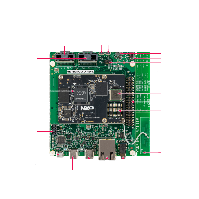
GET TO KNOW THE i.MX 8M NANO EVK
Display: MIPI-DSI Display: MIPI-DSI
Camera: MIPI-CSICamera: MIPI-CSI
CPU BoardCPU Board
II22C Connector C Connector
USB MicroB USB MicroB
Debug PortDebug Port
2
Type C Type C
Type C Type C
Port2Port2
EthernetEthernet Audio Audio
LineoutLineout
Port1Port1
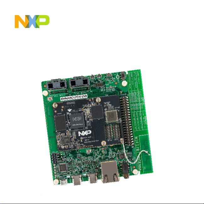
Figure 1: Top view i.MX 8M Nano EVK board
On/Off ResetOn/Off Reset
IR ReceiverIR Receiver
Power SwitchPower Switch
JTAGJTAG
NXP Wi-Fi/BT NXP Wi-Fi/BT
ModuleModule
Expansion Expansion
ConnectorConnector
BOOT Switches BOOT Switches
Wi-Fi/BT AntennaWi-Fi/BT Antenna
Page 3
QUICK START GUIDE i.MX 8M APPLICATIONS PROCESSOR FAMILY
GET TO KNOW THE i.MX 8M NANO EVK CONTINUED
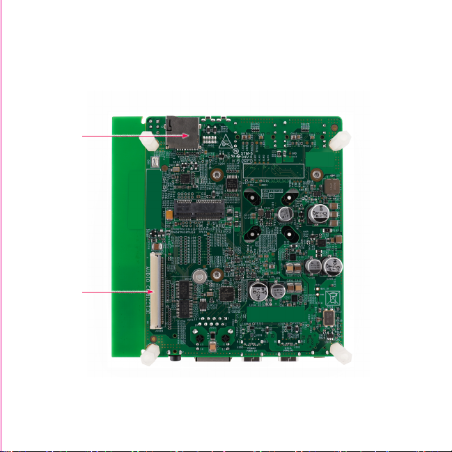
MicroSD Card MicroSD Card
ConnectorConnector
Audio Board Audio Board
ConnectorConnector
Figure 2: Back view i.MX 8M Nano EVK board
Page 4
GET TO KNOW THE i.MX 8M NANO EVK CONTINUED
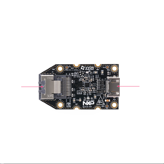
Mini SAS Mini SAS
connectorconnector
4
Figure 3: MIPI-DSI to HDMI Adaptor Card (included in
the EVK) Note: (Color of the adaptor card may differ)
HDMI HDMI
connectorconnector
Page 5

QUICK START GUIDE i.MX 8M APPLICATIONS PROCESSOR FAMILY
ABOUT THE i.MX 8M NANO EVK
The i.MX 8M Nano applications processor is a member of the i.MX 8M family of
products focused on delivering advanced media and machine learning experience
combining state-of-the-art capabilities with high-performance processing optimized for
low-power consumption.
FEATURES
Compute Module:
• i.MX 8M Nano applications processor
with up to five cores:
– 4× Arm® Cortex®-A53
– 1× Arm® Cortex®-M7
• LPDDR4 16-bit, 2 GB
• eMMC 5.1, 32 GB
• QSPI NOR flash, 32 MB
• NXP Power Management IC (PMIC)
• NXP Wi-Fi 802.11a/b/g/n/ac and BT5.0
Base Board:
• MicroSD card connector
• Two Type-C connectors:
• Port1 is USB2.0 Type-C connector
• Port2 is the only power supply port
• 1 Gbps Ethernet
• Mini-SAS MIPI-DSI connector for
display
• Mini-SAS MIPI-CSI connector for
camera
• USB to serial converter for debug
• Infrared receiver
• LEDs for power indication and generalpurpose use
• 3.5 mm audio jack for amplified speakers
5
Page 6

GETTING STARTED
Unpack the Kit
The i.MX 8M Nano EVK (8MNANOLPD4EVK) is shipped with the items listed in
Table 1. Ensure the items are available in
the EVK box.
Table 1 Kit Contents
ITEM DESCRIPTION
EVK Board i.MX 8M Nano EVK
IMX-MIPI-HDMI
Accessory Card
Power Supply
Mini-SAS cable 8" mini-SAS cable
USB Type-C
Cable
USB micro-B
Cable
USB Type-C to A
Adapter
Software
Documentation Quick Start Guide
6
MIPI-DSI to HDMI adapter board
USB Type C 45W Power Delivery
Supply, 5V/3A; 9V/3A; 15V/3A;
20V/2.25A supported
Cable – Assembly, USB 3.0, Type-C
Male to Type-A Male
Cable – Assembly, USB 2.0, Type-A
Male to Micro-B Male
Adapter – USB 3.0, Type-C Male to
Type-A Female
Android BSP image programmed
in eMMC
Prepare Accessories
The following items in Table 2 are
recommended to run the i.MX 8M Nano
EVK.
Table 2 Customer Supplied
Accessories
ITEM DESCRIPTION
HDMI Display
HDMI Cable
Mouse USB Mouse
USB HUB 2 or 4 port USB Hub
HDMI display that supports a minimum
resolution of 1080P60.
HDMI cable to connect the HDMI board
to HDMI display
Page 7

QUICK START GUIDE i.MX 8M APPLICATIONS PROCESSOR FAMILY
GETTING STARTED CONTINUED
Download Software and Tools
Installation software and documentation
are available at www.nxp.com/
imx8mnanoevk. The following are
available on the website:
Table 3 Software and Tools
ITEM DESCRIPTION
Documentation
Software
Development
Demo Images
• Schematics, layout and Gerber files
• i.MX 8M Nano EVK Board Hardware
User’s Guide
• Quick Start Guide
• Hardware Design Guide
• Power Consumption Measurement
Linux BSPs, Android BSPs
Copy of the latest Linux and Android BSP
images that are available to program on
to the eMMC or SD Card.
i.MX 8M Nano software can be found at
nxp.com/imxsw.
77
Page 8

SETTING UP THE SYSTEM
The following will describe how to run
the pre-loaded Android image on the
i.MX 8M Nano EVK.
Confirm Boot
1
Switches
The boot switches should be set to boot
from the eMMC. Only SW1101[1-4] are
used for boot. See table below
BOOT
DEVICE
eMMC/uSDHC3 0100XXXXXX XXXXXXXXXX
Note: 1 = ON 0 = OFF X = Don’t Care
SW1101 SW1102
Connect USB
2
Debug Cable
Connect the micro-B end of a USB cable
into debug port J901. Connect the other
end of the cable to a PC acting as a host
terminal. Two UART connections will
appear on the PC, one for M7 core, one
for A53 core. The console print will output
on “Enhanced COM port,” which can be
found in “Device Manager” of the PC.
8
If the serial port is not recognized,
download and install updated drivers as
listed in the section Debug Serial Console
below.
Open the terminal window (i.e., Hyper
Terminal or Tera Term), choose the COM
port number that corresponds to the
“Enhanced COM port” or the highest
numbered port and apply the following
configuration.
• Baud rate: 115200
• Data bits: 8
• Parity: None
• Flow control: None
Page 9

QUICK START GUIDE i.MX 8M APPLICATIONS PROCESSOR FAMILY
SETTING UP THE SYSTEM CONTINUED
Connect HDMI
3
Display
The MIPI-DSI to HDMI accessory card and
mini SAS cable are needed for evaluating
HDMI.
Connect the mini-SAS cable to J801
on the EVK (MIPI DSI Connector) and
connect the other end to J5 on the MIPI
to HDMI accessory card. Connect an
HDMI cable to J2 (HDMI port) on the MIPI
to HDMI accessory card and connect the
other end to a HDMI display panel.
Figure 4: Mini-SAS cable connected to the miniSAS connector (J5) on the MIPI-DSI to HDMI
accessory board.
Note: Color may differ
Connect
4
Mouse
Connect the mouse to J301 (USB Type-C
Port1) through the USB Type-C to A
adapter.
Connect Power
Supply
5
Connect the USB Type-C plug of the
Power Supply to J302 (USB Type-C Port2),
then power up the board using switch
SW101.
Use only J302 for power delivery to the
board.
Board Boot
6
Up
As the board boots up, you will see 4
penguins appear in the upper left-hand
corner of the monitor, and then you will
see the Android logo, then the Android
desktop. Congratulations, you are up and
running.
99
Page 10

ADDITIONAL INFORMATION
Boot Switches
SW1101[1-4] are the boot configuration switches, the default boot device is eMMC/
uSDHC3, as shown in Table 4. If you want to try other boot devices, you need to
change the boot switches to corresponding values as listed in Table 4.
Table 4 Boot Device Settings
BOOT DEVICE SW1101 SW1102
eMMC/uSDHC3 0100XXXXXX XXXXXXXXXX
MicroSD/uSDHC2 1100XXXXXX XXXXXXXXXX
QSPI NOR Flash 0110XXXXXX XXXXXXXXXX
Serial Download Mode 1000XXXXXX XXXXXXXXXX
Note: 1 = ON 0 = OFF X = Don’t Care
Debug Serial Console
Windows users may need to update the serial drivers on your computer. The drivers
can be found at https://www.ftdichip.com/Drivers/VCP.htm
10
Page 11

QUICK START GUIDE i.MX 8M APPLICATIONS PROCESSOR FAMILY
ADDITIONAL INFORMATION CONTINUED
Do more with Accessory boards
MX8-DSI-OLED1:
MIPI MINI-SAS OLED DISPLAY
Use this OLED display for touchscreen support.
MINISASTOCSI:
MIPI-CSI CAMERA MODULE
Use this camera MIPI-CSI camera module for machine
vision, video streaming and recording .
SUPPORT
Visit www.nxp.com/support for a list
of phone numbers within your region.
WARRANTY
Visit www.nxp.com/warranty for
complete warranty information.
1111
Page 12

This device complies with Part 15 of the FCC Rules. Operation is subject to the following two conditions:
(1) This device may not cause harmful interference, and
(2) This device must accept any interference received, including interference that may cause undesired operation.
Attention that changes or modification not expressly approved by the party responsible for compliance could void the user’s
authority to operate the equipment.
Note: This product has been tested and found to comply with the limits for a Class B digital device, pursuant to Part 15 of the
FCC Rules. These limits are designed to provide reasonable protection against harmful interference in a residential installation.
This product generates, uses, and can radiate radio frequency energy and, if not installed and used in accordance with the
instructions, may cause harmful interference to radio communications. However, there is no guarantee that interference will not
occur in a particular installation. If this product does cause harmful interference to radio or television reception, which can be
determined
by turning the equipment off and on, the user is encouraged to try to correct the interference by one or more of the following
measures:
—Reorient or relocate the receiving antenna.
—Increase the separation between the equipment and receiver.
—Connect the equipment into an outlet on a circuit different from that to which the receiver is connected.
—Consult the dealer or an experienced radio/TV technician for help.
This equipment should be installed and operated with a minimum distance 20cm between the radiator and your body.
The following information is provided per Article 10.8 of the Radio Equipment Directive 2014/53/EU:
(a) Frequency bands in which the equipment operates.
(b) The maximum RF power transmitted.
PN RF TECHNOLOGY (A) FREQ RANGES (EU) (B) MAX TRANSMITTED POWER
WLAN 2.4 GHz Mode 802.11b/g/n 2412 MHz – 2472 MHz 17.61dBm
8MNANOLPD4EVK
EUROPEAN DECLARATION OF CONFORMITY (Simplified DoC per Article 10.9 of the Radio Equipment Directive 2014/53/
EU)
This apparatus, namely 8MNANOLPD4-EVK, conforms to the Radio Equipment Directive 2014/53/EU.
The full EU Declaration of Conformity for this apparatus can be found at this location: www.nxp.com/i.MX8MNANO
WLAN 5 GHz Mode 802.11a/n/ac 5180 MHz – 5700 MHz 19.78dBm
BLE 2402 MHz – 2480 MHz 6.09dBm
BT BR/EDR 2402 MHz – 2480 MHz 9.59dBm
www.nxp.com/iMX8MNANOEVK
NXP and the NXP logo are trademar ks of NXP B.V. All other product or service names are the proper ty of their
respective owners. © 2020 NXP B.V.
Document Number: 8MNANOLPD4EVKQSG REV 0
Agile Number: 926-38821 Rev A
 Loading...