

Page 1

Global Position System
Low Noise Amplifier
GPS, LNA, Sensitivity, Jamming,
Cohabitation, TTFF
This White Paper explains why an external low noise amplifier results in a better performance.
Next generation mobile handsets will be equipped with GSM, WLAN, Bluetooth and GPS.
Integrating all these functionality onto one printed circuit board gives housing problems or
cohabitation challenges. Some of them can be solved easily at low cost but others cannot.
In this paper the GPS and its cohabitation with GSM and WCDMA will be explained.
1 GPS Integration Challenge
Currently people are using Personal Navigation Devices (PND)
to finding a location around the globe. Likewise for wireless
LAN, wherever you are, you want to have the Internet available.
Downside of this multi functionality is that you have to carry
many devices with you. For this reason mobile handset makers
start to integrate the GPS WLAN etc. into one device.
Referring to GPS, the received signal strength is very weak.
The satellites have an orbit altitude of 20200 km (90 degrees
elevation) from earth. It’s transmit power is 44.8 Watt at
1575.43 MHz and the antenna gain is 12 dBi. Assume that the
PND device has an antenna gain of 4 dBi. Then the received
signal power is -120 dBm using the free space loss model.
Including additional losses (atmospherically, antenna) the
received power is -125 dBm. While the noise power in the
system bandwidth (2.046 MHz) is -110 dBm! But due to the
modulation scheme, which is direct spread-spectrum there is
a processing gain of 43 dB. In fact signals can be recovered
theoretically till -110-43=-153 dBm. In order to improve quality
of services the received power strength requirement will be
several dB above the theoretical level. For instance, during
acquisition the received power required is -135 dBm and for
tracking -147 dBm.
For cohabitation it is important to cope with the low signals
level at the GPS frequency. Unfortunately, this integration is not
straightforward. Putting different wireless functionality into one
housing is called cohabitation. Compare this with interpersonal
relationship you have to put in effort in to make it happen.
Page 2
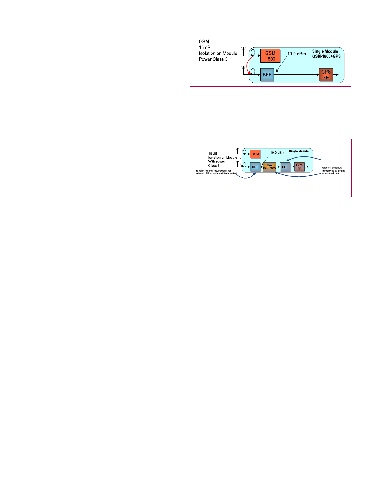
Figure 1 depicts an example of GSM and GPS cohabitation.
Suppose that the GSM transmitter transmits at 1800 MHz at
a power level of +36 dBm (4 Watt). The GPS receiver receives
GPS signals at 1575.42 MHz (L1 frequency) at a power level of
-125 dBm (about 0.1 fWatt). The isolation between the GSM
output and the GPS’s receiver input is approx. 15 dB. Leaving
21 dBm of GSM power at the GPS receive input.
Block diagram of GSM and GPS integrated on one PCB
Fig. 1
Filtering will help to reduce the GSM power level at the GPS
receiver’s input, see Fig 2, but will increase the noise level,
which reduces the GPS receiver sensitivity. High attenuation
filters have high insertion losses. Next to this the wideband
noise emission from the power amplifier of the GSM cannot be
filtered out, because it is present directly in the GPS band.
Finally, the GPS antenna might be separated far away from the
GPS receiver IC. Long PCB tracks results in an increased noise
level, which reduces the GPS receiver sensitivity as well. Note that
integrated GPS antennas have often low antenna gains (-6 dBi).
Cohabitation gives four problems to solve:
} Reduced GPS receiver sensitivity due to high filter losses to
attenuate out of band jamming signals (GSM, DCS, WCDMA)
to avoid overdriving the Low Noise Amplifier (LNA) and
improve out of band O-IIP3
} Cross modulation that corrupts GPS reception
} Wideband noise power generate by jamming PA
} Antenna GPS receiver separation
GSM transmits at class 3 (+36 dBm). At the GPS antenna input the received GSM power is 21
dBm. The band pass filter attenuates the GSM signal with 40 dB. Leaving –19 dBm at the input
of the GPS front-end IC
External LNA with BPF filters and GPS front end receiver
Fig. 2
2 GPS and GSM-1800 Cohabitation
GSM-1800 uses 1710–1785 MHz to send information from
the mobile station to the base transceiver station (uplink) and
1805–1880 MHz for the other direction (downlink), providing 374
channels (channel numbers 512 to 885). Duplex spacing is 95 MHz.
What will the end user experience when using an external LNA?
Improved sensitivity results in a shorter time to first fix (TTFF).
TTFF definition is the specification detailing the time required
for a GPS receiver to acquire satellite signals and navigation
data, and calculate a position solution. The latter is called a fix.
Long TTFF results in an increased frustration level of the users.
This long TTFF can be improved by using an external LNA.
Resume, GPS receivers suffer a lot from receiver desensitization
if a neighbor jamming signal(s) is (are) present. This white
paper concentrates mostly on problem one and two. Problem
three can be solved by applying GPS blanking during Tx burst.
Problem four is solved by placing the LNA as close as possible
to the GPS receive antenna or use an active antenna with a high
gain LNA.
GSM-1800 is also called DCS (Digital Cellular Service) in the United
Kingdom, while being called PCS in Hong Kong (not to mix up with
GSM-1900 which is commonly called PCS in the rest of the world.)
According to the 3GPP TS 45.005 V8.3.0 (2008-11) there are
three power classes defined for GSM-1800.
These power classes are:
Class 1: 1 Watt or (+30 dBm),
Class 2: 0.25 Watt or (+24 dBm) and
Class 3: 4 Watt or (+36 dBm).
In case of GSM-1800 cohabitation, proper filtering and
proper amplifier design can solve problems 1 and 2. The NXP
BGU7005 LNA has special properties to improve the GPS
receiver sensitivity.
Page 3

2.1 Cross modulation that corrupts GPS reception
The NXP BGU7005 can cope with strong GSM jamming signals
while maintaining its low noise figure of 1.1 dB. In fact the
BGU7005 improves its immunity at the GSM-1800 frequency,
this results in an improved out of band input third order
intercept point (IIP3) linearity, +10 dBm. Poor out of band IIP3
performance of an external LNA gives cross-modulation (xmod)
that corrupts GPS reception.
Fig 3 shows the BGU7005 in a front-end module with pre- and
post filtering. Pre-filtering is required to reduce the GSM 1800
transmit power to avoid that the LNA will go into compression.
Post-filtering is needed to protect the integrated LNA in the
GPS IC.
Suppose that the PCS-1900 jammer is at one meter distance of
the GPS receive antenna. In this case the received power at the
GPS receive antenna is -19.8 dBm where the antenna gain for
PCS-1900 is 0 dBi and for GPS receiver -6 dBi. This PCS-1900
signal together with GSM-1800 signal will give cross modulation
at the GPS frequency due to third order intermodulation.
Suppose that the GSM-1800 transmit frequency f1=1713 MHz
and PCS-1900 transmit frequency f2=1851 MHz. GSM-1800 is
transmitting at +36 dBm and the PCS is transmitting at
+24 dBm. The out of band third order intercept point frequency
can be found to be f3rd =2*f1-f2=1575 MHz. This is exactly
the GPS frequency band. But the amplitude of this component
depends heavily on the linearity of the LNA.
The powers at the input of the first BPF are +21 dBm for GSM,
and -19.8 dBm for PCS, respectively at one meter distance.
Suppose that the filter attenuates the signals with 40 dB. Then
at the input of the LNA the signal powers are -19 dBm and
-59.8 dBm, respectively. The LNA has an out of band IIP3 of
+10 dBm, which gives an intermodulation level at the input of
the LNA (at the GPS frequency) of -117.8 dBm. If the GPS signal
is at -125 dBm then the Jamming to Signal ratio J/S can be
maximum 35.3 dB! This is at the edge of the GPS requirement
regarding narrow band jamming signals.
Block diagram of GSM cohabitation with NXP’s BGU7005
Fig. 3
GSM-1800 mobile transmit frequency range is 1710 – 1785 MHz power class 3 (+36 dBm) and
PCS-1900 (UMTS-FDD) mobile transmit frequency range 1850 -1910 MHz jammer power class 3
(+24 dBm) (3GPP TS 25.101).
2.2
Wideband noise power generate by jamming PA
Problem 3 cannot be solved by simply filtering because the
wide band noise resulting from the GSM PA falls directly in
the GPS band. Fortunately the GSM radio interface has a time
division duplex (TDD) mechanism. Implying that the transmit
burst and the receive burst are shifted in time. During receive
the GSM cannot transmit and vice versa. This feature of the
TDD behavior is used in the cohabitation problem 3.
The wide noise of the GSM is specified to be -79 dBm in 30kHz
bandwidth from 6 MHz onwards or -124 dBm/Hz. The frequency
difference between GSM 1800 and GPS is 135 MHz. This
translates to a total wide band noise power in the GPS band
of -61 dBm!
During transmit mode of the GSM the GPS receiver is switched
off. In the measurement engine of the GPS receiver an
extrapolation algorithm is used for location calculation. It is
assumed that the GPS user’s location change is small. For better
position accuracy it is desired that the GPS receiver is always on
and reduce the number of blanking intervals. Therefore blanking
is not used in case of cross modulation.
The BGU7005 is equipped with a shutdown pin where the
LNA can be switched on or off also called blanking (software
blanking is possible as well). Blanking speed of the BGU7005
is 1 MHz.
Page 4

3 GPS and UMTS-FDD Cohabitation
In contrast with GSM, UMTS-FDD (WCDMA) has a frequency
division duplex (FDD) operation, which implies that both the
transmitter and receiver are active simultaneously. Therefore
blanking of the GPS receiver does not make sense.
In the WCDMA case the GPS receiver relies on the pre- and
post filtering. Insufficient attenuation of the WCDMA signals
results in a saturated LNAv
3.1
Cross modulation that corrupts GPS reception
In order to solve this out of band linearity a band pass filter with
sufficient attenuation is placed in front of the external LNA.
Suppose that a band pass filter has an attenuation of 40 dB for the
out of band signals. Then by using the previous input powers, this
results in an IM3 level of –140 dBm.
The continuous wave (CW) jammer to (GPS) signal ratio J/S can
be maximum +30 dB. This implies that for a typical power level of
GPS signal of -125 dBm the maximum jamming signal is -95 dBm.
This results in a minimum out of band IIP3 requirement of +57 dBm
having the above mentioned power levels. Often a margin of 3 dB
is used, resulting in an out of band IIP3 of +60 dBm.
A saturated LNA (or often called LNA is in compression) gives
distortion in the GPS frequency band. Fig 6 shows the worldwide
frequency spectrum allocation. In North America, Europe, Africa,
China and Australia the 1710 MHz band and the 1810 MHz
band are occupied with UMTS-FDD and GSM communication
systems. Both having high transmit powers. The out of band inter
modulation of the third order of the LNA given the 1710 MHz
frequency and 1810 MHz frequency gives distortion components
in the GPS bands.
Suppose f1=1713 MHz (UMTS-FDD 1800) and f2=1851 MHz
(UMTS-FDD 1900) then the third order component can be found
to be f3rd =2*f1-f2=1575 MHz. This is exactly the GPS frequency
band. But the amplitude of this component depends heavily on
the linearity of the LNA. See also Fig 4.
The typical power level of the GPS signal is -125 dBm. It is allowed
that the out of band intermodulation product of order 3 (IM3)
power level coming from a two tone is to be 11.7 dB higher than
the GPS signal level therefore the out of band linearity of the LNA
should be about 100 dBm without filtering and including 10 dB
antenna isolation. Of course this is not feasible. But in case of
selectivity in front of the LNA the linearity requirement will relax.
The input 1 dB compression point is of the LNA -9 dBm at 1.8 V.
The max transmit mode of GSM is +36 dBm and the antenna
isolation is 15 dB. The minimal attenuation required by the filter to
prevent that the LNA is going into compression at UMTS frequency
is (36-15)-(-9) =30 dB.
Fig 5 shows the NXP’s front end module with the BGU7005. It can
clearly been seen that the cumulative out of band IIP3 is above 60
dBm. The minimum out of band requirement of 57 dBm is easily
met. Moreover the cumulative noise is 2.3 dB. As extra feature the
BGU7005 can be implemented in the application as low external
component count or as low current consumption.
Interference into GPS receiver for UMTS-FDD 1800 and
UMTS-FDD 1900
Fig. 4
NXP’s front-end module linearity performance at the
antenna input
Consequently, the out of band input IP3 measured for the
BGU7005 is +9 dBm. But the GPS specification requires that the
out of band linearity should be better than +9 dBm. Suppose that
the UMTS 1800 jammer is 3 meters away from the GPS receive
antenna and that the UMTS 1900 transmitter transmits at +30
dBm. The received power level at the GPS antenna from the UMTS
1800 jammer transmitting at +24 dBm is -29.3 dBm. The antenna
gain for the UMTS 1800 is -10 dBi giving -39.3 at the input of the
LNA. In this case the IM3 level is -24.3 dBm at GPS L1 frequency. A
GPS signal at -125 dBm will be heavily distorted.
Fig. 5
Page 5

Worldwide frequency spectrum allocation between 800
and 2000 MHz.
and linearity is poor (out of band IIP3 < -16 dBm). To improve
the GPS receiver sensitivity and cohabitation (is mainly linearity)
issues often an external filter is applied. To compensate for GPS
receiver sensitivity loss an external LNA is placed after the filter.
Why buy LNAs from NXP?
NXP has a high performance BICMOS SiGe:C process
having Ft/Fmax of 180 GHz and having many, many years of
experience of small low cost package development.
The BGU7005 has:
} Fast switching shutdown function.
} Small form factor, BGU7005 uses only 2 external components
(1x Coil and 1x decoupling capacitor)
Fig. 6
3.2
Wideband noise power generated by jamming PA
Problem 3 cannot be solved by simply filtering, because the wide
band noise resulting from the WCDMA PA is directly in the GPS band.
The WCDMA radio interface has a frequency division duplex (FDD)
mechanism. Implying that the transmit burst and the receive burst are
in frequency shifted. Transmitting and receiving happens at the same
time. Blanking is not possible in this case and cannot solve problem 3.
During the transmit mode of the GSM, the GPS receiver is
switched off. In the measurement engine of the GPS receiver
an extrapolation algorithm is used for location calculation. It is
assumed that the GPS user’s location change is small.
The spurious level is defined in 3GPP TS 25.101 version 8.4.0
Release 8 and is specified to be -79dBm in 100 kHz measurement
bandwidth (absolute requirement) or -129 dBm/Hz. Resulting in
-66 dBm noise power in GPS band! Fortunately the user
equipment is transmitting at a lower power compared to GSM.
In fact wideband noise is not really a problem and therefore
blanking is not required.
4 Conclusions
Why buy LNA at all?
A lot of GPS measurement engine ICs have an integrated CMOS
LNA, which has a moderate RF performance. NF is relatively high
} Total Front–End requires only 4 components (2x BPF, 1x Coil
and 1x decoupling capacitor
} Front-End end reference evaluation module which has
~3x3 mm2 with a total of 5 components
} Lowest cost (cost effective package and low cost SiGe:C
process)
} Re-configurable application lowest current vs. out of band
linearity
} Knowledgeable application support.
Common misunderstandings of GPS external LNA
} In band input IP3 not important since GPS signal is very weak
(-130 dBm)
} High gain is not important for integration into a mobile
phone. Internal LNA of GPS IC will be overdriven
} BGU7005 is not aimed as active antenna LNA
Contents
1. GPS Integration Challenge 1
2. GPS and GSM-1800 Cohabitation 2
2.1 Cross modulation that corrupts GPS reception 3
2.2 Wideband noise power generate by jamming PA 3
3. GPS and UMTS-FDD Cohabitation 4
3.1 Cross modulation that corrupts GPS reception 4
3.2 Wideband noise power generate by jamming PA 5
4. Conclusions 5
5. Contents 6
www.nxp.com
© 2009 NXP B.V.
All rights reser ved. Reproduc tion i n whol e or in part is p rohibited witho ut the prio r wri tten consent of the co pyright owner.
The informat ion pre sented in this docum ent do es not form part of an y quota tion or contr act, is beli eved to be accurate and
reliabl e an d may be chang ed wi thout notice. No liabilit y wi ll be acce pted by t he pu blisher for any conseque nce of it s us e.
Public ation thereo f does not convey n or imply any lic ense under pat ent- or other ind ustrial or in tellectual p roperty r ights.
Date of rel ease: May 200 9
Docum ent order numb er: 9397 750 16740
Printe d in the Netherl ands
 Loading...