

Page 1

GDFLIB User's Guide
ARM® Cortex® M7F
Document Number: CM7FGDFLIBUG
Rev. 4, 12/2020
Page 2

GDFLIB User's Guide, Rev. 4, 12/2020
2 NXP Semiconductors
Page 3

Contents
Section number Title Page
Chapter 1
Library
1.1 Introduction.................................................................................................................................................................... 5
1.2 Library integration into project (MCUXpresso IDE) ....................................................................................................8
1.3 Library integration into project (Keil µVision) ............................................................................................................. 16
1.4 Library integration into project (IAR Embedded Workbench) ..................................................................................... 24
Chapter 2
Algorithms in detail
2.1 GDFLIB_FilterExp.........................................................................................................................................................33
2.2 GDFLIB_FilterIIR1........................................................................................................................................................37
2.3 GDFLIB_FilterIIR2........................................................................................................................................................42
2.4 GDFLIB_FilterIIR3........................................................................................................................................................49
2.5 GDFLIB_FilterIIR4........................................................................................................................................................55
2.6 GDFLIB_FilterMA.........................................................................................................................................................62
GDFLIB User's Guide, Rev. 4, 12/2020
NXP Semiconductors 3
Page 4

GDFLIB User's Guide, Rev. 4, 12/2020
4 NXP Semiconductors
Page 5

Chapter 1
Library
1.1 Introduction
1.1.1 Overview
This user's guide describes the General Digital Filters Library (GDFLIB) for the family
of ARM Cortex M7F core-based microcontrollers. This library contains optimized
functions.
1.1.2
GDFLIB supports several data types: (un)signed integer, fractional, and accumulator, and
floating point. The integer data types are useful for general-purpose computation; they
are familiar to the MPU and MCU programmers. The fractional data types enable
powerful numeric and digital-signal-processing algorithms to be implemented. The
accumulator data type is a combination of both; that means it has the integer and
fractional portions.The floating-point data types are capable of storing real numbers in
wide dynamic ranges. The type is represented by binary digits and an exponent. The
exponent allows scaling the numbers from extremely small to extremely big numbers.
Because the exponent takes part of the type, the overall resolution of the number is
reduced when compared to the fixed-point type of the same size.
The following list shows the integer types defined in the libraries:
• Unsigned 16-bit integer —<0 ; 65535> with the minimum resolution of 1
• Signed 16-bit integer —<-32768 ; 32767> with the minimum resolution of 1
• Signed 32-bit integer —<-2147483648 ; 2147483647> with the minimum resolution
Data types
of 1
GDFLIB User's Guide, Rev. 4, 12/2020
NXP Semiconductors 5
Page 6
Introduction
The following list shows the fractional types defined in the libraries:
• Fixed-point 16-bit fractional —<-1 ; 1 - 2
• Fixed-point 32-bit fractional —<-1 ; 1 - 2
-15
> with the minimum resolution of 2
-31
> with the minimum resolution of 2
-15
-31
The following list shows the accumulator types defined in the libraries:
• Fixed-point 16-bit accumulator —<-256.0 ; 256.0 - 2-7> with the minimum
resolution of 2
• Fixed-point 32-bit accumulator —<-65536.0 ; 65536.0 - 2
resolution of 2
-7
-15
-15
> with the minimum
The following list shows the floating-point types defined in the libraries:
• Floating point 32-bit single precision —<-3.40282 · 1038 ; 3.40282 · 1038> with the
minimum resolution of 2
1.1.3
API definition
-23
GDFLIB uses the types mentioned in the previous section. To enable simple usage of the
algorithms, their names use set prefixes and postfixes to distinguish the functions'
versions. See the following example:
f32Result = MLIB_Mac_F32lss(f32Accum, f16Mult1, f16Mult2);
where the function is compiled from four parts:
• MLIB—this is the library prefix
• Mac—the function name—Multiply-Accumulate
• F32—the function output type
• lss—the types of the function inputs; if all the inputs have the same type as the
output, the inputs are not marked
The input and output types are described in the following table:
Table 1-1. Input/output types
Type Output Input
frac16_t F16 s
frac32_t F32 l
acc32_t A32 a
float_t FLT f
GDFLIB User's Guide, Rev. 4, 12/2020
6 NXP Semiconductors
Page 7

Chapter 1 Library
1.1.4 Supported compilers
GDFLIB for the ARM Cortex M7F core is written in C language or assembly language
with C-callable interface depending on the specific function. The library is built and
tested using the following compilers:
• MCUXpresso IDE
• IAR Embedded Workbench
• Keil µVision
For the MCUXpresso IDE, the library is delivered in the gdflib.a file.
For the Kinetis Design Studio, the library is delivered in the gdflib.a file.
For the IAR Embedded Workbench, the library is delivered in the gdflib.a file.
For the Keil µVision, the library is delivered in the gdflib.lib file.
The interfaces to the algorithms included in this library are combined into a single public
interface include file, gdflib.h. This is done to lower the number of files required to be
included in your application.
1.1.5
Library configuration
GDFLIB for the ARM Cortex M7F core is written in C language or assembly language
with C-callable interface depending on the specific function. Some functions from this
library are inline type, which are compiled together with project using this library. The
optimization level for inline function is usually defined by the specific compiler setting. It
can cause an issue especially when high optimization level is set. Therefore the
optimization level for all inline assembly written functions is defined by compiler
pragmas using macros. The configuration header file RTCESL_cfg.h is located in:
specific library folder\MLIB\Include. The optimization level can be changed by
modifying the macro value for specific compiler. In case of any change the library
functionality is not guaranteed.
Similarly as optimization level the High-speed functions execution suppport can be
enable by defined symbol RAM_OPTIM_LOW (RAM_OPTIM_MEDIUM or
RAM_OPTIM_HIGH) or disable by not defining any of these macrors. symbol
RTCESL_MMDVSQ_OFF in project setting described in the High-speed functions
execution suppport cheaper for specific compiler.
GDFLIB User's Guide, Rev. 4, 12/2020
NXP Semiconductors 7
Page 8

Library integration into project (MCUXpresso IDE)
1.1.6 Special issues
1. The equations describing the algorithms are symbolic. If there is positive 1, the
number is the closest number to 1 that the resolution of the used fractional type
allows. If there are maximum or minimum values mentioned, check the range
allowed by the type of the particular function version.
2. The library functions that round the result (the API contains Rnd) round to nearest
(half up).
1.2 Library integration into project (MCUXpresso IDE)
This section provides a step-by-step guide on how to quickly and easily include GDFLIB
into any MCUXpresso SDK example or demo application projects using MCUXpresso
IDE. This example uses the default installation path (C:\NXP\RTCESL
\CM7F_RTCESL_4.6_MCUX). If you have a different installation path, use that path
instead.
1.2.1
High-speed functions execution suppport
Some RT (or other) platforms contain high-speed functions execution support by
relocating all functions from the default Flash memory location to the RAM location for
much faster code access. The feature is important especially for devices with a slow Flash
interface. This section shows how to turn the RAM optimization feature support on and
off.
1. In the MCUXpresso SDK project name node or on the left-hand side, click Properties
or select Project > Properties from the menu. A project properties dialog appears.
2. Expand the C/C++ Build node and select Settings. See Figure 1-1.
3. On the right-hand side, under the MCU C Compiler node, click the Preprocessor
node. See Figure 1-1.
GDFLIB User's Guide, Rev. 4, 12/2020
8 NXP Semiconductors
Page 9

Chapter 1 Library
Figure 1-1. Defined symbols
4. On the right-hand side of the dialog, click the Add... icon located next to the Defined
symbols (-D) title.
5. In the dialog that appears (see Figure 1-2), type the following:
• RAM_RELOCATION — to turn the RAM optimization feature support on
If the define is defined, all RTCEL functions are put to the RAM.
Figure 1-2. Symbol definition
6. Click OK in the dialog.
7. Click OK in the main dialog.
The device reference manual shows how the__RAMFUNC(RAM) atribute works in connection
with your device.
GDFLIB User's Guide, Rev. 4, 12/2020
NXP Semiconductors 9
Page 10
Library integration into project (MCUXpresso IDE)
1.2.2 Library path variable
To make the library integration easier, create a variable that holds the information about
the library path.
1. Right-click the MCUXpresso SDK project name node in the left-hand part and click
Properties, or select Project > Properties from the menu. A project properties dialog
appears.
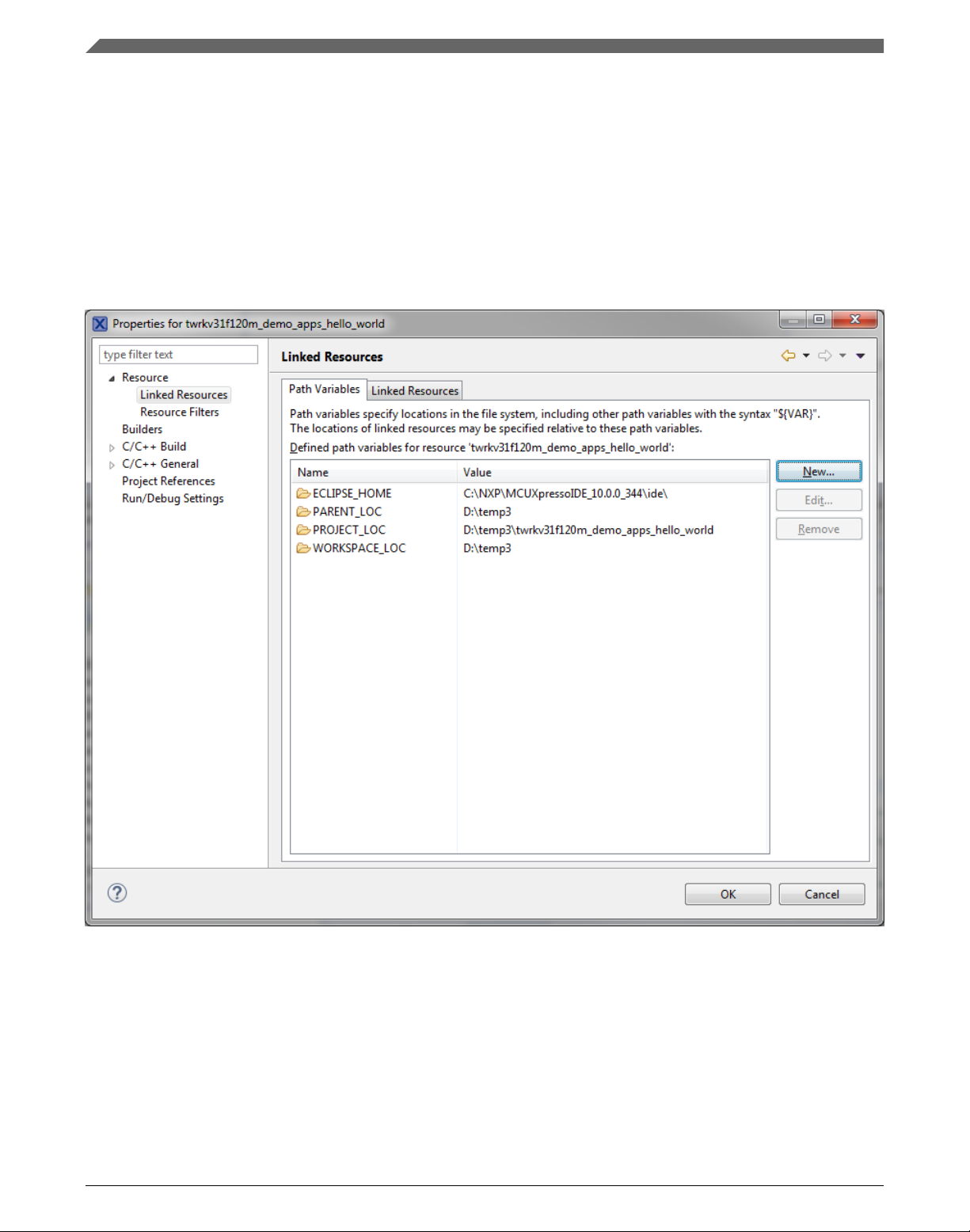
2. Expand the Resource node and click Linked Resources. See Figure 1-3.
Figure 1-3. Project properties
3. Click the New… button in the right-hand side.
4. In the dialog that appears (see Figure 1-4), type this variable name into the Name
box: RTCESL_LOC.
5. Select the library parent folder by clicking Folder…, or just type the following path
into the Location box: C:\NXP\RTCESL\CM7F_RTCESL_4.6_MCUX. Click OK.
GDFLIB User's Guide, Rev. 4, 12/2020
10 NXP Semiconductors
Page 11
Chapter 1 Library
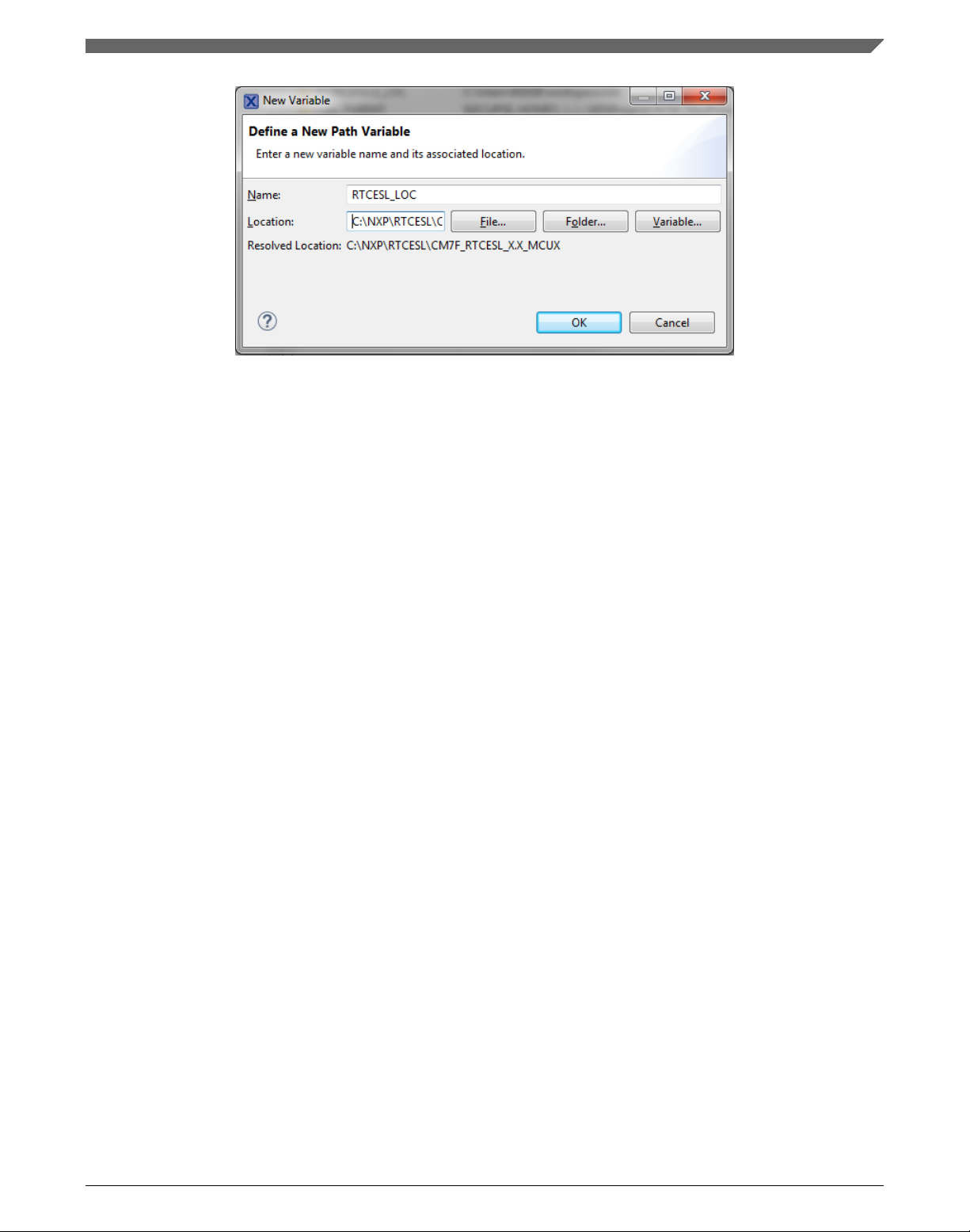
Figure 1-4. New variable
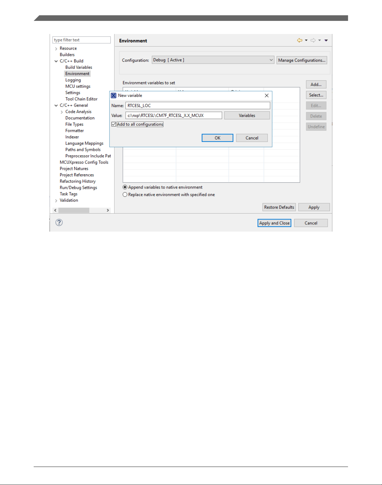
6. Create such variable for the environment. Expand the C/C++ Build node and click
Environment.
7. Click the Add… button in the right-hand side.
8. In the dialog that appears (see Figure 1-5), type this variable name into the Name
box: RTCESL_LOC.
9. Type the library parent folder path into the Value box: C:\NXP\RTCESL
\CM7F_RTCESL_4.6_MCUX.
10. Tick the Add to all configurations box to use this variable in all configurations. See
Figure 1-5.
11. Click OK.
12. In the previous dialog, click OK.
GDFLIB User's Guide, Rev. 4, 12/2020
NXP Semiconductors 11
Page 12
Library integration into project (MCUXpresso IDE)
Figure 1-5. Environment variable
1.2.3
Library folder addition
To use the library, add it into the Project tree dialog.
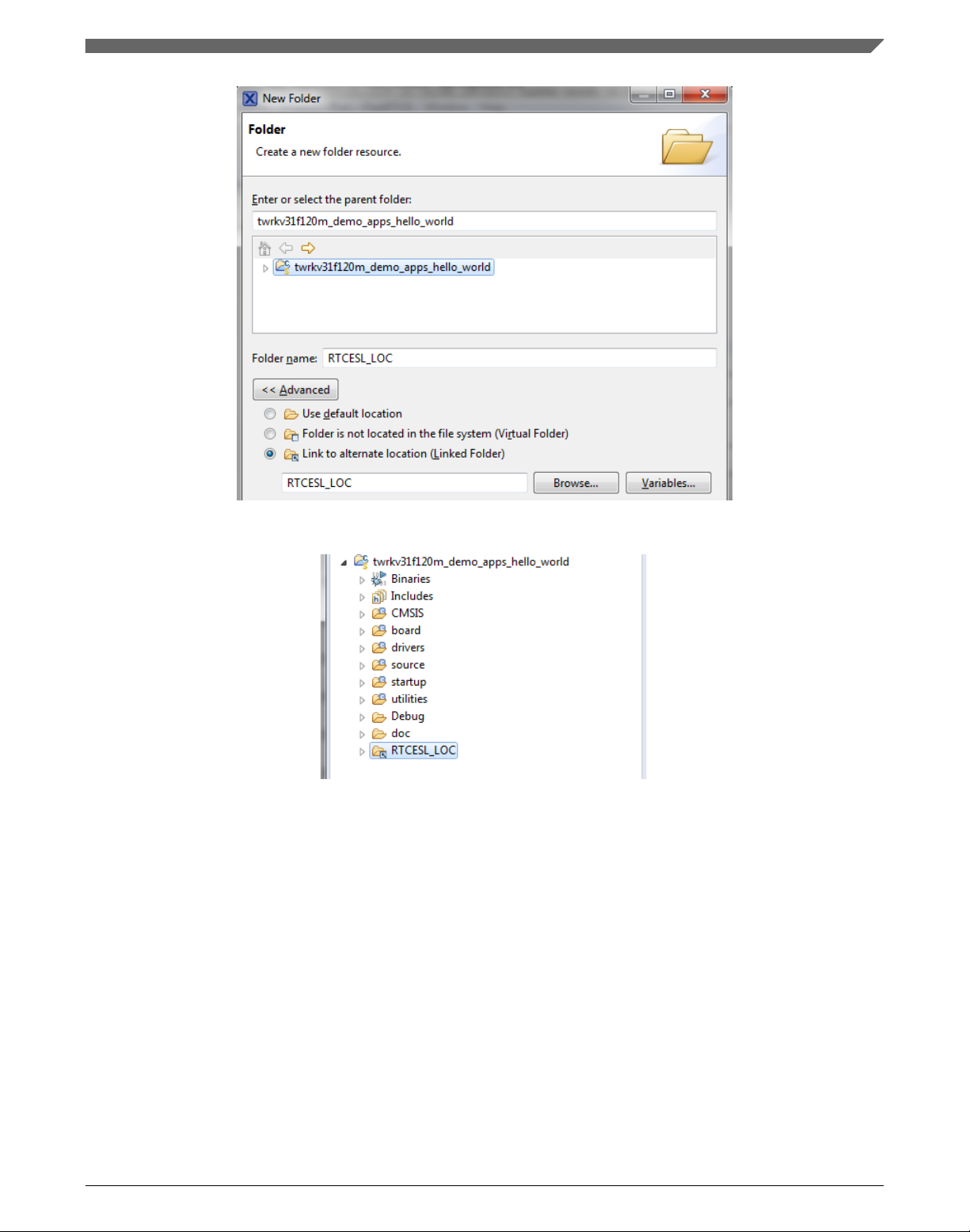
1. Right-click the MCUXpresso SDK project name node in the left-hand part and click
New > Folder, or select File > New > Folder from the menu. A dialog appears.
2. Click Advanced to show the advanced options.
3. To link the library source, select the Link to alternate location (Linked Folder)
option.
4. Click Variables..., select the RTCESL_LOC variable in the dialog, click OK, and/or
type the variable name into the box. See Figure 1-6.
5. Click Finish, and the library folder is linked in the project. See Figure 1-7.
GDFLIB User's Guide, Rev. 4, 12/2020
12 NXP Semiconductors
Page 13
Chapter 1 Library
Figure 1-6. Folder link
Figure 1-7. Projects libraries paths
1.2.4
Library path setup
GDFLIB requires MLIB to be included too. These steps show how to include all
dependent modules:
1. Right-click the MCUXpresso SDK project name node in the left-hand part and click
Properties, or select Project > Properties from the menu. The project properties
dialog appears.
2. Expand the C/C++ General node, and click Paths and Symbols.
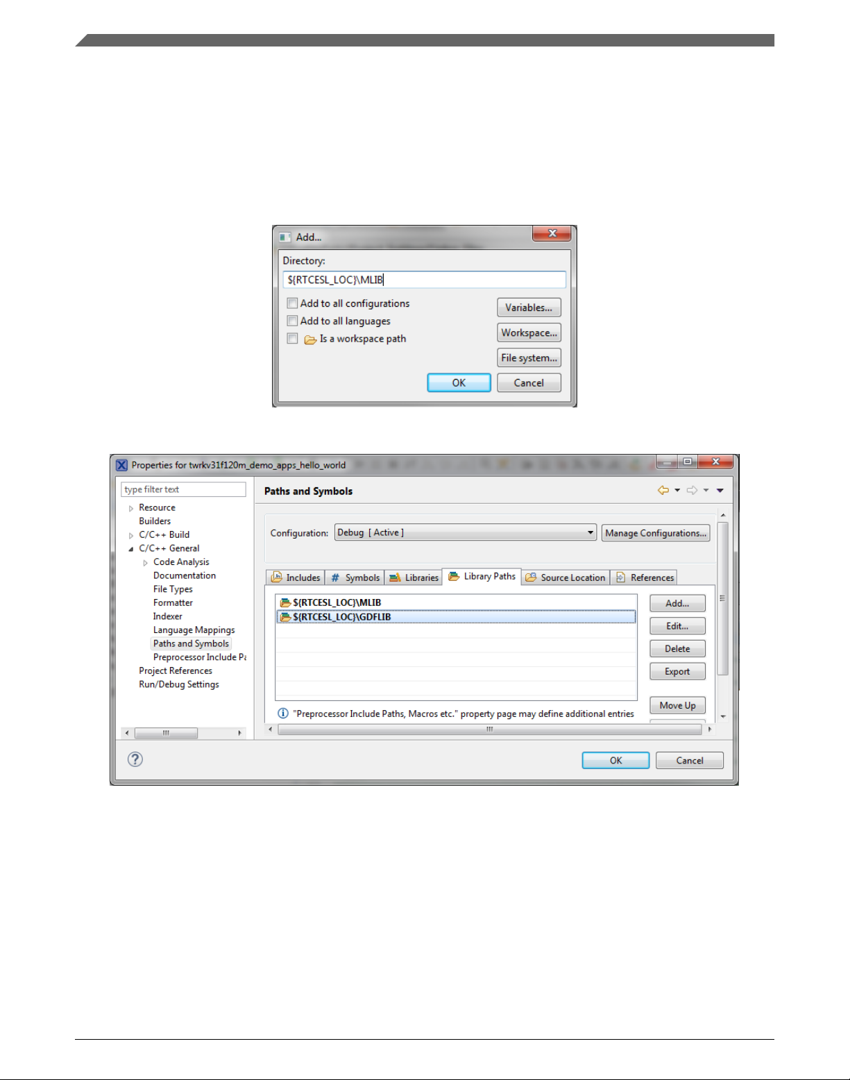
3. In the right-hand dialog, select the Library Paths tab. See Figure 1-9.
4. Click the Add… button on the right, and a dialog appears.
GDFLIB User's Guide, Rev. 4, 12/2020
NXP Semiconductors 13
Page 14
Library integration into project (MCUXpresso IDE)
5. Look for the RTCESL_LOC variable by clicking Variables…, and then finish the
path in the box by adding the following (see Figure 1-8): ${RTCESL_LOC}\MLIB.
6. Click OK, and then click the Add… button.
7. Look for the RTCESL_LOC variable by clicking Variables…, and then finish the
path in the box by adding the following: ${RTCESL_LOC}\GDFLIB.
8. Click OK, you will see the paths added into the list. See Figure 1-9.
Figure 1-8. Library path inclusion
Figure 1-9. Library paths
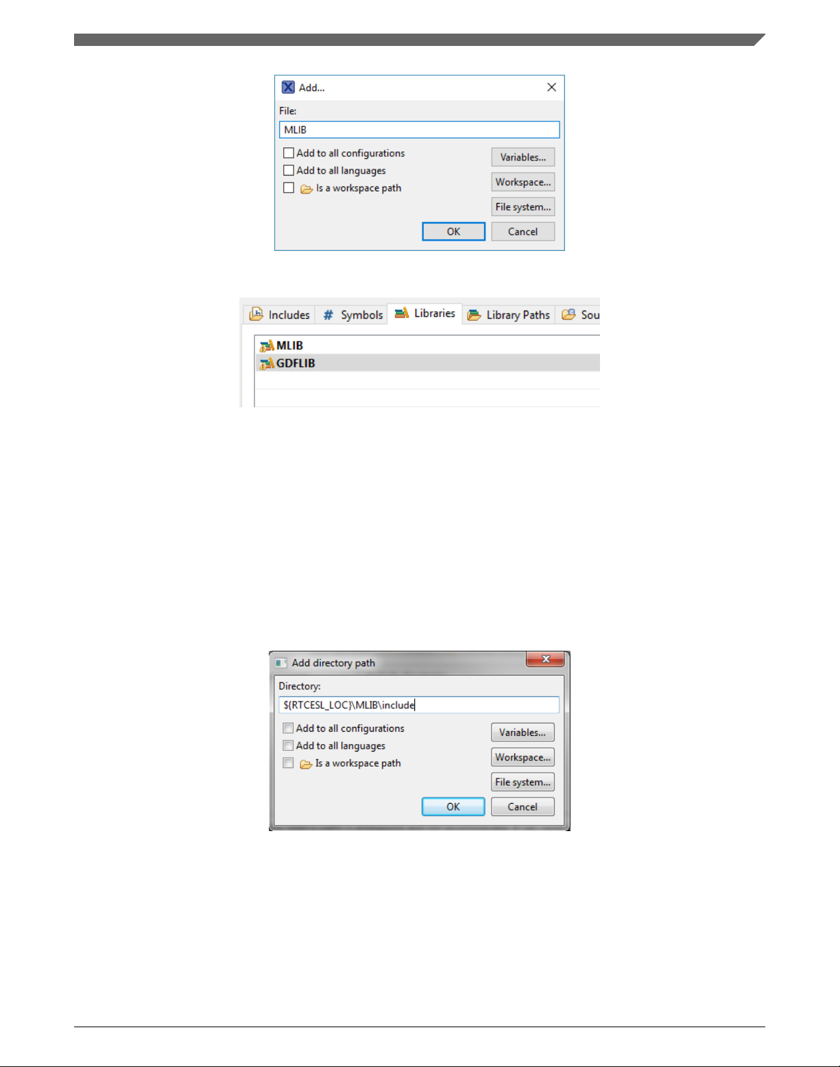
9. After adding the library paths, add the library files. Click the Libraries tab. See
Figure 1-11.
10. Click the Add… button on the right, and a dialog appears.
11. Type the following into the File text box (see Figure 1-10): :mlib.a
12. Click OK, and then click the Add… button.
13. Type the following into the File text box: :gdflib.a
14. Click OK, and you will see the libraries added in the list. See Figure 1-11.
GDFLIB User's Guide, Rev. 4, 12/2020
14 NXP Semiconductors
Page 15
Chapter 1 Library
Figure 1-10. Library file inclusion
Figure 1-11. Libraries
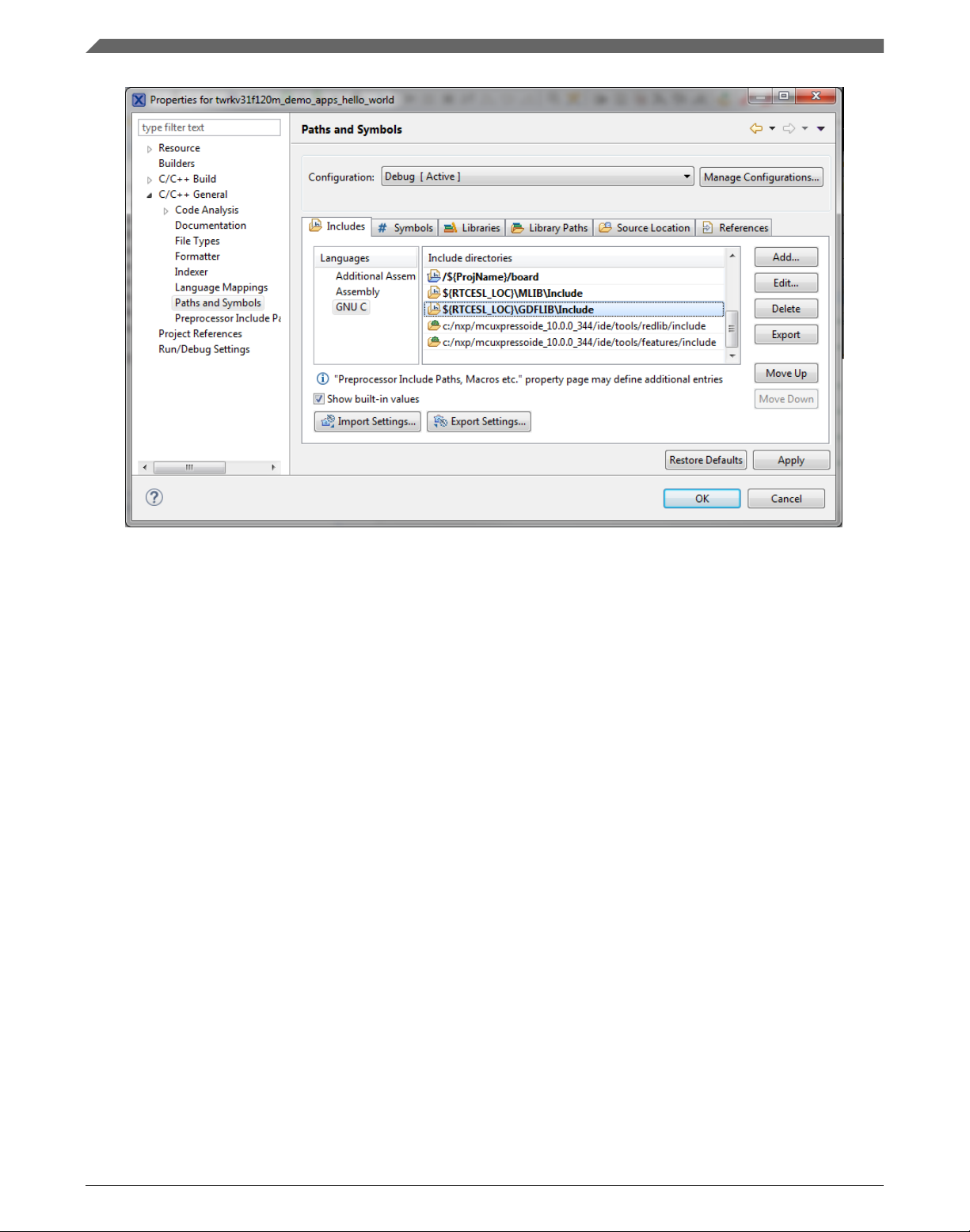
15. In the right-hand dialog, select the Includes tab, and click GNU C in the Languages
list. See Figure 1-13.
16. Click the Add… button on the right, and a dialog appears. See Figure 1-12.
17. Look for the RTCESL_LOC variable by clicking Variables…, and then finish the
path in the box to be: ${RTCESL_LOC}\MLIB\Include
18. Click OK, and then click the Add… button.
19. Look for the RTCESL_LOC variable by clicking Variables…, and then finish the
path in the box to be: ${RTCESL_LOC}\GDFLIB\Include
20. Click OK, and you will see the paths added in the list. See Figure 1-13. Click OK.
Figure 1-12. Library include path addition
GDFLIB User's Guide, Rev. 4, 12/2020
NXP Semiconductors 15
Page 16
Library integration into project (Keil µVision)
Figure 1-13. Compiler setting
Type the #include syntax into the code where you want to call the library functions. In
the left-hand dialog, open the required .c file. After the file opens, include the following
lines into the #include section:
#include "mlib_FP.h"
#include "gdflib_FP.h"
When you click the Build icon (hammer), the project is compiled without errors.
1.3
Library integration into project (Keil µVision)
This section provides a step-by-step guide on how to quickly and easily include GDFLIB
into an empty project or any MCUXpresso SDK example or demo application projects
using Keil µVision. This example uses the default installation path (C:\NXP\RTCESL
\CM7F_RTCESL_4.6_KEIL). If you have a different installation path, use that path
instead. If any MCUXpresso SDK project is intended to use (for example hello_world
project) go to Linking the files into the project chapter otherwise read next chapter.
GDFLIB User's Guide, Rev. 4, 12/2020
16 NXP Semiconductors
Page 17
Chapter 1 Library
1.3.1 NXP pack installation for new project (without MCUXpresso
SDK)
This example uses the NXP MKV58F1M0xxx22 part, and the default installation path
(C:\NXP\RTCESL\CM7F_RTCESL_4.6_KEIL) is supposed. If the compiler has never
been used to create any NXP MCU-based projects before, check whether the NXP MCU
pack for the particular device is installed. Follow these steps:
1. Launch Keil µVision.
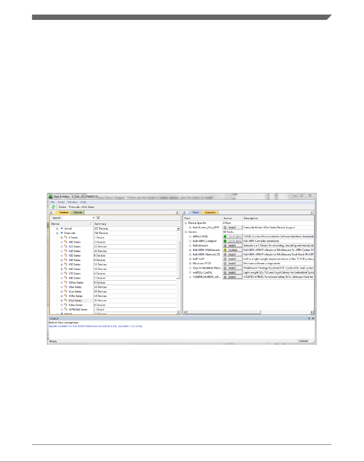
2. In the main menu, go to Project > Manage > Pack Installer….
3. In the left-hand dialog (under the Devices tab), expand the All Devices > Freescale
(NXP) node.
4. Look for a line called "KVxx Series" and click it.
5. In the right-hand dialog (under the Packs tab), expand the Device Specific node.
6. Look for a node called "Keil::Kinetis_KVxx_DFP." If there are the Install or Update
options, click the button to install/update the package. See Figure 1-14.
7. When installed, the button has the "Up to date" title. Now close the Pack Installer.
Figure 1-14. Pack Installer
1.3.2
New project (without MCUXpresso SDK)
To start working on an application, create a new project. If the project already exists and
is opened, skip to the next section. Follow these steps to create a new project:
1. Launch Keil µVision.
GDFLIB User's Guide, Rev. 4, 12/2020
NXP Semiconductors 17
Page 18
Library integration into project (Keil µVision)
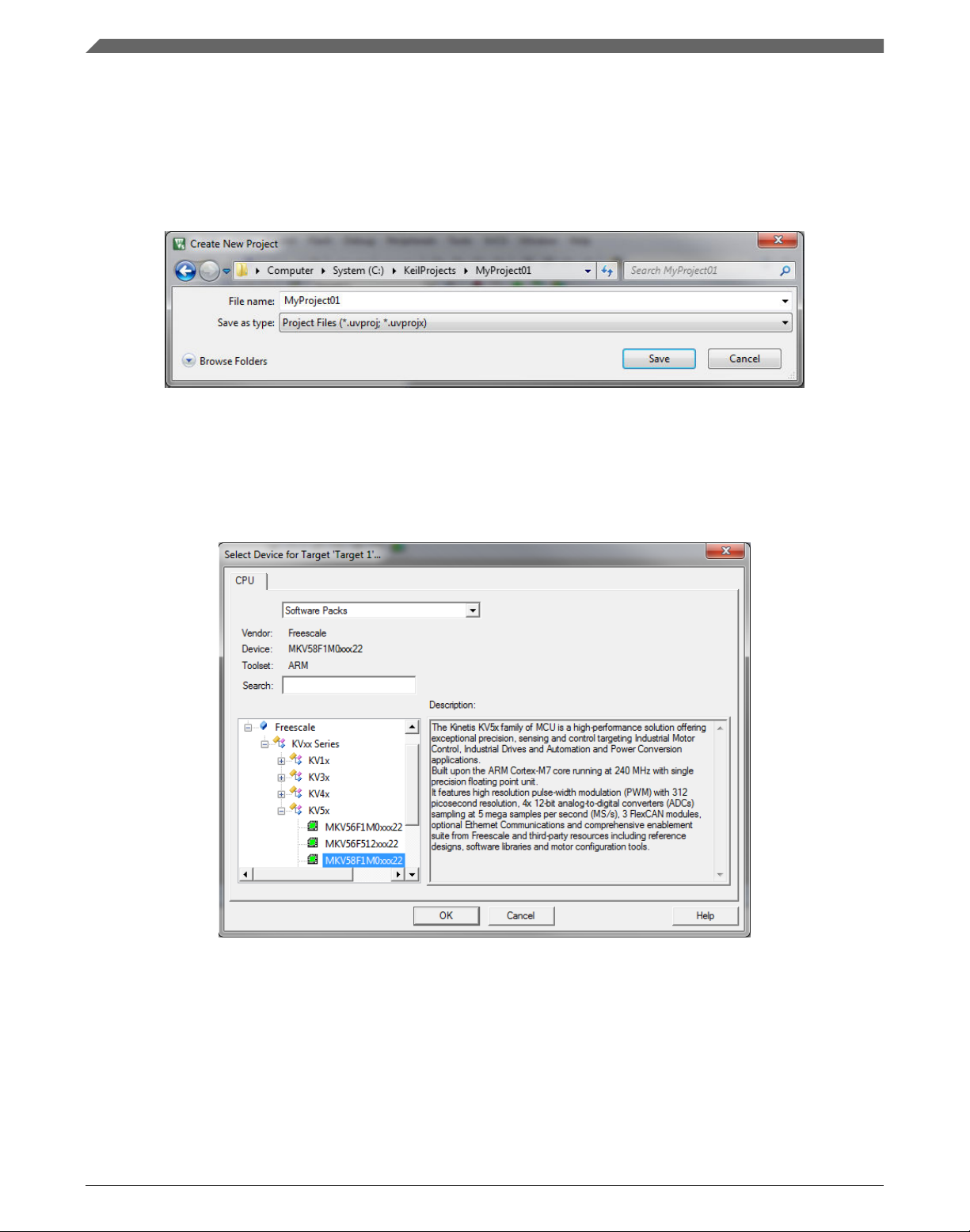
2. In the main menu, select Project > New µVision Project…, and the Create New
Project dialog appears.
3. Navigate to the folder where you want to create the project, for example C:
\KeilProjects\MyProject01. Type the name of the project, for example MyProject01.
Click Save. See Figure 1-15.
Figure 1-15. Create New Project dialog
4. In the next dialog, select the Software Packs in the very first box.
5. Type '' into the Search box, so that the device list is reduced to the devices.
6. Expand the node.
7. Click the MKV58F1M0xxx22 node, and then click OK. See Figure 1-16.
Figure 1-16. Select Device dialog
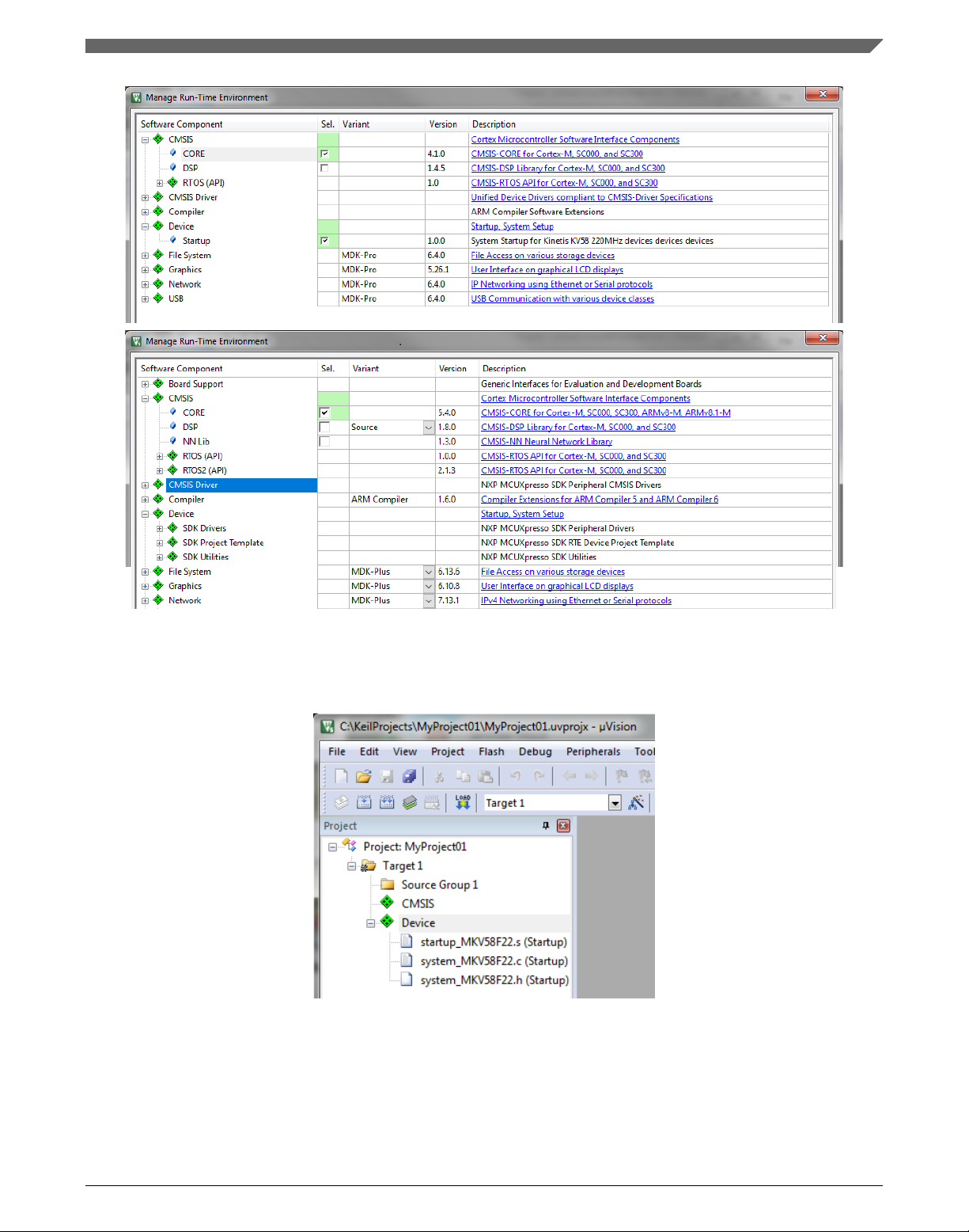
8. In the next dialog, expand the Device node, and tick the box next to the Startup node.
See Figure 1-17.
9. Expand the CMSIS node, and tick the box next to the CORE node.
GDFLIB User's Guide, Rev. 4, 12/2020
18 NXP Semiconductors
Page 19
Chapter 1 Library
Figure 1-17. Manage Run-Time Environment dialog
10. Click OK, and a new project is created. The new project is now visible in the lefthand part of Keil µVision. See Figure 1-18.
Figure 1-18. Project
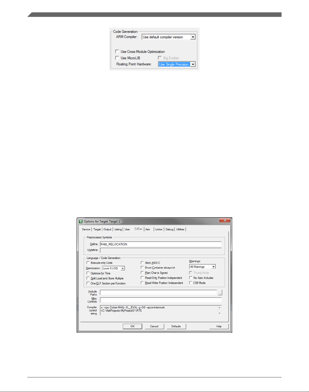
11. In the main menu, go to Project > Options for Target 'Target1'…, and a dialog
appears.
12. Select the Target tab.
13. Select Use Single Precision in the Floating Point Hardware option. See Figure 1-18.
GDFLIB User's Guide, Rev. 4, 12/2020
NXP Semiconductors 19
Page 20
Library integration into project (Keil µVision)
Figure 1-19. FPU
1.3.3 High-speed functions execution support
Some RT (or other) platforms contain high-speed functions execution support by
relocating all functions from the default Flash memory location to the RAM location for
much faster code access. The feature is important especially for devices with a slow Flash
interface. This section shows how to turn the RAM optimization feature support on and
off.
1. In the main menu, go to Project > Options for Target 'Target1'…, and a dialog
appears.
2. Select the C/C++ tab. See .
3. In the Include Preprocessor Symbols text box, type the following:
• RAM_RELOCATION — to turn the RAM optimization feature support on
If the define is defined, all RTCEL functions are put to the RAM.
Figure 1-20. Preprocessor symbols
4. Click OK in the main dialog.
GDFLIB User's Guide, Rev. 4, 12/2020
20 NXP Semiconductors
Page 21
Chapter 1 Library
The device reference manual shows how the__attribute__ ((section ("ram"))) atribute
works in connection with your device.
1.3.4 Linking the files into the project
GDFLIB requires MLIB to be included too. The following steps show how to include all
dependent modules.
To include the library files in the project, create groups and add them.
1. Right-click the Target 1 node in the left-hand part of the Project tree, and select Add
Group… from the menu. A new group with the name New Group is added.
2. Click the newly created group, and press F2 to rename it to RTCESL.
3. Right-click the RTCESL node, and select Add Existing Files to Group 'RTCESL'…
from the menu.
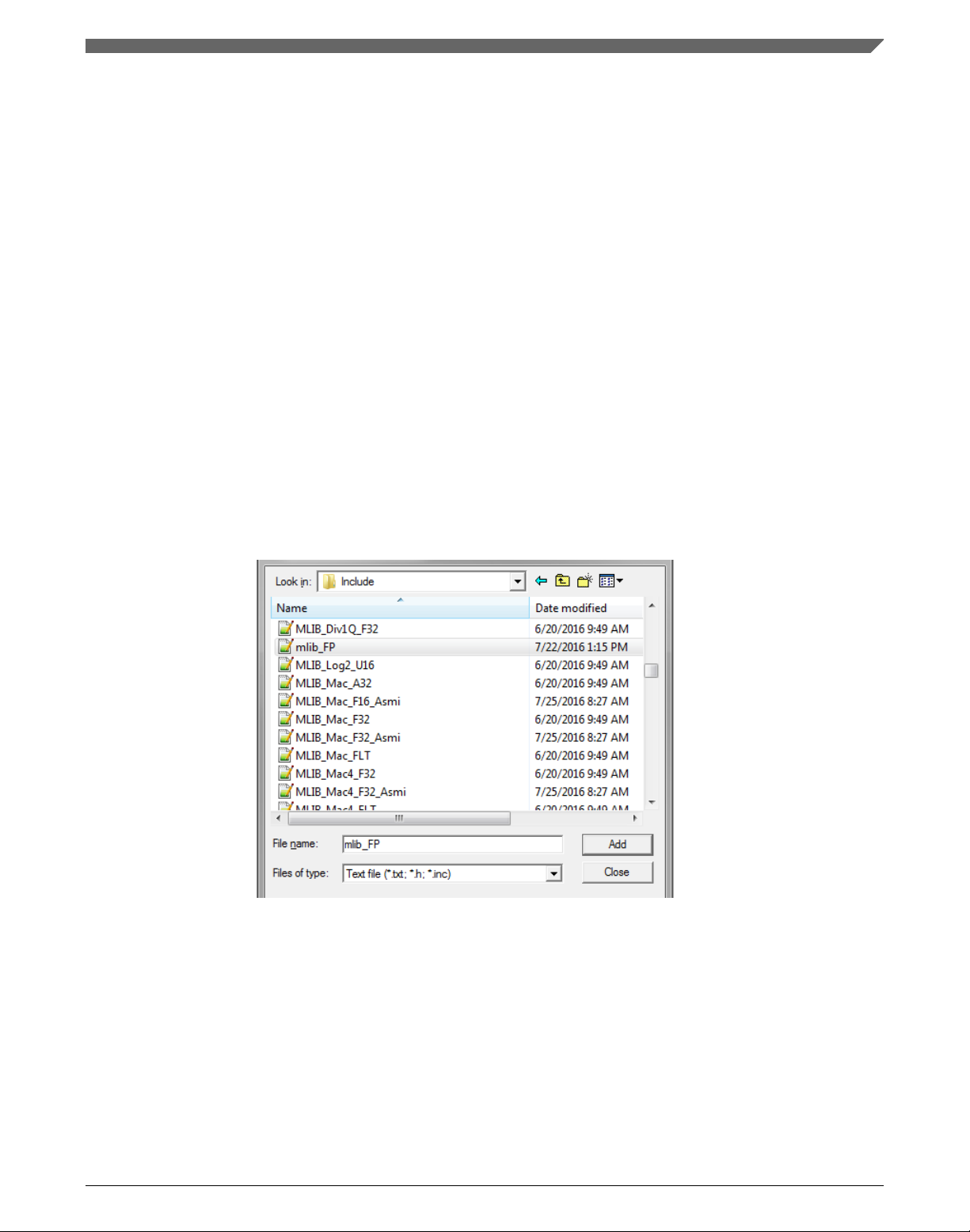
4. Navigate into the library installation folder C:\NXP\RTCESL
\CM7F_RTCESL_4.6_KEIL\MLIB\Include, and select the mlib_FP.h file. If the file
does not appear, set the Files of type filter to Text file. Click Add. See Figure 1-21.
Figure 1-21. Adding .h files dialog
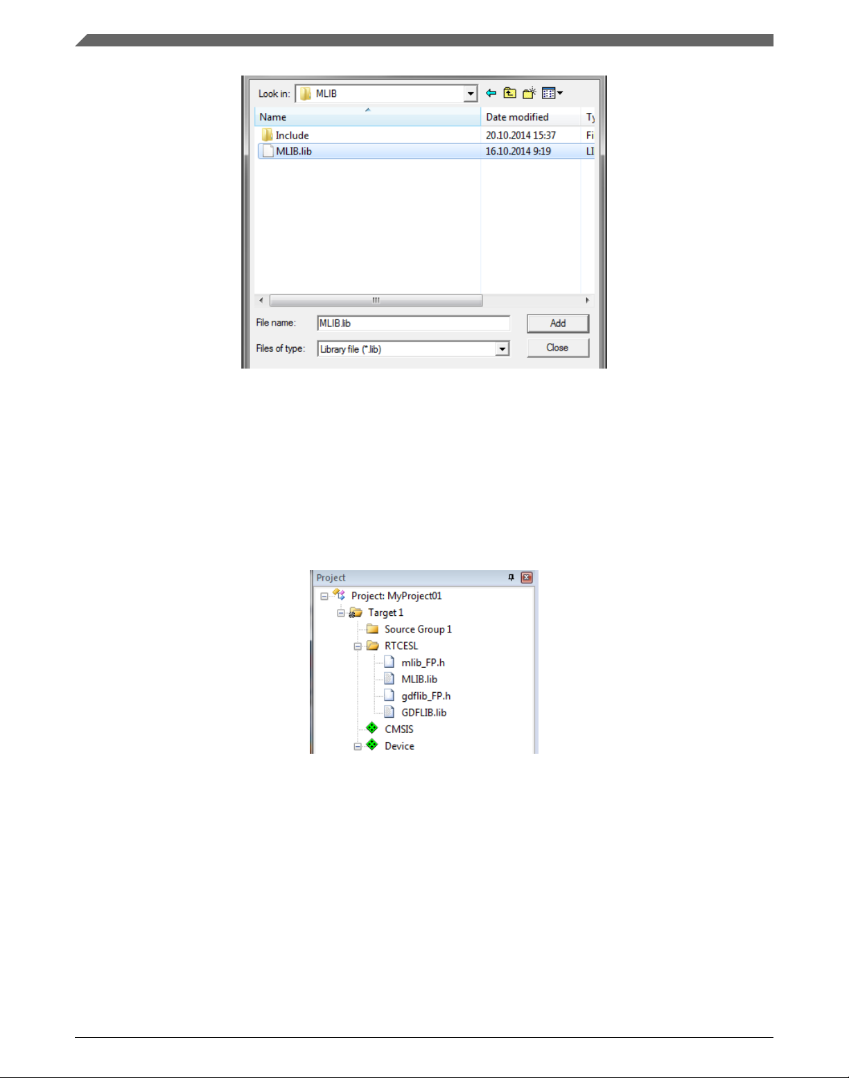
5. Navigate to the parent folder C:\NXP\RTCESL\CM7F_RTCESL_4.6_KEIL\MLIB,
and select the mlib.lib file. If the file does not appear, set the Files of type filter to
Library file. Click Add. See Figure 1-22.
GDFLIB User's Guide, Rev. 4, 12/2020
NXP Semiconductors 21
Page 22
Library integration into project (Keil µVision)
Figure 1-22. Adding .lib files dialog
6. Navigate into the library installation folder C:\NXP\RTCESL
\CM7F_RTCESL_4.6_KEIL\GDFLIB\Include, and select the gdflib_FP.h file. If the
file does not appear, set the Files of type filter to Text file. Click Add.
7. Navigate to the parent folder C:\NXP\RTCESL\CM7F_RTCESL_4.6_KEIL
\GDFLIB, and select the gdflib.lib file. If the file does not appear, set the Files of
type filter to Library file. Click Add.
8. Now, all necessary files are in the project tree; see Figure 1-23. Click Close.
Figure 1-23. Project workspace
1.3.5
Library path setup
The following steps show the inclusion of all dependent modules.
1. In the main menu, go to Project > Options for Target 'Target1'…, and a dialog
appears.
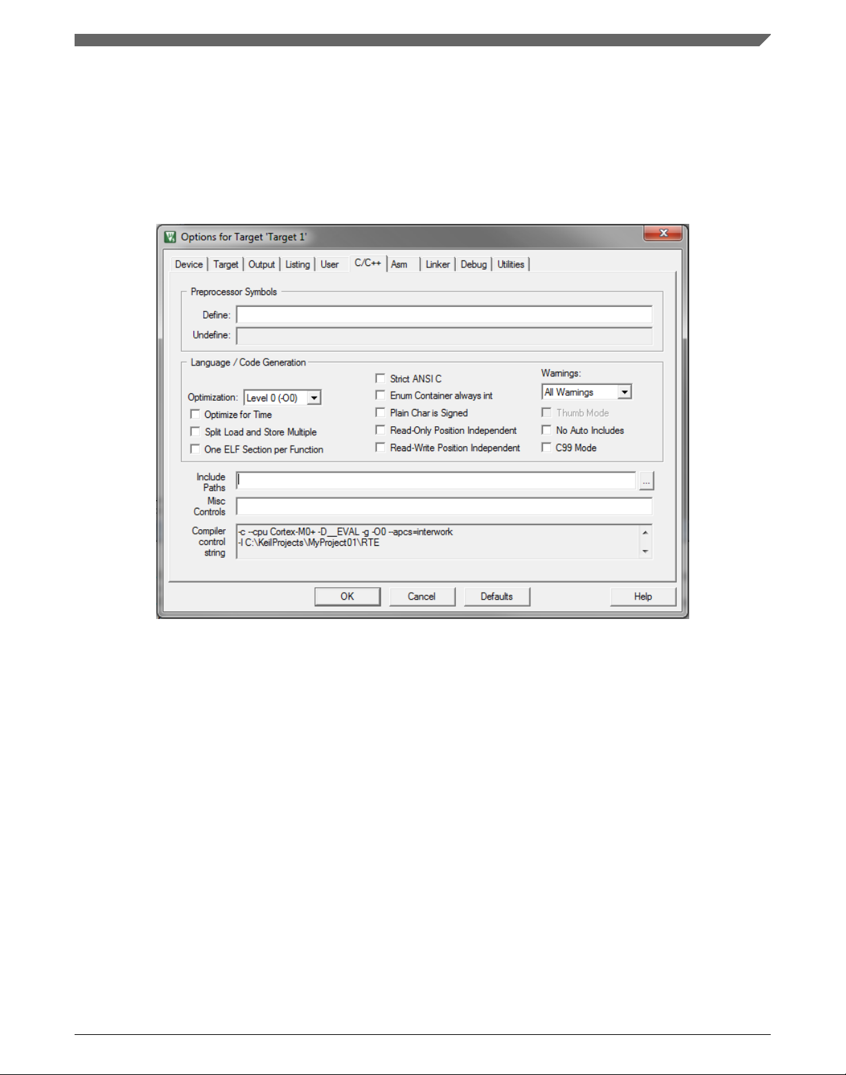
2. Select the C/C++ tab. See Figure 1-24.
GDFLIB User's Guide, Rev. 4, 12/2020
22 NXP Semiconductors
Page 23
Chapter 1 Library
3. In the Include Paths text box, type the following paths (if there are more paths, they
must be separated by ';') or add them by clicking the … button next to the text box:
• "C:\NXP\RTCESL\CM7F_RTCESL_4.6_KEIL\MLIB\Include"
• "C:\NXP\RTCESL\CM7F_RTCESL_4.6_KEIL\GDFLIB\Include"
4. Click OK.
5. Click OK in the main dialog.
Figure 1-24. Library path addition
Type the #include syntax into the code. Include the library into a source file. In the new
project, it is necessary to create a source file:
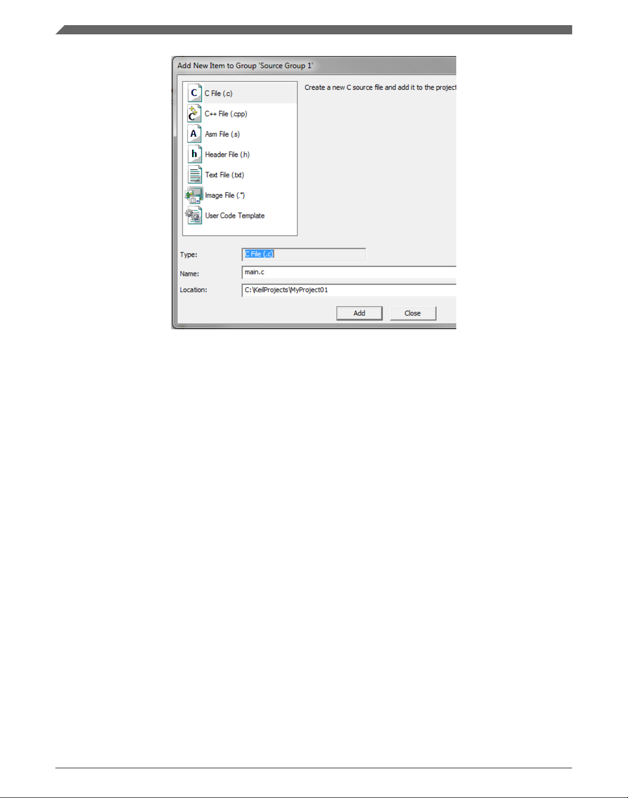
1. Right-click the Source Group 1 node, and Add New Item to Group 'Source Group
1'… from the menu.
2.
Select the C File (.c) option, and type a name of the file into the Name box, for
example 'main.c'. See Figure 1-25.
GDFLIB User's Guide, Rev. 4, 12/2020
NXP Semiconductors 23
Page 24
Library integration into project (IAR Embedded Workbench)
Figure 1-25. Adding new source file dialog
3. Click Add, and a new source file is created and opened up.
4. In the opened source file, include the following lines into the #include section, and
create a main function:
#include "mlib_FP.h"
#include "gdflib_FP.h"
int main(void)
{
while(1);
}
When you click the Build (F7) icon, the project will be compiled without errors.
1.4
Library integration into project (IAR Embedded
Workbench)
This section provides a step-by-step guide on how to quickly and easily include the
GDFLIB into an empty project or any MCUXpresso SDK example or demo application
projects using IAR Embedded Workbench. This example uses the default installation
path (C:\NXP\RTCESL\CM7F_RTCESL_4.6_IAR). If you have a different installation
path, use that path instead. If any MCUXpresso SDK project is intended to use (for
example hello_world project) go to Linking the files into the project chapter otherwise
read next chapter.
GDFLIB User's Guide, Rev. 4, 12/2020
24 NXP Semiconductors
Page 25

Chapter 1 Library
1.4.1 New project (without MCUXpresso SDK)
This example uses the NXP MKV58F1M0xxx22 part, and the default installation path
(C:\NXP\RTCESL\CM7F_RTCESL_4.6_IAR) is supposed. To start working on an
application, create a new project. If the project already exists and is opened, skip to the
next section. Perform these steps to create a new project:
1. Launch IAR Embedded Workbench.
2. In the main menu, select Project > Create New Project… so that the "Create New
Project" dialog appears. See Figure 1-26.
Figure 1-26. Create New Project dialog
3. Expand the C node in the tree, and select the "main" node. Click OK.
4. Navigate to the folder where you want to create the project, for example, C:
\IARProjects\MyProject01. Type the name of the project, for example, MyProject01.
Click Save, and a new project is created. The new project is now visible in the lefthand part of IAR Embedded Workbench. See Figure 1-27.
GDFLIB User's Guide, Rev. 4, 12/2020
NXP Semiconductors 25
Page 26

Library integration into project (IAR Embedded Workbench)
Figure 1-27. New project
5. In the main menu, go to Project > Options…, and a dialog appears.
6. In the Target tab, select the Device option, and click the button next to the dialog to
select the MCU. In this example, select NXP > KV5x > NXP MKV58F1M0xxx22.
Select VFPv5 single precision in the FPU option. Click OK. See Figure 1-28.
Figure 1-28. Options dialog
GDFLIB User's Guide, Rev. 4, 12/2020
26 NXP Semiconductors
Page 27

Chapter 1 Library
1.4.2 High-speed functions execution suppport
Some RT (or other) platforms contain high-speed functions execution support by
relocating all functions from the default Flash memory location to the RAM location for
much faster code access. The feature is important especially for devices with a slow Flash
interface. This section shows how to turn the RAM optimization feature support on and
off.
1. In the main menu, go to Project > Options…, and a dialog appears.
2. In the left-hand side column, select C/C++ Compiler.
3. In the right-hand side of the dialog, click the Preprocessor tab (it can be hidden on
the right; use the arrow icons for navigation).
4. In the text box (in Defined symbols: (one per line)), type the following (See Figure
1-29):
• RAM_RELOCATION — to turn the RAM optimization feature support on
If the define is defined, all RTCEL functions are put to the RAM.
Figure 1-29. Defined symbols
5. Click OK in the main dialog.
The device reference manual shows how the __ramfunc atribute works in connection with
your device.
GDFLIB User's Guide, Rev. 4, 12/2020
NXP Semiconductors 27
Page 28

Library integration into project (IAR Embedded Workbench)
1.4.3 Library path variable
To make the library integration easier, create a variable that will hold the information
about the library path.
1. In the main menu, go to Tools > Configure Custom Argument Variables…, and a
dialog appears.
2. Click the New Group button, and another dialog appears. In this dialog, type the
name of the group PATH, and click OK. See Figure 1-30.
Figure 1-30. New Group
3. Click on the newly created group, and click the Add Variable button. A dialog
appears.
4. Type this name: RTCESL_LOC
5. To set up the value, look for the library by clicking the '…' button, or just type the
installation path into the box: C:\NXP\RTCESL\CM7F_RTCESL_4.6_IAR. Click
OK.
6. In the main dialog, click OK. See Figure 1-31.
Figure 1-31. New variable
GDFLIB User's Guide, Rev. 4, 12/2020
28 NXP Semiconductors
Page 29

Chapter 1 Library
1.4.4 Linking the files into the project
GDFLIB requires MLIB to be included too. The following steps show the inclusion of all
dependent modules.
To include the library files into the project, create groups and add them.
1. Go to the main menu Project > Add Group…
2. Type RTCESL, and click OK.
3. Click on the newly created node RTCESL, go to Project > Add Group…, and create
a MLIB subgroup.
4. Click on the newly created node MLIB, and go to the main menu Project > Add
Files… See Figure 1-33.
5. Navigate into the library installation folder C:\NXP\RTCESL
\CM7F_RTCESL_4.6_IAR\MLIB\Include, and select the mlib_FP.h file. (If the file
does not appear, set the file-type filter to Source Files.) Click Open. See Figure 1-32.
6. Navigate into the library installation folder C:\NXP\RTCESL
\CM7F_RTCESL_4.6_IAR\MLIB, and select the mlib.a file. If the file does not
appear, set the file-type filter to Library / Object files. Click Open.
Figure 1-32. Add Files dialog
7. Click on the RTCESL node, go to Project > Add Group…, and create a GDFLIB
subgroup.
8. Click on the newly created node GDFLIB, and go to the main menu Project > Add
Files….
9. Navigate into the library installation folder C:\NXP\RTCESL
\CM7F_RTCESL_4.6_IAR\GDFLIB\Include, and select the gdflib_FP.h file. (If the
file does not appear, set the file-type filter to Source Files.) Click Open.
10. Navigate into the library installation folder C:\NXP\RTCESL
\CM7F_RTCESL_4.6_IAR\GDFLIB, and select the gdflib.a file. If the file does not
appear, set the file-type filter to Library / Object files. Click Open.
11. Now you will see the files added in the workspace. See Figure 1-33.
GDFLIB User's Guide, Rev. 4, 12/2020
NXP Semiconductors 29
Page 30

Library integration into project (IAR Embedded Workbench)
Figure 1-33. Project workspace
1.4.5
Library path setup
The following steps show the inclusion of all dependent modules:
1. In the main menu, go to Project > Options…, and a dialog appears.
2. In the left-hand column, select C/C++ Compiler.
3. In the right-hand part of the dialog, click on the Preprocessor tab (it can be hidden in
the right; use the arrow icons for navigation).
4. In the text box (at the Additional include directories title), type the following folder
(using the created variable):
• $RTCESL_LOC$\MLIB\Include
• $RTCESL_LOC$\GDFLIB\Include
5. Click OK in the main dialog. See Figure 1-34.
GDFLIB User's Guide, Rev. 4, 12/2020
30 NXP Semiconductors
Page 31

Chapter 1 Library
Figure 1-34. Library path adition
Type the #include syntax into the code. Include the library included into the main.c file.
In the workspace tree, double-click the main.c file. After the main.c file opens up, include
the following lines into the #include section:
#include "mlib_FP.h"
#include "gdflib_FP.h"
When you click the Make icon, the project will be compiled without errors.
GDFLIB User's Guide, Rev. 4, 12/2020
NXP Semiconductors 31
Page 32

Library integration into project (IAR Embedded Workbench)
GDFLIB User's Guide, Rev. 4, 12/2020
32 NXP Semiconductors
Page 33

Chapter 2
Algorithms in detail
2.1 GDFLIB_FilterExp
The
GDFLIB_FilterExp function calculates the exponential smoothing. The exponential
filter is the simplest filter with only one tuning parameter, requiring to store only one
variable - the filter output (it is used in the next step). For a proper use, it is recommended
that the algorithm is initialized by the GDFLIB_FilterExpInit function, before using the
GDFLIB_FilterExp function.
The filter calculation consists of the following equation:
Equation 1.
where:
• x(k) is the actual value of the input signal
• y(k) is the actual filter output
• A is the filter constant (0 ; 1) (it defines the smoothness of the exponential filter)
The exponential filter tuning is based on these rules: for a small value of the filter
constant there is a strong filtering effect (if A = 0 then the output equals the new input).
For a high value of the filtering constant, there is a weak filtering effect (if A = 1 then the
new input is ignored). The filter constant defines the ratio between the filter inputs and
the last step output, used for the next calculation.
2.1.1
This function is available in the following versions:
NXP Semiconductors 33
Available versions
GDFLIB User's Guide, Rev. 4, 12/2020
Page 34

GDFLIB_FilterExp
• Fractional output - the output is the fractional portion of the result; the result is
within the range <-1 ; 1). The parameter uses the fraction type.
• Floating-point output - the output is the floating-point result within the type's full
range. The parameter is of a floating-point range as well.
The available versions of the GDFLIB_FilterExpInit function are shown in the following
table:
Table 2-1. Init function versions
Function name Input
type
GDFLIB_FilterExpInit_F16 frac16_t GDFLIB_FILTER_EXP_T_F32 * void The input argument is a 16-bit
GDFLIB_FilterExpInit_FLT float_t GDFLIB_FILTER_EXP_T_FLT * void The input argument is a 32-bit single
Parameters Result
type
Description
fractional value that represents the
initial value of the filter at the current
step. The input is within the range
<-1 ; 1). The parameters' structure is
pointed to by a pointer.
precision floating-point value that
represents the initial value of the filter
at the current step. The input is within
the full range. The parameters'
structure is pointed to by a pointer.
The available versions of the GDFLIB_FilterExp function are shown in the following
table:
Table 2-2. Function versions
Function name Input
type
GDFLIB_FilterExp_F16 frac16_t GDFLIB_FILTER_EXP_T_F32 * frac16_t The input argument is a 16-bit fractional
GDFLIB_FilterExp_FLT float_t GDFLIB_FILTER_EXP_T_FLT * float_t The input argument is a 32-bit single
Parameters Result
type
Description
value of the input signal to be filtered within
the range <-1 ; 1). The parameters'
structure is pointed to by a pointer. The
function returns a 16-bit fractional value
within the range <-1 ; 1).
precision floating-point value of the input
signal to be filtered within the full range.
The parameters' structure is pointed to by a
pointer. The function returns a 32-bit single
precision floating-point value within the full
range.
GDFLIB User's Guide, Rev. 4, 12/2020
34 NXP Semiconductors
Page 35

2.1.2 GDFLIB_FILTER_EXP_T_F32
Chapter 2 Algorithms in detail
Variable
name
f32A frac32_t Filter constant value (filter parameter). It defines the smoothness of the exponential filter (high value
f32AccK_1 frac32_t Filter accumulator (last step output) value. The parameter is a 32-bit accumulator type within the
Input
type
Description
= small filtering effect, low value = strong filtering effect). It is usually defined as:
Where Ts is the sample time and τ is the filter time constant. The parameter is a 32-bit fractional
value within the range <-0 ; 1). Set by the user.
range <-1.0 ; 1.0). Controlled by the algorithm.
2.1.3 GDFLIB_FILTER_EXP_T_FLT
Variable
name
fltA float_t Filter constant value (filter parameter). It defines the smoothness of the exponential filter (high value
Input
type
Description
= small filtering effect, low value = strong filtering effect). It is ussually defined as:
Where Ts is the sample time and τ is the filter time constant. The parameter is a 32-bit single
precision floating-point type within the range (0 ; 1.0>. Set by the user.
fltAccK_1 float_t Filter accumulator (last step output) value. The parameter is a 32-bit accumulator type within the 32-
bit single precision floating-point range. Controlled by the algorithm.
2.1.4 Declaration
The available GDFLIB_FilterExpInit functions have the following declarations:
void GDFLIB_FilterExpInit_F16(frac16_t f16InitVal, GDFLIB_FILTER_EXP_T_F32 *psParam)
void GDFLIB_FilterExpInit_FLT(float_t fltInitVal, GDFLIB_FILTER_EXP_T_FLT *psParam)
The available GDFLIB_FilterExp functions have the following declarations:
frac16_t GDFLIB_FilterExp_F16(frac16_t f16InX, GDFLIB_FILTER_EXP_T_F32 *psParam)
float_t GDFLIB_FilterExp_FLT(float_t fltInX, GDFLIB_FILTER_EXP_T_FLT *psParam)
GDFLIB User's Guide, Rev. 4, 12/2020
NXP Semiconductors 35
Page 36

GDFLIB_FilterExp
2.1.5 Function use
The use of the GDFLIB_FilterExpInit and GDFLIB_FilterExp functions is shown in the
following examples:
Fixed-point version:
#include "gdflib.h"
static frac16_t f16Result;
static frac16_t f16InitVal, f16InX;
static GDFLIB_FILTER_EXP_T_F32 sFilterParam;
void Isr(void);
void main(void)
{
f16InitVal = FRAC16(0.0); /* f16InitVal = 0.0 */
/* Filter constant = 0.05 */
sFilterParam.f32A = FRAC32(0.05);
GDFLIB_FilterExpInit_F16(f16InitVal, &sFilterParam);
f16InX = FRAC16(0.5);
}
/* periodically called function */
void Isr(void)
{
f16Result = GDFLIB_FilterExp_F16(f16InX, &sFilterParam);
}
Floating-point version:
#include "gdflib.h"
static float_t fltResult;
static float_t fltInitVal, fltInX;
static GDFLIB_FILTER_EXP_T_FLT sFilterParam;
void Isr(void);
void main(void)
{
fltInitVal = 0.0F; /* fltInitVal = 0.0 */
/* Filter constant = 0.05 */
sFilterParam.fltA = 0.05F;
GDFLIB_FilterExpInit_FLT(fltInitVal, &sFilterParam);
fltInX = 0.5F;
}
/* periodically called function */
void Isr(void)
{
fltResult = GDFLIB_FilterExp_FLT(fltInX, &sFilterParam);
}
GDFLIB User's Guide, Rev. 4, 12/2020
36 NXP Semiconductors
Page 37

Chapter 2 Algorithms in detail
2.2 GDFLIB_FilterIIR1
This function calculates the first-order direct form 1 IIR filter.
For a proper use, it is recommended that the algorithm is initialized by the
GDFLIB_FilterIIR1Init function, before using the GDFLIB_FilterIIR1 function. The
GDFLIB_FilterIIR1Init function initializes the buffer and coefficients of the first-order
IIR filter.
The GDFLIB_FilterIIR1 function calculates the first-order infinite impulse response
(IIR) filter. The IIR filters are also called recursive filters, because both the input and the
previously calculated output values are used for calculation. This form of feedback
enables the transfer of energy from the output to the input, which leads to an infinitely
long impulse response (IIR). A general form of the IIR filter, expressed as a transfer
function in the Z-domain, is described as follows:
Equation 2.
where N denotes the filter order. The first-order IIR filter in the Z-domain is expressed as
follows:
Equation 3.
which is transformed into a time-domain difference equation as follows:
Equation 4.
The filter difference equation is implemented in the digital signal controller directly, as
given in Equation 4 on page 37; this equation represents a direct-form 1 first-order IIR
filter, as shown in Figure 2-1.
Figure 2-1. Direct form 1 first-order IIR filter
GDFLIB User's Guide, Rev. 4, 12/2020
NXP Semiconductors 37
Page 38

GDFLIB_FilterIIR1
The coefficients of the filter shown in Figure 2-1 can be designed to meet the
requirements for the first-order low-pass filter (LPF) or high-pass filter (HPF). The
coefficient quantization error is not important in the case of a first-order filter due to a
finite precision arithmetic. A higher-order LPF or HPF can be obtained by connecting a
number of first-order filters in series. The number of connections gives the order of the
resulting filter.
The filter coefficients must be defined before calling this function. As some coefficients
can be greater than 1 (and lesser than 2), the coefficients are scaled down (divided) by 2.0
for the fractional version of the algorithm. For faster calculation, the A coefficient is signinverted. The function returns the filtered value of the input in the step k, and stores the
input and the output values in the step k into the filter buffer.
2.2.1
Available versions
This function is available in the following versions:
• Fractional output - the output is the fractional portion of the result; the result is
within the range <-1 ; 1).
• Floating-point output - the output is a floating-point result within the type's full
range.
The available versions of the GDFLIB_FilterIIR1Init function are shown in the following
table:
Table 2-3. Init function versions
Function name Parameters Result
type
GDFLIB_FilterIIR1Init_F16 GDFLIB_FILTER_IIR1_T_F32 * void Filter initialization (reset) function. The
parameters' structure is pointed to by a
pointer.
GDFLIB_FilterIIR1Init_FLT GDFLIB_FILTER_IIR1_T_FLT * void Filter initialization (reset) function. The
parameters' structure is pointed to by a
pointer.
Description
GDFLIB User's Guide, Rev. 4, 12/2020
38 NXP Semiconductors
Page 39

Chapter 2 Algorithms in detail
The available versions of the GDFLIB_FilterIIR1 function are shown in the following
table:
Table 2-4. Function versions
Function name Input
type
GDFLIB_FilterIIR1_F16 frac16_t GDFLIB_FILTER_IIR1_T_F32 * frac16_t The input argument is a 16-bit
GDFLIB_FilterIIR1_FLT float_t GDFLIB_FILTER_IIR1_T_FLT * float_t The input argument is a 32-bit single
Parameters Result
type
Description
fractional value of the input signal to
be filtered within the range <-1 ; 1).
The parameters' structure is pointed
to by a pointer. The function returns
a 16-bit fractional value within the
range <-1 ; 1).
precision floating-point value of the
input signal within the full range. The
parameters' structure is pointed to
by a pointer. The function returns a
32-bit single precision floating-point
value within the full range.
2.2.2 GDFLIB_FILTER_IIR1_T_F32
Variable name Input type Description
sFltCoeff GDFLIB_FILTER_IIR1_COEFF_T_F32 * Substructure containing filter coefficients.
f32FltBfrY[1] frac32_t Internal buffer of y-history. Controlled by the
algorithm.
f16FltBfrX[1] frac16_t Internal buffer of x-history. Controlled by the
algorithm.
2.2.3 GDFLIB_FILTER_IIR1_COEFF_T_F32
Variable name Type Description
f32B0 frac32_t B0 coefficient of the IIR1 filter. Set by the user, and must be divided by 2.
f32B1 frac32_t B1 coefficient of the IIR1 filter. Set by the user, and must be divided by 2.
f32A1 frac32_t A1 (sign-inverted) coefficient of the IIR1 filter. Set by the user, and must be divided by -2
(negative two).
GDFLIB User's Guide, Rev. 4, 12/2020
NXP Semiconductors 39
Page 40

GDFLIB_FilterIIR1
2.2.4 GDFLIB_FILTER_IIR1_T_FLT
Variable name Input type Description
sFltCoeff GDFLIB_FILTER_IIR1_COEFF_T_FLT * Substructure containing filter coefficients.
fltFltBfrY[1] float_t Internal buffer of y-history. Controlled by the
algorithm.
fltFltBfrX[1] float_t Internal buffer of x-history. Controlled by the
algorithm.
2.2.5 GDFLIB_FILTER_IIR1_COEFF_T_FLT
Variable name Type Description
fltB0 float_t B0 coefficient of the IIR1 filter. Set by the user.
fltB1 float_t B1 coefficient of the IIR1 filter. Set by the user.
fltA1 float_t A1 (sign-inverted) coefficient of the IIR1 filter. Set by the user.
2.2.6 Declaration
The available GDFLIB_FilterIIR1Init functions have the following declarations:
void GDFLIB_FilterIIR1Init_F16(GDFLIB_FILTER_IIR1_T_F32 *psParam)
void GDFLIB_FilterIIR1Init_FLT(GDFLIB_FILTER_IIR1_T_FLT *psParam)
The available GDFLIB_FilterIIR1 functions have the following declarations:
frac16_t GDFLIB_FilterIIR1_F16(frac16_t f16InX, GDFLIB_FILTER_IIR1_T_F32 *psParam)
float_t GDFLIB_FilterIIR1_FLT(float_t fltInX, GDFLIB_FILTER_IIR1_T_FLT *psParam)
2.2.7
There are plenty of methods for calculating the coefficients. The following example
shows the use of Matlab to set up a low-pass filter with the 500 Hz sampling frequency,
and 240 Hz stopped frequency with a 20 dB attenutation. Maximum passband ripple is 3
dB at the cut-off frequency of 50 Hz.
% sampling frequency 500 Hz, low pass
Ts = 1 / 500
Calculation of filter coefficients
% cut-off frequency 50 Hz
Fc = 50
GDFLIB User's Guide, Rev. 4, 12/2020
40 NXP Semiconductors
Page 41

% max. passband ripple 3 dB
Rp = 3
% stopped frequency 240Hz
Fs = 240
% attenuation 20 dB
Rs = 20
% checking order of the filter
n = buttord(2 * Ts * Fc, 2 * Ts * Fs, Rp, Rs)
% n = 1, i.e. the filter is achievable with the 1st order
% getting the filter coefficients
[b, a] = butter(n, 2 * Ts * Fc, 'low');
% the coefs are:
% b0 = 0.245237275252786, b1 = 0.245237275252786
% a0 = 1.0000, a1 = -0.509525449494429
The filter response is shown in Figure 2-2.
Chapter 2 Algorithms in detail
Figure 2-2. Filter response
2.2.8
Function use
The use of the GDFLIB_FilterIIR1Init and GDFLIB_FilterIIR1 functions is shown in the
following examples. The filter uses the above-calculated coefficients:
Fixed-point version:
GDFLIB User's Guide, Rev. 4, 12/2020
NXP Semiconductors 41
Page 42

GDFLIB_FilterIIR2
#include "gdflib.h"
static frac16_t f16Result;
static frac16_t f16InX;
static GDFLIB_FILTER_IIR1_T_F32 sFilterParam;
void Isr(void);
void main(void)
{
sFilterParam.sFltCoeff.f32B0 = FRAC32(0.245237275252786 / 2.0);
sFilterParam.sFltCoeff.f32B1 = FRAC32(0.245237275252786 / 2.0);
sFilterParam.sFltCoeff.f32A1 = FRAC32(-0.509525449494429 / -2.0);
GDFLIB_FilterIIR1Init_F16(&sFilterParam);
f16InX = FRAC16(0.1);
}
/* periodically called function */
void Isr(void)
{
f16Result = GDFLIB_FilterIIR1_F16(f16InX, &sFilterParam);
}
Floating-point version:
#include "gdflib.h"
static float_t fltResult;
static float_t fltInX;
static GDFLIB_FILTER_IIR1_T_FLT sFilterParam;
void Isr(void);
void main(void)
{
sFilterParam.sFltCoeff.fltB0 = 0.245237275252786f;
sFilterParam.sFltCoeff.fltB1 = 0.245237275252786f;
sFilterParam.sFltCoeff.fltA1 = -0.509525449494429f;
GDFLIB_FilterIIR1Init_FLT(&sFilterParam);
fltInX = 0.1F;
}
/* periodically called function */
void Isr(void)
{
fltResult = GDFLIB_FilterIIR1_FLT(fltInX, &sFilterParam);
}
2.3
GDFLIB_FilterIIR2
This function calculates the second-order direct-form 1 IIR filter.
GDFLIB User's Guide, Rev. 4, 12/2020
42 NXP Semiconductors
Page 43

Chapter 2 Algorithms in detail
For a proper use, it is recommended that the algorithm is initialized by the
GDFLIB_FilterIIR2Init function, before using the GDFLIB_FilterIIR2 function. The
GDFLIB_FilterIIR2Init function initializes the buffer and coefficients of the secondorder IIR filter.
The GDFLIB_FilterIIR2 function calculates the second-order infinite impulse response
(IIR) filter. The IIR filters are also called recursive filters, because both the input and the
previously calculated output values are used for calculation. This form of feedback
enables the transfer of energy from the output to the input, which leads to an infinitely
long impulse response (IIR). A general form of the IIR filter, expressed as a transfer
function in the Z-domain, is described as follows:
Equation 5.
where N denotes the filter order. The second-order IIR filter in the Z-domain is expressed
as follows:
Equation 6.
which is transformed into a time-domain difference equation as follows:
Equation 7.
The filter difference equation is implemented in the digital signal controller directly, as
given in Equation 7 on page 43; this equation represents a direct-form 1 second-order IIR
filter, as depicted in Figure 2-3.
Figure 2-3. Direct-form 1 second-order IIR filter
GDFLIB User's Guide, Rev. 4, 12/2020
NXP Semiconductors 43
Page 44

GDFLIB_FilterIIR2
The coefficients of the filter depicted in Figure 2-3 can be designed to meet the
requirements for the second-order low-pass filter (LPF), high-pass filter (HPF), band-pass
filter (BPF) or band-stop filter (BSF). The coefficient quantization error can be neglected
in the case of a second-order filter due to a finite precision arithmetic. A higher-order
LPF or HPF can be obtained by connecting a number of second-order filters in series.
The number of connections gives the order of the resulting filter.
The filter coefficients must be defined before calling this function. As some coefficients
can be greater than 1 (and lesser than 2), the coefficients are scaled down (divided) by 2.0
for the fractional version of the algorithm. For faster calculation, the A coefficients are
sign-inverted. The function returns the filtered value of the input in the step k, and stores
the input and output values in the step k into the filter buffer.
2.3.1
Available versions
This function is available in the following versions:
• Fractional output - the output is the fractional portion of the result; the result is
within the range <-1 ; 1).
• Floating-point output - the output is the floating-point result within the type's full
range.
The available versions of the GDFLIB_FilterIIR2Init function are shown in the following
table:
Table 2-5. Init function versions
Function name Parameters Result
type
GDFLIB_FilterIIR2Init_F16 GDFLIB_FILTER_IIR2_T_F32 * void Filter initialization (reset) function. The
parameters' structure is pointed to by a
pointer.
GDFLIB_FilterIIR2Init_FLT GDFLIB_FILTER_IIR2_T_FLT * void Filter initialization (reset) function. The
parameters' structure is pointed to by a
pointer.
Description
GDFLIB User's Guide, Rev. 4, 12/2020
44 NXP Semiconductors
Page 45

Chapter 2 Algorithms in detail
The available versions of the GDFLIB_FilterIIR2 function are shown in the following
table:
Table 2-6. Function versions
Function name Input
type
GDFLIB_FilterIIR2_F16 frac16_t GDFLIB_FILTER_IIR2_T_F32 * frac16_t Input argument is a 16-bit fractional
GDFLIB_FilterIIR2_FLT float_t GDFLIB_FILTER_IIR2_T_FLT * float_t Input argument is a 32-bit single
Parameters Result
type
Description
value of the input signal to be filtered
within the range <-1 ; 1). The
parameters' structure is pointed to
by a pointer. The function returns a
16-bit fractional value within the
range <-1 ; 1).
precision floating-point value of the
input signal within the full range. The
parameters' structure is pointed to
by a pointer. The function returns a
32-bit single precision floating-point
value within the full range.
2.3.2 GDFLIB_FILTER_IIR2_T_F32
Variable name Input type Description
sFltCoeff GDFLIB_FILTER_IIR2_COEFF_T_F32 * Substructure containing filter coefficients.
f32FltBfrY[2] frac32_t Internal buffer of y-history. Controlled by the
algorithm.
f16FltBfrX[2] frac16_t Internal buffer of x-history. Controlled by the
algorithm.
2.3.3 GDFLIB_FILTER_IIR2_COEFF_T_F32
Variable name Type Description
f32B0 frac32_t B0 coefficient of the IIR2 filter. Set by the user, and must be divided by 2.
f32B1 frac32_t B1 coefficient of the IIR2 filter. Set by the user, and must be divided by 2.
f32B2 frac32_t B2 coefficient of the IIR2 filter. Set by the user, and must be divided by 2.
f32A1 frac32_t A1 (sign-inverted) coefficient of the IIR2 filter. Set by the user, and must be divided by -2
(negative two).
f32A2 frac32_t A2 (sign-inverted) coefficient of the IIR2 filter. Set by the user, and must be divided by -2
(negative two).
GDFLIB User's Guide, Rev. 4, 12/2020
NXP Semiconductors 45
Page 46

GDFLIB_FilterIIR2
2.3.4 GDFLIB_FILTER_IIR2_T_FLT
Variable name Input type Description
sFltCoeff GDFLIB_FILTER_IIR2_COEFF_T_FLT * Substructure containing filter coefficients.
fltFltBfrY[2] float_t Internal buffer of y-history. Controlled by the
algorithm.
fltFltBfrX[2] float_t Internal buffer of x-history. Controlled by the
algorithm.
2.3.5 GDFLIB_FILTER_IIR2_COEFF_T_FLT
Variable name Type Description
fltB0 float_t B0 coefficient of the IIR2 filter. Set by the user.
fltB1 float_t B1 coefficient of the IIR2 filter. Set by the user.
fltB2 float_t B2 coefficient of the IIR2 filter. Set by the user.
fltA1 float_t A1 (sign-inverted) coefficient of the IIR2 filter. Set by the user.
fltA2 float_t A2 (sign-inverted) coefficient of the IIR2 filter. Set by the user.
2.3.6 Declaration
The available GDFLIB_FilterIIR2Init functions have the following declarations:
void GDFLIB_FilterIIR2Init_F16(GDFLIB_FILTER_IIR2_T_F32 *psParam)
void GDFLIB_FilterIIR2Init_FLT(GDFLIB_FILTER_IIR2_T_FLT *psParam)
The available GDFLIB_FilterIIR2 functions have the following declarations:
frac16_t GDFLIB_FilterIIR2_F16(frac16_t f16InX, GDFLIB_FILTER_IIR2_T_F32 *psParam)
float_t GDFLIB_FilterIIR2_FLT(float_t fltInX, GDFLIB_FILTER_IIR2_T_FLT *psParam)
2.3.7
There are plenty of methods for calculating the coefficients. The following example
shows the use of Matlab to set up a stopband filter with the 1000 Hz sampling frequency,
100 Hz stop frequency with 10 dB attenuation, and 30 Hz bandwidth. Maximum
passband ripple is 3 dB.
Calculation of filter coefficients
GDFLIB User's Guide, Rev. 4, 12/2020
46 NXP Semiconductors
Page 47

Chapter 2 Algorithms in detail
% sampling frequency 1000 Hz, stop band
Ts = 1 / 1000
% center stop frequency 100 Hz
Fc = 50
% attenuation 10 dB
Rs = 10
% bandwidth 30 Hz
Fbw = 30
% max. passband ripple 3 dB
Rp = 3
% checking order of the filter
n = buttord(2 * Ts * [Fc - Fbw /2 Fc + Fbw / 2], 2 * Ts * [Fc - Fbw Fc + Fbw], Rp, Rs)
% n = 2, i.e. the filter is achievable with the 2nd order
% getting the filter coefficients
[b, a] = butter(n / 2, 2 * Ts * [Fc - Fbw /2 Fc + Fbw / 2], 'stop')
% the coefs are:
% b0 = 0.913635972986238, b1 = -1.745585863109291, b2 = 0.913635972986238
% a0 = 1.0000, a1 = -1.745585863109291, a2 = 0.827271945972476
The filter response is shown in Figure 2-4.
Figure 2-4. Filter response
2.3.8
Function use
The use of the GDFLIB_FilterIIR2Init and GDFLIB_FilterIIR2 functions is shown in the
following examples. The filter uses the above-calculated coefficients:
GDFLIB User's Guide, Rev. 4, 12/2020
NXP Semiconductors 47
Page 48

GDFLIB_FilterIIR2
Fixed-point version:
#include "gdflib.h"
static frac16_t f16Result;
static frac16_t f16InX;
static GDFLIB_FILTER_IIR2_T_F32 sFilterParam;
void Isr(void);
void main(void)
{
sFilterParam.sFltCoeff.f32B0 = FRAC32(0.913635972986238 / 2.0);
sFilterParam.sFltCoeff.f32B1 = FRAC32(-1.745585863109291 / 2.0);
sFilterParam.sFltCoeff.f32B2 = FRAC32(0.913635972986238 / 2.0);
sFilterParam.sFltCoeff.f32A1 = FRAC32(-1.745585863109291 / -2.0);
sFilterParam.sFltCoeff.f32A2 = FRAC32(0.827271945972476 / -2.0);
GDFLIB_FilterIIR2Init_F16(&sFilterParam);
f16InX = FRAC16(0.1);
}
/* periodically called function */
void Isr(void)
{
f16Result = GDFLIB_FilterIIR2_F16(f16InX, &sFilterParam);
}
Floating-point version:
#include "gdflib.h"
static float_t fltResult;
static float_t fltInX;
static GDFLIB_FILTER_IIR2_T_FLT sFilterParam;
void Isr(void);
void main(void)
{
sFilterParam.sFltCoeff.fltB0 = 0.913635972986238f;
sFilterParam.sFltCoeff.fltB1 = -1.745585863109291f;
sFilterParam.sFltCoeff.fltB2 = 0.913635972986238f;
sFilterParam.sFltCoeff.fltA1 = -1.745585863109291f;
sFilterParam.sFltCoeff.fltA2 = 0.827271945972476f;
GDFLIB_FilterIIR2Init_FLT(&sFilterParam);
fltInX = 0.1F;
}
/* periodically called function */
void Isr(void)
{
fltResult = GDFLIB_FilterIIR2_FLT(fltInX, &sFilterParam);
}
GDFLIB User's Guide, Rev. 4, 12/2020
48 NXP Semiconductors
Page 49

Chapter 2 Algorithms in detail
2.4 GDFLIB_FilterIIR3
This function calculates the third-order direct-form 1 IIR filter.
For a proper use, it is recommended to initialize the algorithm by the
GDFLIB_FilterIIR3Init function before using the GDFLIB_FilterIIR3 function. The
GDFLIB_FilterIIR3Init function initializes the buffer and coefficients of the third-order
IIR filter.
The GDFLIB_FilterIIR3 function calculates the third-order infinite impulse response
(IIR) filter. The IIR filters are also called recursive filters because both the input and the
previously calculated output values are used for calculation. This form of feedback
enables the transfer of energy from the output to the input, which leads to an infinitely
long impulse response (IIR). A general form of the IIR filter (expressed as a transfer
function in the Z-domain) is described as follows:
Equation 8.
where N denotes the filter order. The third-order IIR filter in the Z-domain is expressed
as follows:
Equation 9.
which is transformed into a time-domain difference equation as follows:
Equation 10.
The filter difference equation is implemented in the digital signal controller directly, as
given in Equation 10 on page 49. This equation represents a direct-form 1 third-order IIR
filter, as depicted in Figure 2-5.
GDFLIB User's Guide, Rev. 4, 12/2020
NXP Semiconductors 49
Page 50

GDFLIB_FilterIIR3
Figure 2-5. Direct-form 1 third-order IIR filter
The coefficients of the filter depicted in Figure 2-5 can be designed to meet the
requirements for the third-order low-pass filter (LPF) or high-pass filter (HPF). The
coefficient quantization error can be neglected in the case of a third-order filter due to a
finite precision arithmetic. A higher-order LPF or HPF can be obtained by connecting a
number of third-order filters in series. The number of connections gives the order of the
resulting filter.
Define the filter coefficients before calling this function. As some coefficients can be
greater than 1 (and lesser than 4), the coefficients are scaled down (divided) by 4.0 for the
fractional version of the algorithm. For a faster calculation, the A coefficients are signinverted. The function returns the filtered value of the input in the step k, and stores the
input and output values in the step k into the filter buffer.
2.4.1
Available versions
This function is available in the following versions:
• Fractional output - the output is the fractional portion of the result; the result is
within the range <-1 ; 1).
• Floating-point output - the output is the floating-point result within the type's full
range.
GDFLIB User's Guide, Rev. 4, 12/2020
50 NXP Semiconductors
Page 51

Chapter 2 Algorithms in detail
The available versions of the GDFLIB_FilterIIR3Init function are shown in the following
table:
Table 2-7. Init function versions
Function name Parameters Result
type
GDFLIB_FilterIIR3Init_F16 GDFLIB_FILTER_IIR3_T_F32 * void Filter initialization (reset) function. The
parameters' structure is pointed to by a
pointer.
GDFLIB_FilterIIR3Init_FLT GDFLIB_FILTER_IIR3_T_FLT * void Filter initialization (reset) function. The
parameters' structure is pointed to by a
pointer.
Description
The available versions of the GDFLIB_FilterIIR3 function are shown in the following
table:
Table 2-8. Function versions
Function name Input
type
GDFLIB_FilterIIR3_F16 frac16_t GDFLIB_FILTER_IIR3_T_F32 * frac16_t Input argument is a 16-bit fractional
GDFLIB_FilterIIR3_FLT float_t GDFLIB_FILTER_IIR3_T_FLT * float_t Input argument is a 32-bit single
Parameters Result
type
Description
value of the input signal to be filtered
within the range <-1 ; 1). The
parameters' structure is pointed to
by a pointer. The function returns a
16-bit fractional value within the
range <-1 ; 1).
precision floating-point value of the
input signal within the full range. The
parameters' structure is pointed to
by a pointer. The function returns a
32-bit single precision floating-point
value within the full range.
2.4.2 GDFLIB_FILTER_IIR3_T_F32
Variable name Input type Description
sFltCoeff GDFLIB_FILTER_IIR3_COEFF_T_F32 * Substructure containing filter coefficients.
f32FltBfrY[3] frac32_t Internal buffer of y-history. Controlled by the
algorithm.
f16FltBfrX[3] frac16_t Internal buffer of x-history. Controlled by the
algorithm.
GDFLIB User's Guide, Rev. 4, 12/2020
NXP Semiconductors 51
Page 52

GDFLIB_FilterIIR3
2.4.3 GDFLIB_FILTER_IIR3_COEFF_T_F32
Variable name Type Description
f32B0 frac32_t B0 coefficient of the IIR3 filter. Set by the user, and must be divided by 4.
f32B1 frac32_t B1 coefficient of the IIR3 filter. Set by the user, and must be divided by 4.
f32B2 frac32_t B2 coefficient of the IIR3 filter. Set by the user, and must be divided by 4.
f32B3 frac32_t B3 coefficient of the IIR3 filter. Set by the user, and must be divided by 4 (negative four).
f32A1 frac32_t A1 (sign-inverted) coefficient of the IIR3 filter. Set by the user. Must be divided by -4
(negative four).
f32A2 frac32_t A2 (sign-inverted) coefficient of the IIR3 filter. Set by the user. Must be divided by -4
(negative four).
f32A3 frac32_t A3 (sign-inverted) coefficient of the IIR3 filter. Set by the user. Must be divided by -4
(negative four).
2.4.4 GDFLIB_FILTER_IIR3_T_FLT
Variable name Input type Description
sFltCoeff GDFLIB_FILTER_IIR3_COEFF_T_FLT * Substructure containing filter coefficients.
fltFltBfrY[3] float_t Internal buffer of y-history. Controlled by the
algorithm.
fltFltBfrX[3] float_t Internal buffer of x-history. Controlled by the
algorithm.
2.4.5 GDFLIB_FILTER_IIR3_COEFF_T_FLT
Variable name Type Description
fltB0 float_t B0 coefficient of the IIR3 filter. Set by the user.
fltB1 float_t B1 coefficient of the IIR3 filter. Set by the user.
fltB2 float_t B2 coefficient of the IIR3 filter. Set by the user.
fltB3 float_t B3 coefficient of the IIR3 filter. Set by the user.
fltA1 float_t A1 (sign-inverted) coefficient of the IIR3 filter. Set by the user.
fltA2 float_t A2 (sign-inverted) coefficient of the IIR3 filter. Set by the user.
fltA3 float_t A3 (sign-inverted) coefficient of the IIR3 filter. Set by the user.
GDFLIB User's Guide, Rev. 4, 12/2020
52 NXP Semiconductors
Page 53

Chapter 2 Algorithms in detail
2.4.6 Declaration
The available GDFLIB_FilterIIR3Init functions have the following declarations:
void GDFLIB_FilterIIR3Init_F16(GDFLIB_FILTER_IIR3_T_F32 *psParam)
void GDFLIB_FilterIIR3Init_FLT(GDFLIB_FILTER_IIR3_T_FLT *psParam)
The available GDFLIB_FilterIIR3 functions have the following declarations:
frac16_t GDFLIB_FilterIIR3_F16(frac16_t f16InX, GDFLIB_FILTER_IIR3_T_F32 *psParam)
float_t GDFLIB_FilterIIR3_FLT(float_t fltInX, GDFLIB_FILTER_IIR3_T_FLT *psParam)
2.4.7 Calculation of filter coefficients
There are plenty of methods for calculating the coefficients. The following example
shows the use of Matlab to set up a high-pass filter with the 10000 Hz sampling
frequency and 200 Hz stop frequency with 60 dB attenuation. The ripple is 3 dB at the
cut-off frequency of 2000 Hz.
% sampling frequency 10000 Hz, high pass
Ts = 1 / 10000
% cut-off frequency 2 KHz
Fc = 2000
% attenuation 60 dB
Rs = 60
% stop frequency 200 Hz
Fs = 200
% max. passband ripple 3 dB
Rp = 3
% checking order of the filter
n = buttord(2 * Ts * Fc, 2 * Ts * Fs, Rp, Rs)
% n = 3, i.e. the filter is achievable with the 3rd order
% getting the filter coefficients
[b, a] = butter(n, 2* Ts * Fc, 'high')
% the coefs are:
% b0 = 0.256915601248463, b1 = -0.770746803745390, b2 = 0.770746803745390,
% b3 = -0.256915601248463
% a0 = 1.0000, a1 = -0.577240524806303, a2 = 0.421787048689562, a3 = -0.056297236491843
The filter response is shown in Figure 2-6.
GDFLIB User's Guide, Rev. 4, 12/2020
NXP Semiconductors 53
Page 54

GDFLIB_FilterIIR3
Figure 2-6. Filter response
2.4.8
Function use
The use of the GDFLIB_FilterIIR3Init and GDFLIB_FilterIIR3 functions is shown in the
following examples. The filter uses the above-calculated coefficients:
Fixed-point version:
#include "gdflib.h"
static frac16_t f16Result;
static frac16_t f16InX;
static GDFLIB_FILTER_IIR3_T_F32 sFilterParam;
void Isr(void);
void main(void)
{
sFilterParam.sFltCoeff.f32B0 = FRAC32(0.256915601248463 / 4.0);
sFilterParam.sFltCoeff.f32B1 = FRAC32(-0.770746803745390 / 4.0);
sFilterParam.sFltCoeff.f32B2 = FRAC32(0.770746803745390 / 4.0);
sFilterParam.sFltCoeff.f32B3 = FRAC32(-0.256915601248463 / 4.0);
sFilterParam.sFltCoeff.f32A1 = FRAC32(-0.577240524806303 / -4.0);
sFilterParam.sFltCoeff.f32A2 = FRAC32(0.421787048689562 / -4.0);
sFilterParam.sFltCoeff.f32A3 = FRAC32(-0.056297236491843 / -4.0);
GDFLIB_FilterIIR3Init_F16(&sFilterParam);
f16InX = FRAC16(0.1);
}
/* periodically called function */
GDFLIB User's Guide, Rev. 4, 12/2020
54 NXP Semiconductors
Page 55

void Isr(void)
{
f16Result = GDFLIB_FilterIIR3_F16(f16InX, &sFilterParam);
}
Floating-point version:
#include "gdflib.h"
static float_t fltResult;
static float_t fltInX;
static GDFLIB_FILTER_IIR3_T_FLT sFilterParam;
void Isr(void);
void main(void)
{
sFilterParam.sFltCoeff.fltB0 = 0.256915601248463F;
sFilterParam.sFltCoeff.fltB1 = -0.770746803745390F;
sFilterParam.sFltCoeff.fltB2 = 0.770746803745390F;
sFilterParam.sFltCoeff.fltB3 = -0.256915601248463F;
sFilterParam.sFltCoeff.fltA1 = -0.577240524806303F;
sFilterParam.sFltCoeff.fltA2 = 0.421787048689562F;
sFilterParam.sFltCoeff.fltA3 = -0.056297236491843F;
GDFLIB_FilterIIR3Init_FLT(&sFilterParam);
fltInX = 0.1F;
}
Chapter 2 Algorithms in detail
/* periodically called function */
void Isr(void)
{
fltResult = GDFLIB_FilterIIR3_FLT(fltInX, &sFilterParam);
}
2.5
GDFLIB_FilterIIR4
This function calculates the fourth-order direct-form 1 IIR filter.
For a proper use, it is recommended to initialize the algorithm by the
GDFLIB_FilterIIR4Init function, before using the GDFLIB_FilterIIR4 function. The
GDFLIB_FilterIIR4Init function initializes the buffer and coefficients of the fourth-order
IIR filter.
The GDFLIB_FilterIIR4 function calculates the fourth-order infinite impulse response
(IIR) filter. The IIR filters are also called recursive filters, because both the input and the
previously calculated output values are used for calculation. This form of feedback
enables the transfer of energy from the output to the input, which leads to an infinitely
long impulse response (IIR). A general form of the IIR filter (expressed as a transfer
function in the Z-domain) is described as follows:
GDFLIB User's Guide, Rev. 4, 12/2020
NXP Semiconductors 55
Page 56

GDFLIB_FilterIIR4
Equation 11.
where N denotes the filter order. The fourth-order IIR filter in the Z-domain is expressed
as follows:
Equation 12.
which is transformed into a time-domain difference equation as follows:
Equation 13.
The filter difference equation is implemented directly in the digital signal controller, as
given in Equation 13 on page 56; this equation represents a direct-form 1 fourth-order IIR
filter, as shown in Figure 2-7.
Figure 2-7. Direct-form 1 fourth-order IIR filter
The coefficients of the filter shown in Figure 2-7 can be designed to meet the
requirements for the fourth-order low-pass filter (LPF), high-pass filter (HPF), band-pass
filter (BPF), or band-stop filter (BSF). The coefficient quantization error can be ignored
in the case of a fourth-order filter due to a finite precision arithmetic. A higher-order LPF
or HPF can be obtained by connecting a number of fourth-order filters in series. The
number of connections gives the order of the resulting filter.
GDFLIB User's Guide, Rev. 4, 12/2020
56 NXP Semiconductors
Page 57

Chapter 2 Algorithms in detail
Define the filter coefficients before calling this function. As some coefficients can be
greater than 1 (and lesser than 8), the coefficients are scaled down (divided) by 8.0 for the
fractional version of the algorithm. For a faster calculation, the A coefficients are signinverted. The function returns the filtered value of the input in step k, and stores the input
and output values in the step k into the filter buffer.
2.5.1 Available versions
This function is available in the following versions:
• Fractional output - the output is the fractional portion of the result; the result is
within the range <-1 ; 1).
• Floating-point output - the output is the floating-point result within the type's full
range.
The available versions of the GDFLIB_FilterIIR4Init function are shown in the following
table:
Table 2-9. Init function versions
Function name Parameters Result
type
GDFLIB_FilterIIR4Init_F16 GDFLIB_FILTER_IIR4_T_F32 * void Filter initialization (reset) function. The
parameters' structure is pointed to by a
pointer.
GDFLIB_FilterIIR4Init_FLT GDFLIB_FILTER_IIR4_T_FLT * void Filter initialization (reset) function. The
parameters' structure is pointed to by a
pointer.
Description
The available versions of the GDFLIB_FilterIIR4 function are shown in the following
table:
Table 2-10. Function versions
Function name Input
type
GDFLIB_FilterIIR4_F16 frac16_t GDFLIB_FILTER_IIR4_T_F32 * frac16_t Input argument is a 16-bit fractional
GDFLIB_FilterIIR4_FLT float_t GDFLIB_FILTER_IIR4_T_FLT * float_t Input argument is a 32-bit single
Parameters Result
type
Description
value of the input signal to be filtered
within the range <-1 ; 1). The
parameters' structure is pointed to
by a pointer. The function returns a
16-bit fractional value within the
range <-1 ; 1).
precision floating-point value of the
input signal within the full range. The
parameters' structure is pointed to
GDFLIB User's Guide, Rev. 4, 12/2020
NXP Semiconductors 57
Page 58

GDFLIB_FilterIIR4
Table 2-10. Function versions
Function name Input
type
Parameters Result
type
Description
by a pointer. The function returns a
32-bit single precision floating-point
value within the full range.
2.5.2 GDFLIB_FILTER_IIR4_T_F32
Variable name Input type Description
sFltCoeff GDFLIB_FILTER_IIR4_COEFF_T_F32 * Substructure containing filter coefficients.
f32FltBfrY[4] frac32_t Internal buffer of y-history. Controlled by the
algorithm.
f16FltBfrX[4] frac16_t Internal buffer of x-history. Controlled by the
algorithm.
2.5.3 GDFLIB_FILTER_IIR4_COEFF_T_F32
Variable name Type Description
f32B0 frac32_t B0 coefficient of the IIR4 filter. Set by the user, and must be divided by 8.
f32B1 frac32_t B1 coefficient of the IIR4 filter. Set by the user, and must be divided by 8.
f32B2 frac32_t B2 coefficient of the IIR4 filter. Set by the user, and must be divided by 8.
f32B3 frac32_t B3 coefficient of the IIR4 filter. Set by the user, and must be divided by 8.
f32B4 frac32_t B4 coefficient of the IIR4 filter. Set by the user, and must be divided by 8.
f32A1 frac32_t A1 (sign-inverted) coefficient of the IIR4 filter. Set by the user, and must be divided by -8
(negative eight).
f32A2 frac32_t A2 (sign-inverted) coefficient of the IIR4 filter. Set by the user, and must be divided by -8
(negative eight).
f32A3 frac32_t A3 (sign-inverted) coefficient of the IIR4 filter. Set by the user, and must be divided by -8
(negative eight).
f32A4 frac32_t A4 (sign-inverted) coefficient of the IIR4 filter. Set by the user, and must be divided by -8
(negative eight).
GDFLIB User's Guide, Rev. 4, 12/2020
58 NXP Semiconductors
Page 59

Chapter 2 Algorithms in detail
2.5.4 GDFLIB_FILTER_IIR4_T_FLT
Variable name Input type Description
sFltCoeff GDFLIB_FILTER_IIR4_COEFF_T_FLT * Substructure containing filter coefficients.
fltFltBfrY[4] float_t Internal buffer of y-history. Controlled by the
algorithm.
fltFltBfrX[4] float_t Internal buffer of x-history. Controlled by the
algorithm.
2.5.5 GDFLIB_FILTER_IIR4_COEFF_T_FLT
Variable name Type Description
fltB0 float_t B0 coefficient of the IIR4 filter. Set by the user.
fltB1 float_t B1 coefficient of the IIR4 filter. Set by the user.
fltB2 float_t B2 coefficient of the IIR4 filter. Set by the user.
fltB3 float_t B3 coefficient of the IIR4 filter. Set by the user.
fltB4 float_t B4 coefficient of the IIR4 filter. Set by the user.
fltA1 float_t A1 (sign-inverted) coefficient of the IIR4 filter. Set by the user.
fltA2 float_t A2 (sign-inverted) coefficient of the IIR4 filter. Set by the user.
fltA3 float_t A3 (sign-inverted) coefficient of the IIR4 filter. Set by the user.
fltA4 float_t A4 (sign-inverted) coefficient of the IIR4 filter. Set by the user.
2.5.6 Declaration
The available GDFLIB_FilterIIR4Init functions have the following declarations:
void GDFLIB_FilterIIR4Init_F16(GDFLIB_FILTER_IIR4_T_F32 *psParam)
void GDFLIB_FilterIIR4Init_FLT(GDFLIB_FILTER_IIR4_T_FLT *psParam)
The available GDFLIB_FilterIIR4 functions have the following declarations:
frac16_t GDFLIB_FilterIIR4_F16(frac16_t f16InX, GDFLIB_FILTER_IIR4_T_F32 *psParam)
float_t GDFLIB_FilterIIR4_FLT(float_t fltInX, GDFLIB_FILTER_IIR4_T_FLT *psParam)
2.5.7
There are plenty of methods for the coefficients calculation. The following example
shows the use of Matlab to set up a band-pass filter with the 10000 Hz sampling
frequency, 1000 Hz pass frequency, and 250 Hz bandwidth. The maximum passband
ripple is 3 dB, and the attenuation is 20 dB.
NXP Semiconductors 59
Calculation of filter coefficients
GDFLIB User's Guide, Rev. 4, 12/2020
Page 60

GDFLIB_FilterIIR4
% sampling frequency 10000 Hz, band pass
Ts = 1 / 10000
% center pass frequency 2000 Hz
Fc = 2000
% attenuation 20 dB
Rs = 20
% bandwidth 250 Hz
Fbw = 250
% max. passband ripple 3 dB
Rp = 3
% checking order of the filter
n = buttord(2 * Ts * [Fc - Fbw /2 Fc + Fbw / 2], 2 * Ts * [Fc - Fbw Fc + Fbw], Rp, Rs)
% n = 4, i.e. the filter is achievable with the 4th order
% getting the filter coefficients
[b, a] = butter(n / 2, 2 * Ts * [Fc - Fbw /2 Fc + Fbw / 2])
% the coefs are:
% b0 = 0.005542717210281, b1 = 0, b2 = -0.011085434420561, b3 = 0, b4 = 0.005542717210281
% a0 = 1.0000, a1 = -1.171272075750262, a2 = 2.122554479822350, a3 = -1.047780658093187,
% a4 = 0.800802646665706
The filter response is shown in Figure 2-8.
Figure 2-8. Filter response
GDFLIB User's Guide, Rev. 4, 12/2020
60 NXP Semiconductors
Page 61

Chapter 2 Algorithms in detail
2.5.8 Function use
The use of the GDFLIB_FilterIIR4Init and GDFLIB_FilterIIR4 functions is shown in the
following examples. The filter uses the above-calculated coefficients:
Fixed-point version:
#include "gdflib.h"
static frac16_t f16Result;
static frac16_t f16InX;
static GDFLIB_FILTER_IIR4_T_F32 sFilterParam;
void Isr(void);
void main(void)
{
sFilterParam.sFltCoeff.f32B0 = FRAC32(0.005542717210281 / 8.0);
sFilterParam.sFltCoeff.f32B1 = FRAC32(0.0 / 8.0);
sFilterParam.sFltCoeff.f32B2 = FRAC32(-0.011085434420561 / 8.0);
sFilterParam.sFltCoeff.f32B3 = FRAC32(0.0 / 8.0);
sFilterParam.sFltCoeff.f32B4 = FRAC32(0.005542717210281 / 8.0);
sFilterParam.sFltCoeff.f32A1 = FRAC32(-1.171272075750262 / -8.0);
sFilterParam.sFltCoeff.f32A2 = FRAC32(2.122554479822350 / -8.0);
sFilterParam.sFltCoeff.f32A3 = FRAC32(-1.047780658093187 / -8.0);
sFilterParam.sFltCoeff.f32A4 = FRAC32(0.800802646665706 / -8.0);
GDFLIB_FilterIIR4Init_F16(&sFilterParam);
f16InX = FRAC16(0.1);
}
/* periodically called function */
void Isr(void)
{
f16Result = GDFLIB_FilterIIR4_F16(f16InX, &sFilterParam);
}
Floating-point version:
#include "gdflib.h"
static float_t fltResult;
static float_t fltInX;
static GDFLIB_FILTER_IIR4_T_FLT sFilterParam;
void Isr(void);
void main(void)
{
sFilterParam.sFltCoeff.fltB0 = 0.005542717210281F;
sFilterParam.sFltCoeff.fltB1 = 0.0F;
sFilterParam.sFltCoeff.fltB2 = -0.011085434420561F;
sFilterParam.sFltCoeff.fltB3 = 0.0F;
sFilterParam.sFltCoeff.fltB4 = 0.005542717210281F;
sFilterParam.sFltCoeff.fltA1 = -1.171272075750262F;
sFilterParam.sFltCoeff.fltA2 = 2.122554479822350F;
sFilterParam.sFltCoeff.fltA3 = -1.047780658093187F;
sFilterParam.sFltCoeff.fltA4 = 0.800802646665706F;
GDFLIB_FilterIIR4Init_FLT(&sFilterParam);
GDFLIB User's Guide, Rev. 4, 12/2020
NXP Semiconductors 61
Page 62

GDFLIB_FilterMA
fltInX = 0.1F;
}
/* periodically called function */
void Isr(void)
{
fltResult = GDFLIB_FilterIIR4_FLT(fltInX, &sFilterParam);
}
2.6 GDFLIB_FilterMA
The GDFLIB_FilterMA function calculates a recursive form of a moving average filter.
For a proper use, it is recommended that the algorithm is initialized by the
GDFLIB_FilterMAInit function, before using the GDFLIB_FilterMA function.
The filter calculation consists of the following equations:
Equation 14.
Equation 15.
Equation 16.
where:
• x(k) is the actual value of the input signal
• acc(k) is the internal filter accumulator
• y(k) is the actual filter output
• np is the number of points in the filter window
The size of the filter window (number of filtered points) must be defined before calling
this function, and must be equal to or greater than 1.
The function returns the filtered value of the input at step k, and stores the difference
between the filter accumulator and the output at step k into the filter accumulator.
2.6.1
Available versions
This function is available in the following versions:
GDFLIB User's Guide, Rev. 4, 12/2020
62 NXP Semiconductors
Page 63

Chapter 2 Algorithms in detail
• Fractional output - the output is the fractional portion of the result; the result is
within the range <-1 ; 1). The parameters use the accumulator types.
• Floating-point output - the output is the floating-point result within the type's full
range.
The available versions of the GDFLIB_FilterMAInit function are shown in the following
table:
Table 2-11. Function versions
Function name Input
type
GDFLIB_FilterMAInit_F16 frac16_t GDFLIB_FILTER_MA_T_A32 * void Input argument is a 16-bit fractional
GDFLIB_FilterMAInit_FLT float_t GDFLIB_FILTER_MA_T_FLT * void Input argument is a 32-bit single
Parameters Result
type
Description
value that represents the initial value
of the filter at the current step. The
input is within the range <-1 ; 1). The
parameters' structure is pointed to
by a pointer.
precision floating-point value that
represents the initial value of the
filter at the current step. The input is
within the full range. The
parameters' structure is pointed to
by a pointer.
The available versions of the GDFLIB_FilterMA function are shown in the following
table:
Table 2-12. Function versions
Function name Input type Result type Description
Value Parameter
GDFLIB_FilterMA_F16 frac16_t GDFLIB_FILTER_MA_T_A32 * frac16_t Input argument is a 16-bit fractional value
of the input signal to be filtered within the
range <-1 ; 1). The parameters' structure
is pointed to by a pointer. The function
returns a 16-bit fractional value within the
range <-1 ; 1).
GDFLIB_FilterMA_FLT float_t GDFLIB_FILTER_MA_T_FLT * float_t Input argument is a 32-bit single
precision floating-point value of the input
signal to be filtered within the full range.
The parameters' structure is pointed to by
a pointer. The function returns a 32-bit
single precision floating-point value within
the full range.
GDFLIB User's Guide, Rev. 4, 12/2020
NXP Semiconductors 63
Page 64

GDFLIB_FilterMA
2.6.2 GDFLIB_FILTER_MA_T_A32
Variable name Input
type
a32Acc acc32_t Filter accumulator. The parameter is a 32-bit accumulator type within the range <-65536.0 ;
65536.0). Controlled by the algorithm.
u16Sh uint16_t Number of samples for averaging filtered points (size of the window) defined as a number
of shifts:
The parameter is a 16-bit unsigned integer type within the range <0 ; 15>. Set by the user.
Description
2.6.3 GDFLIB_FILTER_MA_T_FLT
Variable name Input
type
fltAcc float_t Filter accumulator. Controlled by the algorithm.
fltLambda float_t Number of samples for averaging filtered points (size of the window) defined as an inverted
value:
Description
The parameter is a 32-bit single precision floating-point type within the range (0 ; 1.0>. Set
by the user.
2.6.4 Declaration
The available GDFLIB_FilterMAInit functions have the following declarations:
void GDFLIB_FilterMAInit_F16(frac16_t f16InitVal, GDFLIB_FILTER_MA_T_A32 *psParam)
void GDFLIB_FilterMAInit_FLT(float_t fltInitVal, GDFLIB_FILTER_MA_T_FLT *psParam)
The available GDFLIB_FilterMA functions have the following declarations:
frac16_t GDFLIB_FilterMA_F16(frac16_t f16InX, GDFLIB_FILTER_MA_T_A32 *psParam)
float_t GDFLIB_FilterMA_FLT(float_t fltInX, GDFLIB_FILTER_MA_T_FLT *psParam)
2.6.5
The use of GDFLIB_FilterMAInit and GDFLIB_FilterMA functions is shown in the
following examples:
Function use
GDFLIB User's Guide, Rev. 4, 12/2020
64 NXP Semiconductors
Page 65

Fixed-point version:
#include "gdflib.h"
static frac16_t f16Result;
static frac16_t f16InitVal, f16InX;
static GDFLIB_FILTER_MA_T_A32 sFilterParam;
void Isr(void);
void main(void)
{
f16InitVal = FRAC16(0.0); /* f16InitVal = 0.0 */
/* Filter window = 2 ^ 2 = 4 points */
sFilterParam.u16Sh = 2;
GDFLIB_FilterMAInit_F16(f16InitVal, &sFilterParam);
f16InX = FRAC16(0.8);
}
/* periodically called function */
void Isr(void)
{
f16Result = GDFLIB_FilterMA_F16(f16InX, &sFilterParam);
}
Chapter 2 Algorithms in detail
Floating-point version:
#include "gdflib.h"
static float_t fltResult;
static float_t fltInitVal, fltInX;
static GDFLIB_FILTER_MA_T_FLT sFilterParam;
void Isr(void);
void main(void)
{
fltInitVal = 0.0F; /* f16InitVal = 0.0 */
/* Filter window = 4 points-> fltLambda = 1/4 */
sFilterParam.fltLambda = 0.25F;
GDFLIB_FilterMAInit_FLT(fltInitVal, &sFilterParam);
fltInX = 0.8F;
}
/* periodically called function */
void Isr(void)
{
fltResult = GDFLIB_FilterMA_FLT(fltInX, &sFilterParam);
}
GDFLIB User's Guide, Rev. 4, 12/2020
NXP Semiconductors 65
Page 66

GDFLIB_FilterMA
GDFLIB User's Guide, Rev. 4, 12/2020
66 NXP Semiconductors
Page 67

Appendix A
A.1 bool_t
The
bool_t type is a logical 16-bit type. It is able to store the boolean variables with two
states: TRUE (1) or FALSE (0). Its definition is as follows:
typedef unsigned short bool_t;
The following figure shows the way in which the data is stored by this type:
Table A-1. Data storage
15 14 13 12 11 10 9 8 7 6 5 4 3 2 1 0
Value Unused
TRUE
FALSE
0 0 0 0 0 0 0 0 0 0 0 0 0 0 0 1
0 0 0 1
0 0 0 0 0 0 0 0 0 0 0 0 0 0 0 0
0 0 0 0
Logi
cal
To store a logical value as bool_t, use the FALSE or TRUE macros.
A.2
uint8_t
The uint8_t type is an unsigned 8-bit integer type. It is able to store the variables within
the range <0 ; 255>. Its definition is as follows:
typedef unsigned char uint8_t;
The following figure shows the way in which the data is stored by this type:
Table A-2. Data storage
Table continues on the next page...
GDFLIB User's Guide, Rev. 4, 12/2020
NXP Semiconductors 67
Page 68

uint16_t
Table A-2. Data storage (continued)
7 6 5 4 3 2 1 0
Value Integer
255
11
124
159
1 1 1 1 1 1 1 1
F F
0 0 0 0 1 0 1 1
0 B
0 1 1 1 1 1 0 0
7 C
1 0 0 1 1 1 1 1
9 F
A.3 uint16_t
The uint16_t type is an unsigned 16-bit integer type. It is able to store the variables
within the range <0 ; 65535>. Its definition is as follows:
typedef unsigned short uint16_t;
The following figure shows the way in which the data is stored by this type:
Table A-3. Data storage
15 14 13 12 11 10 9 8 7 6 5 4 3 2 1 0
Value Integer
65535
5
15518
40768
1 1 1 1 1 1 1 1 1 1 1 1 1 1 1 1
F F F F
0 0 0 0 0 0 0 0 0 0 0 0 0 1 0 1
0 0 0 5
0 0 1 1 1 1 0 0 1 0 0 1 1 1 1 0
3 C 9 E
1 0 0 1 1 1 1 1 0 1 0 0 0 0 0 0
9 F 4 0
A.4 int8_t
GDFLIB User's Guide, Rev. 4, 12/2020
68 NXP Semiconductors
Page 69

Appendix A
The int8_t type is a signed 8-bit integer type. It is able to store the variables within the
range <-128 ; 127>. Its definition is as follows:
typedef char int8_t;
The following figure shows the way in which the data is stored by this type:
Table A-4. Data storage
7 6 5 4 3 2 1 0
Value Sign Integer
127
-128
60
-97
0 1 1 1 1 1 1 1
7 F
1 0 0 0 0 0 0 0
8 0
0 0 1 1 1 1 0 0
3 C
1 0 0 1 1 1 1 1
9 F
A.5 int16_t
The int16_t type is a signed 16-bit integer type. It is able to store the variables within the
range <-32768 ; 32767>. Its definition is as follows:
typedef short int16_t;
The following figure shows the way in which the data is stored by this type:
Table A-5. Data storage
15 14 13 12 11 10 9 8 7 6 5 4 3 2 1 0
Value Sign Integer
32767
-32768
15518
-24768
0 1 1 1 1 1 1 1 1 1 1 1 1 1 1 1
7 F F F
1 0 0 0 0 0 0 0 0 0 0 0 0 0 0 0
8 0 0 0
0 0 1 1 1 1 0 0 1 0 0 1 1 1 1 0
3 C 9 E
1 0 0 1 1 1 1 1 0 1 0 0 0 0 0 0
9 F 4 0
GDFLIB User's Guide, Rev. 4, 12/2020
NXP Semiconductors 69
Page 70

int32_t
A.6 int32_t
The int32_t type is a signed 32-bit integer type. It is able to store the variables within the
range <-2147483648 ; 2147483647>. Its definition is as follows:
typedef long int32_t;
The following figure shows the way in which the data is stored by this type:
Table A-6. Data storage
31 24 23 16 15 8 7 0
Value S Integer
2147483647 7 F F F F F F F
-2147483648 8 0 0 0 0 0 0 0
55977296 0 3 5 6 2 5 5 0
-843915468 C D B 2 D F 3 4
A.7 frac8_t
The frac8_t type is a signed 8-bit fractional type. It is able to store the variables within
the range <-1 ; 1). Its definition is as follows:
typedef char frac8_t;
The following figure shows the way in which the data is stored by this type:
Table A-7. Data storage
7 6 5 4 3 2 1 0
Value Sign Fractional
0.99219
-1.0
0.46875
-0.75781
0 1 1 1 1 1 1 1
7 F
1 0 0 0 0 0 0 0
8 0
0 0 1 1 1 1 0 0
3 C
1 0 0 1 1 1 1 1
9 F
GDFLIB User's Guide, Rev. 4, 12/2020
70 NXP Semiconductors
Page 71

Appendix A
To store a real number as frac8_t, use the FRAC8 macro.
A.8 frac16_t
The frac16_t type is a signed 16-bit fractional type. It is able to store the variables within
the range <-1 ; 1). Its definition is as follows:
typedef short frac16_t;
The following figure shows the way in which the data is stored by this type:
Table A-8. Data storage
15 14 13 12 11 10 9 8 7 6 5 4 3 2 1 0
Value Sign Fractional
0.99997
-1.0
0.47357
-0.75586
0 1 1 1 1 1 1 1 1 1 1 1 1 1 1 1
7 F F F
1 0 0 0 0 0 0 0 0 0 0 0 0 0 0 0
8 0 0 0
0 0 1 1 1 1 0 0 1 0 0 1 1 1 1 0
3 C 9 E
1 0 0 1 1 1 1 1 0 1 0 0 0 0 0 0
9 F 4 0
To store a real number as frac16_t, use the FRAC16 macro.
A.9
frac32_t
The frac32_t type is a signed 32-bit fractional type. It is able to store the variables within
the range <-1 ; 1). Its definition is as follows:
typedef long frac32_t;
The following figure shows the way in which the data is stored by this type:
Table A-9. Data storage
31 24 23 16 15 8 7 0
Value S Fractional
0.9999999995 7 F F F F F F F
Table continues on the next page...
GDFLIB User's Guide, Rev. 4, 12/2020
NXP Semiconductors 71
Page 72

acc16_t
Table A-9. Data storage (continued)
-1.0
0.02606645970 0 3 5 6 2 5 5 0
-0.3929787632 C D B 2 D F 3 4
8 0 0 0 0 0 0 0
To store a real number as frac32_t, use the FRAC32 macro.
A.10 acc16_t
The
acc16_t type is a signed 16-bit fractional type. It is able to store the variables within
the range <-256 ; 256). Its definition is as follows:
typedef short acc16_t;
The following figure shows the way in which the data is stored by this type:
Table A-10. Data storage
15 14 13 12 11 10 9 8 7 6 5 4 3 2 1 0
Value Sign Integer Fractional
255.9921875
-256.0
1.0
-1.0
13.7890625
-89.71875
0 1 1 1 1 1 1 1 1 1 1 1 1 1 1 1
7 F F F
1 0 0 0 0 0 0 0 0 0 0 0 0 0 0 0
8 0 0 0
0 0 0 0 0 0 0 0 1 0 0 0 0 0 0 0
0 0 8 0
1 1 1 1 1 1 1 1 1 0 0 0 0 0 0 0
F F 8 0
0 0 0 0 0 1 1 0 1 1 1 0 0 1 0 1
0 6 E 5
1 1 0 1 0 0 1 1 0 0 1 0 0 1 0 0
D 3 2 4
To store a real number as acc16_t, use the ACC16 macro.
A.11
72 NXP Semiconductors
acc32_t
GDFLIB User's Guide, Rev. 4, 12/2020
Page 73

Appendix A
The acc32_t type is a signed 32-bit accumulator type. It is able to store the variables
within the range <-65536 ; 65536). Its definition is as follows:
typedef long acc32_t;
The following figure shows the way in which the data is stored by this type:
Table A-11. Data storage
31 24 23 16 15 8 7 0
Value S Integer Fractional
65535.999969 7 F F F F F F F
-65536.0 8 0 0 0 0 0 0 0
1.0 0 0 0 0 8 0 0 0
-1.0 F F F F 8 0 0 0
23.789734 0 0 0 B E 5 1 6
-1171.306793 F D B 6 5 8 B C
To store a real number as acc32_t, use the ACC32 macro.
A.12
float_t
The float_t type is a signed 32-bit single precision floating-point type, defined by IEEE
754. It is able to store the full precision (normalized) finite variables within the range
<-3.40282 · 1038 ; 3.40282 · 1038) with the minimum resolution of 2
normalized number is ±1.17549 · 10
reduced precision) reach yet lower values, from ±1.40130 · 10
-38
. Nevertheless, the denormalized numbers (with
-45
-23
. The smallest
to ±1.17549 · 10
-38
. The
standard also defines the additional values:
• Negative zero
• Infinity
• Negative infinity
• Not a number
The 32-bit type is composed of:
• Sign (bit 31)
• Exponent (bits 23 to 30)
• Mantissa (bits 0 to 22)
GDFLIB User's Guide, Rev. 4, 12/2020
NXP Semiconductors 73
Page 74

float_t
The conversion of the number is straighforward. The sign of the number is stored in bit
31. The binary exponent is decoded as an integer from bits 23 to 30 by subtracting 127.
The mantissa (fraction) is stored in bits 0 to 22. An invisible leading bit (it is not actually
stored) with value 1.0 is placed in front; therefore, bit 23 has a value of 0.5, bit 22 has a
value 0.25, and so on. As a result, the mantissa has a value between 1.0 and 2. If the
exponent reaches -127 (binary 00000000), the leading 1.0 is no longer used to enable the
gradual underflow.
The float_t type definition is as follows:
typedef float float_t;
The following figure shows the way in which the data is stored by this type:
Table A-12. Data storage - normalized values
31 24 23 16 15 8 7 0
Value S Exponent Mantissa
-23
2
-23
-126
-126
) · 2
) · 2
127
0 1 1 1 1 1 1 1 0 1 1 1 1 1 1 1 1 1 1 1 1 1 1 1 1 1 1 1 1 1 1 1
38
127
38
-38
-38
7 F 7 F F F F F
1 1 1 1 1 1 1 1 0 1 1 1 1 1 1 1 1 1 1 1 1 1 1 1 1 1 1 1 1 1 1 1
F F 7 F F F F F
0 0 0 0 0 0 0 0 1 0 0 0 0 0 0 0 0 0 0 0 0 0 0 0 0 0 0 0 0 0 0 0
0 0 8 0 0 0 0 0
1 0 0 0 0 0 0 0 1 0 0 0 0 0 0 0 0 0 0 0 0 0 0 0 0 0 0 0 0 0 0 0
8 0 8 0 0 0 0 0
(2.0 - 2
≈ 3.40282 · 10
-(2.0 - 2
≈ -3.40282 · 10
≈ 1.17549 · 10
-2
≈ -1.17549 · 10
1.0 0 0 1 1 1 1 1 1 1 0 0 0 0 0 0 0 0 0 0 0 0 0 0 0 0 0 0 0 0 0 0 0
3 F 8 0 0 0 0 0
-1.0 1 0 1 1 1 1 1 1 1 0 0 0 0 0 0 0 0 0 0 0 0 0 0 0 0 0 0 0 0 0 0 0
B F 8 0 0 0 0 0
π 0 1 0 0 0 0 0 0 0 1 0 0 1 0 0 1 0 0 0 0 1 1 1 1 1 1 0 1 1 0 1 1
≈ 3.1415927 4 0 4 9 0 F D B
-20810.086 1 1 0 0 0 1 1 0 1 0 1 0 0 0 1 0 1 0 0 1 0 1 0 0 0 0 1 0 1 1 0 0
C 6 A 2 9 4 2 C
Table A-13. Data storage - denormalized values
31 24 23 16 15 8 7 0
Value S Exponent Mantissa
0.0 0 0 0 0 0 0 0 0 0 0 0 0 0 0 0 0 0 0 0 0 0 0 0 0 0 0 0 0 0 0 0 0
0 0 0 0 0 0 0 0
Table continues on the next page...
GDFLIB User's Guide, Rev. 4, 12/2020
74 NXP Semiconductors
Page 75

Table A-13. Data storage - denormalized values (continued)
-0.0 1 0 0 0 0 0 0 0 0 0 0 0 0 0 0 0 0 0 0 0 0 0 0 0 0 0 0 0 0 0 0 0
8 0 0 0 0 0 0 0
-23
-23
· 2
· 2
) · 2
) · 2
-126
-126
-126
-126
-126
0 0 0 0 0 0 0 0 0 1 1 1 1 1 1 1 1 1 1 1 1 1 1 1 1 1 1 1 1 1 1 1
-38
-126
-38
0 0 7 F F F F F
1 0 0 0 0 0 0 0 0 1 1 1 1 1 1 1 1 1 1 1 1 1 1 1 1 1 1 1 1 1 1 1
8 0 7 F F F F F
0 0 0 0 0 0 0 0 0 1 0 0 0 0 0 0 0 0 0 0 0 0 0 0 0 0 0 0 0 0 0 0
-39
0 0 4 0 0 0 0 0
1 0 0 0 0 0 0 0 0 1 0 0 0 0 0 0 0 0 0 0 0 0 0 0 0 0 0 0 0 0 0 0
-39
8 0 4 0 0 0 0 0
0 0 0 0 0 0 0 0 0 0 0 0 0 0 0 0 0 0 0 0 0 0 0 0 0 0 0 0 0 0 0 1
-45
0 0 0 0 0 0 0 1
1 0 0 0 0 0 0 0 0 0 0 0 0 0 0 0 0 0 0 0 0 0 0 0 0 0 0 0 0 0 0 1
-45
8 0 0 0 0 0 0 1
(1.0 - 2
≈ 1.17549 · 10
-(1.0 - 2
≈ -1.17549 · 10
2-1 · 2
≈ 5.87747 · 10
-2-1 · 2
≈ -5.87747 · 10
-23
2
≈ 1.40130 · 10
-23
-2
≈ -1.40130 · 10
Appendix A
Table A-14. Data storage - special values
31 24 23 16 15 8 7 0
Value S Exponent Mantissa
∞ 0 1 1 1 1 1 1 1 1 0 0 0 0 0 0 0 0 0 0 0 0 0 0 0 0 0 0 0 0 0 0 0
7 F 8 0 0 0 0 0
-∞ 1 1 1 1 1 1 1 1 1 0 0 0 0 0 0 0 0 0 0 0 0 0 0 0 0 0 0 0 0 0 0 0
F F 8 0 0 0 0 0
Not a number * 1 1 1 1 1 1 1 1 non zero
7/F F 800001 to FFFFFF
A.13 FALSE
The FALSE macro serves to write a correct value standing for the logical FALSE value
of the bool_t type. Its definition is as follows:
#define FALSE ((bool_t)0)
GDFLIB User's Guide, Rev. 4, 12/2020
NXP Semiconductors 75
Page 76

TRUE
#include "mlib.h"
static bool_t bVal;
void main(void)
{
bVal = FALSE; /* bVal = FALSE */
}
A.14 TRUE
The
TRUE macro serves to write a correct value standing for the logical TRUE value of
the bool_t type. Its definition is as follows:
#define TRUE ((bool_t)1)
#include "mlib.h"
static bool_t bVal;
void main(void)
{
bVal = TRUE; /* bVal = TRUE */
}
A.15
FRAC8
The FRAC8 macro serves to convert a real number to the frac8_t type. Its definition is as
follows:
#define FRAC8(x) ((frac8_t)((x) < 0.9921875 ? ((x) >= -1 ? (x)*0x80 : 0x80) : 0x7F))
The input is multiplied by 128 (=27). The output is limited to the range <0x80 ; 0x7F>,
which corresponds to <-1.0 ; 1.0-2-7>.
#include "mlib.h"
static frac8_t f8Val;
void main(void)
{
f8Val = FRAC8(0.187); /* f8Val = 0.187 */
}
A.16
76 NXP Semiconductors
FRAC16
GDFLIB User's Guide, Rev. 4, 12/2020
Page 77

Appendix A
The FRAC16 macro serves to convert a real number to the frac16_t type. Its definition is
as follows:
#define FRAC16(x) ((frac16_t)((x) < 0.999969482421875 ? ((x) >= -1 ? (x)*0x8000 : 0x8000) :
0x7FFF))
The input is multiplied by 32768 (=215). The output is limited to the range <0x8000 ;
0x7FFF>, which corresponds to <-1.0 ; 1.0-2
#include "mlib.h"
static frac16_t f16Val;
void main(void)
{
f16Val = FRAC16(0.736); /* f16Val = 0.736 */
}
-15
>.
A.17
FRAC32
The FRAC32 macro serves to convert a real number to the frac32_t type. Its definition is
as follows:
#define FRAC32(x) ((frac32_t)((x) < 1 ? ((x) >= -1 ? (x)*0x80000000 : 0x80000000) :
0x7FFFFFFF))
The input is multiplied by 2147483648 (=231). The output is limited to the range
<0x80000000 ; 0x7FFFFFFF>, which corresponds to <-1.0 ; 1.0-2
#include "mlib.h"
static frac32_t f32Val;
void main(void)
{
f32Val = FRAC32(-0.1735667); /* f32Val = -0.1735667 */
}
A.18
ACC16
-31
>.
The ACC16 macro serves to convert a real number to the acc16_t type. Its definition is as
follows:
#define ACC16(x) ((acc16_t)((x) < 255.9921875 ? ((x) >= -256 ? (x)*0x80 : 0x8000) : 0x7FFF))
GDFLIB User's Guide, Rev. 4, 12/2020
NXP Semiconductors 77
Page 78

ACC32
The input is multiplied by 128 (=27). The output is limited to the range <0x8000 ;
0x7FFF> that corresponds to <-256.0 ; 255.9921875>.
#include "mlib.h"
static acc16_t a16Val;
void main(void)
{
a16Val = ACC16(19.45627); /* a16Val = 19.45627 */
}
A.19 ACC32
The
ACC32 macro serves to convert a real number to the acc32_t type. Its definition is as
follows:
#define ACC32(x) ((acc32_t)((x) < 65535.999969482421875 ? ((x) >= -65536 ? (x)*0x8000 :
0x80000000) : 0x7FFFFFFF))
The input is multiplied by 32768 (=215). The output is limited to the range
<0x80000000 ; 0x7FFFFFFF>, which corresponds to <-65536.0 ; 65536.0-2
#include "mlib.h"
static acc32_t a32Val;
void main(void)
{
a32Val = ACC32(-13.654437); /* a32Val = -13.654437 */
}
-15
>.
GDFLIB User's Guide, Rev. 4, 12/2020
78 NXP Semiconductors
Page 79

How to Reach Us:
Home Page:
nxp.com
Web Support:
nxp.com/support
Information in this document is provided solely to enable system and software implementers to use
Freescale products. There are no express or implied copyright licenses granted hereunder to design
or fabricate any integrated circuits based on the information in this document. Freescale reserves the
right to make changes without further notice to any products herein.
Freescale makes no warranty, representation, or guarantee regarding the suitability of its products for
any particular purpose, nor does Freescale assume any liability arising out of the application or use of
any product or circuit, and specifically disclaims any and all liability, including without limitation
consequential or incidental damages. “Typical” parameters that may be provided in Freescale data
sheets and/or specifications can and do vary in different applications, and actual performance may
vary over time. All operating parameters, including “typicals,” must be validated for each customer
application by customer's technical experts. Freescale does not convey any license under its patent
rights nor the rights of others. Freescale sells products pursuant to standard terms and conditions of
sale, which can be found at the following address: www.freescale.com/salestermsandconditions.
Freescale and the Freescale logo are trademarks of Freescale Semiconductor, Inc. ARM and Cortex
are the registered trademarks of ARM Limited, in EU and/or elsewhere. ARM logo is the trademark of
ARM Limited. All rights reserved. All other product or service names are the property of their
respective owners.
© 2021 NXP B.V.
Document Number CM7FGDFLIBUG
Revision 4, 12/2020
 Loading...