

Page 1

NXP Semiconductors
Chip Errata
Document Number: IMXRT1015CE
Rev. 2, 01/2021
Chip Errata for the i.MX RT1015
This document details the silicon errata known at the time of publication for the i.MX RT1015 multimedia
crossover processors.
Table 1 provides a revision history for this document.
,
Table 1. Document Revision History
Rev.
Number
Rev. 2 01/2021 • Added the following errata:
Rev. 1 06/2019 • Added the following errata:
Rev. 0 01/2019 • Initial version
Date Substantive Changes
– ERR050143
• Removed the following errata:
– ERR007265 (replace ERR007265 with ERR050143)
• Updated the Figure 1, "Revision Level to Part Marking Cross-Reference,"
– ERR011572
– ERR050101
– ERR050130
– ERR050144
– ERR050194
© 2019-2021 NXP B.V.
Page 2
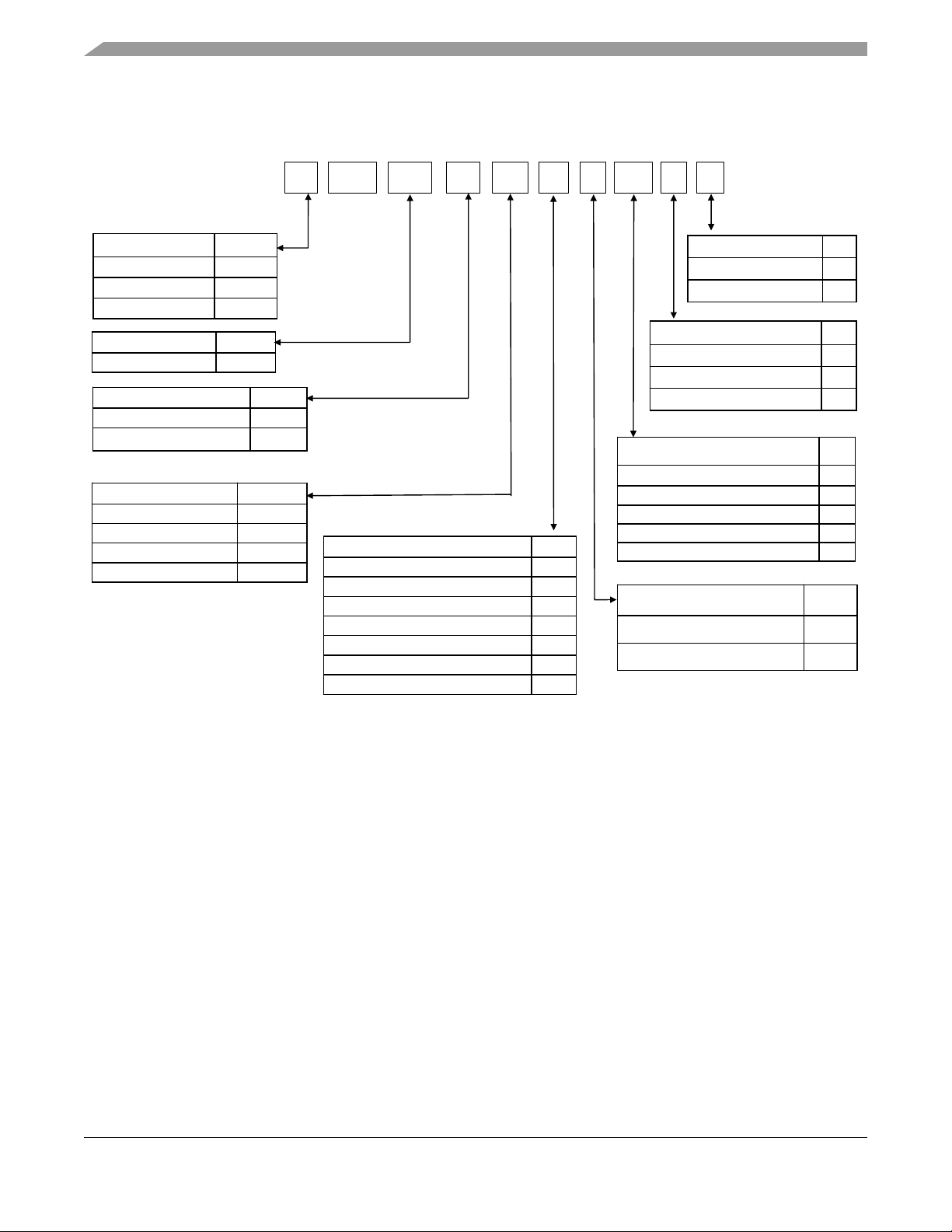
Figure 1 provides a cross-reference to match the revision code to the revision level marked on the device.
Temperature (Tj)
+
Consumer: 0 to + 95 °C D
Industrial: -40 to +105 °C C
Core Frequency $
400 MHz 4
500 MHz 5
600 MHz 6
Package Type VV
196MAPBGA, 12 x 12 mm, 0.8 mm pitch VJ
196MAPBGA, 10 x 10 mm, 0.65 mm pitch VL
144LQFP, 20 x 20 mm, 0.5 mm pitch AG
100LQFP, 14 x 14 mm, 0.5 mm pitch AF
80LQFP, 12 x 12 mm, 0.5 mm pitch AE
Qualification Level M
Prototype Samples P
Mass Production M
Special S
Part # series XX
i.MX RT RT
Tie %
Standard Feature 1
Full Feature 2
4MB Flash SIP 4
Enhanced Feature 5
Far Field AFE (e.g. for Alexa Voice Service) A
Facial Recognition F
Local Voice Control L
M IMX X X @ % + VV $ A
Family
@
First Generation RT family 1
Reserved 2-8
##
Sub-Family ##
RT101x 01
RT102x 02
RT105x 05
RT106x 06
Silicon Rev A
A0 A
A1 B
For details on the Arm® configuration used on this chip (including Arm module revisions), please see the
“Platform configuration” section of the “Arm Cortex®-M7 Platform” chapter of the i.MX RT1015
Crossover Processor Reference Manual (IMXRT1015RM).
2 NXP Semiconductors
Figure 1. Revision Level to Part Marking Cross-Reference
Chip Errata for the i.MX RT1015, Rev. 2, 01/2021
Page 3

Table 2 summarizes errata on the i.MX RT1015.
Table 2. Summary of Silicon Errata
Errata Name
ADC
ERR011164
ERR006223
ERR050143
ERR011572
ERR011207
ERR011377
ERR050130 PIT: Temporary incorrect value reported in LMTR64H register in lifetimer mode No fix scheduled 10
ADC: ADC_ETC fails to clear the ADC_ETC request signals automatically after
receiving DMA ack
CCM
CCM: Failure to resume from Wait/Stop mode with power gating No fix scheduled
CCM: SoC will enter low power mode before the Arm CPU executes WFI when
improper low power sequence is used
Cortex-M7
Cortex-M7: Write-Trough stores and loads may return incorrect data No fix scheduled
FlexSPI
FlexSPI: When FLEXSPI_AHBCR[PREFETCHEN] is set, incorrect data can be
returned in rare conditions
FlexSPI: FlexSPI DLL lock status bit not accurate due to timing issue No fix scheduled
PIT
Solution
No fix scheduled
No fix scheduled
No fix scheduled
Page
4
5
6
7
8
9
QTMR
ERR050194 QTMR: Overflow flag and related interrupt cannot be generated when the timer
is configured as upward count mode
SAI
ERR011096
ERR011150
ERR050144 SAI: Setting FCONT = 1 when TMR > 0 may not function correctly No fix scheduled 14
ERR011165
ERR006281
ERR050101
SAI: The internal bit clock cannot be generated when BCI = 1 No fix scheduled
SAI: Internally generated receive or transmit BCLK cannot be re-enabled if it is
first disabled when RCR2[DIV] or TCR2[DIV] > 0
SNVS
SNVS: Invalid ECC check failure No fix scheduled
USB
USB: Incorrect DP/DN state when only VBUS is applied No fix scheduled
USB: Endpoint conflict issue in device mode Fix in next revision
No fix scheduled 11
12
No fix scheduled
13
15
16
17
Chip Errata for the i.MX RT1015, Rev. 2, 01/2021
NXP Semiconductors 3
Page 4

ERR011164
ERR011164 ADC: ADC_ETC fails to clear the ADC_ETC request signals
automatically after receiving DMA ack
Description:
If enable ADC_ETC to trigger DMA transfer, the DMA transfer data send ack out. It does not clear
the request signals automatically and continue to trigger DMA.
Projected Impact:
This issue can lead to DMA failure when working with ADC_ETC.
Workarounds:
Configuring two DMA channels for ADC_ETC data transfer. The first DMA channel with low
priority triggered by ADC_ETC request is to transfer ADC_ETC data. The second DMA channel
with high priority links to the first channel is to clear request of ADC_ETC by writing
DMA_CTRL register. Both channel’s priority need to be higher than any channel used by other
peripherals. This solution is result in DMA to transfer ADC_ETC data twice for one request signal
and application need handle the redundant data properly.
Proposed Solution:
No fix scheduled
Software Status:
Software workaround is not in SDK.
Chip Errata for the i.MX RT1015, Rev. 2, 01/2021
4 NXP Semiconductors
Page 5

ERR006223 CCM: Failure to resume from Wait/Stop mode with power gating
Description:
When entering Wait/Stop mode with power gating of the Arm core(s), if an interrupt arrives during
the power-down sequence, the system could enter an unexpected state and fail to resume.
Projected Impact:
Device might fail to resume from low-power state.
Workarounds:
Use REG_BYPASS_COUNTER (RBC) to hold off interrupts when the PGC unit is in the middle
of the power-down sequence. The counter needs to be set/cleared only when there are no interrupts
pending. The counter needs to be enabled as close to the WFI (Wait For Interrupt) state as possible.
The following equation can be used to aid determination of the RBC counter value:
The PREG_BYPASS_COUNT value is equal or greater than 2.
Proposed Solution:
ERR006223
No fix scheduled
Software Status:
Software workaround is in SDK.
Chip Errata for the i.MX RT1015, Rev. 2, 01/2021
NXP Semiconductors 5
Page 6

ERR050143
ERR050143 CCM: SoC will enter low power mode before the Arm CPU
executes WFI when improper low power sequence is used
Description:
When software tries to enter the low power mode with the following sequence, SoC enters the low
power mode before the Arm CPU executes the WFI instructions.
• Set CCM_CLPCR[1:0] to 2’b00
• Arm CPU enters WFI
• Arm CPU wakes up from an interrupt event, which is masked by GPC or not visible to GPC,
such as an interrupt from local timer.
• Set CCM_CLPCR[1:0] to 2’b01 or 2’b10
• Arm CPU executes WFI
Before the last step, SoC enters the WAIT mode if CCM_CLPCR[1:0] is set to 2’b01, or enters
the STOP mode if CCM_CLPCR[1:0] is set to 2’b10.
Workarounds:
Software workaround:
1. Trigger IRQ #41 (IOMUX), which is always pending by setting IOMUXC_GPR_GPR1[12] bit
2. Unmask IRQ #41 in GPC before setting the CCM low power mode
3. Mask IRQ #41 right after the CCM low power mode is set (set CCM_CLPCR[1:0])
Proposed Solution:
No fix scheduled
Software Status:
Software workaround is in SDK
Chip Errata for the i.MX RT1015, Rev. 2, 01/2021
6 NXP Semiconductors
Page 7

ERR011572 Cortex-M7: Write-Trough stores and loads may return incorrect
data
Description:
Arm errata 1259864
If a particular sequence of stores and loads is performed on the Cortex-M7 core to Write-Through
memory, and some timing-based internal conditions are met, then a load may not have the last data
stored to that address.
This erratum can only occur if the loads and stores are to Write-Through memory. The following
methods enable write-through mode of the cache:
1. The Memory Protection Unit (MPU) has been programmed to set this address as
Write-Through.
2. The default memory map is being used, and this address is Write-Through in the default
memory map.
3. The memory is cacheable, and the CM7_CACR.FORCEWT bit is set.
4. The memory is cacheable, shared, and the CM7_CACR.SIWT bit is set.
Following sequence is required for this erratum to occur:
1. The address of interest must be in the data cache.
ERR011572
2. A Write-Through store is performed to the same double-word as the address of interest.
3. One of the following:
• A linefill is started (to a different cacheline to the address of interest) that allocates to the same
set and way as the address of interest.
• An Error Correcting Code (ECC) error is observed anywhere in the data cache.
• A data cache maintenance operation without a following Data Synchronization Barrier (DSB).
4. A store to the address of interest.
5. A load to the address of interest.
If certain specific timing conditions are met, the load get the data from the first store, or from what
was in the cache at the start of the sequence instead of the data from the second store.
Under these conditions, a load can return incorrect data.
Workarounds:
There is no direct workaround for this erratum.
Where possible, Arm is recommended that using the MPU to change the attributes on any
Write-Through memory to Write-Back memory. If this is not possible, it might be necessary to
disable the cache for sections of code that access Write-Through memory.
Proposed Solution:
No fix scheduled
Chip Errata for the i.MX RT1015, Rev. 2, 01/2021
NXP Semiconductors 7
Page 8

ERR011207
ERR011207 FlexSPI: When FLEXSPI_AHBCR[PREFETCHEN] is set,
incorrect data can be returned in rare conditions
Description:
When prefetching is enabled (FLEXSPI_AHBCR[PREFETCHEN]) for non-cacheable space,
there are conditions where write-read order might not be guaranteed. The problem can occur if data
is written and then read back using AHB interface, while a region containing the data location is
in the process of being loaded into the FlexSPI’s AHB Rx buffer.
Workarounds:
There are two workarounds:
• If FlexSPI space is not cached (configured as device or strongly-ordered type in the MPU), then
FLEXSPI_AHBRXBUFnCR0[PREFETCHEN] can be cleared.
• If the write is critical and the following read is to the same address, FlexSPI_STS0[SEQIDLE]
bit can be checked to make sure the write has completed (SEQIDLE is 1) before issuing the
subsequent read.
Proposed Solution:
No fix scheduled
Software Status:
Software workaround is not in SDK.
Chip Errata for the i.MX RT1015, Rev. 2, 01/2021
8 NXP Semiconductors
Page 9

ERR011377 FlexSPI: FlexSPI DLL lock status bit not accurate due to timing
issue
Description:
After configuring DLL and the lock status bit is set, the data may be wrong if read/write
immediately from FLEXSPI based external flash due to timing issue.
Workarounds:
Add delay time (100 NOP) again after the DLL lock status is set.
Proposed Solution:
No fix scheduled
Software Status:
No software workaround available
ERR011377
Chip Errata for the i.MX RT1015, Rev. 2, 01/2021
NXP Semiconductors 9
Page 10

ERR050130
ERR050130 PIT: Temporary incorrect value reported in LMTR64H register in
lifetimer mode
Description:
When the Programmable interrupt timer (PIT) module is used in lifetimer mode, timer 0 and timer
1 are chained and the timer load start value (LDVAL0[TSV] and LDVAL1[TSV]) are set according
to the application need for both timers. When timer 0 current time value (CVAL0[TVL]) reaches
0x0 and subsequently reloads to LDVAL0[TSV], then timer 1 CVAL1[TVL] should decrement by
0x1.
However this decrement does not occur until one cycle later, therefore a read of the PIT upper
lifetime timer register (LTMR64H) is followed by a read of the PIT lower lifetime timer register
(LTMR64L) at the instant when timer 0 has reloaded to LDVAL0[TSV] and timer 1 is yet to be
decremented in next cycle then an incorrect timer value in LTMR64H[LTH] is expected.
Workarounds:
In lifetimer mode, if the read value of LTMR64L[LTL] is equal to LDVAL0[TSV], then read both
LTMR64H and LTMR64L registers for one additional time to obtain the correct lifetime value.
Proposed Solution:
No fix scheduled
Software Status:
Software workaround is not in SDK.
Chip Errata for the i.MX RT1015, Rev. 2, 01/2021
10 NXP Semiconductors
Page 11

ERR050194 QTMR: Overflow flag and related interrupt cannot be generated
when the timer is configured as upward count mode
Description:
1. Overflow flag and related interrupt cannot be generated successfully in upward count mode.
2. When TMR_CTRL[OUTMODE] is set to 110b, OFLAG output is not cleared on counter
rollover when the timer counts upward.
Workarounds:
For item 1, using compare interrupt instead of overflow interrupt by setting compare value to
0xFFFF. The compare interrupt has the same timing effect as overflow interrupt in this way.
For item 2, there is no workaround.
Proposed Solution:
No fix scheduled
Software Status:
ERR050194
Software workaround is not in SDK.
Chip Errata for the i.MX RT1015, Rev. 2, 01/2021
NXP Semiconductors 11
Page 12

ERR011096
ERR011096 SAI: The internal bit clock cannot be generated when BCI = 1
Description:
When SAI transmitter or receiver is configured for the internal bit clock with BCI = 1, the bit clock
cannot be generated for either of the following two configurations:
1. SYNC = 00 and BCS = 0
2. SYNC = 01 and BCS = 1
Projected Impact:
The SAI bit clock cannot be generated properly.
Workarounds:
When SAI transmitter or receiver is configured for the internal bit clock with BCI = 1, using one
of the following two configurations:
1. SYNC = 01 and BCS = 0
2. SYNC = 00 and BCS = 1
Proposed Solution:
No fix scheduled
Software Status:
Software workaround is not in SDK.
Chip Errata for the i.MX RT1015, Rev. 2, 01/2021
12 NXP Semiconductors
Page 13

ERR011150 SAI: Internally generated receive or transmit BCLK cannot be
re-enabled if it is first disabled when RCR2[DIV] or TCR2[DIV] > 0
Description:
The receive or transmit bit clock (BCLK) is internally generated and enabled with DIV > 0. When
it is disabled, due to software or Stop mode entry, the BCLK is enabled again. Then the clock
cannot be generated.
Projected Impact:
The SAI bit clock cannot be generated.
Workarounds:
If the receive or transmit BCLK is internally generated and a DIV value is greater than 0, the SAI
must be reset before the BCLK is re-enabled. This is achieved by writing the SR bit in the
respective RCSR or TCSR register first to 1, and then immediately write it to 0.
Proposed Solution:
No fix scheduled
ERR011150
Software Status:
Software workaround is not in SDK.
Chip Errata for the i.MX RT1015, Rev. 2, 01/2021
NXP Semiconductors 13
Page 14

ERR050144
ERR050144 SAI: Setting FCONT = 1 when TMR > 0 may not function correctly
Description:
When FCONT = 1 the transmitter will recover after a FIFO error when the FIFO is no longer empty
and starting again from the same word in the following frame where the error occurred.
Configuring TMR > 0 will configure one or more words in the frame to be masked (nothing
transmitted during that slot). If anything other than the last word(s) in the frame are masked when
FCONT = 1 and a FIFO Error Flag is set, then the transmitter will not recover and will set FIFO
Error Flag during each frame.
Workarounds:
To avoid this issue, set FCONT in TCR4 to be 0.
Proposed Solution:
No fix scheduled
Software Status:
Software workaround is not in SDK.
Chip Errata for the i.MX RT1015, Rev. 2, 01/2021
14 NXP Semiconductors
Page 15

ERR011165 SNVS: Invalid ECC check failure
Description:
When setting LPMKCR[ZMK_ECC_EN] bit, it may generate ZMK ECC Check Failure Violation
even the ZMK and its ECC values are correct.
Projected Impact:
ZMK is not usable in case the ZMK ECC check is enabled.
Workarounds:
Not enable ZMK ECC check
Proposed Solution:
No fix scheduled
Software Status:
Software workaround is not in SDK.
ERR011165
Chip Errata for the i.MX RT1015, Rev. 2, 01/2021
NXP Semiconductors 15
Page 16

ERR006281
ERR006281 USB: Incorrect DP/DN state when only VBUS is applied
Description:
When VBUS is applied without any other supplies, incorrect communication states are possible on
the data (DP/DN) signals. If VDDHIGH_IN is supplied, the problem is removed.
Projected Impact:
This issue primarily impacts applications using charger detection to signal power modes to a PMIC
in an undercharged battery scenario where the standard USB current allotment is not sufficient to
boot the system.
Workarounds:
Apply VDDHIGH_IN if battery charge detection is needed. Otherwise, disable charger detection
by setting the EN_B bit in USB_ANALOG_USBx_CHRG_DETECTn to 1.
Proposed Solution:
No fix scheduled
Software Status:
Software workaround is not in SDK.
Chip Errata for the i.MX RT1015, Rev. 2, 01/2021
16 NXP Semiconductors
Page 17

ERR050101 USB: Endpoint conflict issue in device mode
Description:
An endpoint conflict occurs when the USB is working in device mode during an isochronous
communication.
When the endpointA IN direction is an isochronous IN endpoint, and the host sends an IN token to
endpointA on another device, then the OUT transaction may be missed regardless the OUT
endpoint number. Generally, this occurs when the device is connected to the host through a hub and
other devices are connected to the same hub.
The affected OUT endpoint can be either control, bulk, isochronous, or an interrupt endpoint. After
the OUT endpoint is primed, if an IN token to the same endpoint number on another device is
received, then the OUT endpoint may be unprimed (cannot be detected by software), which causes
this endpoint to no longer respond to the host OUT token, and thus, no corresponding interrupt
occurs.
Workarounds:
Do not connect to a hub in case ISO IN endpoint(s) is used. When the hub(s) must be connected in
this case, the endpoint number(s) of the ISO IN endpoint(s) should be different from the endpoint
number(s) of any types of IN endpoint(s) used in any other device(s) connected to the same host.
ERR050101
Proposed Solution:
Fix in next revision
Chip Errata for the i.MX RT1015, Rev. 2, 01/2021
NXP Semiconductors 17
Page 18

How To Reach Us
Home Page:
nxp.com
Web Support:
nxp.com/support
Limited warranty and liability — Information in this document is provided solely to enable
system and software implementers to use NXP products. There are no express or implied
copyright licenses granted hereunder to design or fabricate any integrated circuits based on the
information in this document. NXP reserves the right to make changes without further notice to
any products herein.
NXP makes no warranty, representation, or guarantee regarding the suitability of its products
for any particular purpose, nor does NXP assume any liability arising out of the application
or use of any product or circuit, and specifically disclaims any and all liability, including
without limitation consequential or incidental damages. “Typical” parameters that may be
provided in NXP data sheets and/or specifications can and do vary in different applications,
and actual performance may vary over time. All operating parameters, including “typicals,”
must be validated for each customer application by customer's technical experts. NXP does
not convey any license under its patent rights nor the rights of others. NXP sells products
pursuant to standard terms and conditions of sale, which can be found at the following address:
nxp.com/SalesTermsandConditions.
Right to make changes - NXP Semiconductors reserves the right to make changes to information
published in this document, including without limitation specifications and product descriptions,
at any time and without notice. This document supersedes and replaces all information supplied
prior to the publication hereof.
Security — Customer understands that all NXP products may be subject to unidentified
or documented vulnerabilities. Customer is responsible for the design and operation of its
applications and products throughout their lifecycles to reduce the effect of these vulnerabilities
on customer’s applications and products. Customer’s responsibility also extends to other open
and/or proprietary technologies supported by NXP products for use in customer’s applications.
NXP accepts no liability for any vulnerability. Customer should regularly check security updates
from NXP and follow up appropriately. Customer shall select products with security features
that best meet rules, regulations, and standards of the intended application and make the
ultimate design decisions regarding its products and is solely responsible for compliance with
all legal, regulatory, and security related requirements concerning its products, regardless of
any information or support that may be provided by NXP. NXP has a Product Security Incident
Response Team (PSIRT) (reachable at PSIRT@nxp.com) that manages the investigation,
reporting, and solution release to security vulnerabilities of NXP products.
NXP, the NXP logo, NXP SECURE CONNECTIONS FOR A SMARTER WORLD,
COOLFLUX,EMBRACE, GREENCHIP, HITAG, ICODE, JCOP, LIFE, VIBES, MIFARE, MIFARE
CLASSIC, MIFARE DESFire, MIFARE PLUS, MIFARE FLEX, MANTIS, MIFARE ULTRALIGHT,
MIFARE4MOBILE, MIGLO, NTAG, ROADLINK, SMARTLX, SMARTMX, STARPLUG, TOPFET,
TRENCHMOS, UCODE, Freescale, the Freescale logo, AltiVec, CodeWarrior, ColdFire,
ColdFire+, the Energy Efficient Solutions logo, Kinetis, Layerscape, MagniV, mobileGT, PEG,
PowerQUICC, Processor Expert, QorIQ, QorIQ Qonverge, SafeAssure, the SafeAssure logo,
StarCore, Symphony, VortiQa, Vybrid, Airfast, BeeKit, BeeStack, CoreNet, Flexis, MXC, Platform
in a Package, QUICC Engine, Tower, TurboLink, EdgeScale, EdgeLock, eIQ, and Immersive3D
are trademarks of NXP B.V. All other product or service names are the property of their
respective owners. AMBA, Arm, Arm7, Arm7TDMI, Arm9, Arm11, Artisan, big.LITTLE, Cordio,
CoreLink, CoreSight, Cortex, DesignStart, DynamIQ, Jazelle, Keil, Mali, Mbed, Mbed Enabled,
NEON, POP, RealView, SecurCore, Socrates, Thumb, TrustZone, ULINK, ULINK2, ULINK-ME,
ULINK-PLUS, ULINKpro, µVision, Versatile are trademarks or registered trademarks of Arm
Limited (or its subsidiaries) in the US and/or elsewhere. The related technology may be protected
by any or all of patents, copyrights, designs and trade secrets. All rights reserved. Oracle
and Java are registered trademarks of Oracle and/or its affiliates. The Power Architecture and
Power.org word marks and the Power and Power.org logos and related marks are trademarks
Table continues on the next page...
Page 19

and service marks licensed by Power.org. M, M Mobileye and other Mobileye trademarks or logos
appearing herein are
trademarks of Mobileye Vision Technologies Ltd. in the United States, the
EU and/or other jurisdictions.
©
NXP B.V. 2019-2021.
For more information, please visit: http://www.nxp.com
For sales office addresses, please send an email to: salesaddresses@nxp.com
All rights reserved.
Date of release: 19 Feb 2021
Document identifier:
IMXRT1015CE
 Loading...