

Page 1

AN13204
i.MX RT1170 ECC Application
Rev. 0 — 03/2021
1 Introduction
i.MX RT1170 covers auto area, so, compared with previous i.MX RT product
like i.MX RT1060, the ECC feature is enhanced a lot. For use case with high
safety level requirement, we need to detect the ECC error when it happens and
informs application system to decide how to process this error.
This document discusses the ECC application on memory, including TCM,
Cache, OCRAM and external memory, and shares some key points and
experience. It does not cover ECC application on peripherals like FlexSPI,
Fuse, OCOTP, CSI, MIPI CSI, MIPI DSI, ENET QOS and FLEX CAN.
For memory ECC application on i.MX RT1170, we need to consider:
• On which memory to apply ECC?
i.MX RT 1170 contains the following memory types:
— TCM
Application Note
Contents
1 Introduction......................................1
2 i.MX RT1170 ECC feature list......... 1
3 Fuse setting and SW configuration
related with ECC feature................. 2
4 Fuse setting implementation by MCU
boot utility tool................................. 3
5 Preloading operation....................... 5
6 ECC error injection..........................6
7 SDK example related with ECC
feature............................................. 6
8 Attentions for i.MX RT1170 ECC
application....................................... 7
9 References......................................7
10 Revision history...............................7
— Cache
— OCRAM
— External memory
• How to inject/capture ECC error?
• Fuse setting and SW configuration related with ECC.
• ROM feature related with ECC.
2 i.MX RT1170 ECC feature list
Table 1 lists i.MXRT1170 ECC features.
Table 1. i.MX RT1170 ECC feature list
Items ECC feature
[CM7] TCM from CM7 FlexRAM
[CM7] Cache
[CM4] TCM/LMEM
ITCM: 64bit data + 8bit ECC
DTCM: 32bit data + 7bit ECC
I-Cache: 64 bit data + 8 bit ECC
D-Cache: 32 bit data + 7 bit ECC
Hsiao odd-weight column criteria ECC code
32 bit data + 7 bit ECC
Table continues on the next page...
Page 2

NXP Semiconductors
Table 1. i.MX RT1170 ECC feature list (continued)
Items ECC feature
[CM4] Cache Parity check
Fuse setting and SW configuration related with ECC feature
[CM7/CM4] OCRAM1/OCRAM2
[CM7/CM4] OCRAM from CM7 FlexRAM Hsiao Hamming algorithm 64 bit data + 8 bit ECC
[CM7/CM4] OCRAM from CM4 TCM/LMEM
[CM7/CM4] XECC
Hsiao Hamming algorithm
64 bit data + 8 bit ECC
Hsiao odd-weight column criteria ECC code
32 bit data + 7 bit ECC
Hsiao Hamming algorithm 4 bit data + 4 bit ECC
Extend to be: 32 bit data + 32 bit ECC
3 Fuse setting and SW configuration related with ECC feature
To enable ECC feature, enable related fuse settings and software configurations.
Table 2 lists fuse settings related with ECC.
Table 2. Fuse settings related with ECC
Fuse map Function
0x840[2] MECC, for OCRAM1/OCRAM2
0x840[3] XECC for external memory like SDRAM, SRAM, FlexSPI device.
0x840[15] CM7 Flex RAM ECC(Include CM7 Flex RAM TCM and CM7 Flex RAM OCRAM)
0x950[0] ROM preloading
Table 3 lists the software configurations.
Table 3. SW configurations related with ECC
Items SW config requirement Executed by ROM?
SCB->ITCMCR |
= SCB_ITCMCR_RMW_Msk;
[CM7] TCM from CM7 FlexRAM
[CM7] Cache CACR &= ~ECCEN_Msk No, enabled by default.
[CM4] TCM/LMEM
SCB->DTCMCR |
= SCB_DTCMCR_RMW_Msk;
FLEXRAM_CTRL |= TCM_ECC_EN_Msk
LMDR0 |= 0xB;
LMDR1 |= 0xB;
(By CM4 only)
Yes, if 0x840[15] fused.
Yes, if 0x840[2] fused.
Table continues on the next page...
i.MX RT1170 ECC Application, Rev. 0, 03/2021
Application Note 2 / 8
Page 3
NXP Semiconductors
Table 3. SW configurations related with ECC (continued)
Items SW config requirement Executed by ROM?
LMDR2 |= 0xF0;
Fuse setting implementation by MCU boot utility tool
[CM4] Cache
[CM7/CM4] OCRAM1/OCRAM2
[CM7/CM4] OCRAM from CM7 FlexRAM FLEXRAM_CTRL |= OCRAM_ECC_EN_Msk No
[CM7/CM4] OCRAM from CM4
TCM/LMEM
[CM7/CM4] XECC XECC_ECC_CTRL |= 7; No
LMDR3 |= 0xF0;
(By CM4 only)
MECC1_PIPE_ECC_EN |= ECC_EN_Msk
MECC2_PIPE_ECC_EN |= ECC_EN_Msk
LMDR0 |= 0xB;
LMDR1 |= 0xB;
(By CM4 only)
No
Yes, if 0x840[2] fused.
Yes, if 0x840[2] fused.
4 Fuse setting implementation by MCU boot utility tool
MCU boot utility tool is used for fuse setting.
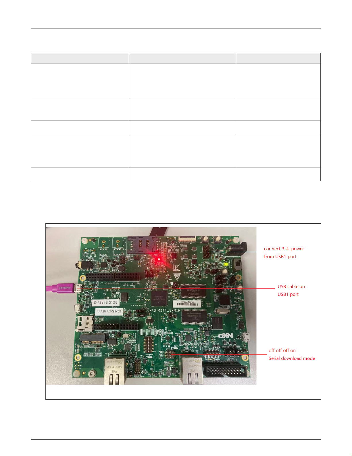
1. Config boot mode, config power jumper (not a must), and connect USB1 port, as shown in Figure 1.
Figure 1. Hardware setup
2. Launch MCU boot utility tool, with PID and VID recognized correctly.
i.MX RT1170 ECC Application, Rev. 0, 03/2021
Application Note 3 / 8
Page 4

NXP Semiconductors
Figure 2. PID and VID recognized
3. Uncheck One Step in Figure 2.
4. In Figure 2, click Connect to ROM and Figure 3 appears.
Fuse setting implementation by MCU boot utility tool
Figure 3. Connect to Flashloader
5. In Figure 3, click Connect to Flashloader, and go to the eFuse Operation Utility panel, as shown in Figure 4.
i.MX RT1170 ECC Application, Rev. 0, 03/2021
Application Note 4 / 8
Page 5

NXP Semiconductors
Figure 4. eFuse Operation Utility panel
Preloading operation
6. In Figure 4, press the Scan button, and the fuse values are loaded, as shown in Figure 5. You can edit fuse values and press
the Burn button to implement new fuse setting to chip.
Figure 5. Fuse values
5 Preloading operation
For ECC memory region, before reading, all the memory space must be written to fill correct ECC value. Otherwise ECC error
events may occur when reading the memory. The first write operation is also called preloading.
i.MX RT1170 ECC Application, Rev. 0, 03/2021
Application Note 5 / 8
Page 6

NXP Semiconductors
ROM covers some preloading for some memory region depending on the fuse settings, as shown in Table 4.
For memory without ROM preloading, perform preloading in the ECC memory initialization.
Table 4. ROM preloading
Items Preloading by ROM
[CM7] TCM from CM7 FlexRAM Yes, if 0x840[15] and 950[0] fused.
[CM7] Cache —
[CM4] TCM/LMEM Yes, if 0x840[2] and 950[0] fused
[CM4] Cache —
[CM7/CM4] OCRAM1/OCRAM2 Yes, if 0x840[2] and 950[0] fused
[CM7/CM4] OCRAM from CM7 FlexRAM —
[CM7/CM4] OCRAM from CM4 TCM/LMEM Yes, if 0x840[2] and 950[0] fused
[CM7/CM4] XECC —
ECC error injection
6 ECC error injection
Error injection provides a way for debug purpose. Typically, we cannot see ECC error in application. To validate that ECC feature
is working as expected, we can inject some error bits into memory. When accessing the memory with error bits, we can see
ECC failure. After ECC error injection finishes, the ECC error injection feature must be disabled and then the system can keep
running correctly.
Table 5 lists the memory regions which support ECC error injection.
Table 5. ECC error injection
Items Error injection support
[CM7] TCM from CM7 FlexRAM √
[CM7] Cache —
[CM4] TCM/LMEM —
[CM4] Cache —
[CM7/CM4] OCRAM1/OCRAM2 √
[CM7/CM4] OCRAM from CM7 FlexRAM √
[CM7/CM4] OCRAM from CM4 TCM/LMEM —
[CM7/CM4] XECC √
7 SDK example related with ECC feature
In SDK, the following examples show the details about how to trigger ECC error by ECC error injection:
•
boards\evkmimxrt1170\driver_examples\mecc
i.MX RT1170 ECC Application, Rev. 0, 03/2021
Application Note 6 / 8
Page 7

NXP Semiconductors
Attentions for i.MX RT1170 ECC application
•
boards\evkmimxrt1170\driver_examples\xecc
•
boards\evkmimxrt1170\driver_examples\flexram\flexram_ecc
To run these example, fuse the bits mentioned in Table 2 first.
NOTE
Fuse operation is irreversible.
In addition, a demo code for MECC, AN13204SW, is provided together with this document to show the complete flow for:
• Error injection
• Disable error injection (After error injection, error injection feature must be disable for application)
• ECC error trigger and catch
It covers both MECC1 and MECC2.
8 Attentions for i.MX RT1170 ECC application
• For memory region with ECC enabled, write all the memory regions before reading. Otherwise, ECC failure may happen.
• Some memory is organized by 64 bit width (see Table 1 for details), so even a 32 bit write in fact is executed as:
1. Read 64 bit
2. Modify 32 bit in it
3. Write 64 bit back
So, in some condition, even a 32 bit write operation may trigger ECC error event by the first 64 bit reading accompany with it.
• The preloading operations listed in Table 4 are executed by ROM only when POR is detected. For some reset cases
with SNVS always powered on, ROM would not do preloading. After reset, it may lead to memory access ECC failure.
In SDK code, there is an operation to record and clear SRSR register. It is in SystemInit() function, controlled by
ROM_ECC_ENABLED macro, which is disabled by default. For ECC application, ROM_ECC_ENABLED should be enabled by
user. For application not based on NXP SDK, developer should take this into consideration for ECC application.
• ECC error injection does not discriminate master. Do not perform dynamic ECC error injection which will spoil data from
peripheral like DMA or other bus masters. Suggest to inject some error into specified memory address at the beginning,
and then disable ECC error injection feature during running time.
• For OCRAM mapped from CM4 TCM/LMEM:
— The enable/disable operation can only be done by CM4 core.
— For a single core chip, the ECC feature is enabled by default.
— It cannot trigger ECC interrupt for CM7 core (ERR050634).
9 References
•
i.MX RT1170 Processor Reference Manual
(document IMXRT1170RM)
10 Revision history
Revision number Date Substantive changes
1 03/2021 Initial release
i.MX RT1170 ECC Application, Rev. 0, 03/2021
Application Note 7 / 8
Page 8

How To Reach Us
Home Page:
nxp.com
Web Support:
nxp.com/support
Information in this document is provided solely to enable system and software implementers to use NXP products. There
are no express or implied copyright licenses granted hereunder to design or fabricate any integrated circuits based on the
information in this document. NXP reserves the right to make changes without further notice to any products herein.
NXP makes no warranty, representation, or guarantee regarding the suitability of its products for any particular purpose, nor
does NXP assume any liability arising out of the application or use of any product or circuit, and specifically disclaims any
and all liability, including without limitation consequential or incidental damages. “Typical” parameters that may be provided
in NXP data sheets and/or specifications can and do vary in different applications, and actual performance may vary over
time. All operating parameters, including “typicals,” must be validated for each customer application by customer's technical
experts. NXP does not convey any license under its patent rights nor the rights of others. NXP sells products pursuant to
standard terms and conditions of sale, which can be found at the following address: nxp.com/SalesTermsandConditions.
Right to make changes - NXP Semiconductors reserves the right to make changes to information published in this
document, including without limitation specifications and product descriptions, at any time and without notice. This
document supersedes and replaces all information supplied prior to the publication hereof.
Security — Customer understands that all NXP products may be subject to unidentified or documented vulnerabilities.
Customer is responsible for the design and operation of its applications and products throughout their lifecycles to reduce
the effect of these vulnerabilities on customer’s applications and products. Customer’s responsibility also extends to other
open and/or proprietary technologies supported by NXP products for use in customer’s applications. NXP accepts no
liability for any vulnerability. Customer should regularly check security updates from NXP and follow up appropriately.
Customer shall select products with security features that best meet rules, regulations, and standards of the intended
application and make the ultimate design decisions regarding its products and is solely responsible for compliance with all
legal, regulatory, and security related requirements concerning its products, regardless of any information or support that
may be provided by NXP. NXP has a Product Security Incident Response Team (PSIRT) (reachable at PSIRT@nxp.com)
that manages the investigation, reporting, and solution release to security vulnerabilities of NXP products.
NXP, the NXP logo, NXP SECURE CONNECTIONS FOR A SMARTER WORLD, COOLFLUX,EMBRACE, GREENCHIP,
HITAG, ICODE, JCOP, LIFE, VIBES, MIFARE, MIFARE CLASSIC, MIFARE DESFire, MIFARE PLUS, MIFARE FLEX,
MANTIS, MIFARE ULTRALIGHT, MIFARE4MOBILE, MIGLO, NTAG, ROADLINK, SMARTLX, SMARTMX, STARPLUG,
TOPFET, TRENCHMOS, UCODE, Freescale, the Freescale logo, AltiVec, CodeWarrior, ColdFire, ColdFire+, the Energy
Efficient Solutions logo, Kinetis, Layerscape, MagniV, mobileGT, PEG, PowerQUICC, Processor Expert, QorIQ, QorIQ
Qonverge, SafeAssure, the SafeAssure logo, StarCore, Symphony, VortiQa, Vybrid, Airfast, BeeKit, BeeStack, CoreNet,
Flexis, MXC, Platform in a Package, QUICC Engine, Tower, TurboLink, EdgeScale, EdgeLock, eIQ, and Immersive3D are
trademarks of NXP B.V. All other product or service names are the property of their respective owners. AMBA, Arm, Arm7,
Arm7TDMI, Arm9, Arm11, Artisan, big.LITTLE, Cordio, CoreLink, CoreSight, Cortex, DesignStart, DynamIQ, Jazelle,
Keil, Mali, Mbed, Mbed Enabled, NEON, POP, RealView, SecurCore, Socrates, Thumb, TrustZone, ULINK, ULINK2,
ULINK-ME, ULINK-PLUS, ULINKpro, μVision, Versatile are trademarks or registered trademarks of Arm Limited (or its
subsidiaries) in the US and/or elsewhere. The related technology may be protected by any or all of patents, copyrights,
designs and trade secrets. All rights reserved. Oracle and Java are registered trademarks of Oracle and/or its affiliates. The
Power Architecture and Power.org word marks and the Power and Power.org logos and related marks are trademarks and
service marks licensed by Power.org.
©
NXP B.V. 2021. All rights reserved.
For more information, please visit: http://www.nxp.com
For sales office addresses, please send an email to: salesaddresses@nxp.com
Date of release: 03/2021
Document identifier: AN13204
 Loading...