

Page 1

AN12524
Migration from FXTH87/87E to NTM88
Rev. 3 — 22 March 2021 Application note
Document information
Information Content
Keywords FXTH87/87E, NTM88, Migration
Abstract This document presents the main differences between FXTH87/87E and
NTM88 from a software application point of view.
Page 2
NXP Semiconductors
AN12524
Migration from FXTH87/87E to NTM88
Revision history
Revision Date Description
3 20210322 • Global: Performed minor grammatical, content, and typographic changes throughout.
• Inserted "Document information" table on the first page.
• Relocated the "Revision history" from the end of the document to the beginning to
conform to NXP document content guidelines.
• Section 2, replaced footnote in the first paragraph with a document reference and
added document references for AN12523 in the second paragraph directing user to
the new Section 16 "References".
• Section 3, removed the note below Table 1.
• Section 4.1, revised as follows:
– Revised "...FFh, security register configured to 82h, and reserved bytes2 in portions
of FLASH from FFDCh to FFDFh." to "FFh and security register configured to 82h."
and removed footnote 2.
– Figure 1, revised the image.
• Section 6, Table 3, revised the first row deleting "FXTH87/87E" from the first column,
removed ", documented in the NTM88 firmware user guide" from the third column and
added "TPMS_E_READ_ACCEL" to the second row first cell.
• Section 7, revised as follows:
– Revised "...the user does not have to handle the stack allocation, it can be placed
at any address by the linker." to "...the user does not have to force the stack top
address to 28Fh anymore."
– Table 4 revised "The user does not have to handle stack allocation." to "The user
does not have to force the stack top address to 28Fh."
• Section 8, replaced the footnote in the first paragraph with a document reference
directing user to the new Section 16 "References".
• Section 9.2, revised "part numbers" to "devices" in the third paragraph, and the the
last row of Table 6 and revised the footnote in Table 6.
• Section 10 "GPIOs", Section 11 "Conditions to raise LF receive error flag", and
Section 12 "RF pre-charge", three new sections added.
• Section 16, inserted new reference section.
2 20191210 • Section 2, revised the second paragraph removing the word "production".
• Section 4, revised the first and third paragraphs and Table 2.
• Section 4.1, revised as follows:
– Revised all paragraphs.
– Revised the image and caption for Figure 1.
– Removed Figure 2, captioned "Memory map of the PTM88 and NTM88 using
library model."
• Section 5, revised the first and second paragraphs.
• Section 6, revised the last row of Table 3 and removed note before table.
• Section 7, added a note after the last bullet.
• Section 9.2, revised entire section including Table 6.
• Section 13, revised entire section.
1 20190722 Initial release
AN12524 All information provided in this document is subject to legal disclaimers. © NXP B.V. 2021. All rights reserved.
Application note Rev. 3 — 22 March 2021
2 / 15
Page 3
NXP Semiconductors
1 Introduction
This document presents the main differences between FXTH87/87E and NTM88 from a
software application point of view.
Note: Unless otherwise stated, the term “NTM88” refers to both the engineering
samples (PTM88) and the production samples (NTM88). In Section 4 "Memory map
and application model", a distinction is made between the engineering and production
samples. In all other sections, the information applies to both the engineering and
production samples.
2 Getting started
AN12524
Migration from FXTH87/87E to NTM88
The IDE to develop NTM88 applications remains CodeWarrior. A patch
installed to have access to the NTM88 target.
From a software application point of view, NTM88 supports only Library Model
Applications. NXP does not program NTM88 samples with embedded firmware functions.
Users familiar with Firmware Model Applications can refer to AN12523
provides information on the differences between these two models and how to migrate
applications from a firmware model to a library model.
3 Pressure and acceleration transfer functions
FXTH87 and FXTH87E have different transfer functions for pressure and acceleration.
For pressure and acceleration, FXTH87 and FXTH87E use a 10-bit representation
for raw measurement of pressure and acceleration. However, for compensated
measurement, a 9-bit representation is used.
NTM88 uses a 12-bit representation for raw measurement and a 10-bit representation for
compensated measurement of pressure and acceleration.
Refer to the appropriate data sheet for actual compensated transfer functions because
they differ from one part number to another.
Table 1. Bit representation of raw pressure and acceleration and compensated pressure
and acceleration
Representation of raw
pressure and acceleration
FXTH87 and FXTH87E 10 bits 9 bits
NTM88 12 bits 10 bits
[1]
must be
[2]
. AN12523
Representation of compensated
pressure and acceleration
[2]
4 Memory map and application model
The memory map is the same between the FXTH87 and FXTH87E, but different for the
NTM88.
During the production of FXTH87 and FXTH87E devices, NXP programs the firmware
and trim between E000h and FFFFh. The user may choose to develop either firmwarebased applications or library-based applications. For firmware-based applications, the
embedded firmware is used by the application. With library-based applications, the user
erases the embedded firmware and reprograms the functions used by the application.
AN12524 All information provided in this document is subject to legal disclaimers. © NXP B.V. 2021. All rights reserved.
Application note Rev. 3 — 22 March 2021
3 / 15
Page 4

NXP Semiconductors
The PTM88xxxS alpha-engineering samples have been shipped with an embedded
firmware. This is indicated for reference only as these samples are not distributed
anymore. NXP programs PTM88xxx5 and NTM88 production samples with trim only.
Without programmed firmware functions, only the library model is applicable for
PTM88xx5 and NTM88.
Table 2. Engineering and production sample firmware and programming
FXTH87 and FXTH87E N/A
(alpha samples – not
provided anymore)
PTM88xxxS
PTM88xxx5
and NTM88
AN12524
Migration from FXTH87/87E to NTM88
Engineering samples Production samples
Firmware and trim programmed by
(already released to production)
Firmware and trim
programmed by NXP
between E800h and FFFFh.
No firmware function programmed. NXP programs only trim between
FD40h and FDFFh. See Section 4.1. Only library model can be used.
NXP between E000h and FFFFh
Firmware and library
model can be used.
N/A
(alpha samples not
released to production)
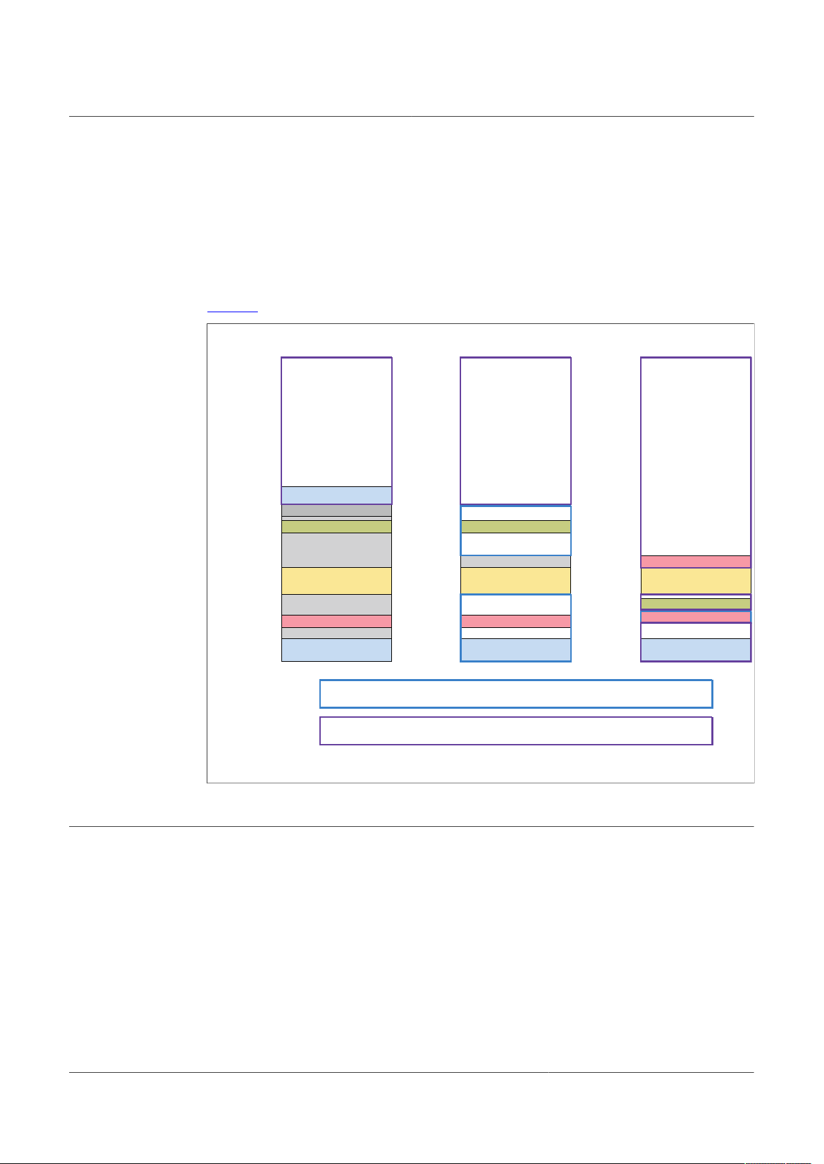
4.1 Overview of the memory maps
FXTH87 and FXTH87E samples shipped by NXP are programmed with an embedded
firmware containing:
• the firmware functions,
• a jump table allowing user application calls to the firmware functions,
• trim coefficients and
• firmware interrupt vectors.
For these products, customers may choose to
• use the firmware model by keeping the embedded firmware.
• use the library model by erasing the embedded firmware (trim page excluded) and
adding firmware functions used by the application from the firmware library.
Refer to AN12523
In contrast, NTM88 samples are programmed only with:
• Trim coefficients from FD40h to FDFFh that must not be erased. It is important to
preserve the whole page from FC00h to FDFFh and ensure that the application does
not erase the page;
• Protection register configured to FFh and security register configured to 82h.
When the application reprograms the interrupt vectors, the whole page from FE00h to
FFFFh is erased. The erasure implies the protection and security registers are set to
FFh. A security register set to FFh secures the device and prevent any further BDM
access. The user must ensure that the application code configures the security register
to an unsecure status value, for example to value 82h.
[2]
for additional information.
The rest of the flash is left empty. For NTM88 samples, only the library model can be
used since no firmware functions are programmed.
In NTM88, the section from FC00h to FD3Fh is indicated as “one-time programmable”.
NXP does not program this section and the section may be programmed one time since it
is empty. However, after "one-time programing," the user cannot erase the section. Flash
may only be erased 512 bytes by 512 bytes. Erasing the FC00h to FD3Fh section would
AN12524 All information provided in this document is subject to legal disclaimers. © NXP B.V. 2021. All rights reserved.
Application note Rev. 3 — 22 March 2021
4 / 15
Page 5
NXP Semiconductors
aaa-0 34413
FXTH 87/87E using a
firmware-bas ed applic ation
Jump tabl e
Firmware ver sion
E0A0- E0A3
E000 -E092 /E08 F
*
*
E092 for F XTH87xx1x,
E08F for FXTH87x x02
DFE0- DFDF
C000 -DFDF
FD40 -FDFF FD40 -FDFF
FFB0- FFBF
FFE0- FFFF
E0A0- E0A3
C00 0-E0 9F
FC00 -FD3F
FFB0- FFBF
FFE0- FFFF
Protect ion and secu rity
Firmwar e functio ns
Firmwar e interrup t vectors
Appli cation inte rrupt vec tors
Trim section
Librar y version
Protecti on and secu rity
Firmware n ot erasabl e
Interru pt vector s
Trim section
Application cod e
+
Firmware functions from
the fir mware libr ary
+
Function s from the
applicat ion libra ries
Applic ation cod e
+
Functions f rom the
applica tion libr aries
FXTH 87/87E using a
librar y-based applica tion
FD40- FDFF
C00 0-FB FF
FC00- FD3F
FFB0- FFBF
FFE0- FFFF
Protecti on and secu rity
FFAC-FFAF Librar y version
One- time progr ammable
Interru pt vector s
Trim section
Applic ation cod e
+
Firmware function s from
the fir mware libr ary
+
Functions f rom the
applica tion libr aries
NTM88 using a
librar y-base d applica tion
Portions of FLASH progra mmed by NXP at p roducti on that are er ased and over wri tten by
librar y-based applica tions
Not progr ammed by NX P i.e. empty wh en customers recei ve the sampl es
erase the trim coefficients section which must not be done. Erasing the trim coefficients
section results in non-functional sensors.
The NTM88 firmware function TPMS_FLASH_WRITE prevents write access between
FD40h and FDFFh. TPMS_FLASH_WRITE may be used to write bytes between FC00h
and FD3Fh with NTM88. In contrast, the FXTH firmware write access is forbidden
in the whole trim page between FC00h and FDFFh. With both FXTH and NTM88,
TPMS_FLASH_ERASE function cannot erase the trim page from FC00h to FDFFh.
Figure 1 shows the memory map of FXTH87/87E and NTM88.
AN12524
Migration from FXTH87/87E to NTM88
5 Firmware version and derivative descriptor bytes
AN12524 All information provided in this document is subject to legal disclaimers. © NXP B.V. 2021. All rights reserved.
Application note Rev. 3 — 22 March 2021
Figure 1. Memory map of the FXTH87/87E and NTM88 using firmware and library model
For FXTH87 and FXTH87E, the firmware version and the derivative descriptor bytes are
documented as CODE0 and CODE1 in the data sheet. The firmware version CODE0 is
programmed by NXP at production with the version of the embedded firmware. When
using library model applications, the library version overwrites the firmware version.
For NTM88, they are documented in the data sheet as CODEF and CODEH and
are placed at different addresses. The byte CODEF is not programmed by NXP at
production. It contains the firmware library version after the user has programmed an
application in the device.
NXP recommends customers always use the function TPMS_READ_ID to read these
bytes. NXP does not recommend a direct read from memory because the location in
FXTH87/87E is different from NTM88 and NXP may change the location.
5 / 15
Page 6

NXP Semiconductors
6 Firmware and application libraries
NXP provides functions to ease customer software application development. For
FXTH87/87E, the functions are available in the embedded firmware (firmware model) or
firmware library (library model), in the Configurable library and the new LFOCAL library.
For NTM88, the FXTH87/87E functions have been adapted for NTM88 and are available,
however, some functions are placed in different libraries. Table 3 summarizes where to
find the functions for all families.
Table 3. Function availability: firmware model vs. library model
(firmware or library model)
Firmware functions listed
in the firmware user guide
Functions TPMS_E_READ_
ACCEL to take faster
acceleration measurements
(for algorithms)
Functions to operate the
Free Running Counter
New LFOCAL
library functions
Function TPMS_FLASH_
CHECK and functions to
calculate a 16-bit CRC
Migration from FXTH87/87E to NTM88
FXTH87 and FXTH87E
Available in the Embedded
Firmware (firmware model)
or the FXTH Firmware
Library (library model)
Available in the FXTH
Configurable Library
Available in the FXTH
Configurable Library
Available in the FXTH
New LFOCAL Library
Available in the Embedded
Firmware (firmware model)
or the FXTH Firmware
Library (library model)
AN12524
NTM88
(library model)
Available in the NTM88
Firmware Library
Available in the NTM88
Firmware Library
Available in the NTM88
Application Library
Available in the
Firmware Library
Source code available in
separate c and header files,
provided with the firmware
and application libraries.
7 Reset vector and stack allocation
The reset vector used by the FXTH87 and FXTH87E devices, ‘_FXTH87x6LibStartup()’
is defined in the FXTH firmware (embedded firmware and firmware library). Inside this
function, the program performs the following:
• Configuration of LF registers LFCTRLB to LFCTRLE with NXP recommended values:
the user does not have to configure these registers again when initializing the LF block;
• Initialization of the stack pointer to address 28Fh (end of the RAM): the user must
ensure that the stack is always allocated at the end of the RAM section;
• Jump to main.
In FXTH87/87E firmware-based applications, NXP programs the firmware reset vector at
production to ‘_FXTH87x6LibStartup()’.
In FXTH87/87E library-based applications, the user configures the reset vector either
in the prm file or in the interrupt vector array. The reset vector must be configured to
‘_FXTH87x6LibStartup()’ to match the behavior of firmware-based applications. NXP
library-based demo projects configure the reset vector in this manner.
For NTM88, a different solution is implemented. The project configures the default CW
startup function ‘_Startup()’ from the file Start08.c to be the reset vector. Inside this
function, the program performs the following:
AN12524 All information provided in this document is subject to legal disclaimers. © NXP B.V. 2021. All rights reserved.
Application note Rev. 3 — 22 March 2021
6 / 15
Page 7

NXP Semiconductors
• Initialization of the stack pointer to the actual address of the stack allocated by the
linker: the user does not have to force the stack top address to 28Fh anymore.
• Jump to main.
Note: If the preprocessor macro __ONLY_INIT_SP is not defined in the project, the
_Startup function also performs global variable initialization, which would overwrite all
global variables upon exit from STOP1. This would also apply to the variables located
in the RAM section preserved in STOP1. In order to avoid such a situation, make sure
that the preprocessor macro __ONLY_INIT_SP is defined in the project. For that, always
select the option "Minimal Startup Code" when creating a project from scratch, or
manually add the macro in the project by going to Properties > C/C++ Build > Settings >
HCS08 Compiler > Preprocessor.
In the default CW startup function, the LF registers, LFCTRLB to LFCTRLE, are not
configured with the recommended values. The LF registers are configured in the
application code by calling the function ‘vnfLFRConfigFactoryRegs()’. Refer to the
NTM88 demo project for an implementation example.
Table 4. Reset vector and stack allocation summary
stack pointer is initialized
FXTH87 and FXTH87E NTM88
Reset vector _FXTH87x6LibStartup()
It is defined in the embedded
firmware/firmware library
Address at which the
in the reset vector
LF registers LFCTRLB
to LFCTRLE configured
in the reset vector?
The user must ensure
that the stack is always
allocated at the end of the
RAM from address 28Fh
28Fh
AN12524
Migration from FXTH87/87E to NTM88
_Startup()
It is the default CW startup
function defined in Start08.c
End of stack address
given by the linker.
The user does not
have to force the stack
top address to 28Fh.
Yes No. The LFCTRLB to
LFCTRLE registers must be
configured in the application
code by calling the function
vnfLFRConfigFactoryRegs()
8 TPMS_INTERRUPT_FLAG update
The variable TPMS_INTERRUPT_FLAG
several blocks. The variable must be updated in the corresponding interrupt vectors.
For FXTH87 and FXTH87E using a firmware model, the update of
TPMS_INTERRUPT_FLAG is done in firmware interrupt vectors not accessible by the
user application. This update is transparent to the user.
For FXTH87 and FXTH87E using a library model, there is only one set of interrupt
vectors with no distinction between firmware and user interrupt vectors. The
TPMS_INTERRUPT_FLAG update is done inside the interrupt handler functions defined
in the firmware library. These interrupt handler functions must be called inside the
appropriate interrupt vectors.
For the NTM88 using a library model, the user must update TPMS_INTERRUPT_FLAG
in the interrupt vector.
In all cases, the user must clear the register flag using the interrupt acknowledge.
AN12524 All information provided in this document is subject to legal disclaimers. © NXP B.V. 2021. All rights reserved.
Application note Rev. 3 — 22 March 2021
[4]
holds interrupt information that occurs in
7 / 15
Page 8

NXP Semiconductors
Table 5. TPMS_INTERRUPT_FLAG summary
TPMS_INTERRUPT_
FLAG update
Interrupt acknowledge
(to clear the register
interrupt flag)
9 TPMS_FLASH functions
9.1 FXTH TPMS_FLASH functions
In FXTH firmware-based applications, TPMS_FLASH_WRITE and
TPMS_FLASH_ERASE have access to user flash from C000h to DFFFh only. The
function TPMS_FLASH_CHECK checks the integrity of the embedded firmware
programmed by NXP at production.
FXTH87 and
FXTH87E using
firmware model
Done inside the
firmware interrupt
vector, so transparent
to the user.
To be done by the
user in the user
interrupt vector.
AN12524
Migration from FXTH87/87E to NTM88
FXTH87 and FXTH87E
using library model
Done inside the interrupt
handler function defined
in the firmware library.
The interrupt handler
must be called inside
the interrupt vector.
To be done by the user
in the interrupt vector.
NTM88 using
library model
To be done by
the user in the
interrupt vector.
To be done by
the user in the
interrupt vector.
In FXTH library-based applications, TPMS_FLASH_WRITE and TPMS_FLASH_ERASE
have access to the whole flash except the trim page between FC00h and FDFFh.
The firmware function TPMS_FLASH_CHECK is provided to check the integrity of the
trim section.
9.2 NTM88 TPMS_FLASH functions
In NTM88 library-based applications, the function TPMS_FLASH_WRITE has access to
the whole flash except the trim section from FD40h to FDFFh. TPMS_FLASH_WRITE
may be used to write to the one-time programmable section from FC00h to FD3Fh.
The function TPMS_FLASH_ERASE can erase any memory page except the trim page
from FC00h to FDFFh. The one-time programmable section from FC00h to FD3Fh
cannot be erased. Flash memory is only erased page by page, 512 bytes by 512 bytes.
Erasing the FC00h to FDFFh section would erase the trim coefficients, which must not be
done.
The function TPMS_FLASH_CHECK is provided to check the integrity of the trim section.
It can be used with all NTM88 compatible devices. See "TPMS_FLASH_CHECK" in
Table 6.
AN12524 All information provided in this document is subject to legal disclaimers. © NXP B.V. 2021. All rights reserved.
Application note Rev. 3 — 22 March 2021
8 / 15
Page 9

NXP Semiconductors
Table 6. TPMS_FLASH function summary
[1] Early samples of PTM88H05, PTM88H06, PTM88H13 and PTM88H14 are not compatible to use this function because
10 GPIOs
AN12524
Migration from FXTH87/87E to NTM88
FXTH87 and
FXTH87E using
firmware model
TPMS_
FLASH_WRITE
TPMS_FLASH_
ERASE
TPMS_FLASH_
CHECK
the CRC result was not stored by NXP at FD40. Samples of the part numbers listed above shipped in 2021 or later, and
all other part numbers, are compatible to use the function
Access allowed
between C000h
and DFFFh.
Access allowed
between C000h
and DFFFh.
Provided to
check embedded
firmware integrity.
FXTH87 and
FXTH87E using
library model
Access forbidden
only between
FC00h and FDFFh.
Access forbidden
only between
FC00h and FDFFh.
Provided to check
trim integrity.
NTM88 using
library model
Access forbidden
only between
FD40h and FDFFh
Access forbidden
only between
FC00h and FDFFh.
Provided to check trim
integrity, for compatible
devices only.
[1]
10.1 Functions TPMS_READ_V0/V1
The two firmware functions TPMS_READ_V0 and TPMS_READ_V1 perform 10-bit
uncompensated measurements at pins that are internally connected to the 10-bit ADC.
With the FXTH, TPMS_READ_V0 performs a measurement at PTA0 and
TPMS_READ_V1 at PTA1.
With the NTM88, TPMS_READ_V0 performs a measurement at PTB0 and
TPMS_READ_V1 at PTB1.
10.2 PTB pins and LF block
In the FXTH, PTB0 and PTB1 pins are internally connected to the LF block, with the
consequence that these two pins are automatically forced to high impedance state when
the LF block is enabled.
In the NTM88, PTB0 and PTB1 are fully independent from the LF block, and can be used
by the application while the LF block is enabled.
11 Conditions to raise LF receive error flag
The LF Receive Error Flag, LFERF, is used only when the LF block is configured in data
mode. In this mode, the LF frame format consists of a preamble, a pattern, an optional
ID, and data bytes.
With the FXTH, the LF Receive Error status flag is raised only when a non-standard bit
time is detected during the reception of the data bytes. This flag is not raised when an
incorrect pattern or ID is received.
With the NTM88, the LF Receive Error status flag is raised when an incorrect pattern or
ID is received, and when a non-standard bit time is detected during the reception of the
data bytes.
AN12524 All information provided in this document is subject to legal disclaimers. © NXP B.V. 2021. All rights reserved.
Application note Rev. 3 — 22 March 2021
9 / 15
Page 10

NXP Semiconductors
If LFERIE bit is set, an interrupt is triggered when LFERF flag is raised. If the MCU is in
STOP1 when the interrupt is triggered, the MCU wakes up from STOP1. From a software
application point of view, this implies that with the NTM88, the MCU can wake up from
STOP1 on LF Error interrupt when an incorrect ID or pattern is received, which is not
the case with the FXTH. Users must take this difference into account when writing their
application.
NXP recommends setting the LFERIE bit when data mode is configured, because
it allows the program to exit the firmware function TPMS_LF_READ_DATA rapidly
when the expected number of data bytes is not received. If LFERIE bit is not set
and the expected number of data bytes is not received, then the program exits
TPMS_LF_READ_DATA after five non-LFR interrupts, which can take a significant time
depending on the interrupts enabled by the application.
12 RF pre-charge
To avoid current peaks higher than 10 mA, the external 470 nF capacitor connected to
VREG pin can be pre-charged before an RF transmission is started.
With the FXTH, this is done by connecting an external resistor between the VREG
pin and any one of the PTA0 to PTA3 GPIO, and calling the firmware function
TPMS_PRECHARGE_VREG before starting the RF transmission,
AN12524
Migration from FXTH87/87E to NTM88
With the NTM88, the pre-charge function is performed by internal circuits, so there is
no need to add an external resistor and call a dedicated firmware function. The RF precharge feature is enabled by setting RFPRECHARGE_AREGPC bit.
13 Registers and bit fields names
Compared to the FXTH87 and FXTH87E, some registers, and bit fields in NTM88 have
been modified or renamed. Refer to UM11227
NTM88 registers.
The main modifications between the FXTH and NTM88 register definitions in
CodeWarrior are listed in Table 7. The list is not exhaustive and is subject to change with
future CodeWarrior patch updates.
Table 7. Main modifications between FXTH and NTM88 register definitions in
CodeWarrior
FXTH CodeWarrior header
file
KBISC_KBMOD Bit field renamed KBISC_KBIMOD
— Register added IRQSC
TPM1SC Register renamed TPMSC
TPM1CNTH Register renamed TPMCNTH
TPM1CNTL Register renamed TPMCNTL
TPM1MODH Register renamed TPMMODH
TPM1MODL Register renamed TPMMODL
TPM1C0SC Register renamed TPMC0SC
TPM1C0VH Register renamed TPMC0VH
[3]
user manual for the complete list of the
Modification NTM88 CodeWarrior header
file
AN12524 All information provided in this document is subject to legal disclaimers. © NXP B.V. 2021. All rights reserved.
Application note Rev. 3 — 22 March 2021
10 / 15
Page 11

NXP Semiconductors
Table 7. Main modifications between FXTH and NTM88 register definitions in
CodeWarrior...continued
FXTH CodeWarrior header
file
TPM1C0VL Register renamed TPMC0VL
TPM1C1SC Register renamed TPMC1SC
TPM1C1VH Register renamed TPMC1VH
TPM1C1VL Register renamed TPMC1VL
— Register added PWUSR
— Bit field added PWUDIV_WDIV6 and WDIV7
— Bit field added PWUSC0_WUT6 and WUT7
PWUCS0_WUFAK Bit field moved and renamed PWUSR_WUFACK
PWUCS0_WUF Bit field moved PWUSR_WUF
— Bit field added PWUCS1_PRST6 and PRST7
PWUCS1_PRFAK Bit field moved and renamed PWUSR_PRFACK
PWUCS1_PRF Bit field moved PWUSR_PRF
— Bit field added PWUS_CSTAT6 and CSTAT7
PWUS_PSEL Bit field moved PWUSR_PSEL
LFCTL1_LPAGE Bit field removed —
LFCTRLE, LFCTRLD,
LFCTRLC, LFCTRLB,
LFCTRLA are paged
LFCTL4_DECEN Bit field renamed LFCTL4_DCEN
LFCTRLB_LFFAF_LFCAF0 Bit field renamed LFCTRLB_LFCAF
LFCTRLB_LFFAF_LFCAF1 Bit field renamed LFCTRLB_LFFAF
LFS_LFIACK Bit field renamed LFS_LFIAK
LFDATA_RXDATA0 to
RXDATA7
RFCR2_EOM Bit field moved EPR_EOM
RFCR2_RPAGE Bit field removed —
EPR_PLL_LPFSTR Register renamed EPR
RFD0 to RFD15 on page 0 and
RFD0 to RFD15 on page 1
SRS Register renamed SIMRS
SRS_LVD Bit field renamed SIMRS_LVR
- Bit field added SIMRS_SOFT
SIMOPT1_TRH and TRE Bit field removed —
— Bit field added SIMOPT1_SPIEN
SPMSC3 Register renamed PMCSC3
— Bit field added SIMSES_FRCF
AN12524
Migration from FXTH87/87E to NTM88
Modification NTM88 CodeWarrior header
file
Register unpaged LFCTRLE, LFCTRLD,
LFCTRLC, LFCTRLB,
LFCTRLA are not paged
Bit field renamed LFDATA_LFRXD0 to LFRXD7
Register unpaged and
renamed
RFTX0 to RFTX31
AN12524 All information provided in this document is subject to legal disclaimers. © NXP B.V. 2021. All rights reserved.
Application note Rev. 3 — 22 March 2021
11 / 15
Page 12

NXP Semiconductors
Table 7. Main modifications between FXTH and NTM88 register definitions in
CodeWarrior...continued
FXTH CodeWarrior header
file
SIMSES_TRF Bit field removed —
SIMTST Register removed —
SOTRM Register renamed SIMOTRM
SBDFR Register renamed SIMC
FCMD_FCMD7 Bit field renamed FCMD_FTMR
14 Abbreviations
Table 8. Abbreviations
Acronym Description
IDE Integrated Development Environment
BDM Background Debug Mode
AN12524
Migration from FXTH87/87E to NTM88
Modification NTM88 CodeWarrior header
file
15 Glossary
Table 9. Glossary
Term Definition
Library Model
Applications
Firmware Model
Applications
Applications that erase the embedded firmware programmed by NXP at production. There is no
distinction anymore between user flash and firmware flash. The firmware functions are added in the
application via a firmware library added in the project.
Applications that keep the whole flash separate between user flash containing the user application and
firmware flash containing the embedded firmware programmed by NXP at production. The firmware
functions are called in the application code via a jump table.
16 References
[1]
UM11325 — Installing and using CodeWarrior IDE for TPMS for FXTH87, FXTH87E and NTM88
https://www.nxp.com/docs/en/user-guide/UM11325.pdf
[2]
AN12523 — Firmware versus Library model applications
https://www.nxp.com/docs/en/application-note/AN12523.pdf
[3]
UM11227 — NTM88 family of tire pressure monitor sensors
https://www.nxp.com/docs/en/user-guide/UM11227.pdf
[4]
UM11145 — NTM88 Firmware Library User Guide
https://www.nxp.com/docs/en/user-guide/UM11145.pdf
AN12524 All information provided in this document is subject to legal disclaimers. © NXP B.V. 2021. All rights reserved.
Application note Rev. 3 — 22 March 2021
12 / 15
Page 13

NXP Semiconductors
17 Legal information
17.1 Definitions
Draft — A draft status on a document indicates that the content is still
under internal review and subject to formal approval, which may result
in modifications or additions. NXP Semiconductors does not give any
representations or warranties as to the accuracy or completeness of
information included in a draft version of a document and shall have no
liability for the consequences of use of such information.
17.2 Disclaimers
Limited warranty and liability — Information in this document is believed
to be accurate and reliable. However, NXP Semiconductors does not
give any representations or warranties, expressed or implied, as to the
accuracy or completeness of such information and shall have no liability
for the consequences of use of such information. NXP Semiconductors
takes no responsibility for the content in this document if provided by an
information source outside of NXP Semiconductors. In no event shall NXP
Semiconductors be liable for any indirect, incidental, punitive, special or
consequential damages (including - without limitation - lost profits, lost
savings, business interruption, costs related to the removal or replacement
of any products or rework charges) whether or not such damages are based
on tort (including negligence), warranty, breach of contract or any other
legal theory. Notwithstanding any damages that customer might incur for
any reason whatsoever, NXP Semiconductors’ aggregate and cumulative
liability towards customer for the products described herein shall be limited
in accordance with the Terms and conditions of commercial sale of NXP
Semiconductors.
Right to make changes — NXP Semiconductors reserves the right to
make changes to information published in this document, including without
limitation specifications and product descriptions, at any time and without
notice. This document supersedes and replaces all information supplied prior
to the publication hereof.
Applications — Applications that are described herein for any of these
products are for illustrative purposes only. NXP Semiconductors makes
no representation or warranty that such applications will be suitable
for the specified use without further testing or modification. Customers
are responsible for the design and operation of their applications and
products using NXP Semiconductors products, and NXP Semiconductors
accepts no liability for any assistance with applications or customer product
design. It is customer’s sole responsibility to determine whether the NXP
Semiconductors product is suitable and fit for the customer’s applications
and products planned, as well as for the planned application and use of
customer’s third party customer(s). Customers should provide appropriate
design and operating safeguards to minimize the risks associated with
their applications and products. NXP Semiconductors does not accept any
liability related to any default, damage, costs or problem which is based
on any weakness or default in the customer’s applications or products, or
AN12524
Migration from FXTH87/87E to NTM88
the application or use by customer’s third party customer(s). Customer is
responsible for doing all necessary testing for the customer’s applications
and products using NXP Semiconductors products in order to avoid a
default of the applications and the products or of the application or use by
customer’s third party customer(s). NXP does not accept any liability in this
respect.
Suitability for use in automotive applications — This NXP
Semiconductors product has been qualified for use in automotive
applications. Unless otherwise agreed in writing, the product is not designed,
authorized or warranted to be suitable for use in life support, life-critical or
safety-critical systems or equipment, nor in applications where failure or
malfunction of an NXP Semiconductors product can reasonably be expected
to result in personal injury, death or severe property or environmental
damage. NXP Semiconductors and its suppliers accept no liability for
inclusion and/or use of NXP Semiconductors products in such equipment or
applications and therefore such inclusion and/or use is at the customer's own
risk.
Export control — This document as well as the item(s) described herein
may be subject to export control regulations. Export might require a prior
authorization from competent authorities.
Translations — A non-English (translated) version of a document is for
reference only. The English version shall prevail in case of any discrepancy
between the translated and English versions.
Security — Customer understands that all NXP products may be subject
to unidentified or documented vulnerabilities. Customer is responsible
for the design and operation of its applications and products throughout
their lifecycles to reduce the effect of these vulnerabilities on customer’s
applications and products. Customer’s responsibility also extends to other
open and/or proprietary technologies supported by NXP products for use
in customer’s applications. NXP accepts no liability for any vulnerability.
Customer should regularly check security updates from NXP and follow up
appropriately. Customer shall select products with security features that best
meet rules, regulations, and standards of the intended application and make
the ultimate design decisions regarding its products and is solely responsible
for compliance with all legal, regulatory, and security related requirements
concerning its products, regardless of any information or support that may
be provided by NXP. NXP has a Product Security Incident Response Team
(PSIRT) (reachable at PSIRT@nxp.com) that manages the investigation,
reporting, and solution release to security vulnerabilities of NXP products.
17.3 Trademarks
Notice: All referenced brands, product names, service names and
trademarks are the property of their respective owners.
CodeWarrior — is a trademark of NXP B.V.
NXP — wordmark and logo are trademarks of NXP B.V.
AN12524 All information provided in this document is subject to legal disclaimers. © NXP B.V. 2021. All rights reserved.
Application note Rev. 3 — 22 March 2021
13 / 15
Page 14

NXP Semiconductors
Tables
AN12524
Migration from FXTH87/87E to NTM88
Tab. 1. Bit representation of raw pressure and
acceleration and compensated pressure
and acceleration ................................................ 3
Tab. 2. Engineering and production sample
firmware and programming ............................... 4
Tab. 3. Function availability: firmware model vs.
library model ......................................................6
Figures
Fig. 1. Memory map of the FXTH87/87E and
NTM88 using firmware and library model .......... 5
Tab. 4. Reset vector and stack allocation summary ...... 7
Tab. 5. TPMS_INTERRUPT_FLAG summary ...............8
Tab. 6. TPMS_FLASH function summary ..................... 9
Tab. 7. Main modifications between FXTH and
NTM88 register definitions in CodeWarrior ......10
Tab. 8. Abbreviations ................................................... 12
Tab. 9. Glossary .......................................................... 12
AN12524 All information provided in this document is subject to legal disclaimers. © NXP B.V. 2021. All rights reserved.
Application note Rev. 3 — 22 March 2021
14 / 15
Page 15

NXP Semiconductors
Contents
1 Introduction ......................................................... 3
2 Getting started .................................................... 3
3 Pressure and acceleration transfer
functions .............................................................. 3
4 Memory map and application model ................. 3
4.1 Overview of the memory maps ..........................4
5 Firmware version and derivative
descriptor bytes .................................................. 5
6 Firmware and application libraries .................... 6
7 Reset vector and stack allocation ..................... 6
8 TPMS_INTERRUPT_FLAG update ..................... 7
9 TPMS_FLASH functions ..................................... 8
9.1 FXTH TPMS_FLASH functions ......................... 8
9.2 NTM88 TPMS_FLASH functions ....................... 8
10 GPIOs ................................................................... 9
10.1 Functions TPMS_READ_V0/V1 .........................9
10.2 PTB pins and LF block ...................................... 9
11 Conditions to raise LF receive error flag .......... 9
12 RF pre-charge ....................................................10
13 Registers and bit fields names ........................ 10
14 Abbreviations .................................................... 12
15 Glossary ............................................................. 12
16 References ......................................................... 12
17 Legal information .............................................. 13
AN12524
Migration from FXTH87/87E to NTM88
Please be aware that important notices concerning this document and the product(s)
described herein, have been included in section 'Legal information'.
© NXP B.V. 2021. All rights reserved.
For more information, please visit: http://www.nxp.com
For sales office addresses, please send an email to: salesaddresses@nxp.com
Date of release: 22 March 2021
Document identifier: AN12524
 Loading...