

Page 1

3000 Series
Secure Gateway Router
User Guide
Manual Number 42-555048-00
Revision C
January 2001
Page 2

Notice
The information in this document is subject to change without notice.
x
Networks, Inc. assumes no responsibility for any damages arising from the use or inability to use
N
this document, including but not limited to lost revenue, lost data, claims by third parties, or other
damages.
For complete warranty information, please see the product’s warranty, which covers both this
document and its product.
Copyright Notice
Copyrightã Nx Networks, Inc. 2000. All rights reserved.
No part of this document may be copied, photocopied, reproduced, translated, or reduced to any
electronic medium or machine-readable form without the prior written consent of N
x
Networks.
Software Copyright Notice
Copyrightã Nx Networks Inc. 2000.
Trademark Notice
Nx Networks and OpenROUTE are trademarks of Nx Networks, Inc. All other products or brand names
are trademarks or registered trademarks of their respective holders, as marked.
Federal Communications Commission (FCC) Statement
This equipment has been tested and found to comply with the limits for a Class A digital device,
pursuant to Part 15 of the FCC Rules. These limits are designed to provide reasonable protection
against harmful interference when the equiopment is operated in a commercial environment. This
equipment generates, uses, and can radiate radio frequency energy and, if not installed and used in
accordance with the instruction manual, may cause harmful interference to radio communications.
Operation of the equipment in a residential area is likely to cause harmful interference in which case
the user will be required to correct the interference at his own expense.
FCC Part 68 Compliance Statement
This equipment complies with the Part 68 of the FCC Rules. The label included on the bottom of the
3000 Series Secure Gateway Router contains, among other information, the FCC registration number
and Ringer Equivalence Number (REN) for this equipment. If requested, provide this information to
your telephone company.
This equipment is designed to be connected to the telephone network or premises wiring using a
compatible modular jack which is Part 68 compliant.
The REN is useful to determine the quantity of devices you may connect to your telephone line and still
have those devices ring when your number is called. In most, but not all areas, the sum of the RENs of
all devices should not exceed five (5.0). To be certain of the number of devices you may connect to
your line, as determined by the REN, you should call your local telephone company to determine the
maximum REN for your calling area.
If the terminal equipment causes harm to the telephone network, the telephone company, may
discontinue your service temporarily. If possible, they will notify you in advance. But if advance notice
is not practical, you will be notified as soon as possible. You will be advised of your right to file a
complaint with the FCC.
Your telephone company may make changes in its facilities, equipment, operation, or procedures that
could affect the proper operation of your equipment. If they do, you will be given advance notice so as
to give you an opportunity to maintain uninterrupted service.
No repairs can be performed by the customer.
ii 3000 Series User Guide
Page 3

Canadian Standards Association (CSA) Statement
This digital apparatus does not exceed the Class B limits for radio noise emissions from digital
apparatus as set out in the interference-causing equipment standard entitled: Digital Apparatus. CES003 of Industry Canada.
Cet appareil numérique respecte les limites de bruits radioélectriques applicables aux appareils
numérique de Classe B prescrites dans la norme sur le matériel brouiller: Appareil numérique, NMB003 édictée par Industrie Canada.
Industry Canada CS-03 Compliance Statement
The Industry Canada label identifies certified equipment. This certification means that the equipment
meets telecommunications network protective, operational and safety requirements as prescribed in
the appropriate Terminal Equipment Technical Requirements document(s). The department does not
guarantee the equipment will operate to the user’s satisfaction.
Before installing this equipment, users should ensure that it is permissible to be connected to the
facilities of the local telecommunications company. The equipment must also be installed using an
acceptable method of connection. The customer should be aware that compliance with the above
conditions may not prevent degradation of service in some situations.
Repairs to certified equipment should be coordinated by a representative designated by the supplier.
Any repairs or alterations made by the user to this equipment, or equipment malfunctions, may give
the telecommunications company cause to request the user to disconnect the equipment.
Users should ensure for their own protection that the electrical ground connections of the power utility,
telephone lines and internal metallic water pipe system, if present, are connected together. This
precaution may be particularly important in rural areas. Caution: Users should not attempt to make
such connections themselves, but should contact the appropriate electric inspection authority, or
electrician, as appropriate.
The Ringer Equivalence Number (REN) assigned to each terminal device provides an indication of the
maximum number of terminals allowed to be connected to a telephone interface. The termination on
an interface may consist of any combination of devices subject only to the requirement that the sum of
the Ringer Equivalence Numbers of all the devices does not exceed 5.
European Union (EU) Mark of Conformity Statement
This product is in conformity with the protection requirements of EC Council Directives 73/23/EEC
(Low Voltage Directive) and 89/336/EEC amended by 92/31/EEC on the approximation of the laws of
the Member States relating to electromagnetic compatibility. N
for any failure to satisfy the protection requirements resulting from a non-recommended modification of
the product, including the fitting of non-N
Properly shielded and grounded cables and connectors must be used in order to reduce the potential
for causing interference to radio and TV communications and to other electrical or electronic
equipment.
The following interface ports intended for direct or indirect connection to the public network(s) have
been assessed and proven compliant with relevant harmonized Technical Basis for Regulation (TBR)
standards:
x
Networks option cards.
x
Networks cannot accept responsibility
Port Public Telecommunications Network(s)
WAN: The PSPDN compatible with X.25 (1984) at interfaces compatible with X.21 or X.21
bis (V.28 or V.35).
Complies with TBR2 as specified in Commission Decision 97/545/EC.
3000 Series User Guide iii
Page 4

E1: Private circuits at interfaces in the European Economic Area compatible
ISDN S/T: ISDN basic rate access interfaces in the European Economic Area compatible
Hereby Nx Networks, Inc. declares that this equipment is in compliance with the essential
requirements and other relevant provisions of Directive 99/5/EC.
A signed copy of the Declaration of Conformity is on file and available from N
91/263/EEC.
This product has been tested and found to comply with the limits for Class A Information Technology
Equipment according to CISPR 22/European Standard EN 55022.
Dieses Gerät erfüllt die Bedingungen der EN 55022 Klasse A.
with G.703 (120 ohms) at 2048 Kbps structured and unstructured.
Complies with TBR 12/A1 as specified in Commission Decision 97/520/EC.
Complies with TBR 13 as specified in Commission Decision 97/521/EC.
with I.420.
Complies with TBR 3/A1 as specified in Commission Decision 98/515/EC.
x
Networks per directive
iv 3000 Series User Guide
Page 5
Safety Information
Caution
For your personal safety, follow these guidelines
before installing the 3000 Series router.
• Use only indoors. The unit is not intended for any other use.
• Disconnect power supply cord in case of emergency.
• Plug the unit directly into a grounded outlet.
• Disconnect power supply cord and all other attached cables prior to
removing the top cover to install, remove, or reconfigure the customer
accessible modules defined in this manual.
WARNING
Removal of the internal safety cover,
identified by this warning label, will
expose a hazardous voltage. Only trained,
authorized personnel may access this area
after removal of the power cord.
• Be sure you have the required power for the unit. The unit requires 100-
240 VAC, 50-60 Hz power.
• For 110 Volt Operation: Use UL Listed/CSA labeled cord set
consisting of a minimum 18 AWG, Type SVT or SJT three-conductor
cord terminating in a molded connector body that has an IEC CEE-22
female configuration on one end and a molded-on parallel blade
grounding type attachment plug rated 15A, 125V configuration (515P) at the other end.
• For 230 Volt Operation ( North America ): Use a UL Listed/CSA
labeled cord set consisting of a minimum 18 AWG, Type SVT or SJT
3000 Series User Guide v
Page 6

three-conductor cord terminating in a molded connector body that has
an IEC CEE-22 female configuration on one end and a molded-on
tandem blade grounding type attachment plug rated 15A, 250V
configuration (6-15P) at the other end.
• For 230 Volt Operation (other than North America ): Use a cord set
marked HAR, consisting of a minimum H05VV-F cord that has a
minimum 0.75 square millimeter diameter conductors provided with
an IEC 320 receptacle and a male plug suitable for the country of
installation.
• This unit contains a lithium battery.
Caution
Danger of explosion if battery
is incorrectly replaced.
Replace only with the same or equivalent type
recommended by the manufacturer. Dispose of used
batteries according to the manufacturer’s
instructions.
vi 3000 Series User Guide
Page 7
German Safety Information
Vo rs i ch t
Beachten Sie im Interesse Ihrer eigenen Sicherheit
unbedingt die nachstehenden Sicherheitshinweise,
• Einheit nur in geschlossenen Räumen betreiben. Die Einheit ist nur für den
vorgesehen Einsatzzweck zu verwenden.
• Bei Störfällen oder Fehlfunktionen Netzstecker ziehen.
• Netzstecker der Einheit direkt in eine geerdete Steckdose stecken.
• Vor dem Entfernen der oberen Abdeckung zwecks der Installation,
Entnahme oder neuen Konfiguration der in diesem Handbuch
beschriebenen, kundenzugänglichen Module den Netzstecker und alle
anderen angeschlossenen Kabel ziehen.
bevor Sie den Router der Serie 3000 installieren!
WARNUNG
Beim Entfernen der durch dieses
Warnschild gekennzeichneten inneren
Sicherheitsabdeckung besteht
Hochspannungsgefahr. Dieser Bereich
darf nur bei unterbrochener
Stromversorgung und ausschließlich von
befugtem Fachpersonal betreten werden.
• Achten Sie darauf, daß die Stromversorgung der Einheit den technischen
Daten entspricht. Die Einheit wird mit 100-240 Volt Wechselstrom und
50-60 Hz betrieben.
• Betrieb mit 110 Volt: Verwenden Sie eine UL-zugelassene
Anschlußleitung mit CSA-Kennzeichnung, bestehend aus einer
Dreileiterschnur des Typs SVT oder SJT mit einem
Drahtdurchmesser von mindestens 18 AWG und einem
anvulkanisierten IEC CEE-22 Buchsenstecker auf der einen Seite und
3000 Series User Guide vii
Page 8

einem anvulkanisierten Zwischenstecker mit Schutzkontakt für 15 A,
125 V Parallelschaltung auf der anderen Seite (5-15P).
• Betrieb mit 230 Volt (Nordamerika): Verwenden Sie eine UL-
zugelassene Anschlußleitung mit CSA-Kennzeichnung, bestehend
aus einer Dreileiterschnur des Typs SVT oder SJT mit einem
Drahtdurchmesser von mindestens 18 AWG und einem
anvulkanisierten IEC CEE-22 Buchsenstecker auf der einen Seite und
einem anvulkanisierten Zwischenstecker mit Schutzkontakt für 15 A,
250 V Reihenschaltung auf der anderen Seite (6-15P).
• Betrieb mit 230 Volt (außerhalb Nordamerikas): Verwenden Sie eine
Leitungsschnur mit HAR-Kennzeichnung und dem
Typenkurzzeichen HO5VV-F, die einen Nennquerschnitt von
mindestens 0,75 mm
2
aufweist sowie mit einer IEC 320-Steckbuchse
und einem im Vertriebsland passenden Stecker ausgestattet ist.
• Diese Einheit enthält eine Lithiumbatterie.
Vorsic ht
Bei falscher Anbringung der Batterie besteht
Explosionsgefahr.
Es dürfen nur Batterien des von dem Hersteller
empfohlenen oder äquivalenten Typs verwendet
werden. Leere Batterien gemäß den Anweisungen
des Herstellers entsorgen.
viii 3000 Series User Guide
Page 9

Table of Contents
Safety Information . . . . . . . . . . . . . . . . . . . . . . . . . . . . . . . . . . . . . . v
This Guide . . . . . . . . . . . . . . . . . . . . . . . . . . . . . . . . . . . . . xiii
Unpacking Your 3000 Series . . . . . . . . . . . . . . . . . . . . . . . . . . . . xiii
Chapter 1 Introducing the 3000 Series
Secure Gateway Router . . . . . . . . . . . . . . . . . .1
Modules . . . . . . . . . . . . . . . . . . . . . . . . . . . . . . . . . . . . . . . . . . . . . . . 2
Data and Voice Features . . . . . . . . . . . . . . . . . . . . . . . . . . . . . . . . . . 4
Data Capability. . . . . . . . . . . . . . . . . . . . . . . . . . . . . . . . . . . . . . . 4
Voice Capability . . . . . . . . . . . . . . . . . . . . . . . . . . . . . . . . . . . . . . 5
Chapter 2 Connecting Your 3000 Series
Secure Gateway Router . . . . . . . . . . . . . . . . . .7
Before You Begin . . . . . . . . . . . . . . . . . . . . . . . . . . . . . . . . . . . . . . . . 8
Mounting the 3000 Series in a Rack . . . . . . . . . . . . . . . . . . . . . . 9
What’s Next? . . . . . . . . . . . . . . . . . . . . . . . . . . . . . . . . . . . . . . . . . . 10
Connecting to an Ethernet . . . . . . . . . . . . . . . . . . . . . . . . . . . . . . 11
Connecting to an Analog Voice Network . . . . . . . . . . . . . . . . . . . 11
Connecting to a DDS Network . . . . . . . . . . . . . . . . . . . . . . . . . . . 13
Connecting to an E1 Network . . . . . . . . . . . . . . . . . . . . . . . . . . . . 13
3000 Series User Guide ix
Page 10

Connecting to a T1 Network . . . . . . . . . . . . . . . . . . . . . . . . . . . . . 14
Connecting to an SDSL Network . . . . . . . . . . . . . . . . . . . . . . . . . . 14
Connecting to an ISDN Line . . . . . . . . . . . . . . . . . . . . . . . . . . . . . 15
ISDN U Module. . . . . . . . . . . . . . . . . . . . . . . . . . . . . . . . . . . . . . 15
ISDN S/T Module . . . . . . . . . . . . . . . . . . . . . . . . . . . . . . . . . . . . 16
Connecting to a WAN . . . . . . . . . . . . . . . . . . . . . . . . . . . . . . . . . . 18
Selecting a WAN Cable. . . . . . . . . . . . . . . . . . . . . . . . . . . . . . . . 18
Connecting to a PPP WAN . . . . . . . . . . . . . . . . . . . . . . . . . . . . 21
Connecting to a Frame Relay WAN . . . . . . . . . . . . . . . . . . . . . 21
Connecting to a PC . . . . . . . . . . . . . . . . . . . . . . . . . . . . . . . . . . . . 22
Chapter 3 Configuring Your 3000 Series
Secure Gateway Router . . . . . . . . . . . . . . . . .25
Configuration Tools . . . . . . . . . . . . . . . . . . . . . . . . . . . . . . . . . . . . 26
Connecting to the 3000 Series . . . . . . . . . . . . . . . . . . . . . . . . . . 26
Before Starting . . . . . . . . . . . . . . . . . . . . . . . . . . . . . . . . . . . . . . . . 27
Using QuickWeb . . . . . . . . . . . . . . . . . . . . . . . . . . . . . . . . . . . . . . . 28
Using Quick Config and the Command Line Interface . . . . . . . . 29
Using a Terminal Emulator . . . . . . . . . . . . . . . . . . . . . . . . . . . . 29
Using Quick Config. . . . . . . . . . . . . . . . . . . . . . . . . . . . . . . . . . . 29
Using the Command Line Interface . . . . . . . . . . . . . . . . . . . . . 30
Accessing the 3000 Series Documentation Set . . . . . . . . . . . . . 30
x 3000 Series User Guide
Page 11

Chapter 4 Monitoring Your 3000 Series
Secure Gateway Router . . . . . . . . . . . . . . . . .31
Front Panel . . . . . . . . . . . . . . . . . . . . . . . . . . . . . . . . . . . . . . . . . . . 32
Data Ports . . . . . . . . . . . . . . . . . . . . . . . . . . . . . . . . . . . . . . . . . . 33
Voice Ports . . . . . . . . . . . . . . . . . . . . . . . . . . . . . . . . . . . . . . . . . 34
Analog Voice Module . . . . . . . . . . . . . . . . . . . . . . . . . . . . . . . . . . . 35
DDS CSU/DSU Module . . . . . . . . . . . . . . . . . . . . . . . . . . . . . . . . . 36
E1 Module . . . . . . . . . . . . . . . . . . . . . . . . . . . . . . . . . . . . . . . . . . . . 37
Ethernet Fixed Connector . . . . . . . . . . . . . . . . . . . . . . . . . . . . . . . 38
Ethernet Module . . . . . . . . . . . . . . . . . . . . . . . . . . . . . . . . . . . . . . . 39
ISDN Modules . . . . . . . . . . . . . . . . . . . . . . . . . . . . . . . . . . . . . . . . 40
SDSL Module . . . . . . . . . . . . . . . . . . . . . . . . . . . . . . . . . . . . . . . . . 41
T1 CSU/DSU Module . . . . . . . . . . . . . . . . . . . . . . . . . . . . . . . . . . . 42
Appendix A Specifications . . . . . . . . . . . . . . . . . . . . . . . . . .43
3000 Series Secure Gateway Router Specifications . . . . . . . . . . . 44
Analog Voice Module Specifications . . . . . . . . . . . . . . . . . . . . . . . 45
DDS CSU/DSU Module Specifications . . . . . . . . . . . . . . . . . . . . . 46
E1 Module Specifications . . . . . . . . . . . . . . . . . . . . . . . . . . . . . . . . 46
Ethernet Module Specifications . . . . . . . . . . . . . . . . . . . . . . . . . . . 47
ISDN Module Specifications . . . . . . . . . . . . . . . . . . . . . . . . . . . . . 47
ISDN U. . . . . . . . . . . . . . . . . . . . . . . . . . . . . . . . . . . . . . . . . . . . . 47
ISDN S/T . . . . . . . . . . . . . . . . . . . . . . . . . . . . . . . . . . . . . . . . . . . 48
SDSL Module Specifications . . . . . . . . . . . . . . . . . . . . . . . . . . . . . 48
T1 CSU/DSU Module Specifications . . . . . . . . . . . . . . . . . . . . . . 49
WAN Module Specifications . . . . . . . . . . . . . . . . . . . . . . . . . . . . . . 49
3000 Series User Guide xi
Page 12

Appendix B Installing Modules and SIMMs . . . . . . . . . . .51
Installing a Module . . . . . . . . . . . . . . . . . . . . . . . . . . . . . . . . . . . . . 52
To install a module . . . . . . . . . . . . . . . . . . . . . . . . . . . . . . . . . . . 52
Installing a SIMM . . . . . . . . . . . . . . . . . . . . . . . . . . . . . . . . . . . . . . 56
Removing a SIMM . . . . . . . . . . . . . . . . . . . . . . . . . . . . . . . . . . . . . 57
Appendix C Worksheets. . . . . . . . . . . . . . . . . . . . . . . . . . . .59
IP Addressing . . . . . . . . . . . . . . . . . . . . . . . . . . . . . . . . . . . . . . . . . 60
Dialup PPP . . . . . . . . . . . . . . . . . . . . . . . . . . . . . . . . . . . . . . . . . . . 62
Frame Relay . . . . . . . . . . . . . . . . . . . . . . . . . . . . . . . . . . . . . . . . . . 63
ISDN . . . . . . . . . . . . . . . . . . . . . . . . . . . . . . . . . . . . . . . . . . . . . . . . . 65
xii 3000 Series User Guide
Page 13

This Guide
. . . explains how to install the hardware and access the configuration and
monitoring software on your 3000 Series Secure Gateway Router. It also
provides information on monitoring the 3000 Series using its status lights, and
it contains hardware specifications.
Unpacking Your 3000 Series
You should find the following in your 3000 Series package:
• The 3000 Series Secure Gateway Router
• A rack mounting kit with two brackets and four screws
• 3000 Series User Guide (this guide)
• A CD that contains the online documentation library
• Power cord (North America only)
• Console null modem cable with adapter
The CD (included with your 3000 Series) provides extensive information on
how to configure and monitor your router using the command line interface.
The documentation is also available on the N
www.nxnetworks.com.
To connect your router to the Internet or to any other wide area network
(WAN), you need a WAN cable. This is a separately orderable item that you
can purchase from N
WAN Cable on page 18.
3000 Series User Guide xiii
x
Networks. For a list of available cables, see Selecting a
x
Networks Web site at
Page 14

xiv 3000 Series User Guide
Page 15

Chapter 1
Introducing the 3000 Series
Secure Gateway Router
The 3000 Series Secure Gateway Router is a combined voice over packet
gateway and network router in a single rack-mountable unit. It is a modular
Voice over Internet Protocol (VoIP) unit that secures voice and data using
firewalls, encryption, and authentication protocols.
The 3000 Series supports analog voice network connections. It also offers a
variety of modules for wide area connectivity to the Internet or corporate
networks. For local area connectivity the 3000 Series has a fixed 10BaseT
Ethernet connection, and an optional 10BaseT Etherent module.
The 3000 Series is available in two basic versions.
• Data with Analog Voice provides routing of your data along with up to
four analog voice lines.
• Data Only provides routing of your data.
This chapter introduces you to your 3000 Series. It has the following sections.
Modules 2
Data and Voice Features 4
3000 Series User Guide 1
Page 16
Introducing the 3000 Series Secure Gateway Router
Modules
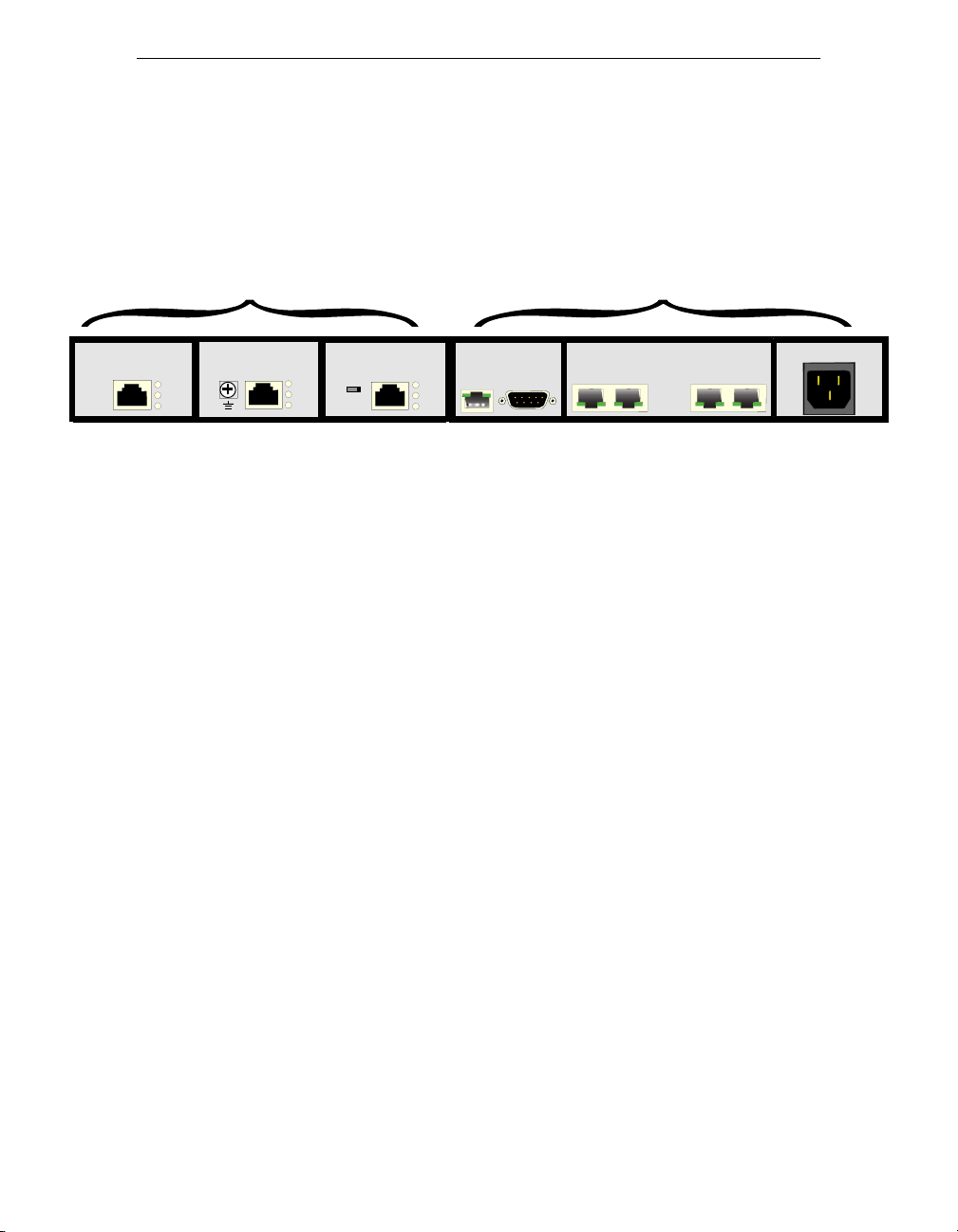
The 3000 Series has fixed modules and connectors, as well as slots for three
optional modules. Here is an example of the back panel of a 3000 Series.
Modular Fixed
DDS CSU/DSU
ALM
TST
LOS
Fixed Modules
The 3000 Series has two fixed connectors:
• 10BaseT Ethernet—to connect to your LAN
• Console—to connect to a PC for configuring and monitoring the 3000
Series
In addition, when you purchase your 3000 Series, you have the option of
having an analog voice module installed. You cannot remove or replace the
voice module.
Optional Modules
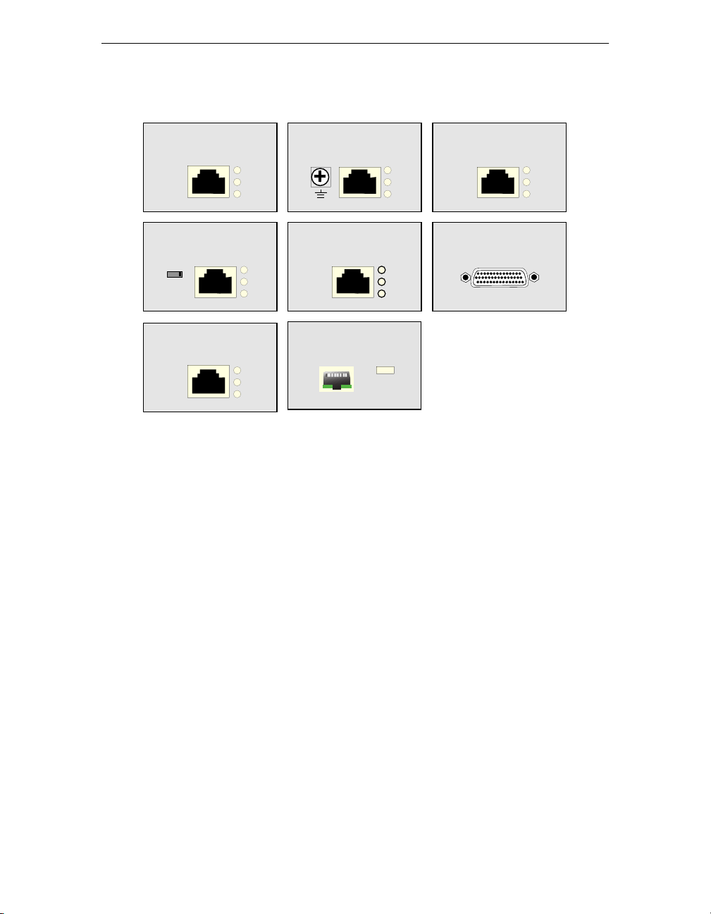
The following illustration shows the optional modules you can install in your
3000 Series.
• You can install ISDN modules in slot D3.
• You can Ethernet modules in slots D1 and D2.
• You can install the WAN, DDS, E1, T1, or SDSL modules in any slot.
E1
ALM
TST
LOS
ISDN S/T
01
ETH CONSOLE V1 V2 V3 V4
D
B1
B2
ANALOG VOICE
100-240VAC, 50-60Hz
1.6A
2 3000 Series User Guide
Page 17
DDS CSU/DSU
ALM
TST
LOS
E1
ALM
TST
LOS
T1 CSU/DSU
ALM
TST
LOS
ISDN S/T
01
SDSL
D
B1
B2
ALM
TST
LOS
ISDN U
ETH
WAN
D
B1
B2
PC HUB
LINKACT
3000 Series User Guide 3
Page 18

Introducing the 3000 Series Secure Gateway Router
Data and Voice Features
This section describes the data and voice networks that the 3000 Series
supports.
Data Capability
For routing data, the 3000 Series supports the following types of LANs and
WANs.
LAN
The 3000 Series comes with a fixed Ethernet port that provides a 10BaseT
Ethernet connection. It also offers an optional 10Base-T Ethernet module.
WAN
The 3000 Series supports the following types of WANs in its three modular
slots.
• DDS CSU/DSU module for 56 Kbps/64 Kbps digital services.
• T1/Fractional T1 CSU/DSU module for 56 Kbps to 1.536 Mbps digital
services.
• E1/Fractional E1 module for 64 Kbps to 2.048 Mbps digital services.
• ISDN U with two B and one D channels and with a built-in Network
Termination (NT1) device.
• ISDN S/T module with two B and one D channels.
• SDSL module for serial communication up to 2.048 Mbps.
• A standard WAN module (RS-232/V.35/X.21) that lets you connect to a
Frame Relay network or run the Point-to-Point Protocol (PPP) over either
a leased or a dialup telephone line.
4 3000 Series User Guide
Page 19

Voice Capability
You have the option of ordering a 3000 Series with two or four analog ports.
The voice ports offer the following features.
• Voice support for FXO (foreign exchange office), FXS (foreign exchange
service), or E&M (ear and mouth).
• H.323 voice encapsulation standard, including H.225.Ov2 and H.245v.4
standards.
• Switched Frame Transfer Mode (SFTM) technology, which lets you
switch voice and data traffic over the same lines.
Analog Voice
The analog voice module provides up to four ports that let you connect voice
and fax telephone equipment or analog PBX equipment to your 3000 Series.
3000 Series User Guide 5
Page 20

Introducing the 3000 Series Secure Gateway Router
6 3000 Series User Guide
Page 21

Chapter 2
Connecting Your 3000 Series
Secure Gateway Router
This chapter provides the steps for mounting your 3000 Series in a rack and
setting up your hardware connections. It has the following sections.
Before You Begin 8
What’s Next? 10
Connecting to an Ethernet 11
Connecting to an Analog Voice Network 11
Connecting to a DDS Network 13
Connecting to an E1 Network 13
Connecting to a T1 Network 14
Connecting to an SDSL Network 14
Connecting to an ISDN Line 15
Connecting to a WAN 18
3000 Series User Guide 7
Page 22

Connecting Your 3000 Series Secure Gateway Router
Connecting to a PC 22
Before You Begin
You can order your 3000 Series Secure Gateway Router either with the
modules you want already installed, or you can order the modules separately
and install them yourself. For instructions on installing the optional modules,
see Appendix B.
You have the option of mounting your 3000 Series in a rack. See Mounting
the 3000 Series in a Rack on page 9.
Depending on the modules installed in your particular 3000 Series, you need
the following cables. With the exception of a console cable to connect a PC to
your 3000 Series, these cables are not supplied.
To connect . . . You need . . .
Analog Voice
module
DDS module RJ-48S, 8-conductor straight-through cable.
Ethernet Ethernet 10BaseT (Unshielded Twisted Pair)
Fractional E1
module
Fractional T1
module
ISDN module RJ-45, 8-conductor straight-through cable.
SDSL module Cable with an RJ-48C connector (TIA 568B
The type of cable you use depends on the interface type
that the equipment you connect to supports.
Compliance with applicable regulations depends on the
use of shielded cables.
straight-through cable.
Cable with an RJ-48C connector (TIA 568B
compatible).
Cable with an RJ-48C connector (TIA 568B
compatible).
For ISDN S/T modules, you also need an external NT1
device and the appropriate cable to connect the NT1 to
the ISDN wall jack. The cable for this connection
depends on the NT1 device.
compatible).
8 3000 Series User Guide
Page 23
To connect . . . You need . . .
D1
D2
D3
OICE
V1
D1
D2
D3
ETH
V2
V3
V4
ALM
OK
PWR
To a PC or
terminal
Console null-modem cable with adapter to connect a
PC or terminal to your gateway router. (Supplied with
your 3000 Series.)
WAN module The appropriate serial WAN cable(s).
x
The 3000 Series supports only N
Networks WAN
cables. See Selecting a WAN Cable on page 18 for a
list of WAN cables.
Mounting the 3000 Series in a Rack
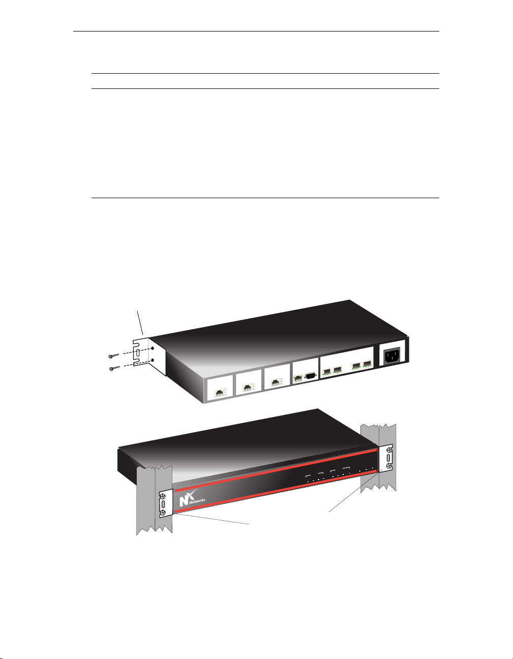
You can mount the 3000 Series in a rack. The 3000 Series comes with two
mounting brackets and four screws. You can attach the brackets to connect
either the front of the unit or the back of the unit to the rack.
Mounting Bracket
E
IC
O
V
2
V
1
V
E
L
O
S
N
O
C
H
T
D3
D2
L
S
D
S
U
S
/D
U
D1
S
C
T1
A
T
M
L
A
T
S
T
S
M
LO
L
T
S
S
LO
E
U
N
D
IS
LM
A
T
S
T
S
O
L
100-2
4
V
3
V
z
0H
-6
, 50
C
A
40V
.6A
1
PWR
OK
ALM
DATA
ETH
D3
D2
D1
VOICE
V4
V3
V2
V1
3000 Series
Mounting Brackets
Connected to Rack
3000 Series User Guide 9
Page 24

Connecting Your 3000 Series Secure Gateway Router
What’s Next?
The following sections show how to connect your gateway router to each type
of network.
To connect to . . . See page . . .
Analog Voice network
DDS network
E1 network
Ethernet
ISDN
SDSL network
T1 network
WA N
PC (Console)
11
13
13
11
15
14
14
18
22
10 3000 Series User Guide
Page 25
Connecting to an Ethernet
OICE
V1
D1
D2
D3
ETH
V2
V3
V4
ALM
OK
PWR
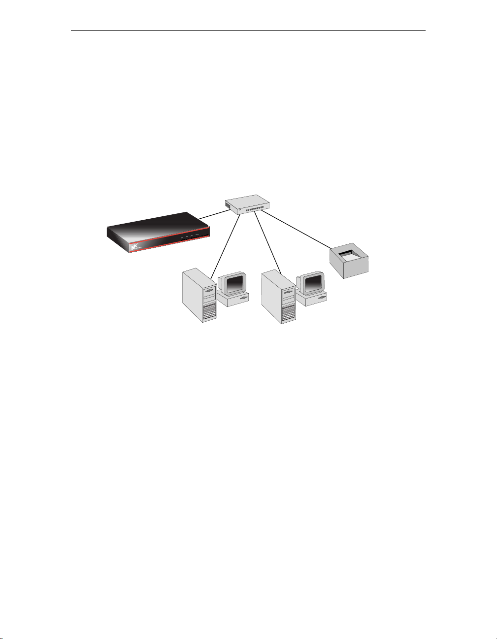
To connect your 3000 Series to an Ethernet network,
1. Connect one end of an Ethernet 10BaseT (UTP) straight-through cable to
the ETH connector in the 3000 Series fixed slot.
2. Connect the other end of the cable to an Ethernet 10BaseT hub.
Ethernet Hub
R
W
P
K
O
M
L
A
DATA
H
T
E
D3
2
D
E
1
D
IC
VO
4
V
3
V
2
V
1
V
3000 Series
3000 Series
Printer
PC
PC
Connecting to an Analog Voice Network
Note: You cannot connect the analog voice module directly to the external
network.
The type of cable you use depends on the interface type that the equipment
you connect to supports. For compliance with applicable regulations, you
need to use shielded cables.
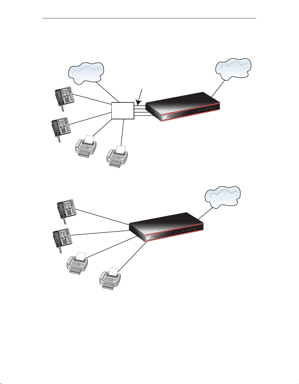
To connect your 3000 Series to your PBX or voice or fax telephone
equipment,
1. Connect one end of the cable to the RJ-45 connector on the 3000 Series.
2. Connect the other end of the cable to the PBX, telephone, or fax device.
3000 Series User Guide 11
Page 26
Connecting Your 3000 Series Secure Gateway Router
3000 Series
OICE
V1
D1
D2
D3
ETH
V2
V3
V4
ALM
OK
PWR
3000 Series
OICE
V1
D1
D2
D3
ETH
V2
V3
V4
ALM
OK
PWR
Telephone
Network
FXS
FXO or E&M
PBX
3000 Series
3000 Series
3000 Series
VO
V
1
V
3000 Series
P
K
O
M
L
A
DATA
H
T
E
3
D
2
D
E
1
C
D
I
VO
4
V
3
V
2
V
1
V
Internet
R
W
P
K
O
M
L
A
DATA
H
T
E
3
D
2
D
E
1
C
D
I
4
V
3
V
2
Internet
R
W
12 3000 Series User Guide
Page 27
Connecting to a DDS Network
OICE
V1
D1
D2
D3
ETH
V2
V3
V4
ALM
OK
PWR
3000 Series
OICE
V1
D1
D2
D3
ETH
V2
V3
V4
ALM
OK
PWR
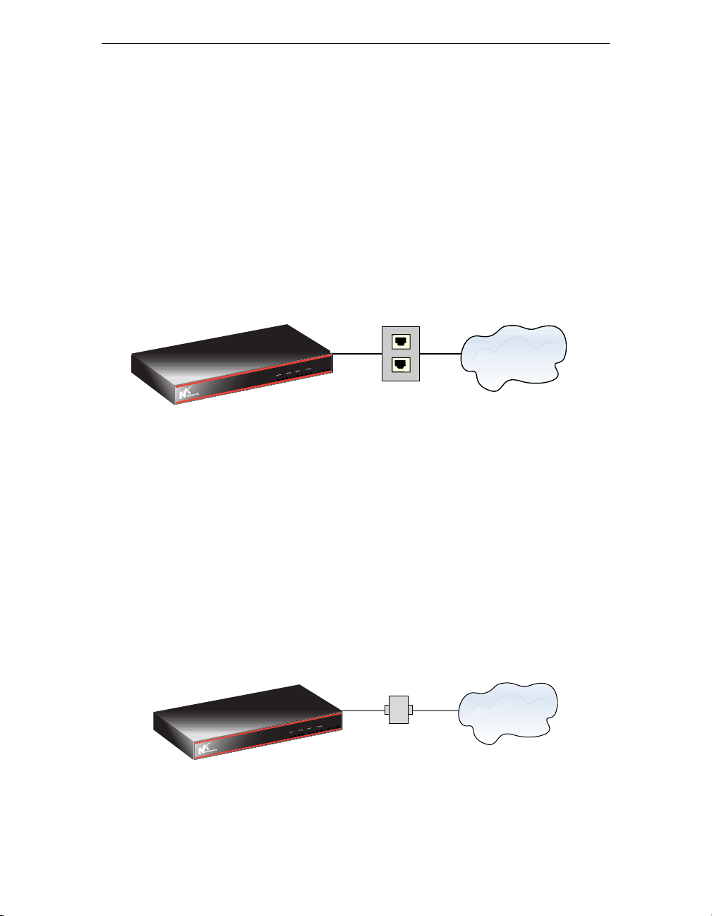
To connect to a leased-line DDS network,
1. Connect one end of the unshielded twisted pair (UTP) RJ-48S cable to the
CSU/DSU connector on the DDS CSU/DSU module.
2. Connect the other end of the cable to an RJ-48S network interface jack
provided by your service provider.
The following figure shows the connection between the DDS module and a
DDS network.
DDS
3000 Series
3000 Series
R
W
P
K
O
M
L
A
DATA
H
T
E
3
D
2
D
E
1
C
D
I
VO
4
V
3
V
2
V
1
V
RJ-48S
Jack
Connecting to an E1 Network
To connect to an E1 network,
1. Attach one end of a grounding wire to the GND (ground) on the E1
module and then attach the other end to a system ground. (Optional)
2. Connect one end of the unshielded twisted pair (UTP) RJ-48C cable to the
E1 connector on the E1 module.
3. Connect the other end of the cable to the service provider’s network
interface box.
E1
3000 Series
3000 Series
PWR
OK
ALM
DATA
ETH
D3
D2
D1
VOICE
V4
V3
V2
V1
Network
Interface
Box
3000 Series User Guide 13
Page 28
Connecting Your 3000 Series Secure Gateway Router
OICE
V1
D1
D2
D3
ETH
V2
V3
V4
ALM
OK
PWR
OICE
V1
D1
D2
D3
ETH
V2
V3
V4
ALM
OK
PWR
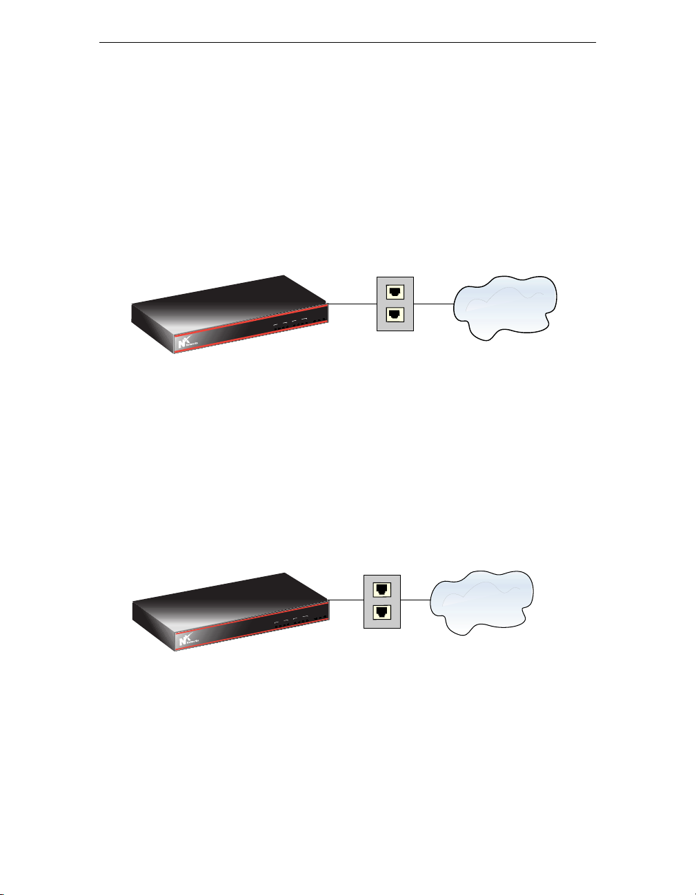
Connecting to a T1 Network
To connect to a T1 network,
1. Connect one end of the unshielded twisted pair (UTP) RJ-48C cable to the
T1 connector on the T1 DSU/CSU module.
2. Connect the other end of the cable to an RJ-48C network interface jack
provided by your service provider.
T1
3000 Series
3000 Series
R
W
P
K
O
M
L
A
DATA
H
T
E
3
D
2
D
E
1
C
D
I
VO
4
V
3
V
2
V
1
V
RJ-48C
Jack
Connecting to an SDSL Network
To connect to a Digital Subscriber Loop Access Multiplexor (DSLAM),
1. Connect one end of the unshielded twisted pair (UTP) RJ-48C cable to the
connector on the SDSL module.
2. Connect the other end of the cable to an RJ-48C network interface jack
provided by your service provider.
DSLAM
3000 Series
V
3000 Series
R
W
P
K
O
M
L
A
DATA
H
T
E
3
D
2
D
E
1
C
D
I
VO
4
V
3
V
2
V
1
RJ-45
Jack
14 3000 Series User Guide
Page 29
Connecting to an ISDN Line
OICE
V1
D1
D2
D3
ETH
V2
V3
V4
ALM
OK
PWR
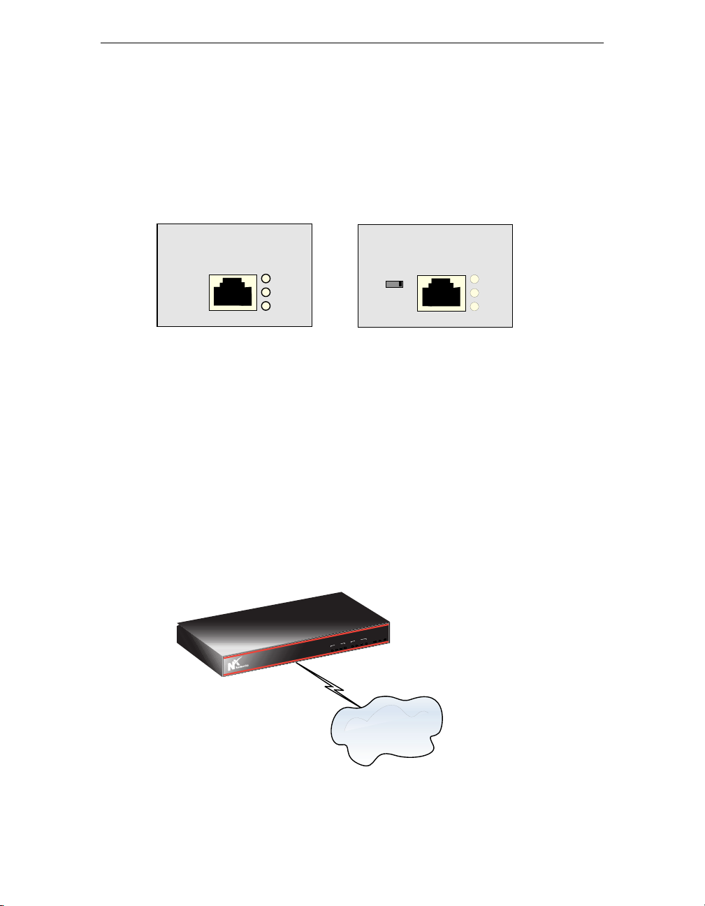
How you make the connection from your 3000 Series to an ISDN line
depends on whether your ISDN module is an ISDN U or ISDN S/T module.
Check the back panel of your gateway router to identify the ISDN module
installed.
ISDN U
D
B1
B2
ISDN S/T
01
D
B1
B2
ISDN U Module
Note: You can install this module only in slot 3 (D3).
The ISDN U module has a built-in Network Termination (NT1) device. The
NT1 provides for a direct connection to the ISDN network. When you use the
ISDN U module, you cannot use any other ISDN device on the ISDN line.
To connect your ISDN U module,
1. Connect one end of the RJ-45 ISDN cable (not supplied with your router)
to the RJ-45 ISDN connector on your ISDN U module.
2. Connect the other end of the ISDN cable directly into an ISDN wall jack.
R
W
P
K
O
M
L
A
DATA
H
T
E
3
D
2
D
E
1
C
D
I
VO
4
V
3
V
2
V
1
3000 Series
V
3000 Series
Internet or
Other WAN
3000 Series User Guide 15
Page 30

Connecting Your 3000 Series Secure Gateway Router
Caution
You can also use an RJ-11 cable with a regular
analog telephone to connect the 3000 Series to the
ISDN wall jack.
x
Networks discourages using an RJ-11 cable for
N
this purpose, however, because you may
inadvertently plug the 3000 Series into a normal
telephone jack rather than into an ISDN wall jack.
This can damage the 3000 Series.
ISDN S/T Module
Notes:
• You can install this module only in slot 3 (D3).
• You must connect to the ISDN network via a line isolation unit (NT1
device).
The S/T module does not have a built-in NT1 device. You must provide an
external NT1 device. A typical NT1 device looks like a small modem and has
S/T port(s) and a U interface on the back of it.
The ISDN S/T module can co-exist with other ISDN equipment using the
same ISDN line.
To connect your ISDN S/T module,
1. Connect one end of the RJ-45 ISDN cable (not supplied with your router)
to the RJ-45 ISDN connector on the ISDN S/T module.
2. Connect the other end of the ISDN cable to the S/T port on the NT1
device.
3. Set the S/T terminator switch on the ISDN module to the appropriate
position. See Setting the S/T Switch on page 17.
16 3000 Series User Guide
Page 31
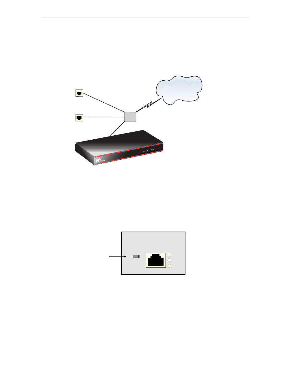
4. Connect one end of an ISDN cable to the NT1 U interface port and the
OICE
V1
D1
D2
D3
ETH
V2
V3
V4
ALM
OK
PWR
other end to the ISDN wall jack. The ISDN cable for this connection is
dependent on your NT1 device.
Telephone
Internet or
Other WAN
Fax
NTI
3000 Series
R
W
P
K
O
M
L
A
DATA
H
T
E
3
D
2
D
E
1
C
D
I
VO
4
V
3
V
2
V
1
V
3000 Series
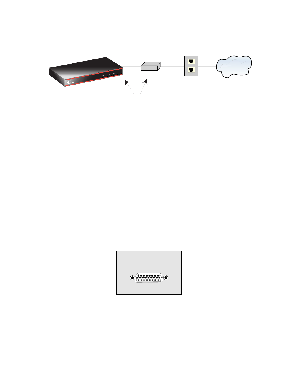
Setting the S/T Switch
There is an S/T switch on the ISDN S/T module. You can slide the switch to 0
or 1. Setting the switch to 0 means that no terminating resistor is in use.
Setting the switch to 1 means that the ISDN S/T module terminates the ISDN
cable with a 100-ohm resistor.
ISDN S/T
S/T Switch
01
D
B1
B2
For point-to-point connections (shown in the following figure), set the switch
to 1. For all other configurations, consult your NT1 manual for the proper
setting. In a point-to-point connection, there is one ISDN device on an ISDN
line.
3000 Series User Guide 17
Page 32
Connecting Your 3000 Series Secure Gateway Router
3000 Series
OICE
V1
D1
D2
D3
ETH
V2
V3
V4
ALM
OK
PWR
3000 Series
3000 Series
S/T
Interface
R
W
P
K
O
M
L
A
DATA
H
T
E
3
D
2
D
E
1
C
D
I
VO
4
V
3
V
2
V
1
V
100 Ohm Termination
NT1
U
Interface
Network
ISDN
Wall Jack
Connecting to a WAN
To connect your 3000 Series to the Internet or another WAN using the
standard WAN module, use Point-to-Point Protocol (PPP) over either a
dedicated (leased) or a dialup telephone line or use a Frame Relay network.
Selecting a WAN Cable
You must purchase the appropriate cable from a Nx Networks vendor. The
type of WAN cable you use depends on the interface type that the equipment
you connect to supports.
ISDN
To connect to a device that has a
• Data Communications Equipment (DCE) connector, use a Data Terminal
Equipment (DTE) cable.
• DTE connector, use a DCE cable.
WAN
18 3000 Series User Guide
Page 33
To be sure that you are using the proper cable to connect your WAN module,
OICE
V1
D1
D2
D3
ETH
V2
V3
V4
ALM
OK
PWR
check the part number on the cable with the information in the following
table.
To connect the standard WAN
module to . . .
Use cable
type . . .
Part Number
an external asynchronous modem. RS-232 DTE P4730-09
an external synchronous modem, a
modem eliminator, or a CSU/DSU.
(Whether you use RS-232, V.35, or X.21,
RS-232 DTE
V. 3 5 D T E
X.21 DTE
P4730-09
P4730-08
P4730-10
depends on which type of communication
the equipment you connect to supports.)
another router that has a DTE connector.
(In this case, you must set up the 3000
Series to provide clocking.)
RS-232 DCE
V. 3 5 D C E
X.21 DCE
P4730-12
P4730-11
P4730-13
(Whether you use RS-232, V.35, or X.21,
depends on which type of communication
the equipment you connect to supports.)
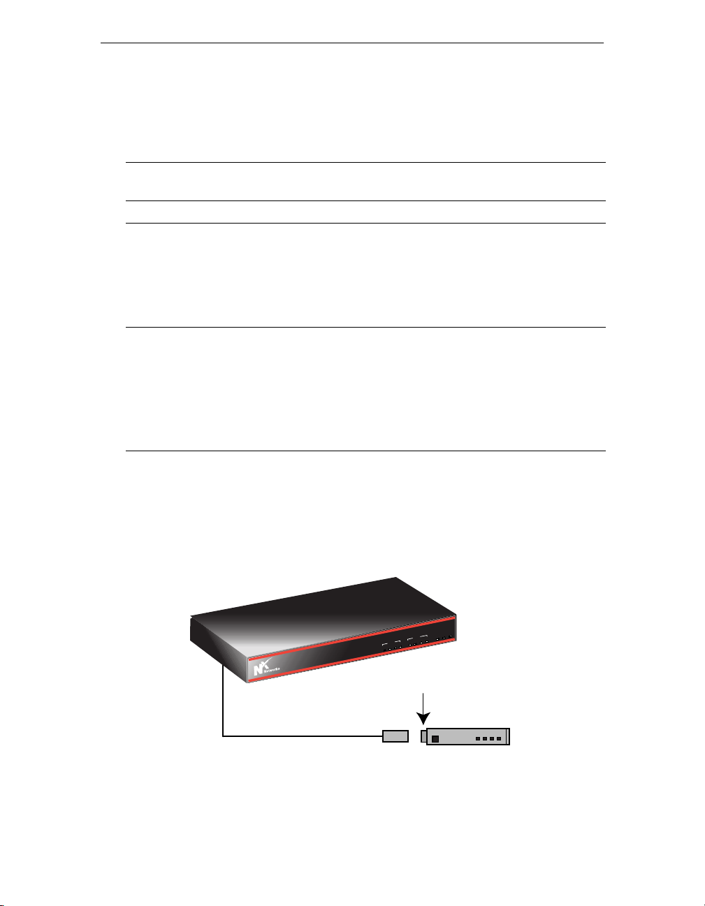
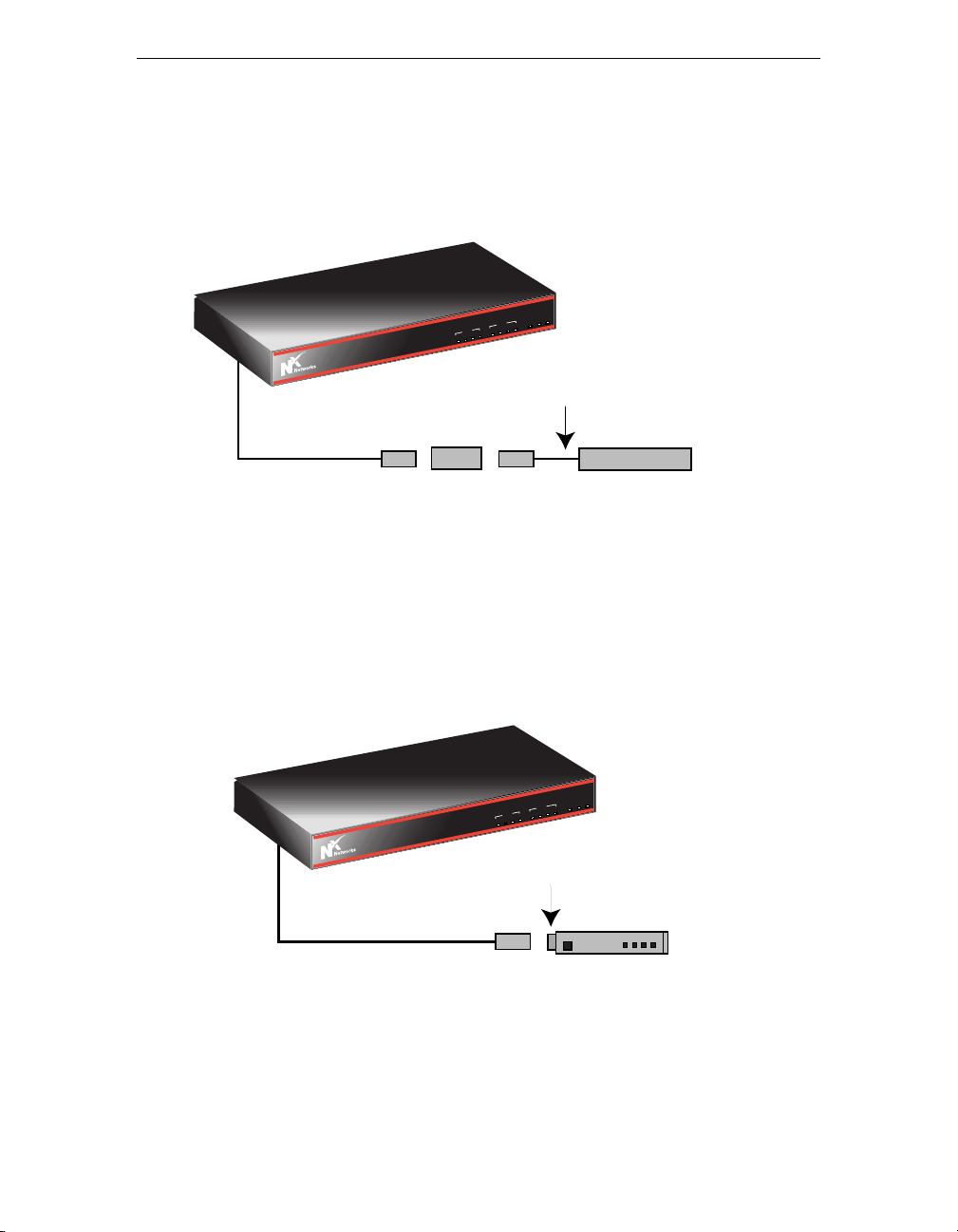
The following three figures show possible DTE/DCE connections.
This figure shows a DTE cable connection to a device with a DCE
connector.
3000 Series
R
W
P
K
O
M
L
A
DATA
H
T
E
3
D
2
D
E
1
C
D
I
VO
4
V
3
V
2
V
1
V
3000 Series
DCE Connector
DTE Interface
Cable
In this configuration, the CSU/DSU or modem provides
DTE
clocking. You can use V.35, RS-232, or X.21 cabling.
3000 Series User Guide 19
Page 34
Connecting Your 3000 Series Secure Gateway Router
OICE
V1
D1
D2
D3
ETH
V2
V3
V4
ALM
OK
PWR
3000 Series
OICE
V1
D1
D2
D3
ETH
V2
V3
V4
ALM
OK
PWR
This figure shows DTE cable connections to a device (modem
eliminator) with a DCE connector.
3000 Series
R
W
P
K
O
M
L
A
DATA
H
T
E
3
D
2
D
E
1
C
D
I
VO
4
V
3
V
2
V
1
3000 Series
DTE Interface
Cable
In this configuration, the modem eliminator provides
clocking. You can use V.35, RS-232, or X.21 cabling.
V
DTE Interface
Cable
Modem
Eliminator
This figure shows a DCE cable connection to a device with a DTE
connector.
3000 Series
R
W
P
K
O
M
L
A
DATA
H
T
E
3
D
2
D
E
1
C
D
I
VO
4
V
3
V
2
V
1
V
DTE Connector
DCE
3000 Series
DCE Interface
Cable
In this configuration, the router provides clocking.
You can use V.35, RS-232, or X.21 cabling.
20 3000 Series User Guide
Page 35
Connecting to a PPP WAN
OICE
V1
D1
D2
D3
ETH
V2
V3
V4
ALM
OK
PWR
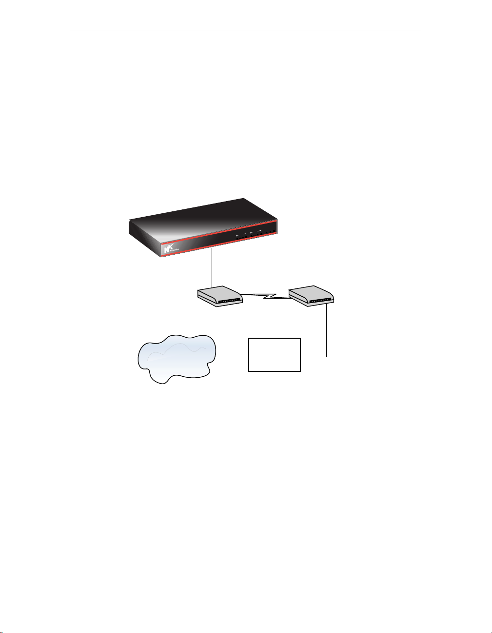
To connect the WAN module to a PPP WAN,
1. Connect the module to an external modem.
Note: The 3000 Series support both asynchronous and synchronous
modems.
2. Connect the modem to the telephone line with an RJ-11 cable.
3000 Series
R
W
P
K
O
M
L
A
DATA
H
T
E
3
D
2
D
E
1
D
IC
VO
4
V
3
V
2
V
1
3000 Series
V
PSTN
Modem
Modem
Internet or
Other WAN
Internet
Service
Provider
(PSTN = Public Switched Telephone Network)
Connecting to a Frame Relay WAN
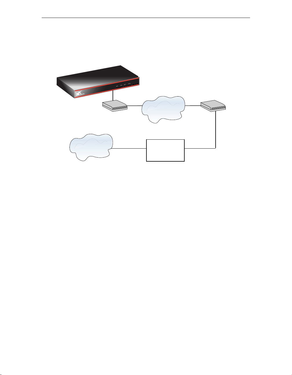
To connect the WAN module to a Frame Relay WAN,
1. Connect the module to an external Channel Service Unit/Digital Service
Unit (CSU/DSU).
You can purchase the appropriate cable from N
a WAN Cable on page 18.
Note: The 3000 Series works with any of the major CSU/DSU products
on the market.
x
Networks. See Selecting
3000 Series User Guide 21
Page 36
Connecting Your 3000 Series Secure Gateway Router
OICE
V1
D1
D2
D3
ETH
V2
V3
V4
ALM
OK
PWR
2. Connect the CSU/DSU to the Frame Relay switch.
3000 Series
R
W
P
K
O
M
L
A
DATA
H
T
E
3
D
2
D
E
1
C
D
I
VO
4
V
3
V
2
V
1
3000 Series
V
Frame
Relay
CSU/DSU
CSU/DSU
Internet or
Other WAN
Internet
Service
Provider
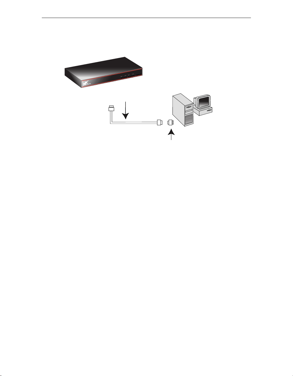
Connecting to a PC
To configure and monitor the 3000 Series through its console port, you can
connect a PC or terminal to the console port. (You can also configure and
monitor the router by connecting to its Ethernet port. See Configuring Your
3000 Series Secure Gateway Router on page 25.)
To connect a PC or terminal locally to the gateway router, use the 9-pin to 9pin null modem cable that comes with the 3000 Series and, if needed, the 9pin to 25-pin adapter. The following figure shows how to connect a PC or
terminal directly to the 3000 Series.
1. Connect one end of the null-modem cable to the Console connector on the
back panel of your gateway router.
2. Connect the other end of the cable to your PC.
22 3000 Series User Guide
Page 37
3000 Series
OICE
V1
D1
D2
D3
ETH
V2
V3
V4
ALM
OK
PWR
3000 Series
PWR
OK
ALM
DATA
ETH
D3
D2
D1
VOICE
V4
V3
V2
3000 Series
V1
9-pin to 9-pin Null
Modem Cable
PC
9-pin to 9-pin adapter
(Use if you need to connect
to a 25-pin connector on the PC.)
3000 Series User Guide 23
Page 38

Connecting Your 3000 Series Secure Gateway Router
24 3000 Series User Guide
Page 39

Chapter 3
Configuring Your 3000 Series
Secure Gateway Router
This chapter introduces the software tools available for configuring and
monitoring your 3000 Series. It includes the following topics.
Configuration Tools 26
Before Starting 27
Using QuickWeb 28
Using Quick Config and the Command Line Interface 29
3000 Series User Guide 25
Page 40

Configuring Your 3000 Series Secure Gateway Router
Configuration Tools
You receive your 3000 Series with software already installed. The actual
software installed depends on the software package that you purchased.
You can use one of the following tools to configure your gateway router:
• QuickWeb
QuickWeb is a software tool that lets you configure your router using a
Web browser. QuickWeb software resides on your router.
• Quick Config
A question and answer script that lets you set basic configuration
information. It is part of the Command Line Interface.
• Command Line Interface (CLI)
Provides full configuration capabilities that let you further customize your
router’s configuration.
Connecting to the 3000 Series
The 3000 Series comes with a preconfigured LAN IP address of 192.168.1.1
set to its fixed Ethernet port. If there is a Dynamic Host Configuration
Protocol (DHCP) server on your network, your router receives its IP address
dynamically from the server.
To configure your 3000 Series, you can
• Connect to the 3000 Series over your Ethernet network. You can then run
Telnet to IP address 192.168.1.1, which is the preconfigured address of
the fixed Ethernet port.
• Connect a PC to the 3000 Series console port. You can then connect to the
3000 Series using a terminal emulator. See Connecting to a PC on page
22.
26 3000 Series User Guide
Page 41

Before Starting
You also need certain information to configure your router. The following
worksheets, found in Appendix C on page 59, help to identify the basic
information you need for configuring your router.
Worksheet When needed?
IP Addressing
Dialup PPP
Frame Relay
ISDN
Always
When using PPP over your WAN connection
When using Frame Relay over your WAN connection
When using ISDN
3000 Series User Guide 27
Page 42

Configuring Your 3000 Series Secure Gateway Router
Using QuickWeb
You can use QuickWeb, the configuration tool that comes as part of your
router’s software, to configure your router.
To run QuickWeb . . .
1. Launch your World Wide Web browser.
x
N
Networks recommends that you use Internet Explorer 4.0 or later. (If
you are using Nescape Navigator, use version 4.0 or later.)
2. Enter the following in the Address (or Location) text box on your
browser. QuickWeb is case sensitive.
http://192.168.1.1/QuickWeb
192.168.1.1 is the default IP address of the 3000 Series fixed Ethernet
port. If you change the IP address of the Ethernet port, you will need to
use that new address to run QuickWeb in the future.
3. Follow the onscreen instructions to begin using QuickWeb.
If you need any information on any of the router’s parameters or options,
check the Help available with QuickWeb.
4. When you finish configuring your router, restart the router for the
configuration settings to take effect.
28 3000 Series User Guide
Page 43

Using Quick Config and the Command Line
Interface
You can use a PC connected to the router’s Console port to configure your
router. The PC must be running a terminal emulation program.
Using a Terminal Emulator
If you are running Windows 95 or 98 or Windows NT 4.0, you can use the
HyperTerminal application.
To set up HyperTerminal . . .
1. Click the Start button and select Programs, Accessories, and
HyperTerminal.
2. In the Connection description window, enter gt in the Name field and
select any icon to represent your terminal emulation.
3. In the Connect to dialog screen, in the Connect using field, select the
appropriate COM port to use.
4. In the COM1 Properties screen, select the following settings:
a. Bits per second: 9600
b. Data bits: 8
c. Parity: None
d. Stop bits: 1
e. Flow control: None
Using Quick Config
Quick Config presents a series of parameters for you to configure. You can
enter your own responses or accept the default settings.
To run Quick Config, follow these steps.
3000 Series User Guide 29
Page 44

Configuring Your 3000 Series Secure Gateway Router
1. At the * prompt, enter config to display the Config> prompt.
* config
Config>
2. Enter qconfig at the Config> prompt to begin Quick Config.
3. Proceed through the Quick Config questions to set (or change) the
parameters you need for your particular configuration.
To exit Quick Config, type r for restart at any prompt and follow the queries
until you type no and then q for quit.
Using the Command Line Interface
You can get extensive documentation on the Command Line Interface (CLI)
software that runs on the 3000 Series. This documentation is available on the
Online Library CD included in your 3000 Series package and also on the N
Networks Web site at www.nxnetworks.com.
x
Accessing the 3000 Series Documentation Set
On the Nx Networks Web site (www.nxnetworks.com),
1. Click Support Services.
2. Click User Documentation.
You now have access to an online version of this manual and also to the
complete set of software documentation.
30 3000 Series User Guide
Page 45

Chapter 4
Monitoring Your 3000 Series
Secure Gateway Router
You can monitor your 3000 Series by checking the status lights on the front
panel of your gateway router and also on the connectors and modules on the
back panel of your gateway router.
Front Panel 32
Analog Voice Module 35
DDS CSU/DSU Module 36
E1 Module 37
Ethernet Fixed Connector 38
Ethernet Module 39
ISDN Modules 40
SDSL Module 41
T1 CSU/DSU Module 42
3000 Series User Guide 31
Page 46
Monitoring Your 3000 Series Secure Gateway Router
OICE
V1
D1
D2
D3
ETH
V2
V3
V4
ALM
OK
PWR
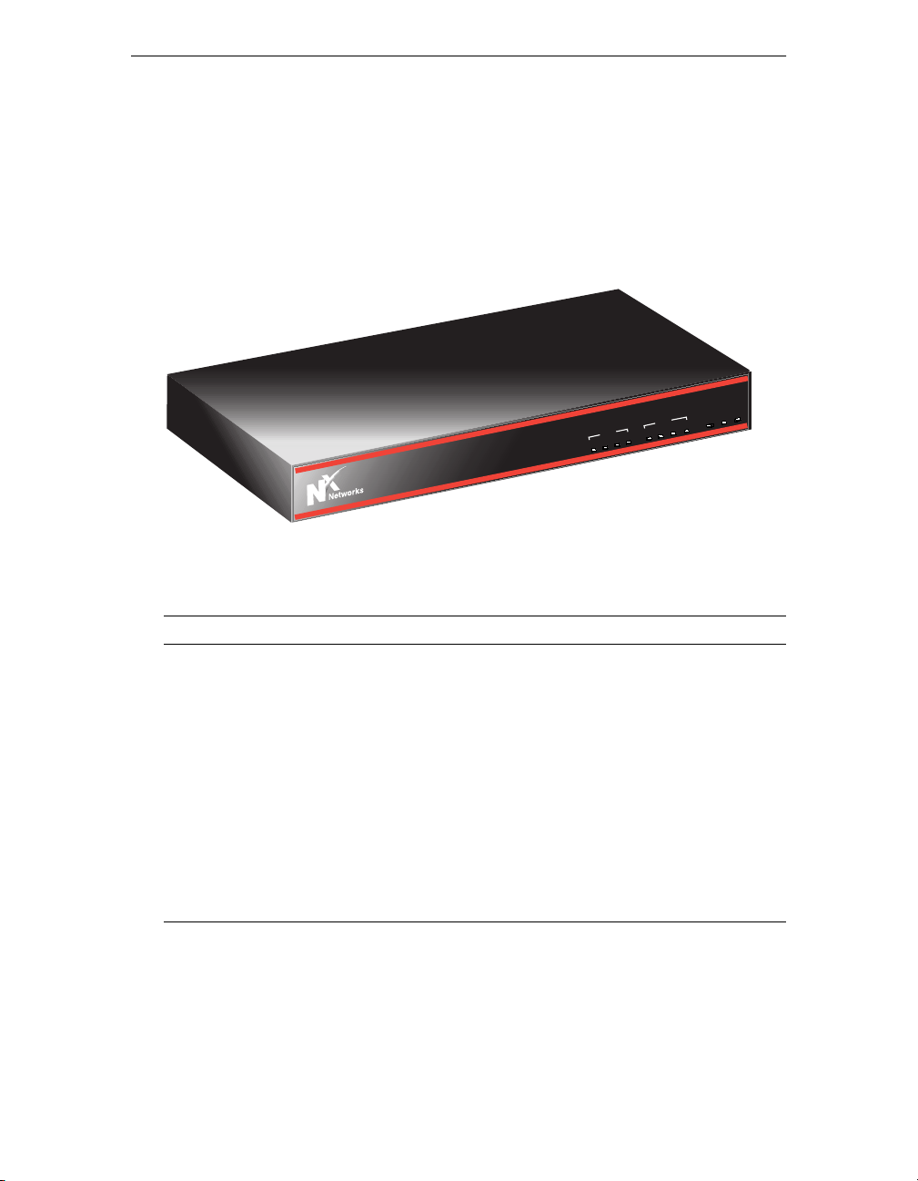
Front Panel
The status lights on the front of the 3000 Series indicate the current overall
status of the gateway router, as well as the status of the data ports and the
voice ports.
DATA
H
T
E
3
D
2
D
E
1
D
IC
VO
4
V
3
V
2
V
1
V
3000 Series
R
W
P
K
O
M
L
A
Light State Indicates . . .
PWR
(Power)
On
Blinking
Off
Power supply is operating within its
specifications.
Bad power supply.
Power is turned off, or power supply is
bad.
OK
On
3000 Series is running its operational
software.
Blinking
3000 Series is running its diagnostic or
startup (BOOT) software.
Off
32 3000 Series User Guide
3000 Series is not running.
Page 47

Light State Indicates . . .
ALM
On
The 3000 Series detected a
noncatastrophic hardware failure during
power up.
Off
Power is turned off or unit powered up
okay.
Data Ports
There are four lights on the front panel that indicate the status of the data
ports.
Light State Indicates . . .
ETH
(Ethernet)
D1
D2
D3
On
Blinking
Off
On
Blinking
Off
LAN connection to your local network is
up.
3000 Series is sending and receiving user
data on its LAN link.
Ethernet connection is not running.
Status of optional modules installed in
slots 1, 2, and 3.
Connection is up, and the 3000 Series is
sending maintenance data to the remote
device on its link.
3000 Series is sending and receiving user
data on its link.
Module installed in the particular slot is
not running, or no module is installed.
3000 Series User Guide 33
Page 48

Monitoring Your 3000 Series Secure Gateway Router
Voice Ports
There are four lights on the front panel that indicate the status of the voice
ports. Analog voice modules can have either two or four ports. Lights V1 and
V2 apply to the two-port model. Lights V1, V2, V3, V4 apply to the four-port
model.
Light State Indicates . . .
V1, V2,
V3, or V4
On
Off
Call is active
Call is not active
34 3000 Series User Guide
Page 49
Analog Voice Module
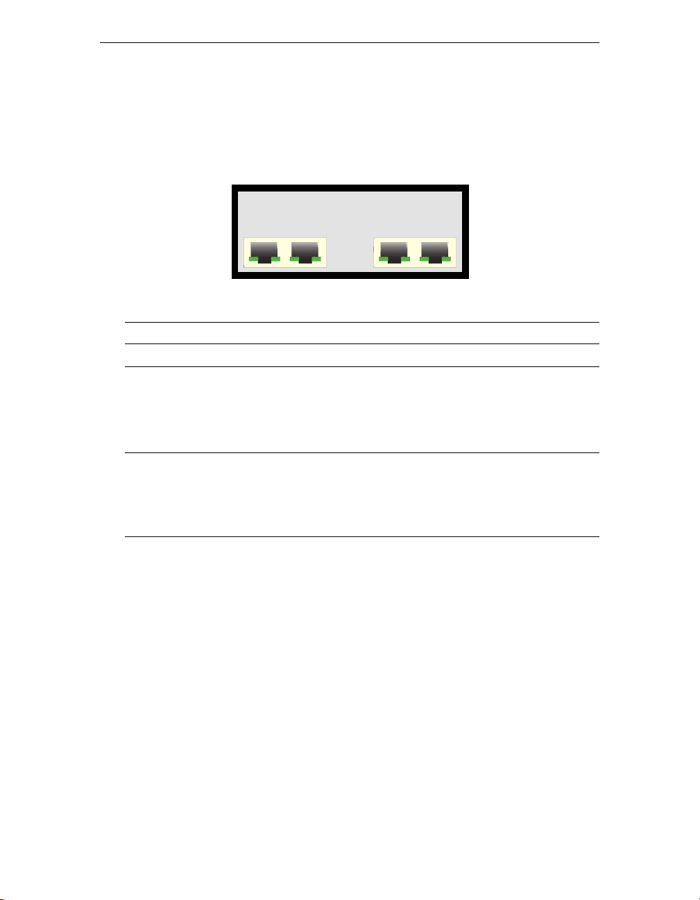
Each port of the fixed Analog Voice module has two status lights.
ANALOG VOICE
V1 V2 V3 V4
Light State Indicates . . .
Off
Green
Red
On
Slow Blink
Fast Blink
On
Blinking
Channel is not configured
Channel is idle
Call is active
Call is being set up (seizure inbound or
outbound)
Channel busied out (outbound seizure to
block incoming calls)
No PBX response (no inbound response to
outbound seizure)
3000 Series User Guide 35
Page 50
Monitoring Your 3000 Series Secure Gateway Router
DDS CSU/DSU Module
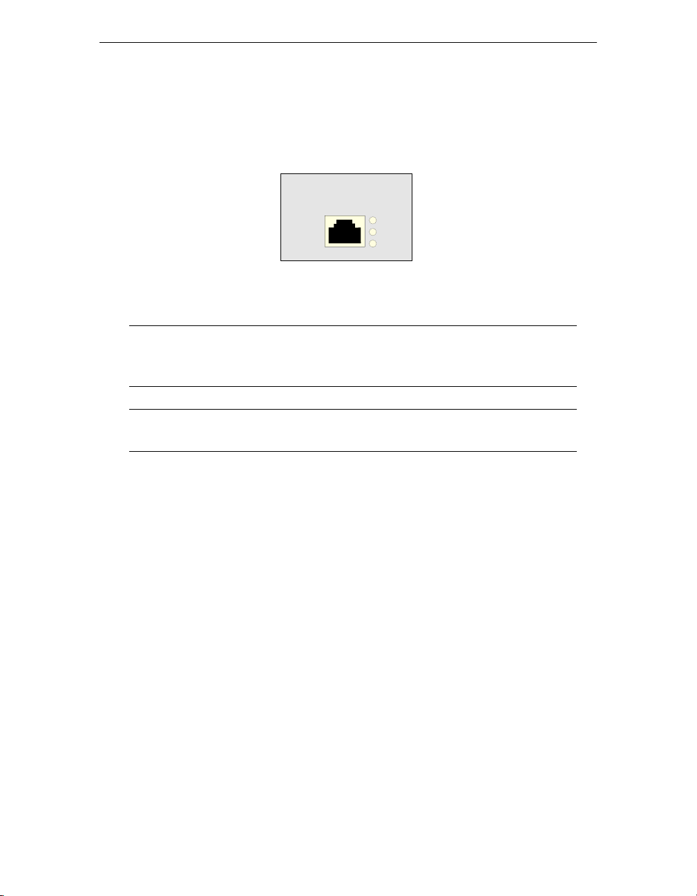
This module has three amber status lights.
DDS CSU/DSU
Light Indicates . . .
ALM
TST
LOS
Alarm condition indicating the loss of loop current, bipolar violations, loss of signal, out of service/out of
sync, out of frame, and unmatched control code.
Module is in loopback test mode.
Loss of signal indicating that the module is unable to
sync to the incoming data stream.
ALM
TST
LOS
36 3000 Series User Guide
Page 51
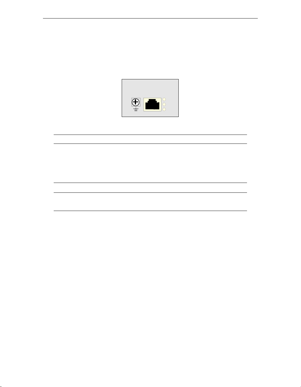
E1 Module
This module has three amber status lights.
Light Indicates . . .
ALM
TST
LOS
Alarm condition indicating the following:
• Alarm Indicator Signal (AIS)
• Remote Alarm Indicator (RAI)
• Loss of Carrier, Loss of Signal
Module is in loopback test mode.
Loss of sync indicating that the module is unable to
sync to the incoming data stream.
E1
ALM
TST
LOS
3000 Series User Guide 37
Page 52
Monitoring Your 3000 Series Secure Gateway Router
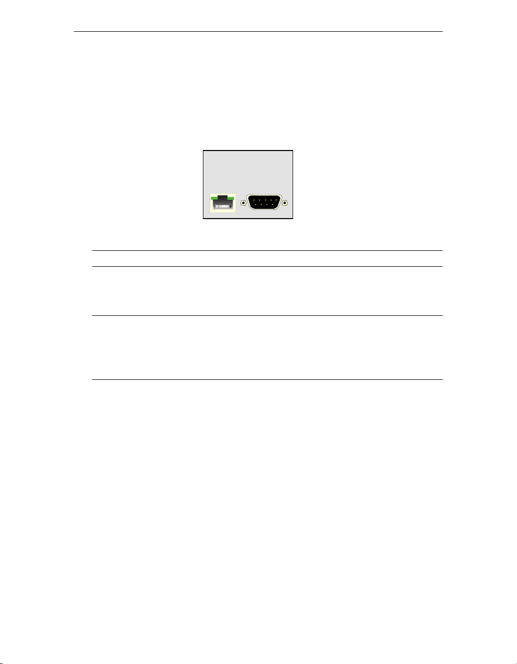
Ethernet Fixed Connector
The fixed Ethernet connector has two status lights. The left one is for link
status, and the right one is for traffic activity status.
ETH CONSOLE
Light State Indicates . . .
Left (Link
Status)
Right
(Activity
Status)
On
Blinking
Off
On
Blinking
Off
Ethernet connection is established.
N/A
No Ethernet connection established.
N/A
Traffic is being sent or received over the
Ethernet connection.
N/A
38 3000 Series User Guide
Page 53
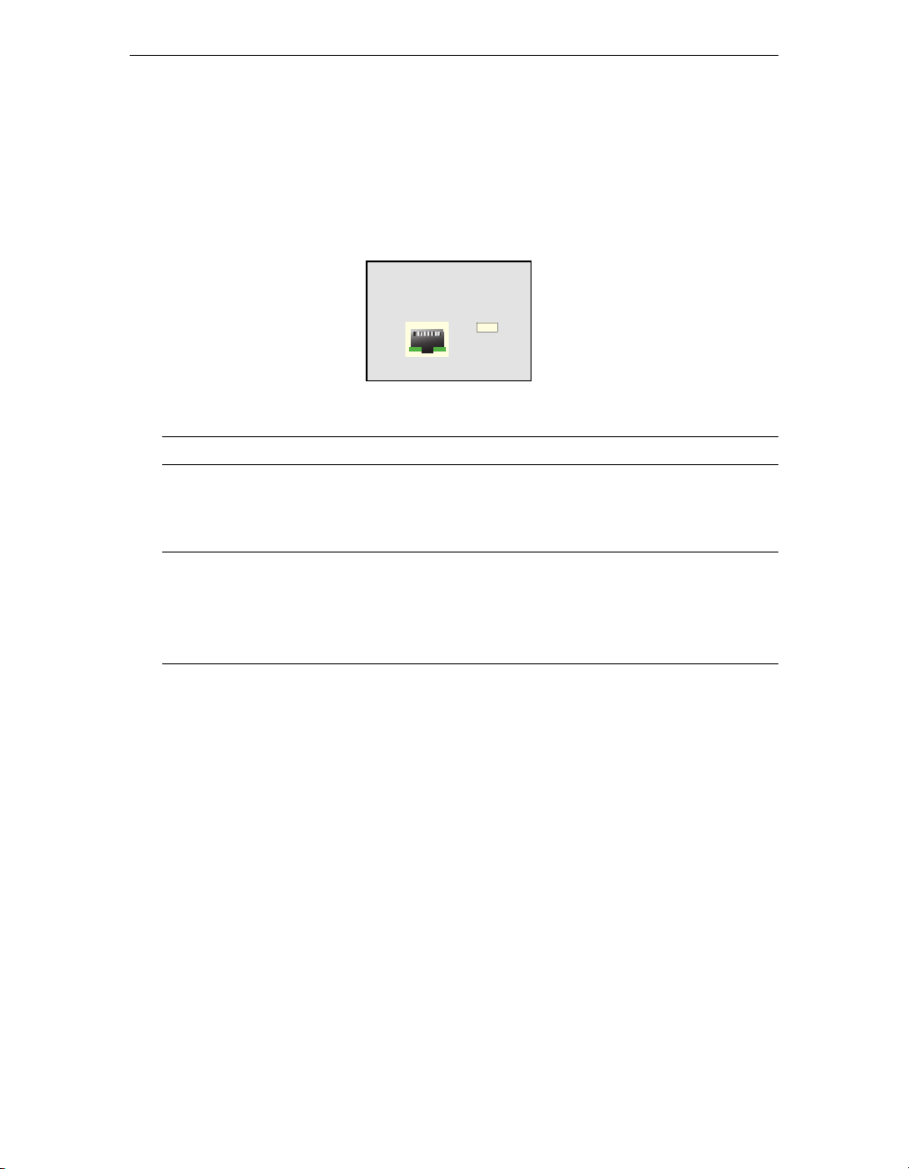
Ethernet Module
The Ethernet module has two status lights, one for link status and one for
traffic activity status.
ETH
PC HUB
LINKACT
Light State Indicates . . .
LNK (Link
Status)
ACT (Activity
Status)
On
Blinking
Off
On
Blinking
Off
Ethernet connection is established.
N/A
No Ethernet connection established.
N/A
Traffic is being sent or received over the
Ethernet connection.
N/A
3000 Series User Guide 39
Page 54
Monitoring Your 3000 Series Secure Gateway Router
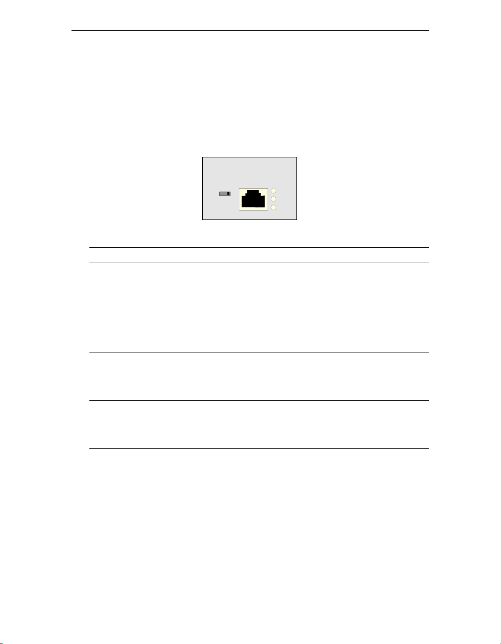
ISDN Modules
There are three green status lights on the ISDN U and S/T modules. These
lights indicate the ISDN BRI status of the two B and one D channels. Both B
and D channel lights go off when you restart the gateway router.
ISDN S/T
01
Light State Indicates . . .
D
On
ISDN S/T module is linked to the
D
B1
B2
telephone company.
Blinking
Off
Traffic is on the D channel.
ISDN S/T module is not linked to the
telephone company. This is an error in
North America but okay in Europe.
B1
B2
On
Blinking
Off
On
Blinking
Off
Call established on the B1 channel.
Traffic is on the B1 channel.
B1 channel is not in use or is idle.
Call established on the B2 channel.
Traffic is on the B2 channel.
B2 channel is not in use or is idle.
40 3000 Series User Guide
Page 55
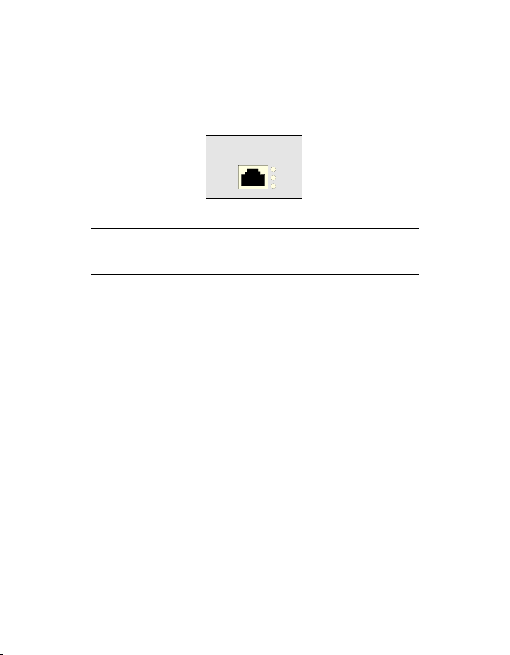
SDSL Module
This module has three amber status lights.
Light Indicates . . .
ALM
TST
LOS
Alarm condition indicating a loss of communication
between the SDSL module and the host processor.
Module is in loopback test mode.
Loss of sync indicating that the module is not activated
with the DSLAM (Digital Subscriber Loop Access
Multiplexor).
SDSL
ALM
TST
LOS
3000 Series User Guide 41
Page 56
Monitoring Your 3000 Series Secure Gateway Router
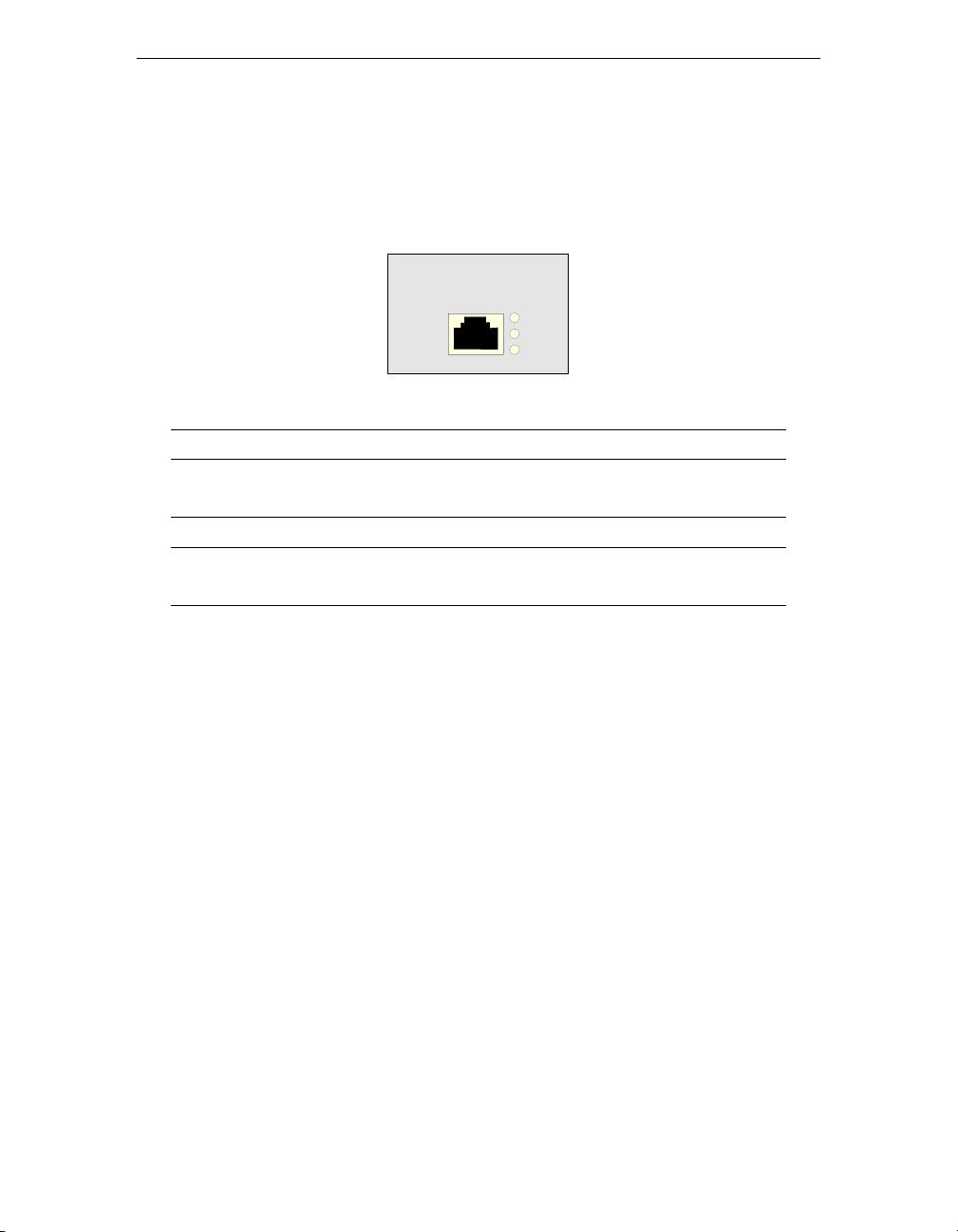
T1 CSU/DSU Module
This module has three amber status lights.
T1 CSU/DSU
Light Indicates . . .
ALM
TST
LOS
Alarm condition indicating standard blue, yellow, or
red alarm conditions.
Module is in loopback test mode.
Loss of sync indicating that the module is unable to
sync to the incoming data stream.
ALM
TST
LOS
42 3000 Series User Guide
Page 57

Appendix A
Specifications
This appendix provides the specifications for the 3000 Series Secure Gateway
Router and each of its modules.
3000 Series Secure Gateway Router Specifications 44
Analog Voice Module Specifications 45
DDS CSU/DSU Module Specifications 46
E1 Module Specifications 46
Ethernet Module Specifications 47
ISDN Module Specifications 47
SDSL Module Specifications 48
T1 CSU/DSU Module Specifications 49
WAN Module Specifications 49
3000 Series User Guide 43
Page 58

3000 Series Secure Gateway Router
Specifications
Specifications
Processor
Memory
DRAM
Flash
VPN
Input/Output Interfaces
Dimensions
Weight
Power
Operating Temperature
Relative Humidity
Heat Dissipation
MC 68EN360, 33 MHz
8 MB (expandable to 24, 40, or 72 MB)
8 MB
Optional hardware assist for data
encryption, authentication, and
compression
Console, RS-232 async
Ethernet 10BaseT
3 modular slots for data routing
Optional voice interface with either 2- or 4port analog
17.25 x 10 x 1.75 inches
10 lbs
100-240 VAC
50-60 Hz
1.4A MAX
41-105 degrees F
5-41 degrees C
8-80%
60 Watts, maximum
205 BTUs
44 3000 Series User Guide
Page 59

Agency Approvals
EMI— FCC Part 15 Class A;
CISPR 22 Class A; EN55022
Telecom— FCC Part 68, CS03, CTR2,
I-CTR3, CTR 12/A1, CTR13
Safety— UL 1950, CSA 22.2, TS.001,
AS/NZS3260, EN60950 CB
scheme for all countries
Immunity—IEC 801-2, 801-3, 801-4
Analog Voice Module Specifications
The following table lists the specifications for the analog voice module.
Interface Types • Two-wire FXS loop/start
• Two-wire FXO loop/ground start and two-wire
FXS loop/start
• Two-wire FXO loop/ground start
• Two- or four-wire E & M type I, II, and V
Dialing
Co-processor
Signalling
Indicator
DTMF or pulse (10 or 20 pps)
MPC850, 50 MHz
Wink start, delay dial, immediate start, hoot and holler,
and phone
One multicolored status LED
3000 Series User Guide 45
Page 60

Specifications
DDS CSU/DSU Module Specifications
The following table lists the specifications for the DDS CSU/DSU module.
Speed
Protocol
Connector
Indicators
Diagnostics
56 or 64 Kbps, primary channel
Sync, full duplex
RJ-48S
Alarm, Test Mode, Loss of Synchronization
CSU loopback, DSU non-latching loopback
(except 64 Kbps mode)
Clocking
Line Coding
FIC
SOC
Internal, Network
AMI, B8ZS
04DUS-56
6.0N
E1 Module Specifications
The following table lists the specifications for the E1 module.
Speed
Data Rate
Impedance
Connector
Indicators
Diagnostics
Clocking
Line Coding
Line Framing
2.048 Mbps
N x 64 Kbps up to 2.048 Mbps
120 ohm
RJ-48C
Alarm, Test Mode, Loss of Synchronization
Local, remote, and V.54 loopbacks
Internal, Network
HBD3
G.704, Structured & Unstructured
46 3000 Series User Guide
Page 61

Ethernet Module Specifications
The following table lists the specifications for Ethernet module.
Interface
Connector
Indicators
IEEE 802.3, 10BaseT
With signal crossover switch
RJ-45
Activity, Link status
ISDN Module Specifications
ISDN U
The following table lists the specifications for the ISDN U module.
Standards
Data Rate
Data Structure
Bit Rate
Connector
Indicators
Line Coding
FIC
SOC
ANSI T1.601
144 Kbps
2B + D
160 Kbps
RJ-49C
D Channel Status, (2) B Channel Status
2B1Q
02IS5
6.0N
3000 Series User Guide 47
Page 62

ISDN S/T
The following table lists the specifications for the ISDN S/T module.
Specifications
Standards
Data Rate
Data Structure
Bit Rate
Connector
Indicators
Line Coding
CCITT I.430
144 Kbps
2B + D
192 Kbps
RJ-61x, 2-pair conductor
D Channel Status, (2) B Channel Status
Pseudo-tenary
SDSL Module Specifications
The following table lists the specifications for the SDSL module.
Line Speed
Interface
Connector
Indicators
Signalling
Impedance
Diagnostics
144 Kbps to 2.320 Mbps
Single pair
RJ-48C
Alarm, Test Mode, Loss of Synchronization
2B1Q
135 ohm
Local and remote loopback
48 3000 Series User Guide
Page 63

T1 CSU/DSU Module Specifications
The following table lists the specifications for the T1 CSU/DSU module.
Speed
Data Rate
Impedance
Connector
Indicators
Diagnostics
Clocking
Line Coding
Line Framing
Transmit LBO
FIC
SOC
1.544 Mbps
N x 56 Kbps, N x 64 Kbps up to 1.536 Mbps
100 ohm
RJ-48C
Alarm, Test Mode, Loss of Sync
Local, remote, and V.54 loopbacks
Internal, Network
B8ZS
Extended Super Frame (ESP)
0 to -22dB
04DU9-BN,DN,1KN,1SN
6.0N
WAN Module Specifications
The following table lists the specifications for the WAN module.
WAN Speed
Interfaces
Connector
4.8 Kbps to 2.048 Mbps
V.35, RS232/V.24, X.21 (DTE and DCE)
DB 44
Use the appropriate external WAN cable. See Selecting
a WAN Cable on page 18
3000 Series User Guide 49
Page 64

Specifications
50 3000 Series User Guide
Page 65

Appendix B
Installing Modules and SIMMs
This appendix provides the procedures for installing optional modules in the
3000 Series Secure Gateway Router and for installing and removing a SIMM.
Caution
Before following the procedures in this appendix, see
the Safety Information on page v.
Installing a Module 52
Installing a SIMM 56
Removing a SIMM 57
3000 Series User Guide 51
Page 66

Installing Modules and SIMMs
Installing a Module
The procedure for installing a module in a 3000 Series is basically the same
for all the modules.
To install a module . . .
1. Turn off power to your 3000 Series.
2. Disconnect all network connections, including connections to the
telephone system.
3. Remove the cover by unscrewing the two screws on each side of the unit
and the three screws on the underside of the unit’s chassis and lifting off
the cover.
4. Remove the screws from the standoffs of the slot that you want to use.
5. Remove the module retaining bar by removing the three fastening screws.
6. Place the module in the slot that you want.
Notes:
• You can install the ISDN modules only in slot 3. You can install all
other modules in any of the three configurable slots.
• When you install an ISDN, SDSL, DDS, T1, or E1 module, do not
connect the telephone line until you have installed the module itself.
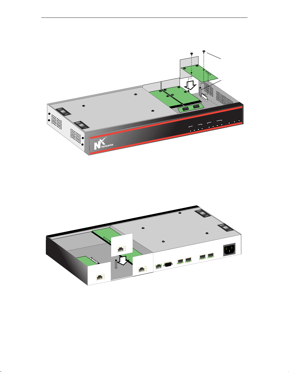
a. Line up the module with its two screw holes directly over the two
standoffs.
52 3000 Series User Guide
Page 67
OICE
V1
D1
D2
D3
ETH
V2
V3
V4
ALM
OK
PWR
Screw
D1
Standoff
R
PW
K
O
M
L
A
DATA
H
T
E
3
D
2
D
E
1
D
IC
VO
4
V
3
V
2
V
1
V
3000 Series
b. Press the module into place so that the connector on its underside sits
firmly in the connector on the motherboard. Be sure that you have
made a firm connection.
L
S
D
S
ALM
TST
LOS
LE
O
S
N
O
C
H
T
E
U
N
D
IS
U
S
/D
1
U
D
S
C
1
T
ALM
TST
LOS
ALM
TST
LOS
E
IC
O
V
2
V
1
V
4
V
3
V
100-240V
C
A
1.6A
z
, 50-60H
3000 Series User Guide 53
Page 68
3000 Series
OICE
V1
D1
D2
D3
ETH
V2
V3
V4
ALM
OK
PWR
OICE
V1
D1
D2
D3
ETH
V2
V3
V4
ALM
OK
PWR
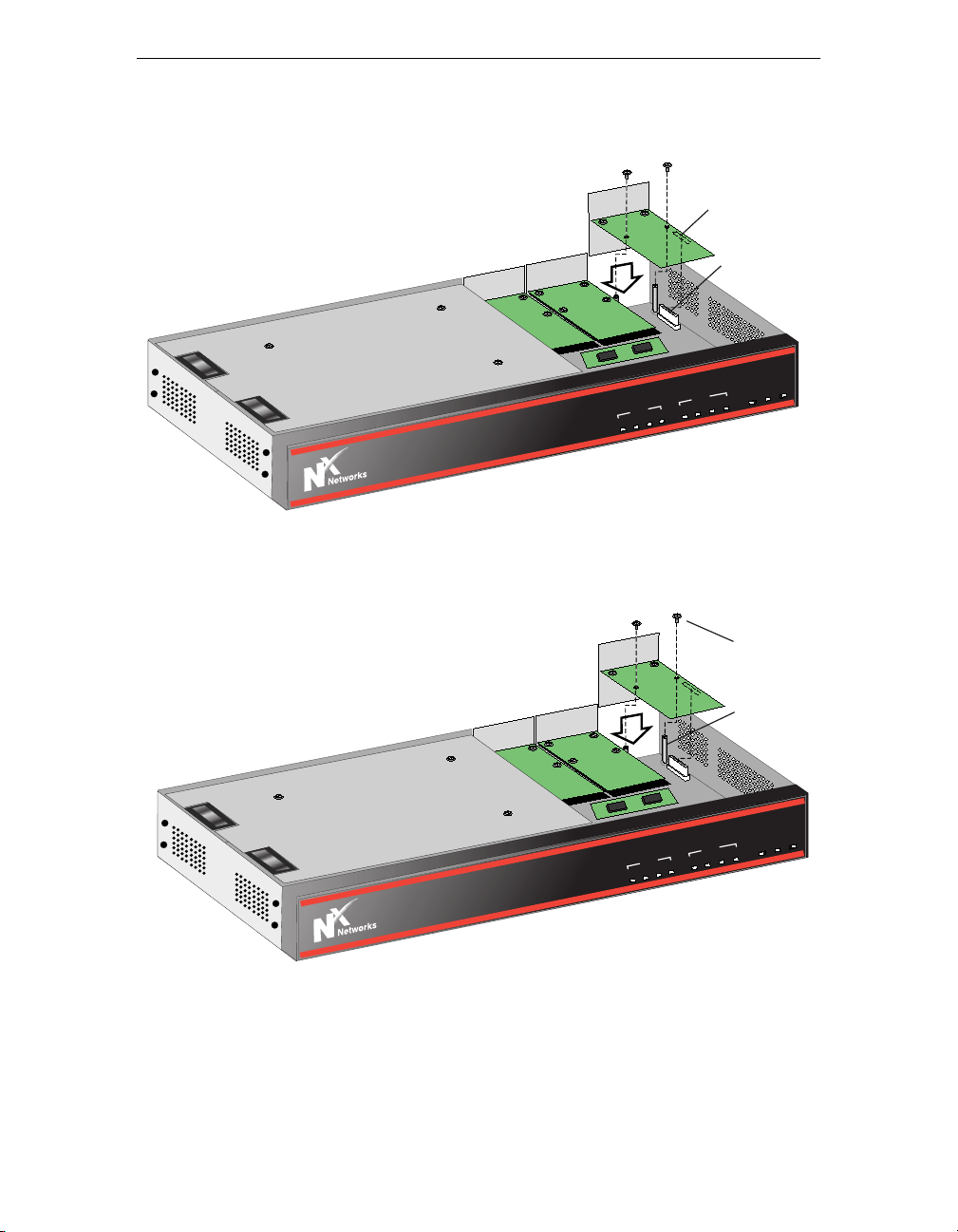
c. Screw the module to the two standoffs.
Installing Modules and SIMMs
Connector
on Module
Connector on
Motherboard
R
PW
K
O
M
L
A
DATA
H
T
E
3
D
2
D
E
1
D
IC
VO
4
V
3
V
2
V
1
V
DATA
2
D
E
1
D
IC
VO
4
V
3
V
2
V
1
V
3000 Series
d. Re-install the module retaining bar with its three retaining screws.
3
D
Screw
Standoff
H
T
E
R
W
P
K
O
M
L
A
54 3000 Series User Guide
Page 69

Caution
If you have a slot in your 3000 Series that does not
have a module installed in it, be sure to install a blank
slot cover in each open slot to ensure proper airflow
inside the chassis.
7. Replace the cover.
Be careful to line up the motherboard’s screw holes with the chassis’
screw holes.
3000 Series User Guide 55
Page 70
Installing Modules and SIMMs
OICE
V1
D1
D2
D3
ETH
V2
V3
V4
ALM
OK
PWR
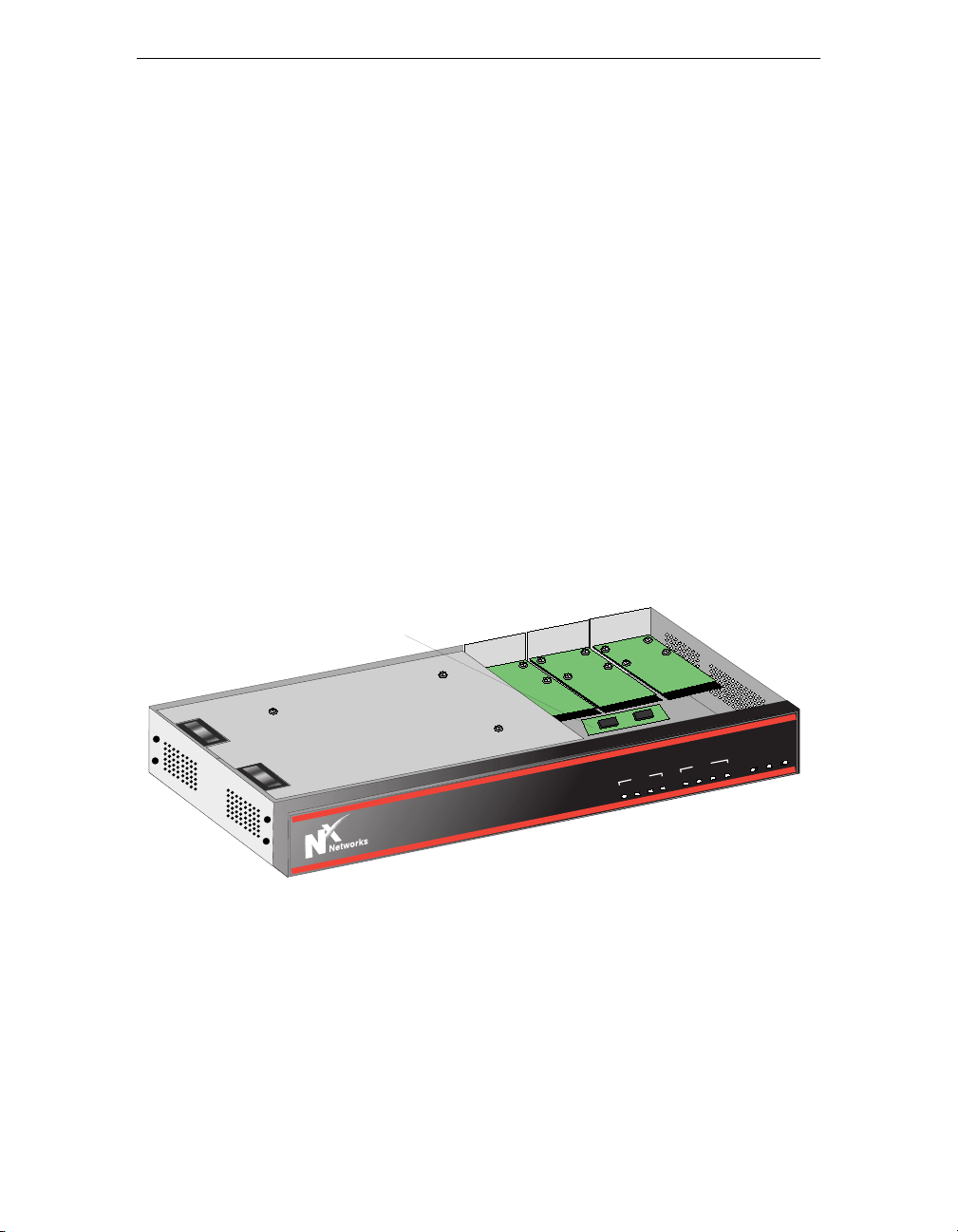
Installing a SIMM
You can upgrade your 3000 Series memory (DRAM) to 24, 40, or 72 MB by
installing a single in-line memory module (SIMM).
Note: To be sure that you have the appropriate SIMM for upgrading your
3000 Series memory, contact N
1. Turn off power to your 3000 Series.
2. Disconnect all network connections, including connections to the
telephone system.
3. Remove the cover by unscrewing the two screws on each side of the unit
and the three screws on the underside of the unit’s chassis and lifting off
the cover.
4. Seat the SIMM securely into place. Be careful to press the SIMM firmly
into place.
x
Networks.
SIMM
R
W
P
K
O
M
L
A
DATA
H
T
E
3
D
2
D
E
1
D
IC
VO
4
V
3
V
2
V
1
V
3000 Series
5. Press the SIMM back (toward the center of the motherboard) so that it sits
at an angle in its slot.
6. Replace the cover.
Be careful to line up the motherboard’s screw holes with the chassis’
screw holes.
56 3000 Series User Guide
Page 71

Removing a SIMM
To remove a single in-line memory module (SIMM) . . .
1. Turn off power to your 3000 Series.
2. Disconnect all network connections, including connections to the
telephone system.
3. Remove the cover by unscrewing the two screws on each side of the unit
and the three screws on the underside of the unit’s chassis and lifting off
the cover.
4. Press the detent tabs away from the center line and move the SIMM into
an upright position.
5. Remove the SIMM from its slot.
6. Install the new SIMM. See Installing a SIMM.
7. Replace the cover.
Be careful to line up the motherboard’s screw holes with the chassis’
screw holes.
3000 Series User Guide 57
Page 72

Installing Modules and SIMMs
58 3000 Series User Guide
Page 73

Appendix C
Worksheets
This appendix contains the following worksheets to help you in your initial
configuration of your 3000 Series Secure Gateway Router. Use the
worksheet(s) appropriate for your gateway router’s configuration.
IP Addressing 60
Dialup PPP 62
Frame Relay 63
ISDN 65
3000 Series User Guide 59
Page 74

Worksheets
IP Addressing
You need the following IP addressing information for all 3000 Series gateway
routers.
What is the IP address for your 3000 Series
Ethernet interface?
This address must be unique on the Ethernet.
What is the IP subnet mask for your 3000
Series Ethernet interface?
What are the IP addresses and subnet masks
of the WAN interfaces?
In place of an assigned IP address, you can
use unnumbered IP or dynamic IP
addressing.
In the command line interface, to set up
• unnumbered IP, set the IP address of
the WAN to 0.0.0.n, where n is the
number of the WAN interface, and
set the subnet mask to 0.0.0.0.
• dynamic IP addressing, set the IP
address of the WAN to 0.0.0.n
where n is the number of the WAN
interface, and set the subnet mask of
the WAN to 255.255.255.0.
______.______.______.______
______.______.______.______
IP Address ____.____.____.___
Mask____.____.____.____
IP Address ____.____.____.___
Mask ____.____.____.____
IP Address ____.____.____.___
Mask____.____.____.____
IP Address ____.____.____.___
Mask ____.____.____.____
60 3000 Series User Guide
Page 75

IP Addressing, continued
I am using (choose at least one)
Notes:
• If you are using a default gateway
that is connected to the 3000 Series
over the WAN device, and you are
using unnumbered IP, set the
default gateway to 0.0.0.1.
• If you are using static routes, you
need the destination network
address, its subnet mask, the IP
address of the next hop router, and
the number of hops to that router
(gateway).
• Not all versions of N
x
Networks
software support OSPF.
(a) _____ RIP
(b) _____ Default gateway of
_____._____._____._____
(c) _____ Static route to
____.____.____.____
Address mask
____.____.____.____
Via gateway
____.____.____.____
Number of hops to gateway
_____
(d) _____ OSPF
Area ____.____.____.____
Authentication Type ____
(1 = a password; 0 = none)
Stub Area ____ Yes ____ No
3000 Series User Guide 61
Page 76

Worksheets
Dialup PPP
You need the following information to set up your 3000 Series for dialup PPP.
My modem is
(The manual for your modem specifies this.
Most popular retail modems are
asynchronous.)
The name for my modem is
Assign a unique name to your modem.
(You can use the manufacturer’s name.)
_____ Asynchronous
_____ Synchronous
_________________________
The initialization string for my modem is
(Since there are many brands of modems,
each with its own idiosyncrasies, you must
configure each modem that you add. Your
3000 Series has default settings, which are
adequate for most situations.)
Destination name is
The telephone number of the destination is
For authentication, I am using _____ PAP _____ CHAP
If using PAP, password is _________________________
If using CHAP, secret is _________________________
Allow incoming calls? _____ Yes _____ No
Dial-on-demand _____ Yes _____ No
_________________________
_________________________
_________________________
_____ Login sequence
If yes, idle timeout: ___ seconds
62 3000 Series User Guide
Page 77

Frame Relay
Your Frame Relay service provider gives you the information you need to set
up your 3000 Series for Frame Relay.
For configurations where you are running IPX or bridging over Frame Relay
or using multiple Permanent Virtual Circuits (PVCs), N
recommends that you read the Frame Relay documentation in the Online
Library available on the N
x
Networks Web site at www.nxnetworks.com or on
the CD that comes with your 3000 Series.
What type of Local Management Interface
(LMI) does your Frame Relay switch use?
_____________
The 3000 Series supports REV1, ANSI, and
CCITT. The default is ANSI. Most providers
use REV1 or ANSI.
x
Networks
Use Frame Relay LAN Emulation
_____ Yes _____ No
(FRLANE)?
x
Networks recommends that you answer
N
No to this question and instead use Frame
Relay Virtual Circuit (FRVC) unless you are
using more than one PVC. If you use
FRLANE, refer to the documentation
mentioned above.
Circuit Name (1-23 characters) _______________________
3000 Series User Guide 63
Page 78

Worksheets
Frame Relay, continued
Note: The following information must match the configuration of the Frame
Relay switch to which your 3000 Series is connected.
Circuit Number (16-1007) ________
Committed Information Rate (CIR) in bps
(300 to 2048000). Default is 64000.
Committed Burst Size (Bc) in bits (300 to
2048000). Default is 64000.
Excess Burst Size (Be) (0 to 2048000).
Default is 0.
Frame Relay access rate (internal clock
speed) (4800 to 2048000). Default is 57600.
_______________ bps
_______________ bps
_______________ bps
_______________ bps
64 3000 Series User Guide
Page 79

ISDN
You need the following information to set up your 3000 Series for ISDN.
Your ISDN provider gives you this information (except for the destination
telephone numbers).
Telephone number(s) of your 3000 Series
ISDN interface. (A single interface can have
multiple numbers.)
Destination names and telephone numbers.
(A destination interface can have multiple
numbers.)
Name
Number
Name
Number
Name
Number
_________________________
_________________________
_________________________
_________________________
_________________________
_________________________
_________________________
_________________________
_________________________
_________________________
Name
Number
Type of ISDN switch variant ____________________
3000 Series User Guide 65
_________________________
_________________________
Page 80

ISDN, continued
Worksheets
Terminal Endpoint Identifier (TEI) assigned
by your ISDN provider
Note: For some North American switches,
B1 _____________________
B2 _____________________
the service provider may assign a
TEI for each B channel.
Service Profile IDs (SPIDs)
B1 _____________________
Note: SPIDs are used only in North
America. Some switches have one
B2 _____________________
SPID; others have two. SPIDs are
independent of the number of B
channels used.
Configured for point-to-point or multipoint? ____ PP
____ MP
66 3000 Series User Guide
Page 81

Index
A
Analog voice module
8
cables
connecting to
features
specifications
status lights, back panel
status lights, front panel
11
5
45
C
Cables
analog voice
console
8
DDS
8
E1
ethernet
8
ISDN
SDSL
8
T1
18
WAN
Command Line Interface
documentation
Configuration tools
Configuring the 3000 Series
configuration tools
Connecting to
analog voice network
13
DDS
13
E1
ethernet
8
9
8
8
30
26
26
11
11
35
34
25
frame relay WAN
15
ISDN
22
PC
PPP WAN
SDSL
serial WAN
14
T1
WAN
Console
cables
connecting a PC to
21
14
18
18
9
D
DCE connector 19
DDS module
8
cable
connecting to
specifications
status lights
Digital voice module
status lights, front panel
DTE connector
13
46
36
19
E
E1 module
8
cable
connecting to
specifications
status lights
13
46
37
21
22
34
3000 Series User Guide 67
Page 82

Index
Ethernet
8
cable
connecting to
status lights
11
38
F
Fractional E1. See E1
Fractional T1. See T1
Frame Relay
connecting to
worksheet
21
63
I
IP addressing 60
ISDN module
8
cables
connecting to
specifications
status lights
15
47
40
M
Module
analog voice
DDS CSU/DSU
13
E1
ethernet
installing
ISDN S/T
ISDN U
SDSL
T1 CSU/DSU
18
WAN
11
11
52
16
15
14
14
13
P
PC, connecting router to 22
PPP
connecting to
PPP, dialup
21
62
R
Rack-mounting the 3000 Series 9
S
S/T model
connecting to ISDN line
setting S/T switch
SDSL module
8
cable
connecting to
specifications
status lights
SIMM, installing a
Software for configuring 3000
Series
Specifications
analog voice
DDS CSU/DSU
46
E1
hardware
ISDN module
48
SDSL
T1 CSU/D SU
49
WAN
Status lights
analog voice, back panel
analog voice, front panel
14
48
41
56
26
45
46
44
47
49
16
17
35
34
68 3000 Series User Guide
Page 83

DDS CSU/DSU 36
digital voice, front panel
37
E1
Ethernet
front panel
ISDN
SDSL
T1 CSU/DSU
38
32
40
41
42
T
T1 module
8
cable
connecting to
specifications
status lights
Terminal application
setting up for configuring
Terminal Emulator, using for
configuration
14
49
42
29
34
29
U
U model
connecting to ISDN line
15
V
Voice. See analog voice or digital
voice
W
WAN module
18
cables
connecting router to
specifications
Worksheets
dial-up PPP
IP addressing
65
ISDN
62
18
49
60
3000 Series User Guide 69
Page 84

Index
70 3000 Series User Guide
 Loading...