

Page 1

Model NX-VMS100
100 Watt Slide Style Impedance Matching Volume Control
hank you for choosing the NXG NX-VMS100 slide style impedance matching volume control.
T
The NX-VMS100 has a unique adjustable design which allows it to be used as an impedance matching stereo volume control when 2x, 4x, 8x
or 16x switch positions are selected, or as a standard stereo non-impedance matching volume control when 1x switch positions are selected
(Note: 1x positions are for use with impedance matching speaker selector or other impedance matching device). When the impedance
matching switch positions are selected, this design enables you to connect up to 16 pairs of 8-ohm speakers or 8 pairs of 4-ohm speakers
to an 8-ohm stable amplifier and operate them simultaneously without the fear of amplifier overload, eliminating the need for a speaker
selector or other impedance matching device.
(Note that when using a 4-ohm stable amplifier, you can connect up to 32 pairs of 8-ohm speakers or up to 16 pairs of 4-ohm speakers.)
8 ohm Speaker Chart
Recommended Switch Position 8 ohm Stable Amplifier.
Connecting 1 Pair of 8 ohm Speakers
Connecting 2 Pairs of 8 ohm Speakers
Connecting 3-4 Pairs of 8 ohm Speakers
Connecting 5-8 Pairs of 8 ohm Speakers
Connecting 9-16 Pairs of 8 ohm Speakers
Recommended Switch Position 4 ohm Stable Amplifier
Connecting 2 Pairs of 8 ohm Speakers
Connecting 3-4 Pairs of 8 ohm Speakers
Connecting 5-8 Pairs of 8 ohm Speakers
Connecting 9-16 Pairs of 8 ohm Speakers
Connecting 17-32 Pairs of 8 ohm Speakers
1X Position
2X Position
4X Position
8X Position
16X Position
1X Position
2X Position
4X Position
8X Position
16X Position
Wiring and Installation
First determine the minimum operating impedance of the
amplifier to be used in your installation. This information should
be in your amplifier owner’s manual. Using the speaker chart at
left choose the proper position for the impedance matching
jumpers (see Fig. 1) and put jumpers in correct position.
Fig. 1
.
4 ohm Speaker Chart
Recommended Switch Position 8 ohm Stable Amplifier.
Connecting 2 Pairs of 4
Connecting 3-4 Pairs of 4
Connecting 5-8 Pairs of 4 ohm Speakers
Recommended Switch Position 4 ohm Stable Amplifier.
Connecting 1 Pair of 4
Connecting 2 Pairs of 4 ohm Speakers
Connecting 3-4 Pairs of 4 ohm Speakers
Connecting 5-8 Pairs of 4
Connecting 9-16 Pairs of 4 ohm Speakers
ohm Speakers
ohm Speakers
ohm Speakers
ohm Speakers
4X Position
8X Position
16X Position
1X Position
2X Position
4X Position
8X Position
16X Position
BACK VIEW
Page 2
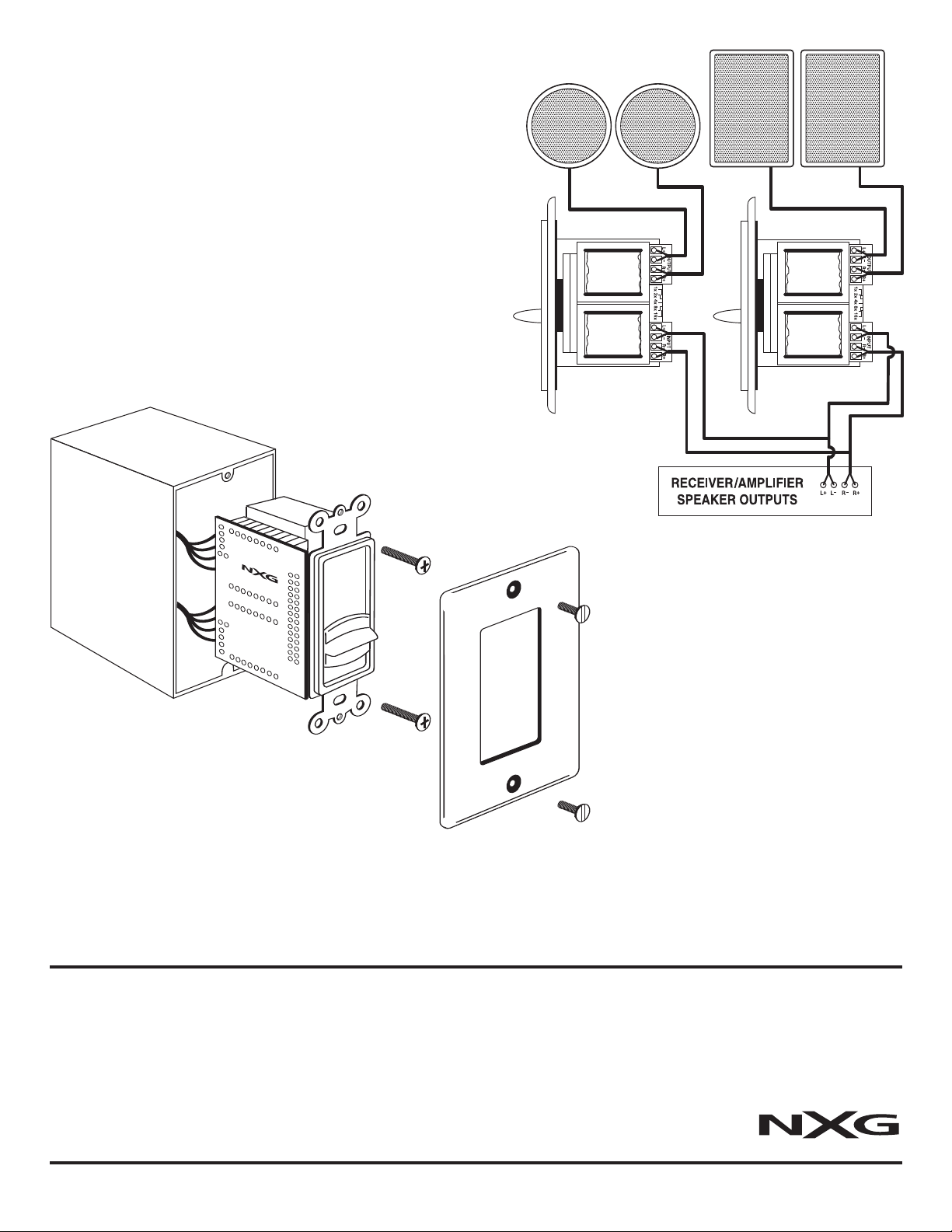
Wiring Instructions (Fig. 2)
The NX-VMS100 has detachable connector blocks to which the amplifier
and speaker wires should be connected. When connecting the speaker
leads from the amplifier outputs to the volume controls blue input con-
ector block, strip about an 1/8 inch of insulation from the wire and twist
n
r solder it so that there are no loose strands. Insert the wires from the
o
mplifiers outputs into the volume control connector block inputs.
a
Note: Wires should stay consistant right + from the amplifier to right + on
the input side of the connecting block. Most speaker wire has some form
of identification such as raised ribs or color coding to help determine positive and negative connections. Connect the speakers to the black output
connector block following the same format as above. When the wires are
connected to blocks, plug them back into the volume control input and
outputs. Do not apply undue pressure while plugging it into the socket.
Make sure the plug is engaged in the socket properly and is not loose.
Caution: Do not reverse the input and output connections or serious
damage may occur to your amplifier.
Fig. 2
Mounting (Fig. 3)
Using the screws provided, install the
completed assembly into a single gang
electrical work box, approximately 18
cubic inches or greater. An open back
electrical box or plaster ring may be
Fig. 3
more convenient to work with.
Note: Avoid mounting the NX-VMS100
next to AC lines or dimmers.
Operational Check
After making all connections, check for proper operation. Switch the system to the ON position. Using either the television or music, slowly
increase the volume on the amplifier/receiver to mid position. Now, slowly raise the volume control slider knob on the NX-VMS100, from its
minimum position up towards its maximum position. You should hear sound emanating from the speakers, increasing in volume as you raise
the volume control slider knob through its twelve steps. Select the level of sound that is most pleasing to you. If no sound is heard from any
or all speakers, switch the system OFF immediately and check for open or loose connections, wrong polarity or shorts in the wires.
One-Y
ear Limited Warranty
If this volume contr
the date of the original customers pur
tive product.
Disclaimer
The warranty stated herein is in lieu of all other war
ing merchantability and fitness for particular purpose and all other liabilities and obligations of
NXG Technology, all of which are expressly disclaimed. NXG Technology has not made and does
not hereby make any other representation, warranty or covenant with respect to the condition,
quality, durability, design, operation, capacity, fitness for use or suitability of this volume control.
Exclusion of Certain Damages
NXG Technology’s liability for any defective product is limited to repair or replacement of the product at our option. NXG Technology shall not be liable for incidental or consequential damages of any
oves to be defective in materials or workmanship within one year from
ol pr
chase, we will, at our option, r
ranties expr
eplace the defec
epair or r
essed or implied includ-
kind or character because of product defects. Some states do not allow limitations on how long an
-
implied warranty lasts and/or do not allow the exclusion or limitation of incidental or consequential
damages, so the above limitations and exclusions may not apply
This Warranty Does Not Cover
Damage caused by abuse, accident, misuse, negligence or improper operation or installation.
oducts that have been altered or modified. Any product whose serial number has been altered,
Pr
defaced or removed. Normal wear and maintenance. Damages caused by shipping (All claims for
shipping damages must be made with the carrier)
arranty Service
W
All warranty repairs must be accompanied by the original
bill of sale. No other document is acceptable or required.
.
NXG
T
echnology •
16648 Nor
th 94th Str
eet
• Scottsdale, AZ
85260 • 1-800-733-0008
 Loading...