

Page 1

NX-PRO6222DVC Dual Voice Coil
Ceiling-Mount Speaker System
OWNER’S MANUAL
Page 2
Congratulations on choosing
NXG Pro Series Architectural
Loudspeakers. Like all NXG prod-
cts, great care has been taken in
u
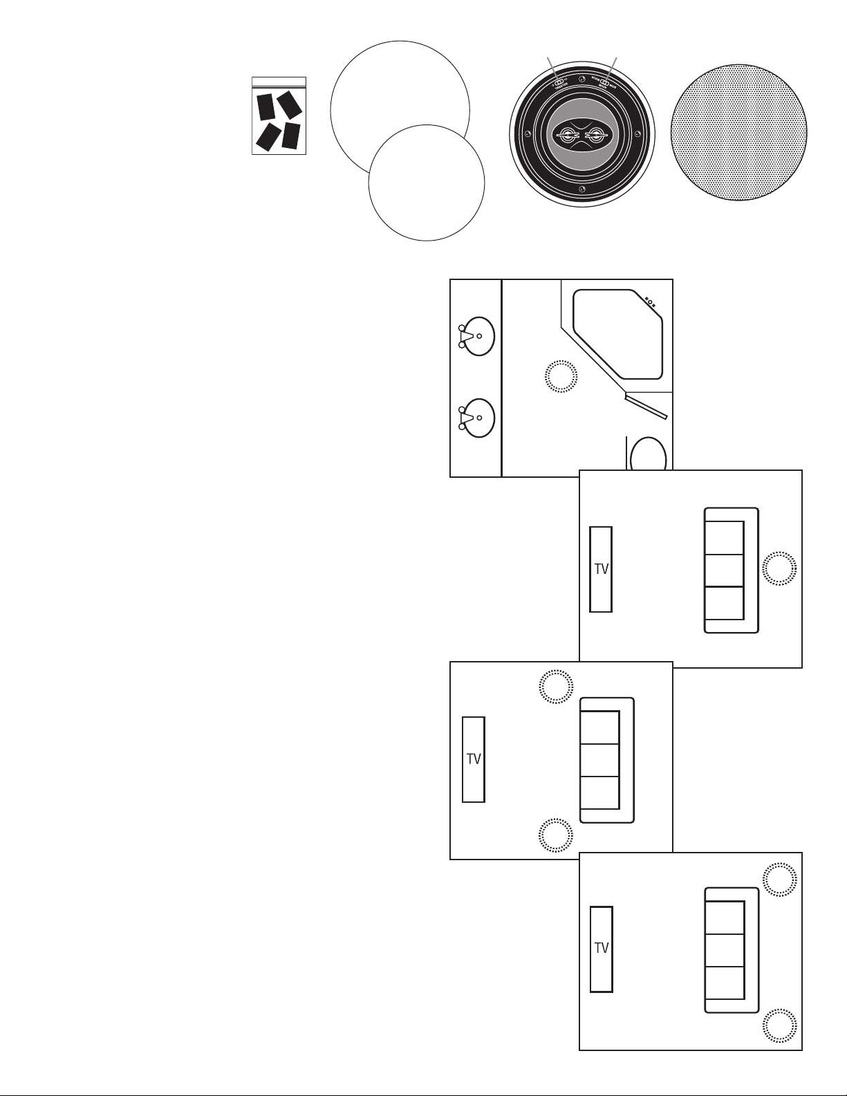
Painting masks
their design. Their combination of
dvanced engineering and state-of-
a
the-art materials will provide you
with years of listening pleasure,
while blending smoothly into your
Black grille
dhesive
a
Cutout templates
home’s decor. Before you get started, it is a good idea to identify all
the parts and hardware (See Fig. 1).
FIG. 1
Placing Your Ceiling Speaker
for Dual Channel Stereo Operation
Placement can make all the difference in how your speaker will
sound, and how easy it will be to install. Carefully consider where
your speaker should be positioned. For optimum dual channel
stereo performance, the speaker should be mounted as close as
possible to the center of the main listening area as shown in Fig. 2
position 1. (Note: Set switch to 8 ohm mode, and connect left and
right channels from your receiver to the two sets of input terminals
on the speaker, as shown in Fig. 5B.)
Tweeter Level
Switch
Speaker with self-contained
mounting clamps
Normal/Wide Operating
Mode Switch
Aluminum grille with
foam inner grille cover
FIG. 2
Position 1 for
two channel
(stereo sound)
For Rear Center Surround
Position 1
or Single Channel Surround Operation
For surround rear center, mount the speaker as shown in Fig. 2
position 2. (Note: Set switch to 8 ohm mode, and connect the two
rear channel outputs from your receiver to the two sets of input
terminals on the speaker, as shown in Fig. 5B.) Avoid mounting the
speaker in stud cavities containing electrical wiring, heating ducts,
water pipes, etc. Make sure the wall or ceiling materials are sturdy
Position 2
for rear center
(two channel)
surround
enough to support the weight of the speaker. Since the NXPRO6222DVC is also designed to be used as a single channel
speaker with wide dispersion, it makes a superb surround sound
rear or side speaker. You can mount the unit in the ceiling slightly
in front of or behind the listening position, left and right, as shown
in Fig. 2 positions 3 and 4. (Note: Set switch to 4 ohm mode, and
one channel from your receiver to only one set of
connect ONL
Y
input terminals on the speaker, as shown in Fig. 5A.)
Tweeter Level Adjustment (Fig. 1)
The tweeter level switch allows you to tailor the speakers’ fr
esponse to better match the room’s acoustics. As an example, if a
r
room has a hardwood floor, which makes it acoustically brighter
sounding, you may want to adjust the tweeter level contr
pensate. The nominal factory setting with the switch in the middle
represents a flat acoustic response. Switching the control to +3 will
increase the high frequency slightly to make up for a dead or dull
sounding (high absorbent) room. Switching the control to –3 will reduce the high frequency
output for bright sounding reflective r
ooms. You can experiment with the level to find the
sound that’s most pleasing to you in your particular listening environment.
equency
ol to com-
Position 3
Position 2
Position 3 or 4
for single channel
surround sound.
Normal/ Wide Operating Mode Control (Fig. 1)
s sound field is directional relative to the
With this switch in the “nor
mal” position the tweeter
angle you set with the swivel positioning in Fig. 3. W
tweeter’s high frequency sound field pattern will become very wide and diffuse. This setting
is especially useful for single channel operation as a sur
ound sound.
r
want a diffuse/ambient r
ear sur
’
ith the switch in the “wide” mode, the
sound speaker where you
ound
r
Position 4
Page 3

Adjustable Tilt-Swivel Tweeter Island (Figs. 3A and 3B)
The tweeter island in the NX-PRO6222DVC can be directed toward the listening area
allowing you to tailor the speaker's dispersion pattern to better fit the desired listening
area. The overall smoothest response is achieved with the tweeter island facing
straight out; however, you may find the sound more pleasing by aiming the tweeters
oward a particular listening position. To adjust the tweeter island direction, you can
t
180°
max.
swivel
rotate the tweeter housing clockwise or counterclockwise (a maximum of 180°) as
shown in Fig. 3A.
Adjust the tweeter island’s angle by holding it on either side of the long axis and tilting
FIG. 3A
the island toward the desired listening position (a maximum of 20° each direction) as
shown in Fig. 3B.
Speaker Installation In Existing Construction (Fig. 4)
Once you have selected the location for your speakers, you are ready to install them.
You will need the following:
• Stud Finder • Drill & Drill Bits • Wire Cutter/ Strippers
• Pencil • Utility Knife or Drywall Saw • Small Level
• Masking Tape • Phillips Screwdriver • Speaker Wire
NXG recommends the use of a minimum of 16-gauge wire. For wire options consult your retailer or custom audio contractor.
1. NXG Architectural Speakers are designed to be installed in the wall or ceiling area between studs. Using a stud finder, make sure you are
between two studs. Using the supplied template, trace around the outside with a pencil.
2. Cut the hole using your drywall saw. You may want to start with a small hole in the center of the outline. This will allow you to check for
any obstructions that may exist behind the desired location. CAUTION: Be certain electrical wiring, water pipes or heating ducts do not
interfere in the planned installation areas prior to drilling or cutting the wall. See Fig. 4.
3. Run speaker wire from your amplifier, volume control or speaker switching device to the speaker location.
4. Carefully remove the grille and inner grille backing. (Note: The open cell foam inner grille backing is designed to hide speaker components
from view and may be removed if desired.) If you like the standard white finish of your NXG speakers, skip to step 5, but if if you want your
speakers to blend in with a colored wall or ceiling, now is the time to paint your speaker’s outer frame and perforated grille. (Remove the
foam inner grille backing and put it aside in a clean and dust free area for later reinstallation if desired.) The speaker’s outer surface will accept
ordinary latex wall paint or aerosol spray paint. Because the speaker baffle surface behind the grille should remain unpainted, you will need to
cover this area with the supplied cardboard paint mask. Cover the speaker’s interior black surface, woofer and tweeter. Paint the outer speaker
frame and grille separately. (Grille painting hint: Use a paint roller that is nearly out of paint to first paint the inside of the grille, then the outside. This will avoid paint filling the grille perforations.)
5. Attach the wire to the input terminals (right and left) on the rear
of the speaker for stereo operation and set the switch in Fig. 5B to
the “8 ohm” mode. For single channel operation you can attach
one set of wires to either set of input connectors and set the
switch in Fig. 5A to the “4 ohm” mode. Remember to maintain
proper polarity with the amplifier by attaching the positive (+) lead
to the red terminal and the negative (-) lead to the black terminal.
6. See Figs. 5A and 5B on r
everse. W
ith the speaker wire(s)
attached to the speaker, slide the speaker up inside the cut-out
hole. Center the speaker in the cut-out hole and turn the four
locking scr
ews clockwise until the speaker is drawn up snugly
to the wall board from behind, clamping the speaker in place.
Try to tighten each screw equally. Replace the speaker grill by
gently pr
essing it into place.
FIG. 4
20° max.
tilt left
FIG. 3B
20° max.
tilt right
New Construction
1. Deter
mine speaker location and mark it on your plans for futur
2. If possible, run speaker wires after HVAC and electrical wiring is in place.
3. Secure speaker wires in place along the run with insulated staples only and be careful not to pierce the wire’s insulation. Allow a bit of
slack for expansion of building materials.
4. Needless to say, the actual speaker should not be installed until the wall board is in place. In the meantime, leave several feet of wire
coiled up and secured at the back side of the mounting hole.
5. To complete the installation follow steps 2 through 6 above.
e reference.
Page 4

FIG. 5A
For single
channel
operation,
set switch to
4 ohm mode
4 ohm /8 ohm
switch
FIG. 5B
NX-PRO6222DVC Specifications
Maximum Power Handling: 5 - 120 watts
Sensitivity: 90dB @ 1 watt/1 meter
Frequency Response: 40 Hz-22,000 Hz
Driver Complement: 61/2˝ (165mm) dual voice coil metallic
nodized injection-molded radiative cone woofer
a
with rubber surround
Dual 3/4˝ (19mm) liquid-cooled metallic anodized dome tweeters
Nominal Impedance: 8 ohms in two channel (stereo) mode,
4 ohms mono mode
Grille: Corrosion-resistant powder coated aluminum
Overall Dimensions: 91/4˝ (diameter) round x 33/4˝D
/
1
Required Ceiling Cut-out: 8
NXG Speakers Three-Year Limited Warranty
If the NXG speaker system proves to be defective in workmanship or
materials within three years from the date of the original customer’s
purchase, we will, at our option, repair or replace the defective product.
Limitation of Implied Warranties
Any implied warranties, including warranties of merchantability and
fitness for a particular purpose, are limited in duration to the length
of this warranty.
Exclusion of Certain Damages
8
˝ (diameter) round
For two
channel
operation,
set switch to
8 ohm mode
4 ohm /8 ohm
switch
Operational Check
After making all connections it’s a good idea to make sure everything
is working properly. Turn on your surround or stereo system making
sure the volume control is turned down and that the balance control
is in the center position. Activate a musical or movie source. Gently
turn up the volume, you should hear sound coming fr
om the speaker
NXG speaker. If no sound is hear
d fr
system immediately and check for open or loose connections, wrong
polarity or shorts, or pr
oper sour
ce selection.
om your new
, switch of
f the
NXG’s liability for any defective product is limited to repair or
replacement of the product at our option. NXG shall not be liable
for incidental or consequential damages of any kind or character
because of product defects. Some states do not allow limitations on
how long an implied warranty lasts and/or do not allow the exclusion
or limitation of incidental or consequential damages, so the above
limitations and exclusions may not apply.
This Warranty Does Not Cover:
Damage caused by abuse, accident, misuse, negligence, or
•
oper operation.
impr
• Any product whose serial number has been altered, defaced,
emoved.
or r
• Products that have been altered or modified.
mal wear and maintenance.
Nor
•
Damages caused by shipping. (All claims for shipping damage
•
must be made with the carrier.)
Warranty Service
Warranty service must be performed by an authorized service center,
usually a NXG speaker systems dealer or its authorized agent. Y
may obtain a list of authorized service centers by contacting NXG. All
epairs must be accompanied by the original bill of sales. No
ranty r
war
other document is acceptable or is required. This warranty gives you
specific legal rights, and you may also have other rights which vary
om state to state.
fr
NXG reserves the right to revise speaker system specifications without notice.
ou
16648 North 94th Street
Scottsdale, AZ 85260
1-800-733-0008
 Loading...