

Page 1
NX-MOUNT-TLT-M / NX-MOUNT-TLT-L
Medium & Large Tilt Mount
INSTRUCTION MANUAL
V1
CAUTION: DO NOT EXCEED MAXIMUM LISTED WEIGHT
CAPACITY. SERIOUS INJURY OR PROPERTY DAMAGE
MAY OCCUR!
Tilt Mount: Medium (M) / Large (L)
Max Screen Size: 55” (M) / 70” (L)
Max weight: 100lbs (M) / 150lbs (L)
P1
Page 2
Congratulations on the purchase of your new TV Mount. At NXG
Technology we design our products to be simple to use, durable, &
furnctional.
Like all NXG products, our mount line has evolved from hours of
rigorous testing by our engineers and customers and were
designed to provide you with years of enjoyment.
Please take a moment to review the installation instructions to
ensure that you get the most from your new mount.
support@nxgtechnology.com
DISCLAIMER – WARNING INFORMATION
Disclaimer – NXG™ has extended every effort to ensure to accuracy and completeness of this manual. However, NXG does not claim that the information
covers all installation and or operational variables. The information contained in this document is subject to change without notice or obligation of any kind.
Regarding the information contained herein, NXG makes no representation of warranty, expressed or implied, and assumes no responsibility for accuracy,
sufficiency, or completeness of the information contained in this document.
WARNING: FAILURE TO READ, THOROUGHLY UNDERSTAND, AND FOLLOW ALL INSTRUCTIONS CAN RESULT IN SERIOUS PERSONAL INJURY,
DAMAGE TO PERSONAL PROPERTY, OR VOIDING OF FACTORY WARRANTY!
It is the responsibility of the installer to ensure all components are properly assembled and installed using the instructions provided. If you do not understand these
instructions or have any questions or concerns, please send questions to support@nxgtechnology.com
Do not attempt to install or assemble this product if the product or hardware is damaged or missing. The included hardware is designed for use on vertical walls
constructed of wood studs or solid concrete. A wood stud wall is defined as consisting of a minimum of 2x4 wooden studs (2” wide by 4” deep) with a maximum of
5/8” drywall. The included hardware is not designed for use with metal studs or cinderblock walls. If you’re uncertain about the construction of your wall, then
please consult a qualified contractor or installer for assistance. For a safe installation, the wall you are mounting to must support 4 times the weight of the total load.
If not, then the surface must be reinforced to meet this standard. The installer is responsible for verifying that the wall structure and hardware used in any
installation method will safely support the total load.
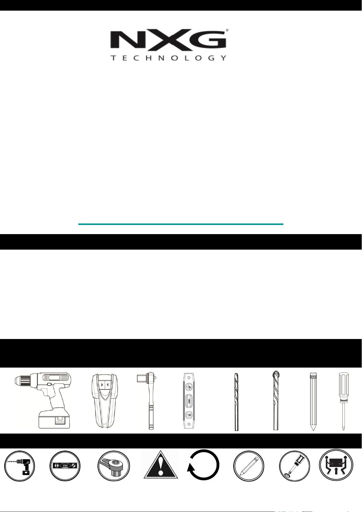
TOOLS NEEDED
SYMBOLS
Drill
Level
Caution
Tighten Socket Wrench
7/32”
5.5 mm
3/8”
10 mm
Pencil Mark
Screwdriver
Heavy!
P2
Page 3
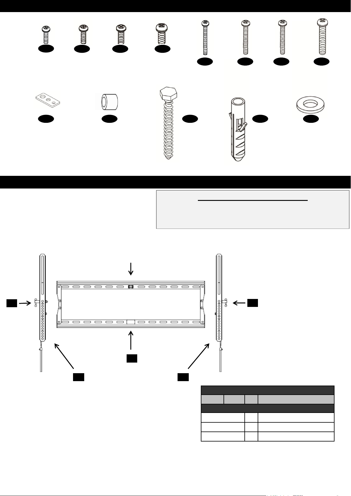
HARDWARE PART NUMBERS
1
M4 x 12
X 4
9
SQUARE
WASHER
X 4
2
M5 x 12
X 4
3
M6 x 15
X 4
10
5mm
SPACER
X 8
PRODUCT COMPONENT PARTS
4
M8 x 15
X 4
M4 x 25
X 4
Lag Bolts
X 4
6 5 7
M5 x 25
X 4
12
CONCRETE
ANCHOR
X 4
M6 x 25
X 4
STEEL
WASHER
X 4
Universal Adapter Range (W x H)
Minimum: 100mm x 100mm (Medium and Large)
Maximum: 430mm x 400mm (Medium)
Maximum: 660mm x 400mm (Large)
8
M8 x 25
X 4
13 11
B
C
Bubble Level
A
C
B
Product Components
Qty
Contents
A 1 Wall Plate
B 2 Vertical Rails
C 1 Locking Mechanism
Description
P3
Page 4
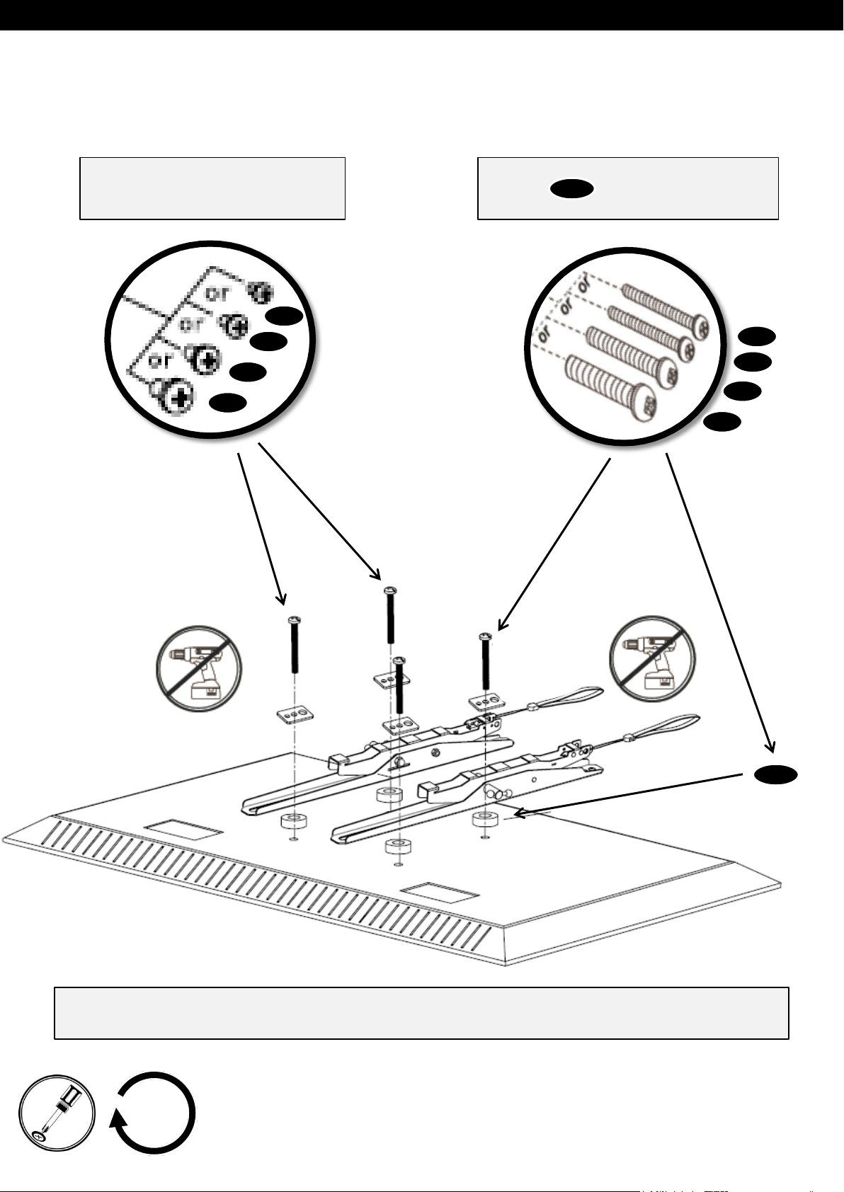
STEP 1- ATTACH VERTICAL RAILS TO BACK OF FLAT PANEL
Hardware 1, 2, 3, & 4 to be used with
panels when back of panel is flat
with no obstructions.
1
2
3
4
Hardware 5, 6, 7, & 8 to be used with
spacers to provide clearance for
cables and connectors when necessary
10
6
7
8
5
Place flat panel face down carefully on flat surface (use blanket or towel to protect front
of flat panel) and attach vertical rails
X4
10
P4
Page 5

STEP 2- EXPAND WALL PLATE TO OPEN POSITION
Hold top and bottom horizontal rails and open wall plate.
Top horizontal rail
Bottom horizontal rail
Due to potential pinching, do not hold
side rails when expanding back-plate
P5
Page 6
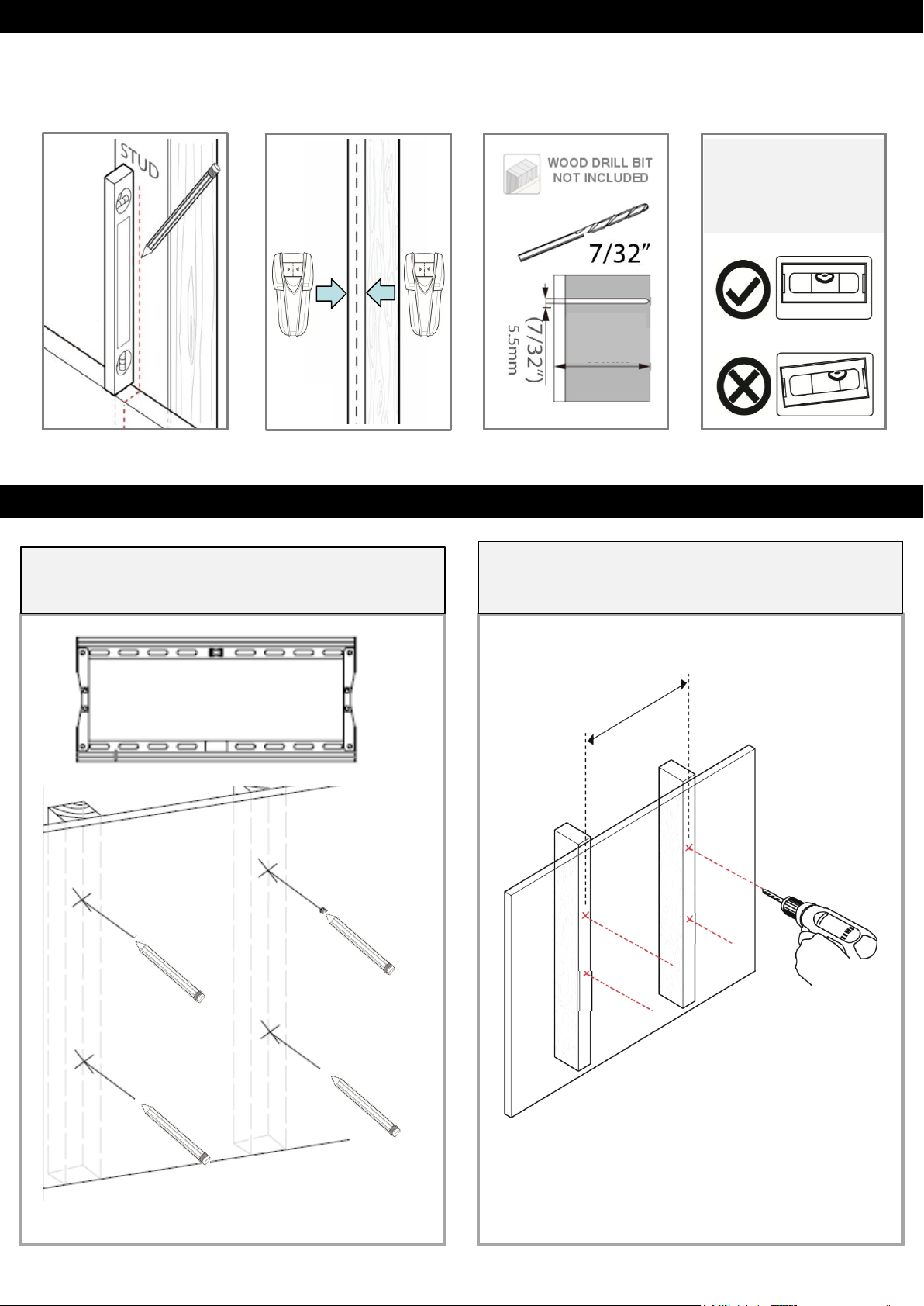
STEP 3- WOOD STUD INSTALLATION (CONCRETE INSTALLATION SKIP TO 4)
Find stud, mark edge and drill pilot holes in center locations
.
LEVEL WALL PLATE
WITH INCLUDED
BUBBLE LEVEL AND
MARK HOLES FOR
DRILL BIT PILOT HOLE
(2 1/3”)
60mm
STEP 3 A & B – LOCATE WOOD STUDS AND DRILL PILOT HOLES
Mark center of wood using stud finder and pencil,
use wall plate to level and mark pilot holes.
Drill 4- pilot holes
P6
Page 7

STEP 4 C – MOUNT WALL PLATE TO WALL
16” STUD (Medium Fixed Mount)
16” or 24” STUD (Large Fixed Mount)
13
11
13
11
X4
P7
Page 8

STEP 4 – SOLID CONCRETE INSTALLATION
Use wall plate to mark mounting locations/ drill pilot holes
Level
Solid Concrete
Drill Bit
DRILL BIT
NOT INCLUDED
Drill Pilot Hole
STEP 4 A & B – POSITION WALL PLATE, MARK, & DRILL PILOT HOLES
Position wall plate to desired location, level, and
mark pilot locations with pencil.
Drill 4- pilot holes
P8
Page 9

STEP 4 C – MOUNT WALL PLATE TO WALL
12
13
11
13
11
X4
P9
Page 10

STEP 5A- ATTACH PANELTO WALL PLATE & ADJUST TILT ANGLE
Hang vertical rails with flat panel attached
Vertical Rails
Flat Panel
Wall Plate
Pull spring lock
cord down and
gently push
Heavy,
Assistance
Required
bottom of panel
to wall and
release spring
lock. Panel is
now locked on
to wall plate.
Rotate lever
clockwise to hold
desired tilt
STEP 5B- ADDITIONAL SECURITY FEAUTURE (OPTIONAL)
Locking
Mechanism
Vertical Rails
Flat Panel
Wall Plate
Vertical Rails have 7mm hole located at the
bottom for placement of pad lock for additional
theft security
P10
Page 11

ADDDENDUM- PRODUCT DIMENSIONS AND SPECIFICATIONS
NX-MOUNT-TLT-M
NX-MOUNT-TLT-L
P11
Page 12

WARRANTY INFORMATION
Manufacturer warrants this product against defects in material or workmanship for the original
purchaser of the product with the following conditions:
WARRANTY PERIOD:
"The three-Year Limited Manufacturer’s Warranty” covers this product against defects in materials or
workmanship from the date of purchase by the original consumer for a period of three (3) years for
parts and labor.
SERVICE:
If the product fails under normal use due to a manufacturing defect within the warranty period, the
consumer will be responsible for the cost of shipping the product to an authorized service center NXG Technology will pay for the return shipment. Manufacturer will repair or replace the defective
item with a new or factory rebuilt replacement at Manufacturer’s discretion. The warranty will be
equal to the remainder of the original limited warranty period on the original product or for 90 days
after the date of repair / replacement, whichever is longer. All services must be performed by an
Authorized Service Center. All replaced parts will be the property of Manufacturer.
To obtain warranty service please send an email to support@nxgtechnology.com.
COVERAGE:
Manufacturer's liability under this limited warranty shall in no event exceed the cost of authorized
repairs, replacement with a similar product, reimbursement for authorized repairs or replacement, or
the original cost of the product at the time of purchase, whichever is less.
• This warranty is valid in the continental United States of America.
• Proof of purchase in the form of a bill of sale, invoice or sales receipt, which is evidence that the
unit is within the warranty period, must be presented to obtain warranty service
LIMITATION OF LIABILITY:
There are no other expressed warranties, whether written or oral, other than this printed limited
warranty. All implied warranties, including without limitation the implied warranties or merchantability
or fitness for a particular purpose, are limited to the durations of this limited warranty.
In no event shall NXG Technology be liable for incidental or consequential damages of any nature
whatsoever, including but not limited to lost profit or commercial loss, to the full extent those
damages can be disclaimed by law.
Some states do not allow the exclusion or limitation of incidental or consequential damage, or
limitation of the duration of implied warranties, so the preceding limitations or exclusions may not
apply to all purchasers. This warranty gives the original purchaser specific legal rights, and you may
also have other rights, which may vary from state to state.
P12
 Loading...