

Page 1
NX-MOUNT-ART-L
Large Full Motion Mount
INSTRUCTION MANUAL
V1
V1
CAUTION: DO NOT EXCEED MAXIMUM LISTED WEIGHT
CAPACITY. SERIOUS INJURY OR PROPERTY DAMAGE
MAY OCCUR!
Small Full Motion Mount
Max Screen Size: 70”
Max weight: 125lbs
P1
Page 2
Congratulations on the purchase of your new TV Mount. At NXG
Technology we design our products to be simple to use, durable, &
furnctional.
Like all NXG products, our mount line has evolved from hours of
rigorous testing by our engineers and customers and were
designed to provide you with years of enjoyment.
Please take a moment to review the installation instructions to
ensure that you get the most from your new mount.
support@nxgtechnology.com
DISCLAIMER – WARNING INFORMATION
Disclaimer – NXG™ has extended every effort to ensure to accuracy and completeness of this manual. However, NXG does not claim that the information
covers all installation and or operational variables. The information contained in this document is subject to change without notice or obligation of any kind.
Regarding the information contained herein, NXG makes no representation of warranty, expressed or implied, and assumes no responsibility for accuracy,
sufficiency, or completeness of the information contained in this document.
WARNING: FAILURE TO READ, THOROUGHLY UNDERSTAND, AND FOLLOW ALL INSTRUCTIONS CAN RESULT IN SERIOUS PERSONAL INJURY,
DAMAGE TO PERSONAL PROPERTY, OR VOIDING OF FACTORY WARRANTY!
It is the responsibility of the installer to ensure all components are properly assembled and installed using the instructions provided. If you do not understand these
instructions or have any questions or concerns, please send questions to support@nxgtechnology.com
Do not attempt to install or assemble this product if the product or hardware is damaged or missing. The included hardware is designed for use on vertical walls
constructed of wood studs or solid concrete. A wood stud wall is defined as consisting of a minimum of 2x4 wooden studs (2” wide by 4” deep) with a maximum of
5/8” drywall. The included hardware is not designed for use with metal studs or cinderblock walls. If you’re uncertain about the construction of your wall, then
please consult a qualified contractor or installer for assistance. For a safe installation, the wall you are mounting to must support 4 times the weight of the total load.
If not, then the surface must be reinforced to meet this standard. The installer is responsible for verifying that the wall structure and hardware used in any
installation method will safely support the total load.
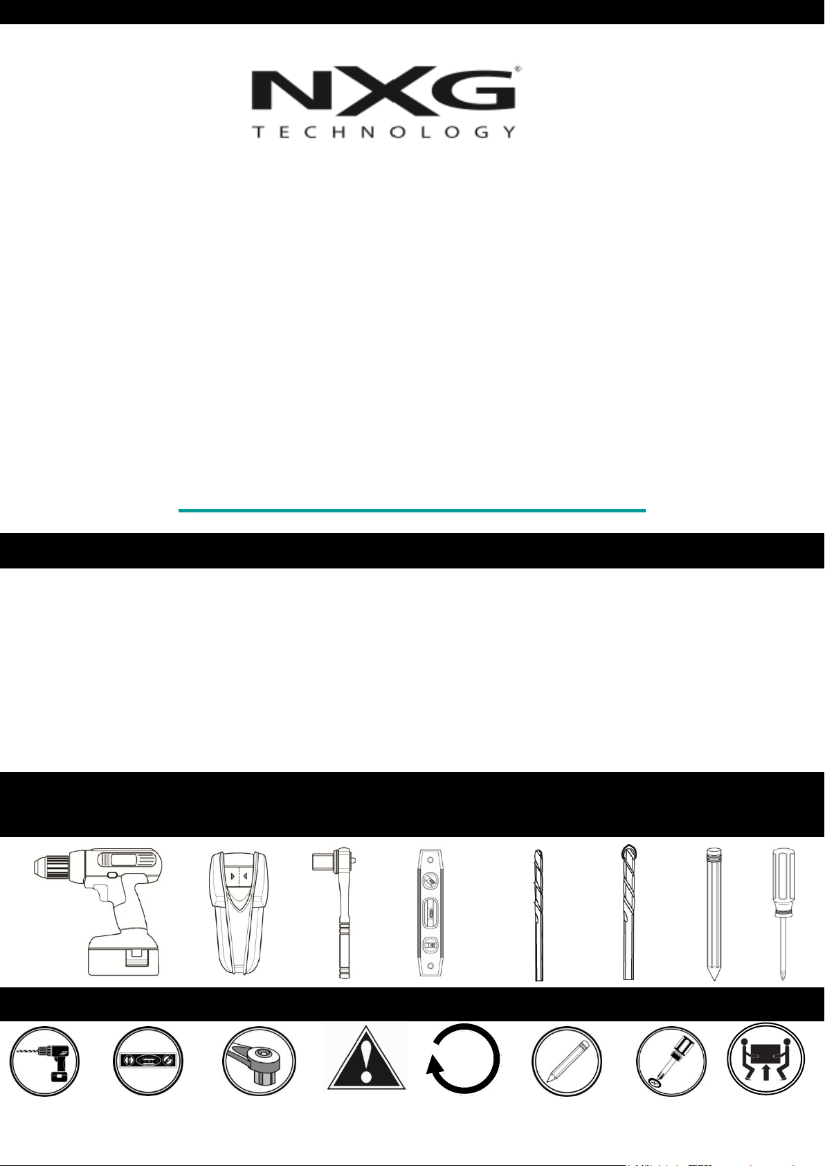
TOOLS NEEDED
SYMBOLS
Drill
Level
Caution
Tighten Socket Wrench
7/32”
5.5 mm
3/8”
10 mm
Pencil Mark
Screwdriver
Heavy!
P2
Page 3
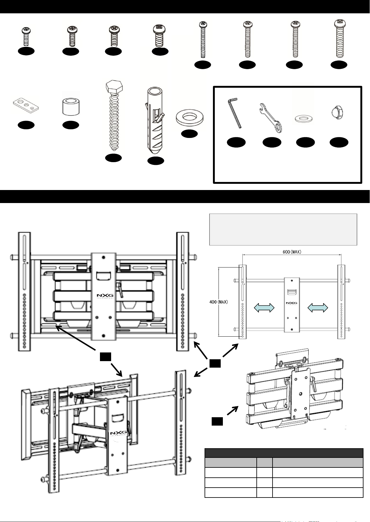
HARDWARE PRODUCT NUMBERS
1
M4 x 12
X 4
9
SQUARE
WASHER
X 4
2
M5 x 12
X 4
10
5mm
SPACER
X 8
3
M6 x 15
X 4
11
8 mm LAG
BOLT
X 4
PRODUCT COMPONENT PARTS
4
M8 x 15
X 4
12
ANCHOR
X 4
M4 x 25
13
STEEL
WASHER
X 4
X 4
6 5 7
M5 x 25
X 4
M6 x 25
X 4
8
M8 x 25
X 4
Adapter Hardware
A1
SECURITY
ALLEN
WRENCH
4 mm
A2
M6 X 5/8”
X 8
WRENCH
A3 A4
M6
WASHER
X 2
M6 ACORN
NUT
X 2
Universal Adapter Range
Minimum: 200mm x 100mm (W X H)
Maximum: 600mm x 400mm (W X H)
A
B
C
Product Components
Contents Qty
A 1 Wall Plate
B 1 Universal Monitor Plate
C 1 Arm Assembly
Description
P3
Page 4
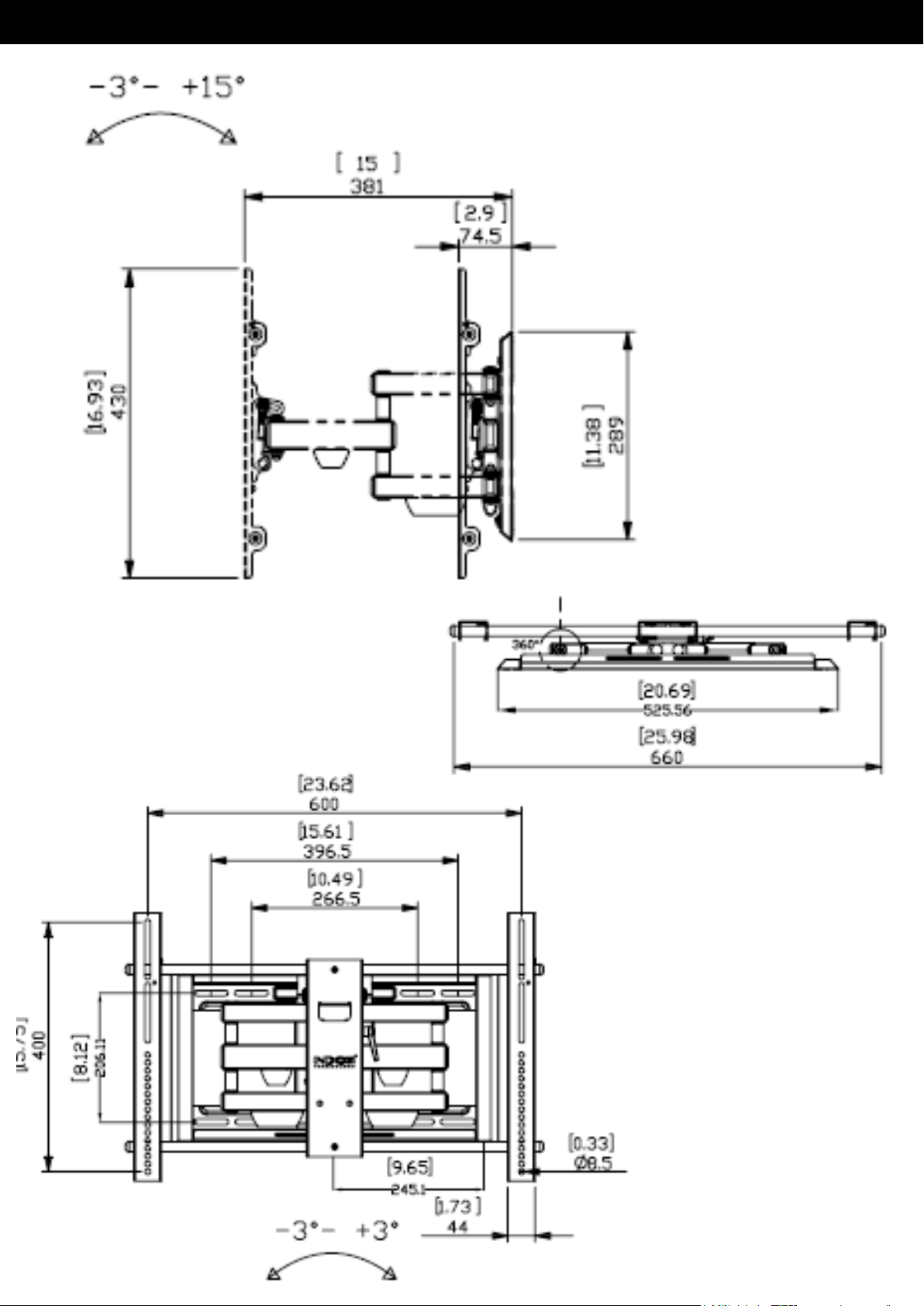
PRODUCT DIMENSIONS AND SPECIFICATIONS
60 lbs
MW60C44
P4
Page 5

CORNER MOUNTING INFORMATION
The Large Full Motion Mount can be
installed in a corner location when
needed. Prior to installing the
Mount it is important to determine
the appropriate corner wall to
install the mount. Please see
diagrams below to assist in
determining the appropriate wall
placement to use.
Drawings below show the Large Full Motion Mount attached to the left
and right of the corner. Depending on the desired angle for viewing,
please review to determine which wall to mount your panel.
Drawing shows panel mounted to left corner
wall
Drawing shows panel mounted to the right
corner wall
Maximum angle for corner placement decreases as panel size increases.
P5
Page 6

STEP 1- FLAT BACK FLAT PANEL (UNIVERSAL MONITOR PLATE)
Connect Universal Monitor Plate to flat panel
SQUARE
WASHER
X 4
1
2
3
4
9
9
B
X4
STEP 1- CURVED BACK FLAT PANEL (UNIVERSAL MONITOR PLATE)
Connect Universal Monitor Plate to flat panel
SQUARE
WASHER
X 4
5
6
7
8
9
10
9
10
Spacers can also be used
to provide clearance for
cables and connectors.
X4
10
B
P6
Page 7

STEP 1- CENTER UNIVERSAL MONITOR PLATE
Monitor Plate must be centered (horizontal plane) on back of flat panel
STEP 1- SECURE UNIVERSAL MONITOR PLATE VERTICAL RAILS
Secure vertical rails to horizontal
chrome rod on Monitor Plate with
pre-installed screws.
X2
P7
Page 8

STEP 2- PRIOR TO EXTENDING ARMS REMOVE ARM ASSEMBLY FROM WALL
PLATE
Prior to extending arms remove 2
security screws with security
Allen wrench to remove Arm
Assembly from Wall Plate. Note- 2
security screws will be used in Step 4 to
reattach arm assembly to wall mount.
Remove Arm Assembly by gently
lifting vertically off Wall Plate. Wall
Plate is now ready to attach to wall
surface (Step 3).
P8
Page 9

STEP 3A- WOOD STUD INSTALLATION (CONCRETE INSTALLATION SKIP TO 3B)
Find stud and mark edge and center locations
Ubique el panel y marque las ubicaciones de los bordes y el centro.
Repérez l'emplacement d'une poutre, puis marquez l'emplacement des bords et du centre de cette poutre.
LEVEL WALL PLATE
WITH INCLUDED
BUBBLE LEVEL AND
MARK HOLES FOR
DRILL BIT PILOT HOLE
STEP 3A – DRILL PILOT HOLE AND MOUNT WALL PLATE
Mount wall plate
Coloque la placa de pared
Montez la plaque murale
13
DRILL BIT
NOT INCLUDED
Secure lag bolts with
steel washer to Wall
Plate
13
11
11
13
X4
P9
Page 10

STEP 3B – SOLID CONCRETE INSTALLATION
Solid Concrete
Concreto sólido
Béton massif
Drill Bit
S. broca
Foret
DRILL BIT
NOT INCLUDED
Level
Nivelado
Level
LEVEL WALL PLATE
WITH INCLUDED
BUBBLE LEVEL AND
MARK HOLES FOR DRILL
BIT PILOT HOLE
STEP 3B – DRILL PILOT HOLES AND MOUNT WALL PLATE
Drill pilot hole
Realice el agujero piloto
Percez le trou de guidage
• Insert Wall Anchors into
Concrete Wall
•Secure Lag Bolts to Wall Plate
13
11
13
Wall Screws
Wall Anchors
1
12
X4
P10
Page 11

STEP 4- ATTACH MOUNT ASSEMBLY TO WALL PLATE
Position Arm Assembly to desired lateral
C
position on wall plate for optimum placement of
Flat Panel. Secure Arm Assembly to Wall plate
using 4mm Security Allen Key.
A
A1
STEP 5- ATTACH UNIVERSAL MOUNT PLATE TO ARM ASSEMBLY & WALL
PLATE
Heavy, Assistance
Required
TRES LOURD ! Cette etape
requiert deux personnes
!PESADO! Necesitara ayuda
para
realizar esta operacion
C
B
A
P11
Page 12

SECURE MONITOR PLATE TO ARM ASSEMBY
A3
Secure Acorn Nut
and Washer on
Monitor Plate to
Arm Assembly
(snug tension only)
B
A4
A3
A4
A2
M6 Washer
M6 Acorn Nut
M6 Wrench
X2
A2
ADJUST TILT TENSION/ POST INSTALLATION LEVEL
Adjust tilt mechanism tension with ratchet
handle
Ratchet handle
for tensioning
tilt mechanism.
Rotate
clockwise to
Tension Tilt
Mechanism. If
more tension is
required pull
lever laterally
and rotate
counter clock
wise and repeat
tension step.
Built-in level feature for post installation
correction
P12
Page 13

WARRANTY INFORMATION
Manufacturer warrants this product against defects in material or workmanship for the original
purchaser of the product with the following conditions:
WARRANTY PERIOD:
"The three-Year Limited Manufacturer’s Warranty” covers this product against defects in materials or
workmanship from the date of purchase by the original consumer for a period of three (3) years for
parts and labor.
SERVICE:
If the product fails under normal use due to a manufacturing defect within the warranty period, the
consumer will be responsible for the cost of shipping the product to an authorized service center NXG Technology will pay for the return shipment. Manufacturer will repair or replace the defective
item with a new or factory rebuilt replacement at Manufacturer’s discretion. The warranty will be
equal to the remainder of the original limited warranty period on the original product or for 90 days
after the date of repair / replacement, whichever is longer. All services must be performed by an
Authorized Service Center. All replaced parts will be the property of Manufacturer.
To obtain warranty service please send an email to support@nxgtechnology.com.
COVERAGE:
Manufacturer's liability under this limited warranty shall in no event exceed the cost of authorized
repairs, replacement with a similar product, reimbursement for authorized repairs or replacement, or
the original cost of the product at the time of purchase, whichever is less.
• This warranty is valid in the continental United States of America.
• Proof of purchase in the form of a bill of sale, invoice or sales receipt, which is evidence that the
unit is within the warranty period, must be presented to obtain warranty service
LIMITATION OF LIABILITY:
There are no other expressed warranties, whether written or oral, other than this printed limited
warranty. All implied warranties, including without limitation the implied warranties or merchantability
or fitness for a particular purpose, are limited to the durations of this limited warranty.
In no event shall NXG Technology be liable for incidental or consequential damages of any nature
whatsoever, including but not limited to lost profit or commercial loss, to the full extent those
damages can be disclaimed by law.
Some states do not allow the exclusion or limitation of incidental or consequential damage, or
limitation of the duration of implied warranties, so the preceding limitations or exclusions may not
apply to all purchasers. This warranty gives the original purchaser specific legal rights, and you may
also have other rights, which may vary from state to state.
P13
 Loading...