

Page 1
OPERATING INSTRUCTIONS OPERATING INSTRUCTIONS
WARRANTY
NXG products are designed to the highest possible value and performance standards. Our
confidence in their quality is such that NXG Technology offers customers this transferable
limited warranty:
NXG Products Two-Year Limited Warranty
If the NXG products prove to be defective in workmanship or materials within two years from
the date of the original customer’s purchase, we will, at our option, repair or replace the defective products.
DISCLAIMER
THE WARRANTY STATED HEREIN IS IN LIEU OF ALL OTHER WARRANTIES, EXPRESS OR IMPLIED,
INCLUDING MERCHANTABILITY AND FITNESS FOR PARTICULAR PURPOSE AND ALL OTHER LIABILITIES AND OBLIGATIONS OF NXG TECHNOLOGY, ALL OF WHICH ARE EXPRESSLY DISCLAIMED.
NXG TECHNOLOGY HAS NOT MADE AND DOES NOT HEREBY MAKE ANY OTHER REPRESENTATION,
WARRANTY OR COVENANT WITH RESPECT TO THE CONDITION, QUALITY, DURABILITY, DESIGN,
OPERATION, CAPACITY, FITNESS FOR USE OR SUITABILITY OF THE NXG PRODUCT.
Exclusion of Certain Damages
NXG Technology’s liability for any defective product is limited to repair or replacement of product at our option. NXG T
of any kind or character because of product defects. Some states do not allow limitations on
how long an implied warranty lasts and/or do not allow the exclusion or limitation of incidental
or consequential damages, so the above limitations and exclusions may not apply.
echnology shall not be liable for incidental or consequential damages
This Warranty Does Not Cover:
• Damage caused by abuse, accident, misuse, negligence, or improper operation.
• Any product whose serial number has been altered, defaced, or removed.
• Products that have been altered or modified.
• Normal wear and maintenance.
• Damages caused by shipping. (All claims for shipping damage must be made with the carrier.)
NX-HDMIX-IR-100-1 HDMI Extender
DEAR CUSTOMER
Thank you for purchasing this NXG Technology product. For optimum performance and safety,
please read these instructions carefully before connecting and operating this product. Please
keep this manual in a safe place for future reference.
FEATURES
• HDCP Compliant
• HD Base-T technology
• HDMI 1.4v
• Supports 10.2 GBPS over a single Cat5e/6 cable
• Supports HD formats: 1080p@60Hz@48 b/pixels, 4Kx2K and support 3D
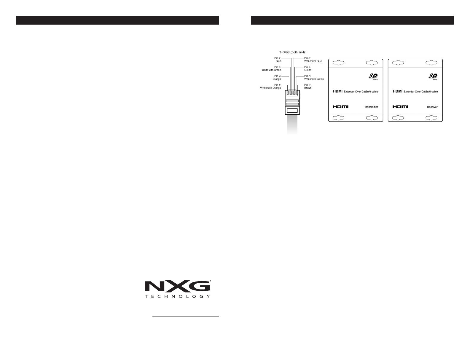
• Extends 1080p Full HD and 3D TV up to 100M (328´) using only one CAT5e /CAT6 cable,
all RJ45connections must follow EIA/TIA T-568B standards
• Offers IR pass through for remote control of source devices
• Supports audio formats (Dolby True-HD/ DTS Master Audio)
• Operates on DC 5V power
• Includes mounting hardware
Warranty Service
Warranty service must be performed by an authorized
service center, usually an NXG dealer or its authorized
agent. All warranty repairs must be accompanied by
the original bill of sales. No other document is acceptable or is required. This warranty gives you specific
legal rights, and you may also have other rights which
vary from state to state.
4 1
Scottsdale,
email: nxgtechnology@gmail.com
web: nxgtechnology.com
AZ
PACKING CONTENTS
1) Main Unit. Transmitter & Receiver HDMI Extender
2) Power adapter DC 5V x2PCS
3) IR-TX cable
4) Operating Instructions
NOTICE
echnology reserves the right to make changes
NXG T
in the hardware, packaging and any accom
documentation without prior written notice.
panying
TABLE OF CONTENTS
Packing Contents
Specifications
Panel Descriptions
Connecting and Operating
Typical Application
Maintenance
Product Service
Warranty
Page 2
OPERATING INSTRUCTIONS OPERATING INSTRUCTIONS
SPECIFICATIONS
Operating Temperature Range -5 to +35° C (-41 to +95° F)
Operating Humidity Range 5 to 90%RH (No Condensation)
Input Video Signal 0.5-1.0 Volts P-P
Input DDC Signal 5 volts p-p (TTL)
Support Video Format DTV/HDTV:480i/576i/480P/576P/720P/1080i/1080P/4Kx2K
3D video
HDMI Output HDMI 1.4+HDCP
Support Audio Format DTS-HD Master Audio Dolby true-HD etc.
Transmission Distance 1080P 328FT/100m(Maximum) over single CAT5E/6 Solid
Power consumption 5 watts (Maximum)
Dimension (L x W x H) 87 x 70 x 24mm
Net Weight 260g (Pair)
Note: Specifications are subject to change without notice. Mass and dimensions are approximate.
PRODUCT SERVICE
1) Damage requiring service: The unit should be serviced by qualified service personnel if:
(a) The DC power supply cord or AC adaptor has been damaged;
(b) Objects or liquids have gotten into the unit;
(c) The unit has been exposed to rain;
(d) The unit does not operate normally or exhibits a marked change in performance;
(e) The unit has been dropped or the cabinet damaged.
2) Servicing Personnel: Do not attempt to service the unit beyond that described in the
operating instructions. Refer all other servicing to authorized servicing personnel.
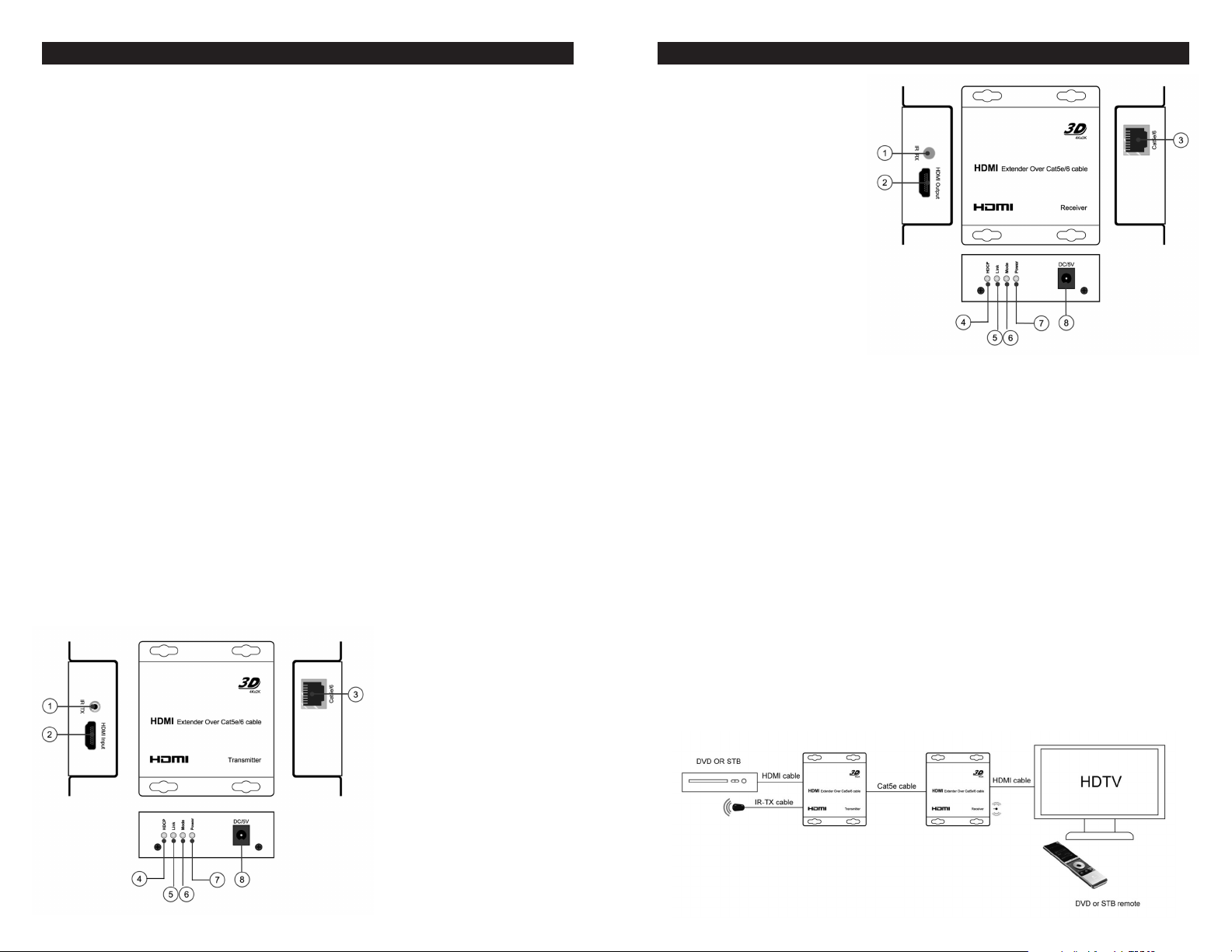
PANEL DESCRIPTIONS
TRANSMITTER (TX)
1. IR-TX port
2. HDMI input
3. Cat5e/6 output port
4. HDCP Status LED
5. Signal Connection Status LED
6. Status mode LED
7. Power LED
8. Power input
RECEIVER (RX)
1. IR-RX
2. HDMI output
3. Cat5e/6 input
4. HDCP Status LED
5. Signal Connection Status LED
6. Status Mode LED
7. Power LED
8. Power input
POWER LED: indicates that power is connected to the unit.
MODE LED: When blinking, the LED indicates the device is active and working.
LINK LED: When the LED is ON, it indicates that an HD Base-T™ connection has been
established between the two units over the CAT5e/CAT6 cable.
HDCP LED: When the LED is ON, it indicates that video content with HDCP protection is
being transferred from unit to unit. When BLINKING, it indicates video content without
HDCP. When the LED is OFF, it indicates that no video signal is present or being transferred.
CONNECTING AND OPERATING
1) Connect the HDMI signal source to HDMI Transmitter.
2) Connect CAT5e /CAT6 cables to both the CAT5e/6 of the transmitter and CAT5e/6 port of
the receiver. The RJ45 connections must follow EIA-TIA 568B standards.
3) Connect the HDMI output from the Receiver (RX) into the display HDMI input.
4) Connect the power supply into Power input jack.
5) Connect IR-TX cable into IR-TX port on the transmitter and affix the emitter onto the
source IR window.
6) Connect the IR-RX cable into the IR-RX port on the Receiver and affix the IR receiver
in direct line of site with the handheld remote control. It is recommended to affix the
receiver on the display frame / bezel or the display stand.
7) Gently Insert/Extract all cables.
TYPICAL APPLICA
TION
2 3
 Loading...