

Page 1

OPERATING INSTRUCTIONS
NX-HDMIM - 4 X4 HDMI Matrix
(Router Type)
FEATURES
• HDCP Compliant
• 4 HDMI inputs and 4 HDMI outputs
• Full HDMI routing functionality
• Supports resolutions up to 1080p
• 4 routing IR RX inputs, 4 common IR TX emitter outputs
• Mounting hardware supplied
• Intelligent EDID functionality
• USB port for upgrading firmware
• Supports 3D video formats
• Compact size
DEAR CUSTOMER:
Thank you for purchasing this NXG Technology product. For optimum performance and safety,
please read these instructions carefully before connecting and operating this product. Please
keep this manual in a safe place for future reference.
NOTE:
NXG Technology reserves the right to make changes in the hardware, packaging and any accompanying documentation without prior written notice.
8 1
Page 2
OPERATING INSTRUCTIONS OPERATING INSTRUCTIONS
TABLE OF CONTENTS
Introduction
Package Contents
Panel Descriptions
Connect and Operation
Specifications
Warranty & Service
PACKAGE CONTENTS
1) Main unit. 4x4 HDMI Matrix
2) 5VDC Power Supply
3) 1x Remote.
4) 4x IR-TX cable
5) 4x IR-RX cable
6) 4x IR-RX cable extender jacks
7) Operating Instructions
PANEL DESCRIPTIONS
Front panel
1 3 4 5 6
2
7 8
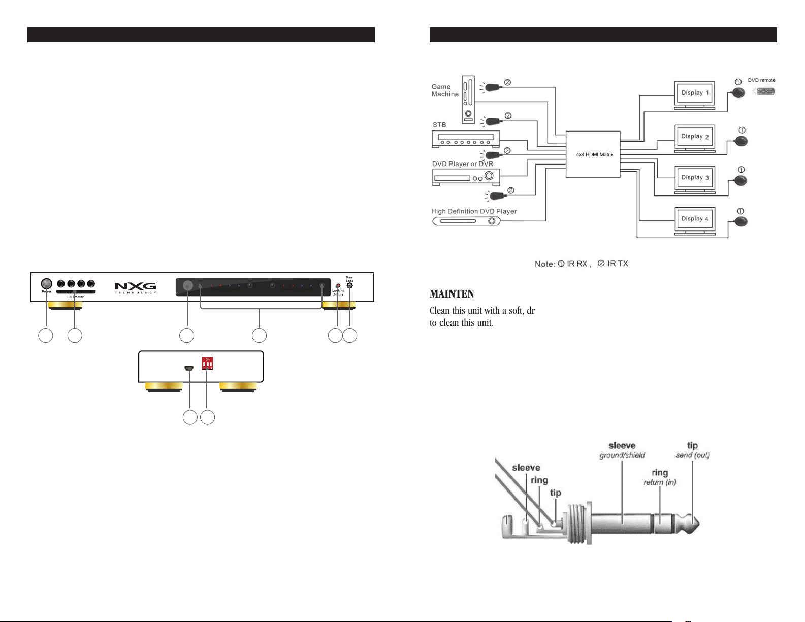
TYPICAL APPLICATION
MAINTENANCE
Clean this unit with a soft, dry cloth. Never use alcohol, paint thinner or other harsh chemicals
to clean this unit.
IR receiver cable extender jacks.
When the display device is not near to the matrix, the IR cable will be too short. There is a pair
of jacks supplied for extending the IR (RX) cable. Please use an appropriate (min. 3 conductor
shielded audio cable) or an additional CAT5e/CAT6 cable to form the IR cable extender.
Additional wires unused should be grounded at the connector on the Matrix end of the line only.
Use the male jack and female jack to extend the IR_RX cable like the
picture below.
1) Power switch
2) IR TX out 1 to 4
3) IR window
4) Output and Input selection /indicator
5) Locking status indicator
6) Key lock selection
7) USB port for ISP only, firmware upgrade port
8) DIP switch
2 3
Tip = IR Signal, Ring = Power, Sleeve = IR Ground
Page 3

OPERATING INSTRUCTIONS OPERATING INSTRUCTIONS
EXAMPLE A:
When the source is a HDMI 1.3 and OUTPUTS 1 through 4 will support HDMI 1.3 displays,
press “OUTPUT 1” and the “lock key” simultaneously, the Matrix will output HDMI 1.3 version
Rear panel
signals. (Deep color mode, 1080P, and Multi-channel audio)
1
1) HDMI Display Outputs 1 and 2
2) HDMI Source Inputs 1 through 4
3) HDMI Display Output 3 and 4
4) Power input jack
5) 4 specifically routed IR emitter outputs 1 through 4
2 3 4 5
CONNECT AND OPERATION
1) Connect the HDMI input sources into 4x4 HDMI Matrix and note the input chosen.
2) Connect the HDMI outputs of the Matrix to the 4 HDMI Display inputs.
3) Connect the IR RX receiving cables into Matrix IR extensions on the back panel. Use the
extension jacks as described and affix the IR RX near or on the Video Display frame or stand
within direct line of sight with the hand held remote. The IR signals are routed to each display,
1 through 4, so as to not interfere with other receivers that may pick up the IR signal.
4) Connect the IR TX emitter cables into Matrix emitter outputs on the front panel. Take note
that the emitter must be affixed over the source IR window. Sometimes finding the IR window
on a source can be a challenge. In order to find the proper placement, move the emitter
carefully over the source
Note: Do not affix the emitter until the placement is tested.
5) Power up all units, the matrix, sources and displays.
6) Use remote or select the button on the front panel to choose the desired input source.
7) Turn on the desired display and note the correct HDMI input must be chosen on the display.
8) The IR TX signals on the front panel are common. Any IR RX signal is will pass through all
4 “IR TX” outputs to the source and the MATRIX controls.
9) Using the SOURCE-SINK Dip Switch. This function applies to a situation when the source HDMI
version exceeds the Matrix HDMI version. This feature can be used to fix most handshake
issues between the source, Matrix and displays. For example: When the TV is HDMI 1.2 version and DVD source is HDMI 1.3 version, it will output HDMI 1.2 version. There are two
modes within the Matrix to update the EDID data according to the DIP setting. When the DIP
is in (0, 0, 0) it is in default MIX mode. Default will automatically output in HDMI 1.2 ver
signals (1080i/1080P and 2CH stereo audio). In most situations, the default mode is ideal
for the application.
until the IR signal makes the source function as required.
sion
4 5
EXAMPLE B:
When the source is a HDMI 1.3 version and OUTPUTS 1 through 4 are connected to displays that
can only support HDMI 1.2 versions, simultaneously press “OUTPUT 1” and the “lock key”.
Regardless of whether the HDMI OUTPUT port is connected to a display that supports HDMI 1.3
or not, it will automatically output HDMI 1.2 signals based on the displays max capabilities.
RESETTING THE MATRIX TO FACTORY DEFAULT
The method to reset the Matrix to all default settings is easy. Make sure the dip switches are set
to (0, 0, 0). Disconnect all HDMI the inputs and outputs. Press “OUTPUT 1” and the “lock key”
simultaneously for at least 3 seconds. All EDID settings of all the four input sources will be reset
to the default setting. The default EDID is 1080P and stereo 2 CH audio.
10) DIP switch settings
Position ID
1 2 3
0 0 0 Default MIX Mode
0 0 1 Reserved for future use
0 1 0 Reserved for future use
0 1 1
1 0 0
1 0 1 Reserved for future use
1 1 0 Reserved for future use
1 1 1 Reserved for future use
Note 1: The matrix will mix the EDID data of the sink devices. The mixed EDID data will use the
lowest resolution of the video and the least number of channels for audio. For example, some
devices support 1080P, some devices only support 1080i, some support 5.1 audio, but some
only support stereo. Then the mixed mode EDID will be 1080i and stereo.
Note 2: If user wants to just use one sink device’s EDID data, this DIP setting can be used (0, 1, 1).
Sink Mode, USE the EDID of the OUTPUT 1 see Note 2 below
Reserved for future use
Page 4

OPERATING INSTRUCTIONS OPERATING INSTRUCTIONS
SPECIFICATIONS
Operating Temperature Range -5 to +35° C (+23 to +95° F)
Operating Humidity Range 5 to 90%RH (No Condensation)
Input Video Signal 0.5-1.0 Volts P-P
Input DDC Signal 5 volts p-p (TTL)
Signaling Rate 2.25Gbit/s
Video Format Supported DTV/HDTV:1080P/1080i/720P/576P/480P/576i/480i
3D video
Audio Format Supported DTS-HD Dolby true-HD
Maximum Transmission Distance <15m (If needed, HDMI extender is optional)
Power consumption 12 watts (Maximum)
Dimension (L x W x H) 290 x 100 x 26mm (17.3˝ x 7.9˝ x 1.7˝)
Mass (Main Unit) 0.7kg /4.4lb
Note: Specifications are subject to change without notice. Mass and dimensions are approximate.
WARRANTY
NXG products are designed to the highest possible value and performance standards. Our
confidence in their quality is such that NXG Technology offers customers this transferable
limited warranty:
NXG Products Two-Year Limited Warranty
If the NXG products prove to be defective in workmanship or materials within two years from
the date of the original customer’s purchase, we will, at our option, repair or replace the defective products.
DISCLAIMER
THE WARRANTY STATED HEREIN IS IN LIEU OF ALL OTHER WARRANTIES, EXPRESS OR IMPLIED,
INCLUDING MERCHANTABILITY AND FITNESS FOR PARTICULAR PURPOSE AND ALL OTHER LIABILITIES AND OBLIGATIONS OF NXG TECHNOLOGY, ALL OF WHICH ARE EXPRESSLY DISCLAIMED.
NXG TECHNOLOGY HAS NOT MADE AND DOES NOT HEREBY MAKE ANY OTHER REPRESENTATION,
WARRANTY OR COVENANT WITH RESPECT TO THE CONDITION, QUALITY, DURABILITY, DESIGN,
OPERATION, CAPACITY, FITNESS FOR USE
OR SUITABILITY OF THE NXG PRODUCT.
Exclusion of Certain Damages
NXG Technology’s liability for any defective product is limited to repair or replacement of product at our option. NXG Technology shall not be liable for incidental or consequential damages
of any kind or character because of product defects. Some states do not allow limitations on
how long an implied warranty lasts and/or do not allow the exclusion or limitation of incidental
or consequential damages, so the above limitations and exclusions may not apply.
This Warranty Does Not Cover:
• Damage caused by abuse, accident, misuse, negligence, or improper operation.
• Any product whose serial number has been altered, defaced, or removed.
• Products that have been altered or modified.
• Normal wear and maintenance.
• Damages caused by shipping. (All claims for shipping damage must be made with the carrier.)
Warranty Service
Warranty service must be performed by an authorized
service center, usually an NXG dealer or its authorized
agent. All warranty repairs must be accompanied by
the original bill of sales. No other document is acceptable or is
legal rights, and you may also have other rights which
vary from state to state.
6 7
required. This warranty gives you specific
Scottsdale, AZ
email: nxgtechnology@gmail.com
web: nxgtechnology.com
 Loading...