

Page 1
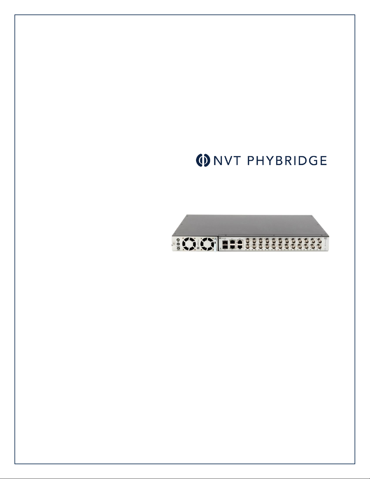
CLEER®24 Switch User Guide
Version 5.3.0
Page 2

Proprietary Notice
Copyright © 2018 NVT Phybridge Inc. All rights reserved.
All information contained in this document is confidential and proprietary to NVT Phybridge Inc.
Any disclosure, duplication, reproduction or transmission of this document or the information it
contains is prohibited without the prior written authorization of NVT Phybridge Inc. NVT Phybridge
believes that at the time of publication, this document accurately reflects CLEER switch features,
requirements and specifications. However, this document may contain errors or omissions, and
NVT Phybridge makes no warranties regarding the content of this document. NVT Phybridge is not
responsible for any loss or damages arising from the use or misuse of this document. The
information contained in this document as well as all product specifications are subject to change
without notice.
Trademarks
NVT Phybridge is a trademark of NVT Phybridge Inc.
All other trademarks, registered trademarks and service marks are the property of their
respective owners.
NVT Phybridge Inc. Corporate Headquarters
3457 Superior Court
Unit 3
Oakville, ON
L6L 0C4, Canada
www.nvtphybridge.com
NVT Phybridge CLEER Switch Hardware Installation Guide
Release 5.3.0 – 2018
®,™ Trademark of NVT Phybridge Inc.
© Copyright 2018, NVT Phybridge Inc.
All rights reserved
Page 3
Warranty Information
All statements in this document concerning the NVT Phybridge CLEER switch are for
informational purposes only. No part of this document constitutes a warranty, either express
or implied, regarding the CLEER switch. Our standard limited warranty is provided with the
sales contract and/or product package.
Service and Support
NVT Phybridge is dedicated to customer satisfaction and the high quality of its products.
Our technical support team is prepared to assist you in maximizing the efficiency and
dependability of your CLEER switch environment and will provide you with an immediate
solution should a problem with your product arise. Contact us to discuss a plan of action.
Returning a CLEER Switch
If you must return a CLEER switch, adapter, or accessory component to NVT Phybridge Inc.,
ensure that all items are adequately protected with insulating material and packaged in the
original carton before shipping. Failure to do so may void the equipment warranty. Consult
the warranty statements included with the sales contract and/or product package. Contact
us for specific RMA requirements before you ship.
Audience
This document is intended for the use of service technicians, system administrators,
information technology experts and other personnel who are qualified to install, configure
and maintain the CLEER switch in the IP network environment. The tasks and procedures
described in this guide require a basic understanding of IP communications, Ethernet LAN
networks and the strategies and solutions currently practiced in your network environment.
This document assumes that you are familiar with the architecture, specifications and
functionality of your network. NVT Phybridge Communications Director (MCD) certification
training is required.
Document Conventions
In this document, some instructions are given particular emphasis to denote cautions,
warnings and notes.
Cautions
A caution contains an instruction that the reader must follow in order to prevent damage to
equipment, network failure or loss of data.
Example:
CAUTION: Do not expose the CLEER switch or any of its components to a magnetic field
or electrostatic charge. Damage to system components could result.
Warnings
A warning contains an instruction that the reader must follow in order to prevent electrical
shock, death or serious injury to personnel.
Example:
WARNING: Ensure that the CLEER switch is independently grounded with a wire
securely attached to the ground lug at the rear of the switch.
Page 4

Notes or Tips
A note or tip provides helpful information related to the topic of discussion.
Examples:
Note: The power supply unit is a field-replaceable part.
Tip: Use the handle on the right side to pull the power supply unit out.
Page 5

C O N T E NT S
i
P h y b r id g e NV T C LE E R Sw i t ch U s er G u i de
Contents
1. Overview ...................................................................................................... 1
About this Guide .......................................................................................................... 1
About the Simple Network Manager .................................................................................... 1
Browser Requirements ................................................................................................... 2
Software Version .......................................................................................................... 2
Logging into the Switch .................................................................................................. 2
Managing Multiple Switches ............................................................................................. 2
2. System Page .................................................................................................. 3
About the System Page .................................................................................................. 3
System > Overview ....................................................................................................... 3
System Overview ...................................................................................................... 4
Ethernet Port Status .................................................................................................. 5
Viewing port status ................................................................................................ 6
Controlling power to downlink ports ............................................................................ 6
System > Performance ................................................................................................... 7
CPU Load ................................................................................................................ 8
Memory (Megabytes) .................................................................................................. 8
Power (Watts) .......................................................................................................... 9
Temperature (Celsius) ................................................................................................ 9
System> Log ............................................................................................................. 10
Selecting the number of events to display ....................................................................... 10
Searching Log entries ............................................................................................... 10
Adding markers to the log .......................................................................................... 11
Downloading the log file ............................................................................................ 11
3. Ethernet Page .............................................................................................. 12
About the Ethernet Page .............................................................................................. 12
Ethernet > Uplink Ports ................................................................................................ 12
Configure GbE Interface ............................................................................................ 13
Configure Management Port ....................................................................................... 13
Configure IP Route .................................................................................................. 14
Viewing Uplink Statistics ........................................................................................... 14
Ethernet > Downlink Ports ............................................................................................. 15
Ports 1-24 ............................................................................................................. 15
Viewing adapter information ................................................................................... 15
Viewing port information ........................................................................................ 16
Downloading the MAC address table ........................................................................... 17
4. VLAN Page .................................................................................................. 18
About the VLAN Page ................................................................................................... 18
VLAN > VLAN Table ..................................................................................................... 18
Adding a VLAN ....................................................................................................... 19
Editing a VLAN ....................................................................................................... 19
Setting the default VLAN ........................................................................................... 19
Deleting VLANs ....................................................................................................... 19
VLAN > VLAN To Port ................................................................................................... 20
Viewing VLAN port details .......................................................................................... 20
Assigning ports to a VLAN........................................................................................... 20
Removing ports from a VLAN ....................................................................................... 21
Refreshing VLAN information ...................................................................................... 21
Page 6

ii
C O N T E NT S
P h y b r id g e NV T C LE E R Sw i t ch U s er G u i de
VLAN > Assign PVID ..................................................................................................... 21
PVID Table ............................................................................................................ 22
Viewing port PVID details for a VLAN ............................................................................. 22
Adding or modifying a port PVID................................................................................... 22
Refreshing VLAN information ...................................................................................... 22
5. Admin Page ................................................................................................. 23
About the Admin Page ................................................................................................. 23
Admin > Setup ........................................................................................................... 23
System Settings ...................................................................................................... 24
Import/Export Configuration ....................................................................................... 25
View the switch configuration .................................................................................. 25
Export configuration from the switch ......................................................................... 25
Import configuration to the switch ............................................................................ 25
Admin > Services ........................................................................................................ 26
Services ............................................................................................................... 26
Remote Log Server .................................................................................................. 27
Network Time Protocol ............................................................................................. 27
Spanning Tree Protocol ............................................................................................. 28
Simple Network Management Protocol ........................................................................... 28
Admin > Terminal ....................................................................................................... 29
Using the Command Line Interface ............................................................................... 29
Adding notes to the switch ......................................................................................... 30
6. Command Line Interface ................................................................................ 31
Command Reference ................................................................................................... 31
Upgrade Procedure ..................................................................................................... 41
Displaying the current installed version .......................................................................... 42
7. Troubleshooting ........................................................................................... 43
Page 7
1 . O V ER V I E W
A b o u t t h i s G ui d e
1
N V T P hy b r id g e C LE E R Sw i t ch U s er G u i de
1. O ve rv ie w
About this Guide
This user guide provides instructions to manage, control and monitor the switch using
the Simple Network Manager.
This guide is intended for operating personnel (sometimes called craft persons). Users
must be familiar with the basic operations of a Layer 2 switch. Access to the hardware
interface is by a computer with a telnet terminal.
About the Simple Network Manager
The Simple Network Manager provides you with a simple and intuitive tool to manage,
control and monitor the switch. Most operations can be performed with a click of the
mouse. The Simple Network Manager also includes a command line interface for
managing the switch.
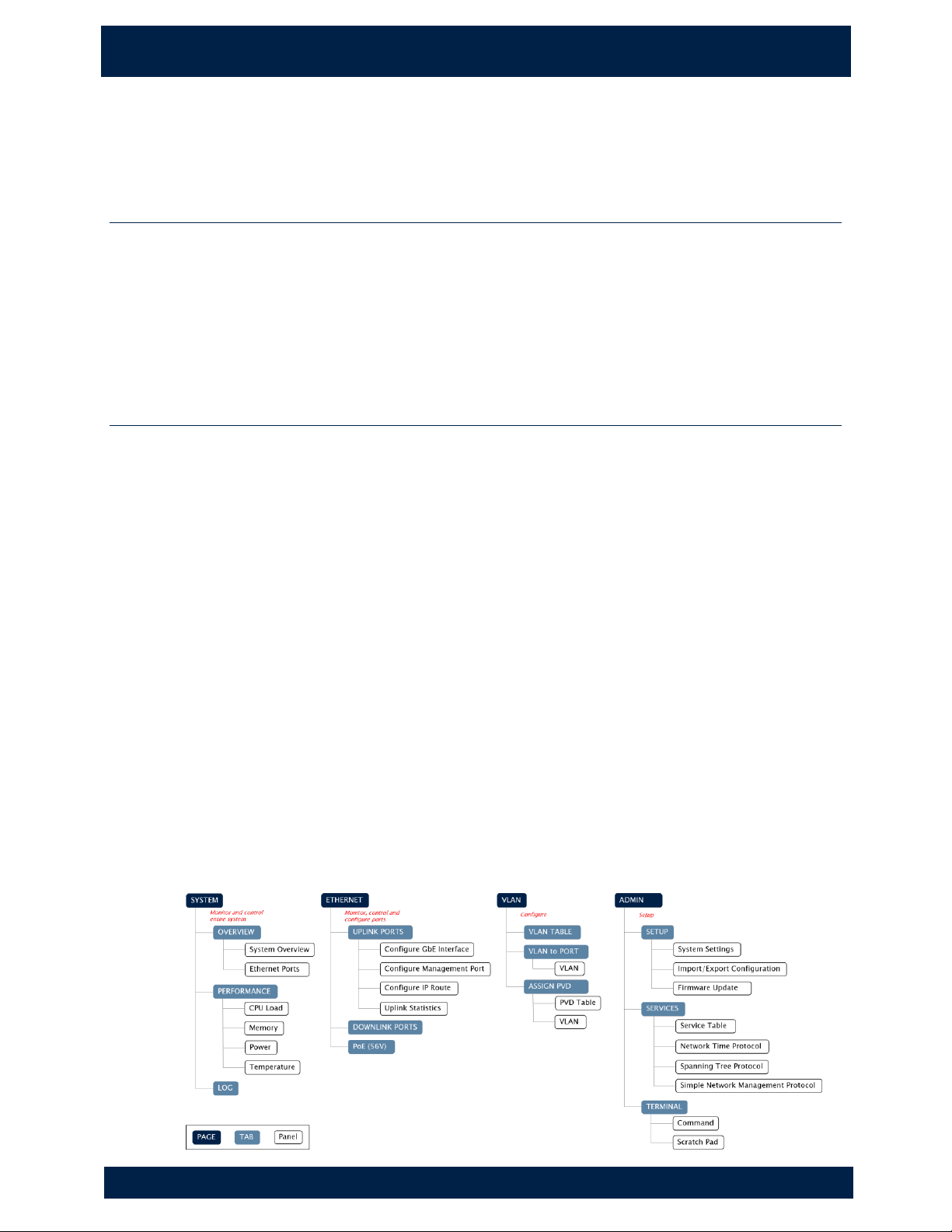
The Simple Network Manager is divided into four main pages, arranged in order of the
frequency that you will typically access them:
System
Provides a real-time overview of the system, and allows you to control downlink
ports and view detailed log activities. See "About the System Page" on page 3.
Ethernet
Provides switch configuration and management as well as uplink and downlink port
management. See "About the Ethernet Page" on page 4.
VLAN
Allows users to view, establish and assign VLANs. See "About the VLAN Page" on
page 20.
Admin
Allows users to setup, configure and manage the switch, enable services and
configure the switch using a command line interface. See "About the Admin Page"
on page 25.
Page 8
2
1 . O V ER V I E W
B r o w s er R eq u i re m en t s
NVT P h y b r id g e CL E E R S w i t ch U se r G u id e
Browser Requirements
The Simple Network Manager supports the following web browsers:
• Google Chrome™ version 21 and higher
• Mozilla Firefox® version 16 and higher
Software Version
The current version of the switch software is 5.3.0.
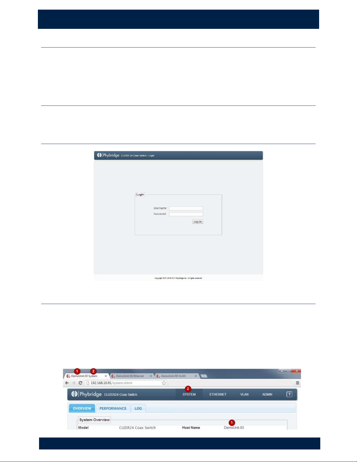
Logging into the Switch
Managing Multiple Switches
When managing multiple switches through the Simple Network Manager, each switch is
shown as a separate browser window or tab. The window/tab title contains the switch
hostname, allowing you to easily identify each switch.
Each tab title is composed of:
1. Hostname of the switch
2. Currently active page on the switch.
Page 9
2 . S Y S TE M P AG E
A b o u t t h e S y s te m P a g e
3
N V T P hy b r id g e C LE E R Sw i t ch U s er G u i de
2. S ys te m Page
About the System Page
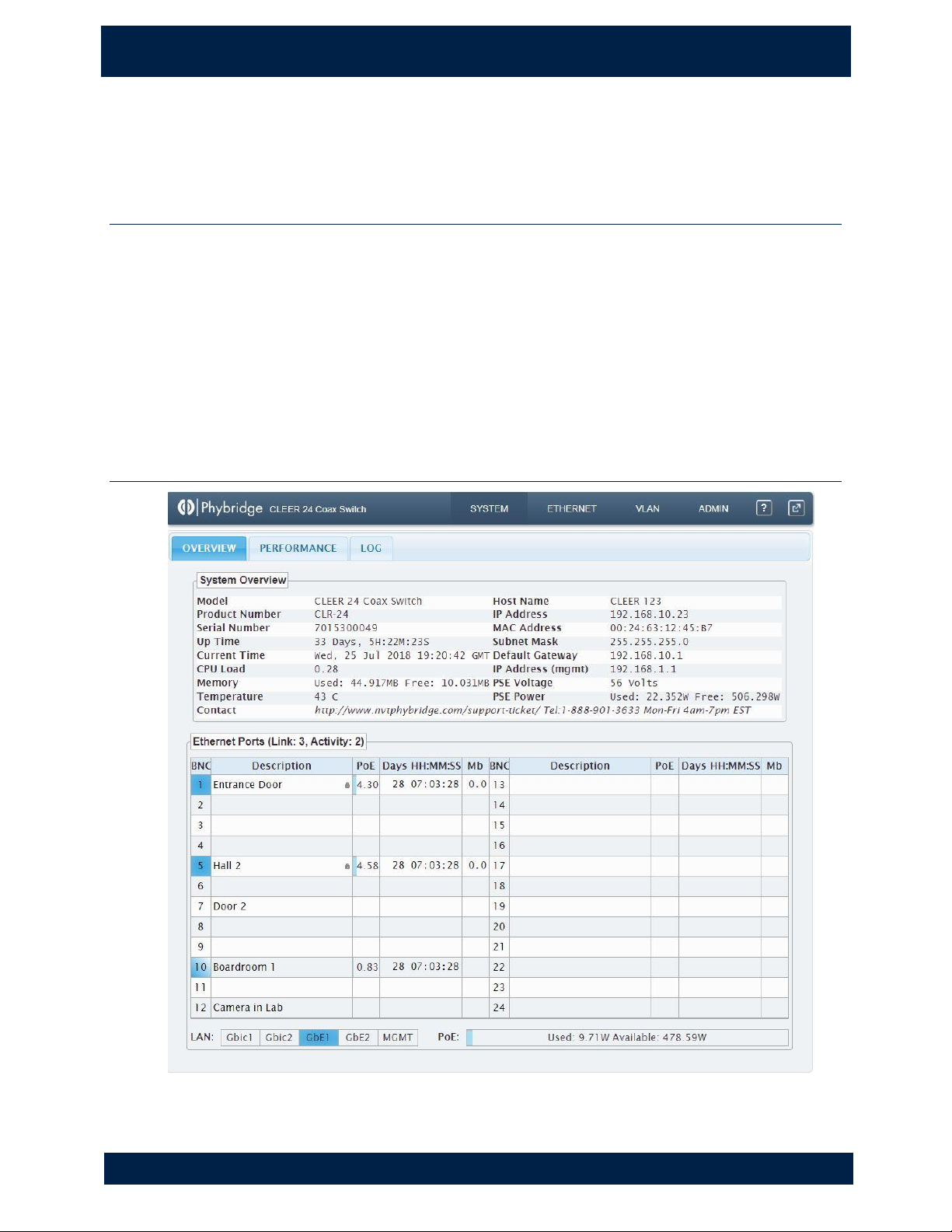
The System page provides high-level switch details, allowing you to monitor the system
in real-time. The data provided on the System page is helpful to troubleshoot most
issues you may encounter.
The System page contains three tabs:
• Overview
• Performance
• Log
System > Overview
Page 10
4
2 . S Y S TE M P AG E
S y s t e m O ve r v i ew
NVT P h y b r id g e CL E E R S w i t ch U se r G u id e
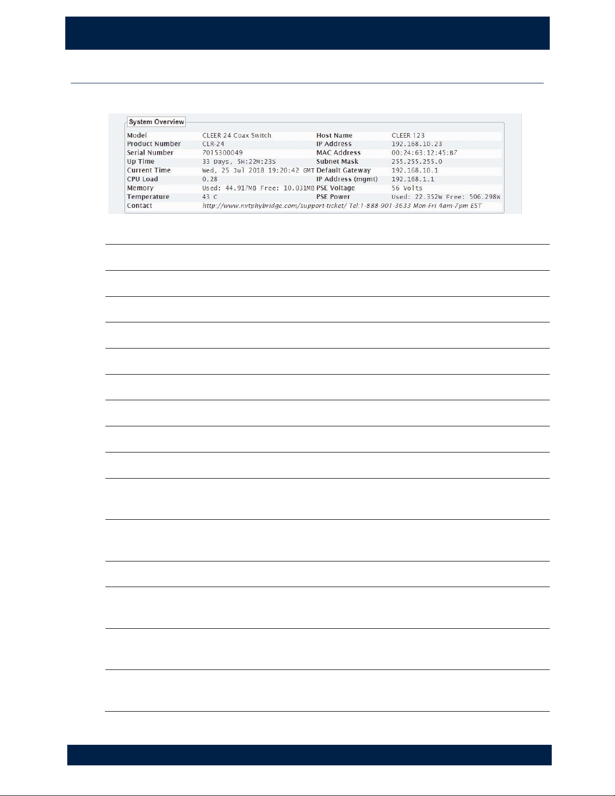
System Overview
Provides an overview of the switch statistics.
Model
Model.
Product Number
Product number.
Software Version
Software version.
Serial Number
Serial number.
Uptime
System uptime. Updated in real-time.
Current Time
Current date and time according to the switch. Updated in real-time.
CPU Load
Current load on the CPU. Updated in real-time.
Memory
Current used and free memory. Updated in real-time.
Temperature
Current temperature. Updated in real-time.
Host Name
Current host name. This field can be configured in Admin > Setup
(see page 25).
IP Address
Current IP address. This field can be configured in Ethernet > Uplink
Ports (see page 14).
MAC Address
Current MAC address.
Subnet Mask
Current subnet mask. This field can be configured in Ethernet >
Uplink Ports (see page 14).
Default Gateway
Current default gateway. This field can be configured in Ethernet >
Uplink Ports (see page 14).
IP Address
(mgmt)
Current management port IP address. This field can be configured in
Ethernet > Uplink Ports (see page 14).
Page 11
2 . S Y S TE M P AG E
S y s t e m O ve r v i ew
5
NVT P h y b r id g e CL E E R S w i t ch U se r G u id e
PSE Voltage
Current output voltage.
PSE Power
Current power usage. Updated in real-time.
Contact
Contact information. This field can be configured in Admin > Setup
(see page 25).
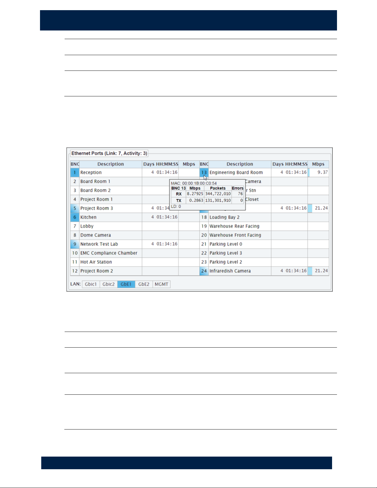
Ethernet Port Status
Provides the uplink and downlink port status; allows you to control power to the
downlink ports.
A downlink port summary above the port boxes indicates how many adapters are
available and how many are connected to endpoints.
BNC
Port number.
Description
Description of the port for easy identification; this is configured in Ethernet
> Downlink Ports (see page 15).
Days
HH:MM:SS
Length of uptime or downtime; see "Viewing port status" below.
Mbps
Megabits per second bandwidth received from the endpoint, displayed as a
real-time moving bar graph. The whole width of the field is 100%: the
number shown is the percentage and the bar is a visual representation
Page 12
6
2 . S Y S TE M P AG E
S y s t e m O ve r v i ew
NVT P h y b r id g e CL E E R S w i t ch U se r G u id e
LAN
Uplink ports. For a breakdown of the packets received to and sent from
these ports, see Ethernet > Uplink Ports (on page 14).
Viewing port status
• Hover over a port number to view port information (link details, MAC address of
the main device and a historical link down count for the port). For a breakdown of
the packet information, see Ethernet > Downlink Ports (see page 15).
• The Days field shows uptime or downtime of adapter connections: black text =
uptime, gold text = downtime. This counter is reset when the port is reset.
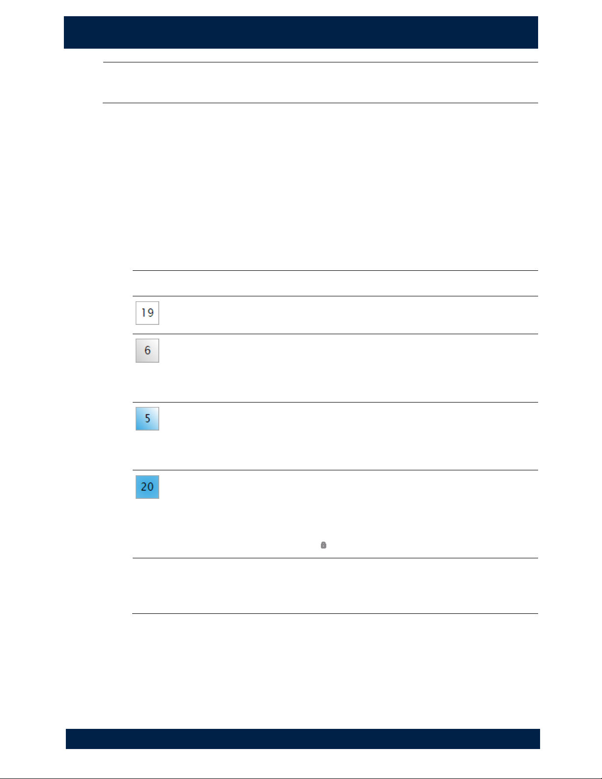
• Port status can be easily identified by the colour and shading of the port box and
number.
Colour
Port Status
White box
Port is available with power; nothing is attached to the port.
Grey
shaded
box
Port power has been manually disabled.
Blue
shaded
box
Adapter is attached to the port; nothing is attached to the
adapter.
Solid blue
box
Adapter is attached to the port; an IP device is connected to the
adapter.
You can lock the port to the currently connected IP device, on
the Ethernet > Downlink Ports page (see page 15). When
locked, a lock icon ( ) appears beside the Description.
Number
changes from
black to red
The port number gradually changes from black to red if there
is a cable fault.
Controlling power to downlink ports
You can turn the power on or off for a port.
1. Double-click a port.
2. Click OK to confirm that you want to turn the port power on or off.
Page 13
2 . S Y S TE M P AG E
S y s t e m > Pe r fo r m an c e
7
NVT P h y b r id g e CL E E R S w i t ch U se r G u id e
System > Performance
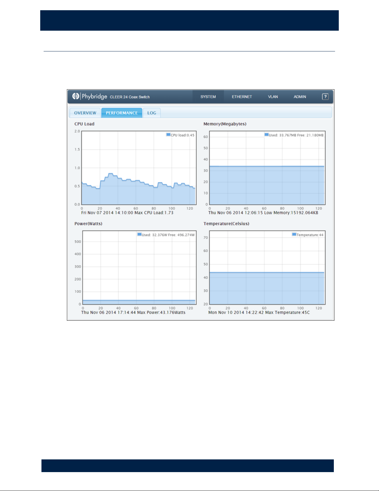
All panels provide current values and the last two minutes of historical data; values are
updated in real-time. Below each panel is the defined threshold (minimum or maximum)
and date of the last indicator reading.
Page 14
8
2 . S Y S TE M P AG E
S y s t e m > Pe r f or m a nc e
NVT P h y b r id g e CL E E R S w i t ch U se r G u id e
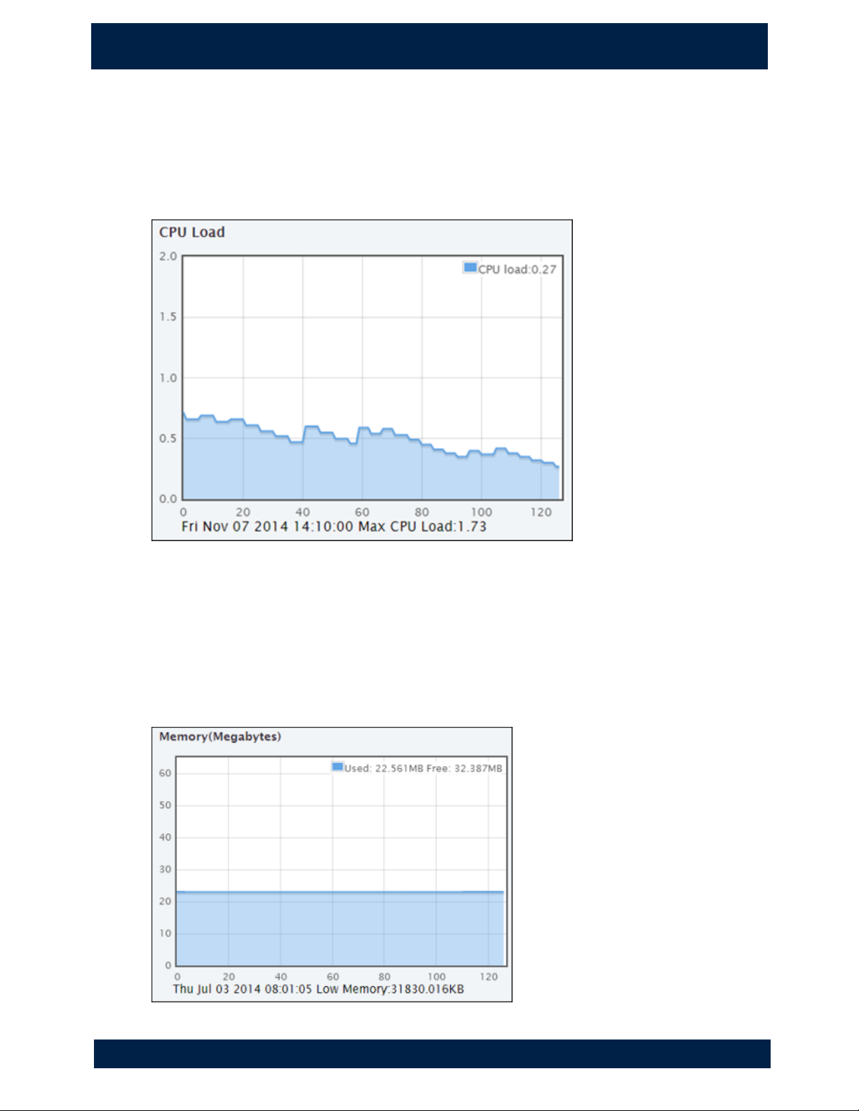
CPU Load
Legend shows the current CPU load. This value represents the number of processes
waiting in queue; in a healthy environment, CPU load should not be consistently above
1.0.
Graph provides an overview of the historical CPU load.
Memory (Megabytes)
Legend shows the current memory usage, allowing you to visualize available memory.
Graph provides an overview of historical memory usage. A flat line with few peaks and
valleys is normal in a healthy system. If memory usage keeps increasing, this may cause
system instability. If this occurs, note the used and free values in the legend and call
system support.
Page 15
2 . S Y S TE M P AG E
S y s t e m > Pe r f or m a nc e
9
NVT P h y b r id g e CL E E R S w i t ch U se r G u id e
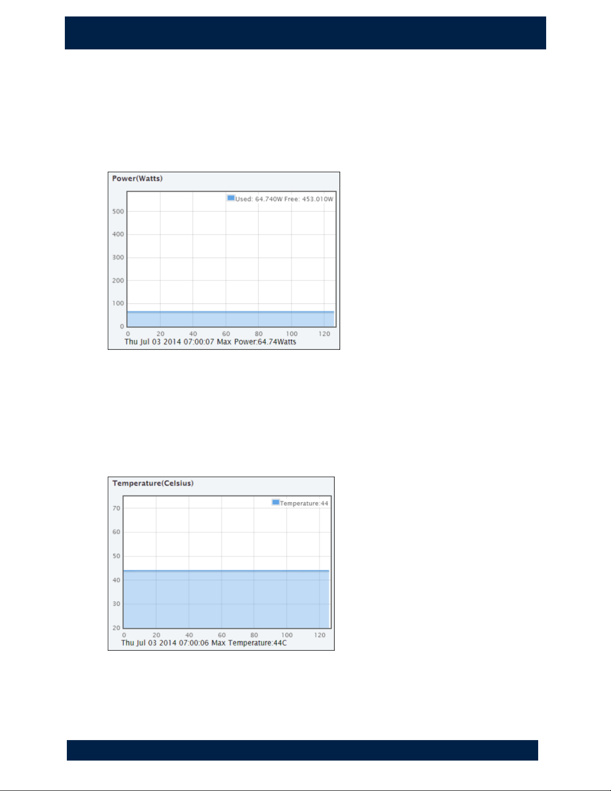
Power (Watts)
Legend shows the current total power consumption. Use the legend to identify the free
power availability and manage it accordingly.
Graph provides an overview of the historical total power consumed by the switch and all
devices connected to it. Expect variations as activities on the switch change. Peaks and
valleys are normal as devices are added and removed.
Temperature (Celsius)
Legend shows the current switch temperature.
Graph provides an overview of the historical switch temperature. A flatline with few
peaks and valleys is normal in a healthy system as long as the temperature remains
below 55. If the temperature remains above 55, observe the physical switch
environment to ensure proper ventilation and cooling.
Page 16
10
2 . S Y S TE M P AG E
S y s t e m> Lo g
NVT P h y b r id g e CL E E R S w i t ch U se r G u id e
System> Log
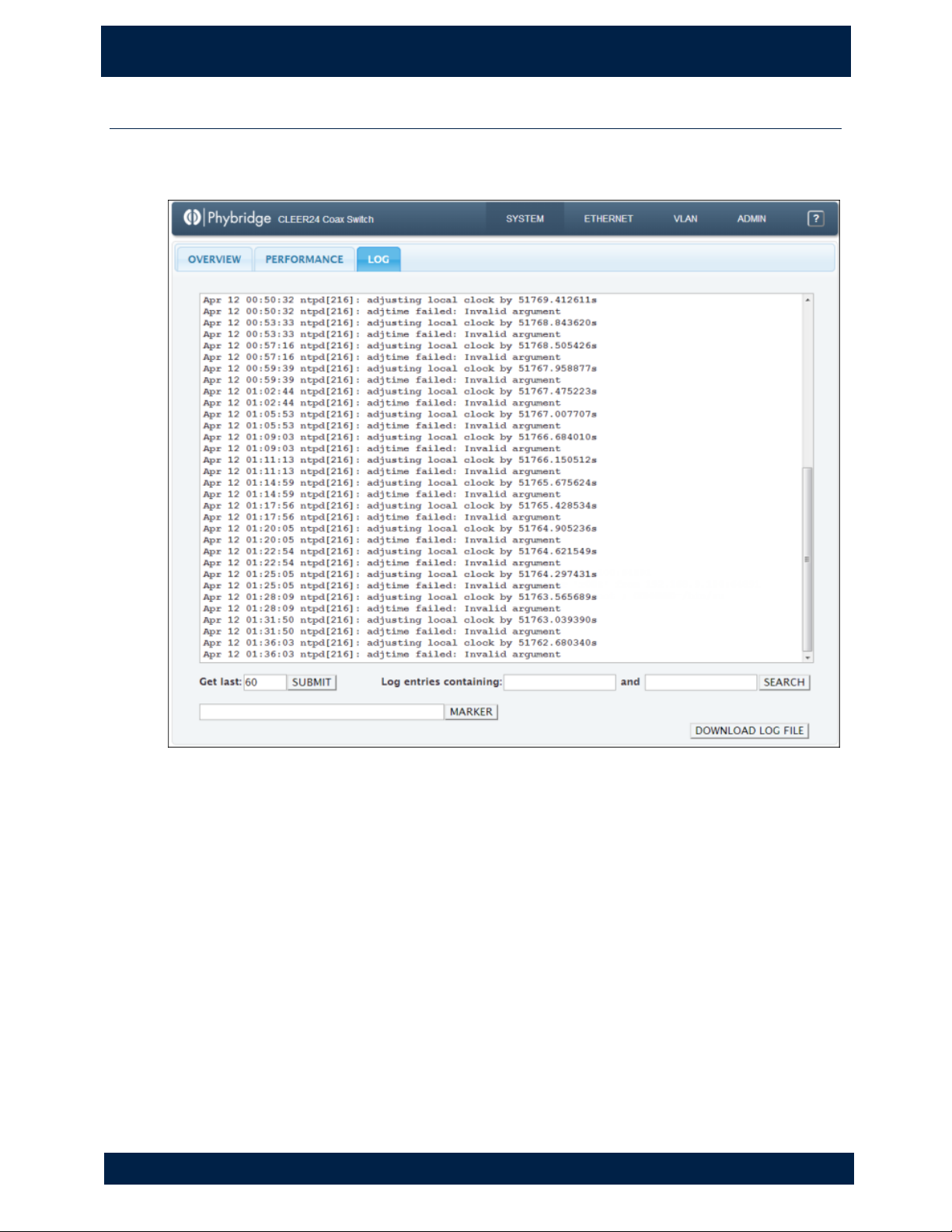
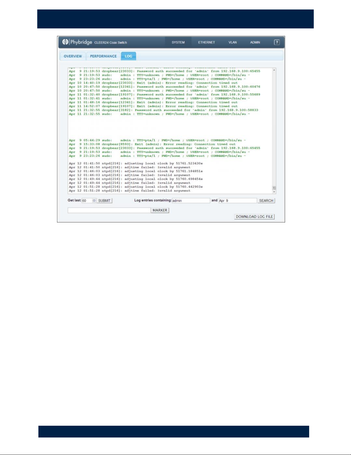
Use to view the system log with real-time updates. You can also add markers to the log
and download the log file.
Selecting the number of events to display
1. In the Get last list, select the number of events to display on the Log tab. You can
enter a value or use the arrows to increase/decrease the value in increments of
10.
2. Click SUBMIT. The Log tab is updated immediately .
Searching Log entries
1. You can enter multiple search terms in the “Log entries containing” window.
Search terms are case sensitive and spaces are significant.
2. Click SEARCH. The Log tab is updated immediately.
3. Search results are shown in green text and the log entries are in black.
Page 17
2 . S Y S TE M P AG E
S y s t e m> Lo g
11
NVT P h y b r id g e CL E E R S w i t ch U se r G u id e
Adding markers to the log
You can add markers to mark particular points in the log. For example, you could use
markers to mark the start and end points of certain events you would like to monitor.
Markers are added to the log shown on the Log tab and also to the log stored on the
remote log server.
1. Enter the marker text.
2. Click MARKER. The marker is added to the log.
Downloading the log file
Click DOWNLOAD LOG FILE to save a copy of the log file shown on the Log tab. The
filename for the exported file uses the convention <hostname>.log (example:
switch.log). This allows you to easily identify which switch the file was exported from.
NOTE
You can continue using the Simple Network Manager while the file is downloading. When
the file download is complete, the file should be shown in the bottom-left corner of
your browser (Chrome) or in the Downloads window (Firefox). Double-click the file to
open it.
Page 18
3 . E T H ER N E T P A G E
A b o u t t h e E t h er n e t P ag e
12
N V T P hy b r id g e C LE E R Sw i t ch U s er G u i de
3. E th erne t Pa ge
About the Ethernet Page
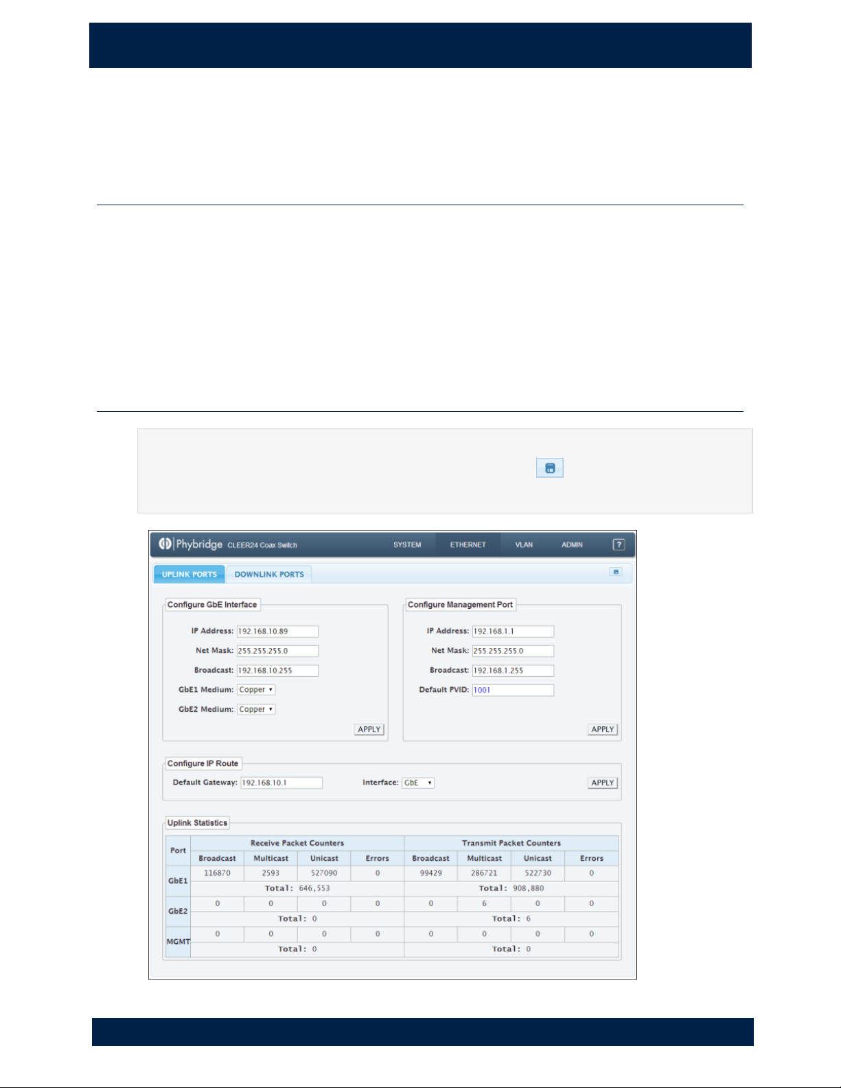
The Ethernet page allows you to monitor the health of the network, configure the switch
network interface, and manage uplink and downlink ports.
The Ethernet page contains three tabs:
• Uplink Ports
• Downlink Ports
• PoE Ports
Ethernet > Uplink Ports
IMPORTANT
Changes that you apply are temporary. If you do not click to save changes, any
changes made on this tab will be lost after a system reboot.
Page 19
3 . E T H ER N E T P A G E
E t h e r ne t > U p li n k P o r ts
13
NVT P h y b r id g e CL E E R S w i t ch U se r G u id e
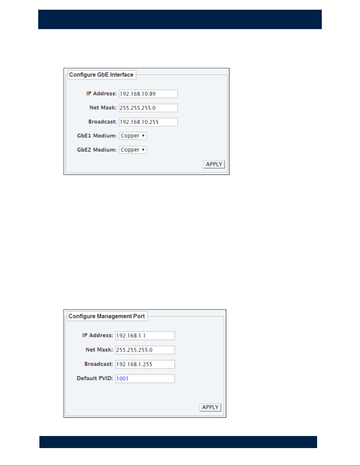
Configure GbE Interface
Use to configure the switch network interface.
1. Modify any of the fields (IP Address, Net Mask, Broadcast, GbE1 Medium, GbE2
Medium).
Notes:
• If the IP address is changed, the new IP address will be required to log back
into the box.
• The management port IP address and the uplink port IP address should
never be on the same subnet. This ensures the management port can still
be reached if the data LAN experiences issues.
2. Click APPLY.
Configure Management Port
Use to configure the management port IP address.
Page 20
14
3 . E T H ER N E T P A G E
E t h e r ne t > U p li n k P o r ts
NVT P h y b r id g e CL E E R S w i t ch U se r G u id e
1. Modify any of the fields (IP Address, Net Mask, Broadcast, Default PVID).
Notes:
• If the IP address is changed, the new IP address will be required to log back
into the box via the management port.
• The management port IP address and the uplink port IP address should
never be on the same subnet. This ensures the management port can still
be reached if the data LAN experiences issues.
• The default PVID (which is the default VLAN ID for the management port)
can be changed using the command line interface in Admin > Terminal (see
page 31).
2. Click APPLY.
Configure IP Route
Use to configure the default gateway IP address and to select the interface to apply it to.
1. Modify any of the fields (Default Gateway, Interface).
Notes:
• The Default Gateway can be assigned to only one interface. The interface
can be either GbE or Mgmt.
• If the IP address is changed, the new IP address will be required to log back
into the box via the management port.
• The management port IP address and the uplink port IP address should
never be on the same subnet. This ensures the management port can still
be reached if the data LAN experiences issues.
2. Click APPLY.
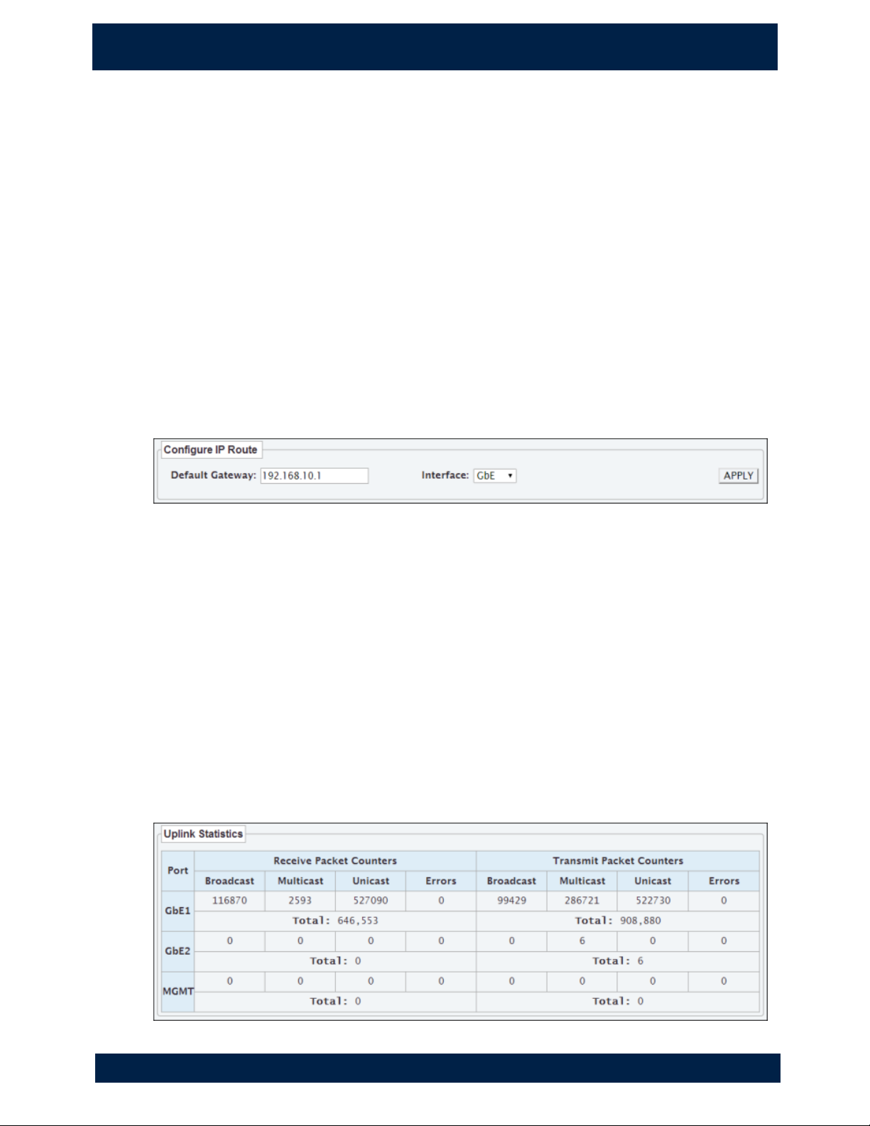
Viewing Uplink Statistics
Displays a breakdown of packets received to and transmitted from the LAN ports.
Page 21
3 . E T H ER N E T P A GE
E t h e r ne t > D ow n l in k Po r t s
15
NVT P h y b r id g e CL E E R S w i t ch U se r G u id e
Ethernet > Downlink Ports
IMPORTANT
Changes that you apply are temporary. If you do not click to save changes, any
changes made on this tab will be lost after a system reboot.
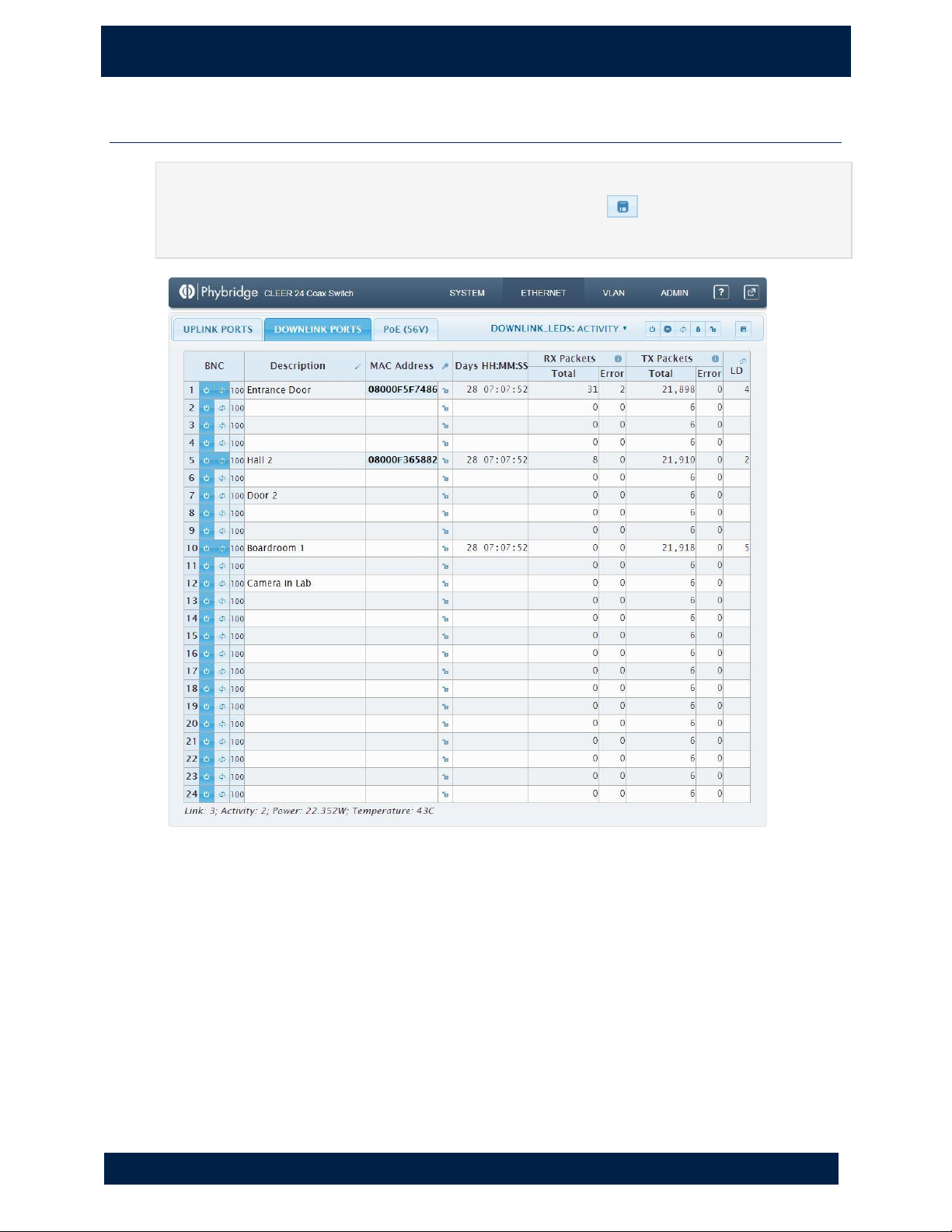
Ports 1-24
Used to manage the downlink ports.
Viewing adapter information
Adapter summary information is shown below the port details table and includes the
number of adapters connected, the number of endpoints connected to the adapters, the
total power being consumed, and the temperature of the switch. This information is
updated in real-time.
Page 22

16
3 . E T H ER N E T P A G E
E t h e r ne t > D ow n l in k Po r t s
NVT P h y b r id g e CL E E R S w i t ch U se r G u id e
Viewing port information
The following information is shown for each port:
BNC
Port number. Double-click to view ethernet statistics for the port. These
statistics include non-zero data only (does not include inactive).
Control power to the port. Click to turn the power on or off. Dark blue =
on, light blue = off.
or
Click or at the top right of the tab to turn all ports on or off.
Indicates the link status. Dark blue = linked, light blue = not linked. Click
to reset the port.
or
Click at the top right of the tab to reset all ports at once.
Description
Description of the port for easy identification on the System > Overview
page; click on a description to edit it. The Description is shown in blue
text while editing.
NOTE: Remember to hit Enter to save any changes.
or
Indicates whether a read-only link exists between the adapter and the
switch. Click to lock or unlock MAC address to the port.
or
Click or at the top right of the tab to lock/unlock all ports at
once.
Page 23
3 . E T H ER N E T P A G E
E t h e r ne t > D ow n l in k Po r t s
17
NVT P h y b r id g e CL E E R S w i t ch U se r G u id e
MAC Address
MAC address of the IP device connected to the adapter associated with this
port.
Days
HH:MM:SS
Length of time the device has been connected to the adapter.
RX Packets
TX Packets
Number of packets received and transmitted from this port, and number
of errors, captured in real-time and updated approximately every second.
Error counts should be low in comparison to the number of packets. Any
negative values should be interpreted as zero. Hover over the Total to see
a breakdown of Multicast, Broadcast, and Unicast packets.
LD
Number of link-down events (these occur when the adapter goes through
a link transition). A high number may indicate physical errors. Doubleclick to view link transition statistics for the port. This historical
information can help you to identify patterns of downtime (e.g. frequency,
consistent time, duration, etc.).
Downloading the MAC address table
You can download a CSV file containing the MAC address table for the switch.
1. Click at the top right of the tab to download the MAC address table. The
filename for the exported file uses the convention <hostname>.csv (example:
switch.csv). This allows you to easily identify which switch the file was exported
from.
2. When the file download is complete, the file should be shown in the bottom-left
corner of your browser (Chrome) or in the Downloads window (Firefox). Doubleclick the file to open it.
Page 24
4 . V L AN P A GE
A b o u t t h e V L AN P ag e
18
N V T P hy b r id g e C LE E R Sw i t ch U s er G u i de
4. V LAN Page
About the VLAN Page
The VLAN page simplifies the management of VLANs, reducing the potential for error.
The VLAN page contains three tabs:
• VLAN TABLE
• VLAN to PORT
• ASSIGN PVID
VLAN > VLAN Table
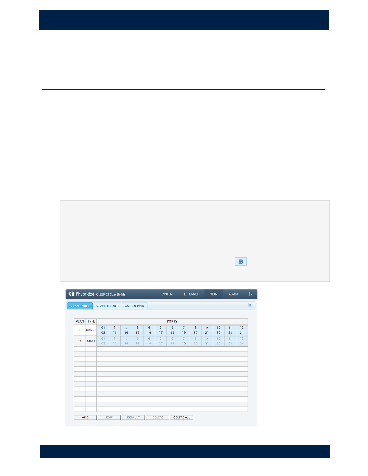
Use to add or delete a VLAN or to change the default VLAN. For each VLAN, the VLAN
number, type and ports are shown.
IMPORTANT
Do not use VLAN 0. There is potential in the VLAN specification to interpret the standard
for VLAN 0 in different ways, which can lead to incompatibility between different vendor
units.
IMPORTANT
Changes that you apply are temporary. If you do not click to save changes, any
changes made on this tab will be lost after a system reboot.
Page 25

4 . V L AN P A GE
V L A N > V LA N Ta b l e
19
NVT P h y b r id g e CL E E R S w i t ch U se r G u id e
NOTE
WHITE BACKGROUND — Port is not a member.
BLUE BACKGROUND — Port is a member.
BLACK TEXT — Port is a PVID.
GREY TEXT — Port is only a member of the VLAN.
Adding a VLAN
You can add a new static VLAN.
1. Click ADD.
2. Enter the VLAN number and click OK.
3. Click to save your changes.
4. To assign ports to the VLAN, click the VLAN and click EDIT.
The VLAN to PORT tab appears with the VLAN panel open. You can now assign ports to the VLAN
(see "VLAN > VLAN To Port" on page 22).
Editing a VLAN
1. Click a VLAN. The selected VLAN will now be enclosed in a black border.
2. Click EDIT.
The VLAN to PORT tab appears with the VLAN panel open. You can now assign ports to the VLAN
(see "VLAN > VLAN To Port" on page 22).
Setting the default VLAN
The default VLAN is used for ports not assigned to any other VLAN. VLAN 1 is the
system default; however, you can select a different default VLAN if desired.
1. Click the VLAN you want to set as the default.
2. Click DEFAULT.
3. Click to save your changes.
Deleting VLANs
You can delete a static VLAN; you cannot delete the default VLAN.
1. Click the VLAN you want to delete, then click DELETE.
or
Click DELETE ALL to delete all static VLANS.
2. Click to save your changes.
Page 26
20
4 . V L AN P A GE
V L A N > V LA N To P or t
NVT P h y b r id g e CL E E R S w i t ch U se r G u id e
VLAN > VLAN To Port
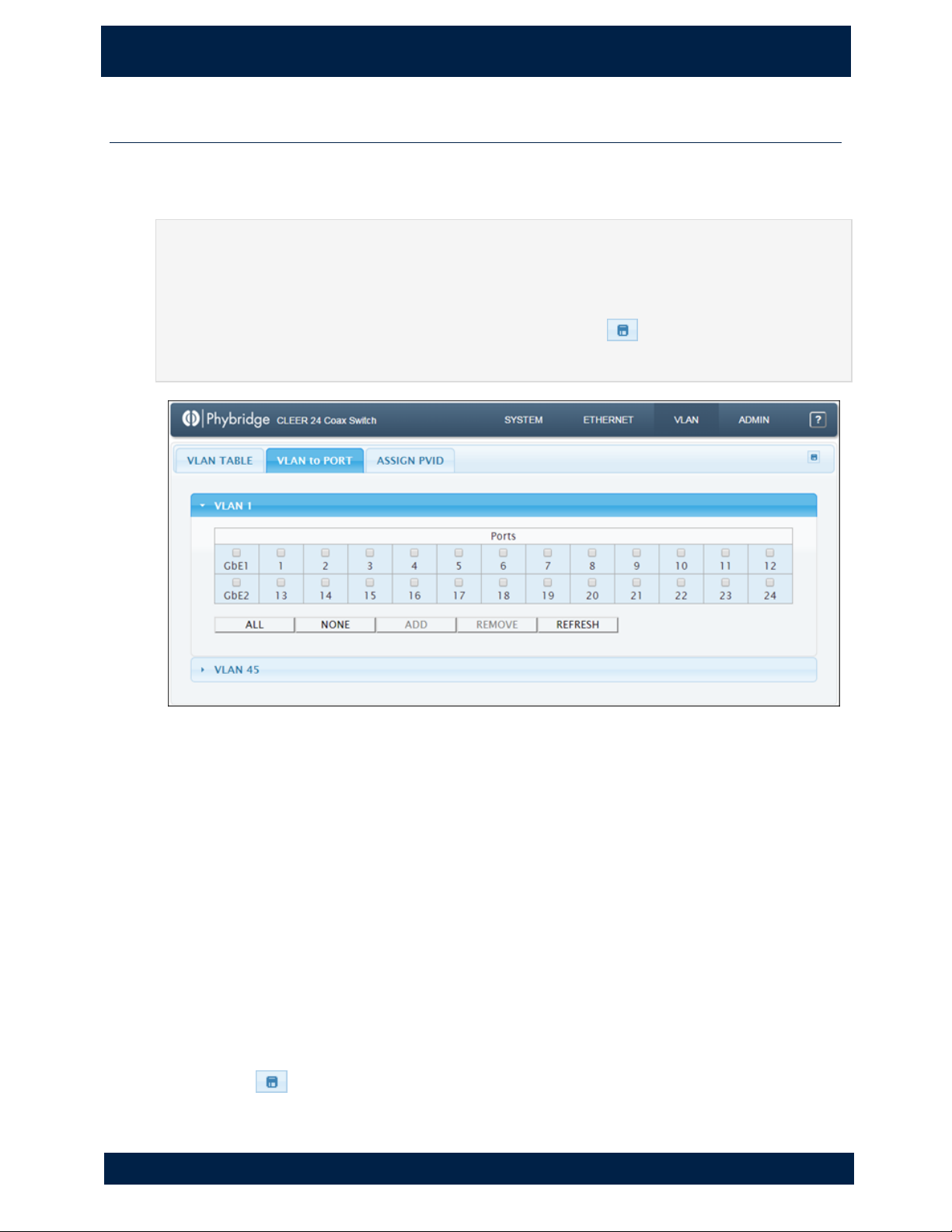
Use to assign ports to VLANs. You can add/remove individual ports from a VLAN or you
can add/remove all ports at once.
NOTE
Use the VLAN Table tab to create and remove VLANs (see page 20).
IMPORTANT
Changes that you apply are temporary. If you do not click to save changes, any
changes made on this tab will be lost after a system reboot.
Viewing VLAN port details
Each VLAN is shown as a separate panel.
1. Click the panel header (the VLAN number) to expand the panel.
2. A table with all ports is shown. The ports that are members of the VLAN have a
shaded background. Ports that are not members have a white background.
Assigning ports to a VLAN
1. Click one or more ports in the VLAN panel.
or
Click ALL to select all ports. (Click NONE to clear all ports.)
A checkmark is shown on selected ports.
2. Click ADD. The added ports now have a shaded background.
3. Click to save your changes.
Page 27
4 . V L AN P A GE
V L A N > A s si g n P V ID
21
NVT P h y b r id g e CL E E R S w i t ch U se r G u id e
Removing ports from a VLAN
1. Click one or more ports in the VLAN panel.
or
Click ALL to select all ports. (Click NONE to clear all ports.)
A checkmark is shown on selected ports.
2. Click REMOVE. The removed ports now have a white background.
3. Click to save your changes.
Refreshing VLAN information
VLAN information on this tab is not updated in real-time. Click REFRESH to update the
information (for example, to see any changes made by other users).
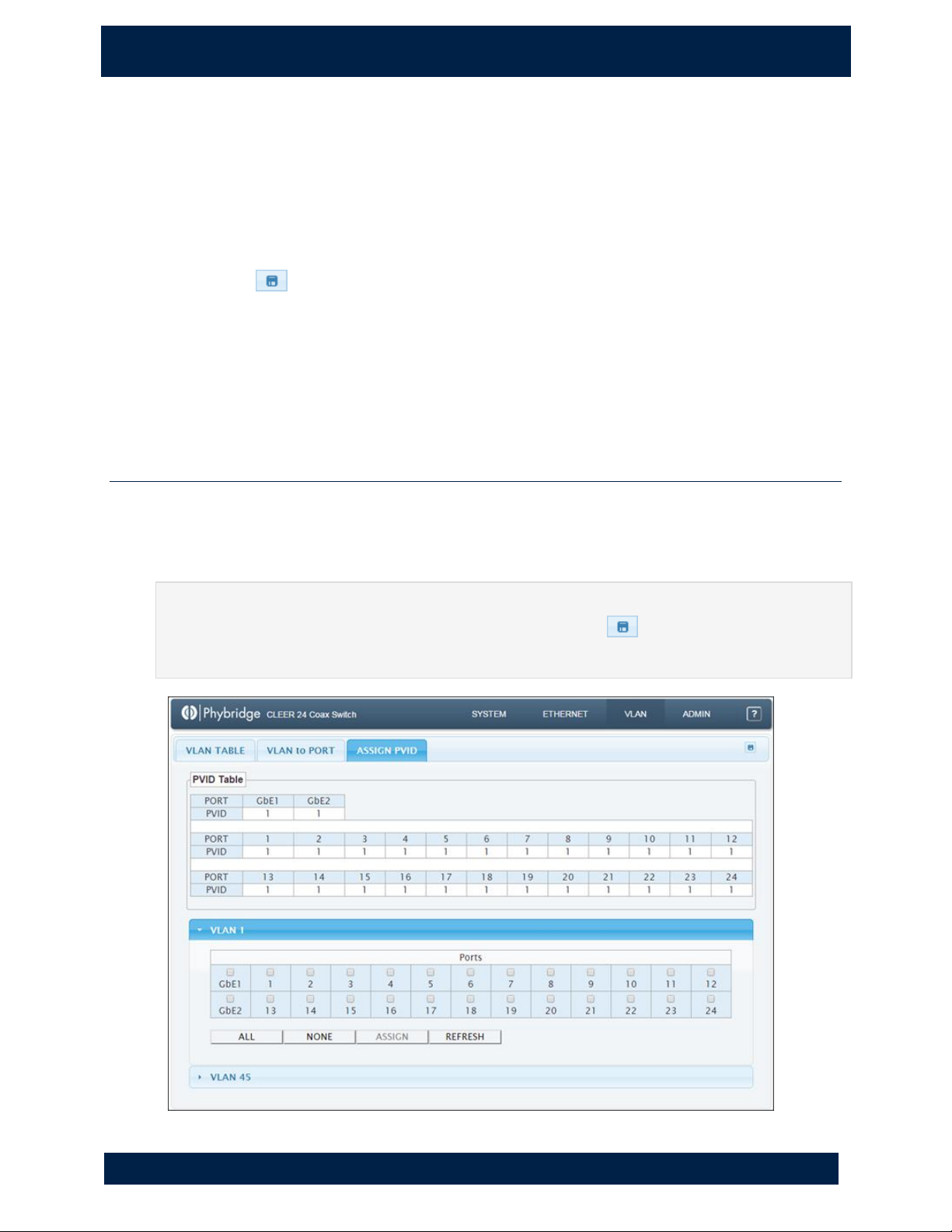
VLAN > Assign PVID
Use to assign the primary VLAN ID to ports. VLANs created in the VLAN Table tab can be
used for PVID tagging. For details on adding and removing VLANs, see "VLAN > VLAN
Table" on page 20.
IMPORTANT
Changes that you apply are temporary. If you do not click to save changes, any
changes made on this tab will be lost after a system reboot.
Page 28

22
4 . V L AN P A GE
V L A N > A s si g n P V ID
NVT P h y b r id g e CL E E R S w i t ch U se r G u id e
PVID Table
Static panel showing each port's PVID. Each port has only one PVID. By default, every
port is assigned the system default VLAN as the PVID. (The default VLAN is set on the
VLAN Table tab; see page 20)
Viewing port PVID details for a VLAN
Each VLAN is shown as a separate panel.
1. Click the panel header (the VLAN number) to expand the panel.
2. A table with all ports is shown. The ports that belong to the PVID have a shaded
background. Ports that do not belong to the PVID have a white background.
Adding or modifying a port PVID
IMPORTANT
The switch may lose connectivity if you change the PVID of the GbE ports. Use caution
when considering making changes to these ports.
1. Click one or more ports in the VLAN panel.
or
Click ALL to select all ports, with the exception of GbE1 and GbE2. (Click NONE to clear all ports.)
A checkmark is shown on selected ports.
2. Click ASSIGN. The new PVID is established and the added ports now have a shaded
background.
3. Click to save your changes.
Refreshing VLAN information
VLAN information on this tab is not updated in real-time. Click REFRESH to update the
information (for example, to see any changes made by other users).
Page 29
5 . A D MI N P AG E
A b o u t t h e A d mi n P ag e
23
N V T P hy b r id g e C LE E R Sw i t ch U s er G u i de
5. A dm in P ag e
About the Admin Page
The Admin page allows you to configure switch settings, control services, configure
servers, and use the command line interface.
The Admin page contains three tabs:
• Setup
• Services
• Terminal
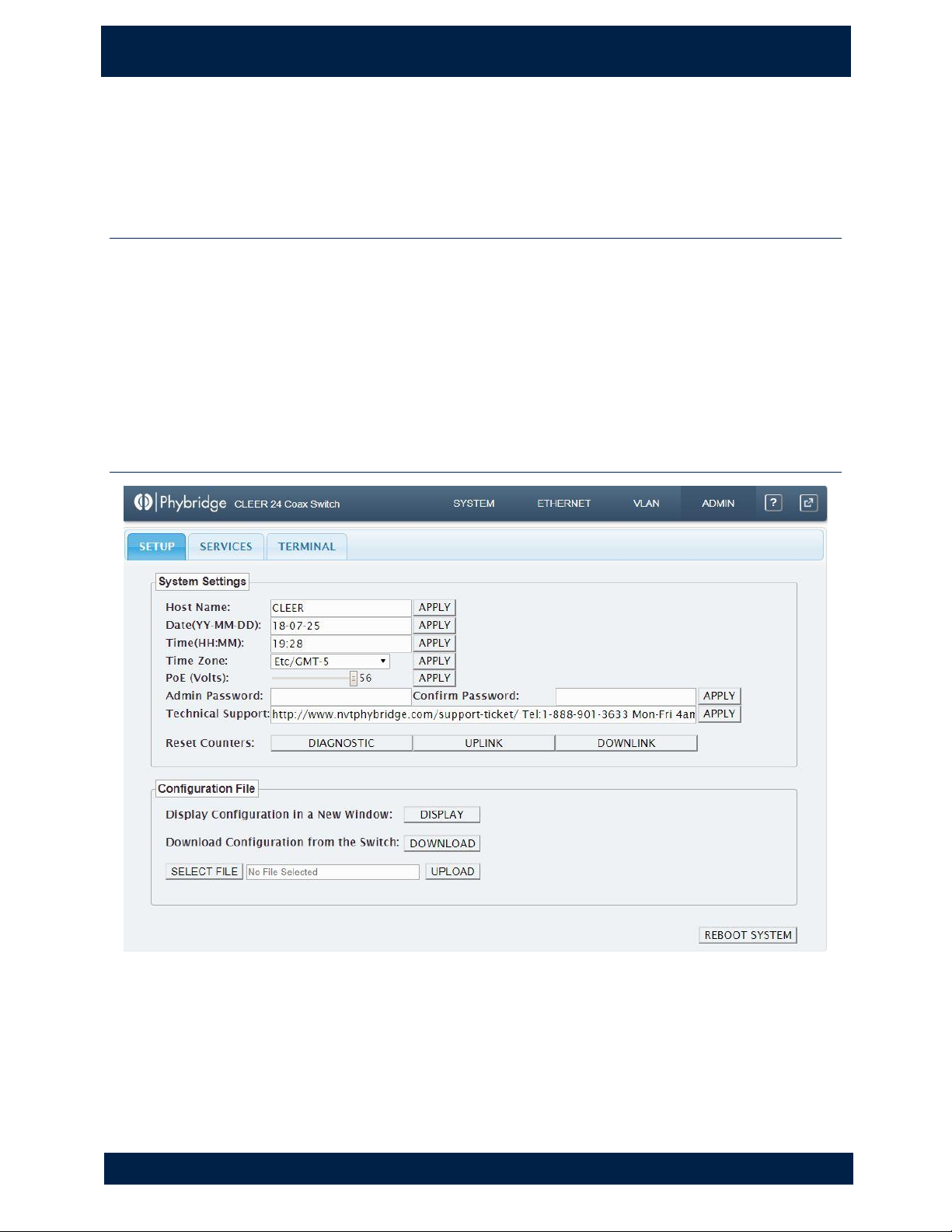
Admin > Setup
Page 30
24
5 . A D MI N P AG E
A d m i n > S et u p
NVT P h y b r id g e CL E E R S w i t ch U se r G u id e
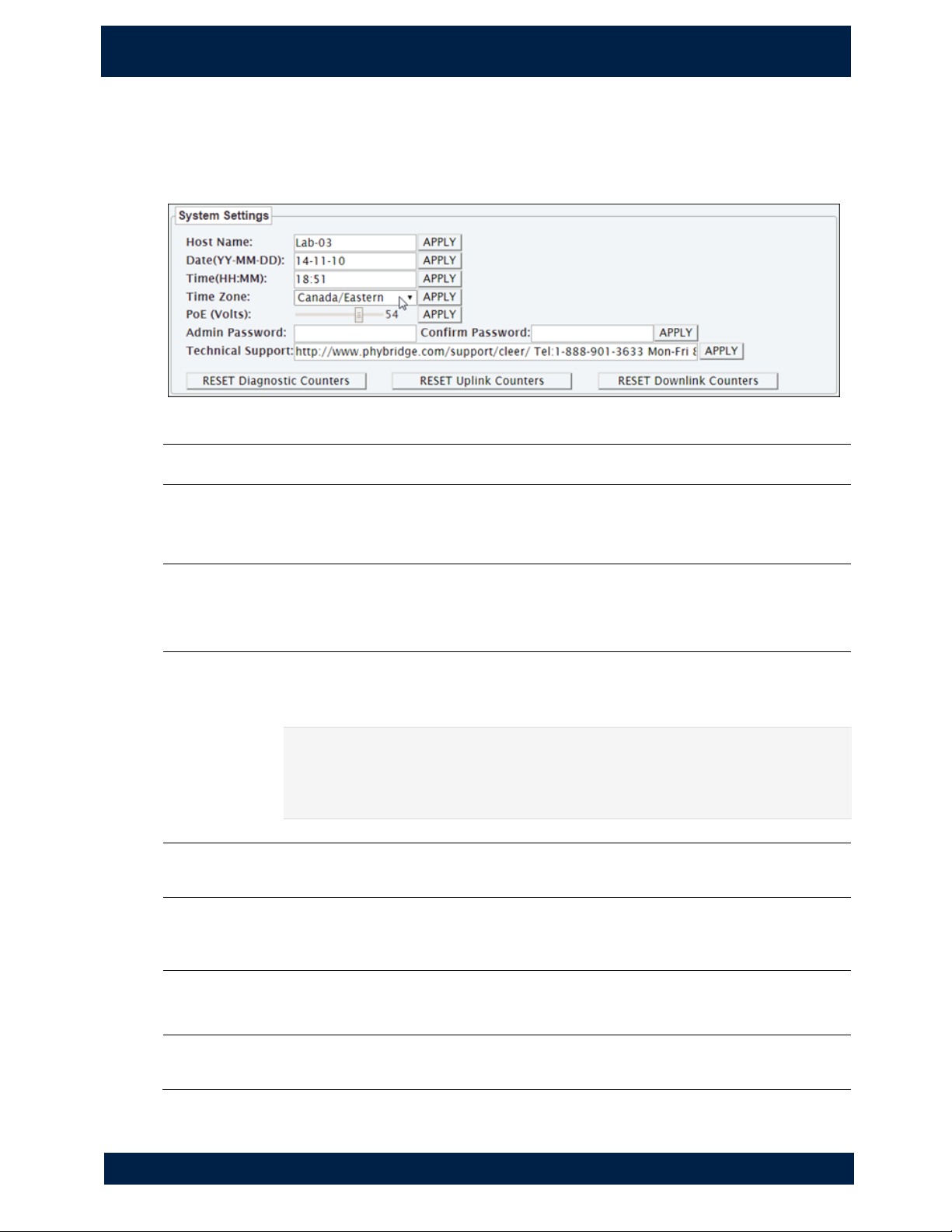
System Settings
Use to configure basic switch settings. After modifying a setting, click APPLY. The
updates will be applied immediately to the switch.
Host Name
Switch host name.
Date
Time
Time Zone
Switch date (YY-MM-DD), time (HH:MM), and time zone.
PoE Voltage
Adjust the power available to the device connected. Defaults to 56V
which is the recommended voltage for PoE. Range from 48 – 56V; use
slider to adjust. Click APPLY.
Admin
Password
Confirm
Password
Simple Network Manager password. To change the password, enter the
new password in both of these fields, then click APPLY.
NOTE
You will be prompted to log back into the Simple Network Manager after
changing the password.
Technical
Support
Technical Support contact information.
Reset
Diagnostic
Counters
Reset only the diagnostic counters.
Reset Uplink
Counters
Reset all counters for the gigabit ports (transmit/receive counts, errors,
broadcasts, and multicasts).
Reset Downlink
Counters
Reset all downlink counters (transmit/receive counts and errors).
Page 31
5 . A D MI N P AG E
A d m i n > S et u p
25
NVT P h y b r id g e CL E E R S w i t ch U se r G u id e
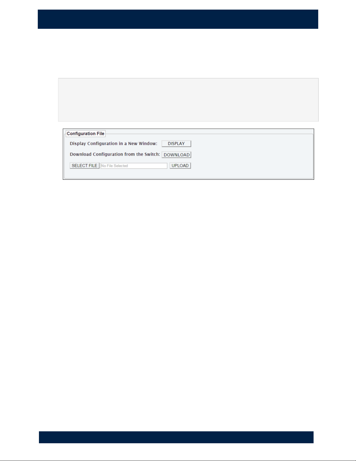
Import/Export Configuration
You can import or export the current switch configuration. This allows you to download
the existing configuration, make changes, and then upload the new configuration.
IMPORTANT
When editing the configuration file, the existing syntax must be strictly followed or you
may lose access to the switch. The file must be saved in Unix file format; using a
program such as dos2unix/unix2dos or Notepad++ to edit the file is recommended.
View the switch configuration
To view the current switch configuration, click DISPLAY. You can copy the text from this
window to paste into another application or document.
Export configuration from the switch
1. Click DOWNLOAD to save a copy of the current switch configuration.
The filename for the exported file uses the convention <hostname>.cfg (example: switch.cfg). This
allows you to easily identify which switch the file was exported from.
2. When the file download is complete, the file should be shown in the bottom-left
corner of your browser (Chrome) or in the Downloads window (Firefox). Doubleclick the file to open it.
3. You can modify the following settings in the configuration file:
• switch host name and IP address
• information for the NTP Server, SNMP Service, Syslog Server, and VLAN, and
Port Enable/Disable
Import configuration to the switch
1. To import or upload the modified configuration file to the switch, click SELECT
FILE and select the configuration file to upload.
2. Verify that you have selected the correct file and click UPLOAD. When the upload
is complete, the configuration changes are applied immediately to the switch.
Page 32
26
5 . A D MI N P AG E
A d m i n > S er v i ce s
NVT P h y b r id g e CL E E R S w i t ch U se r G u id e
Admin > Services
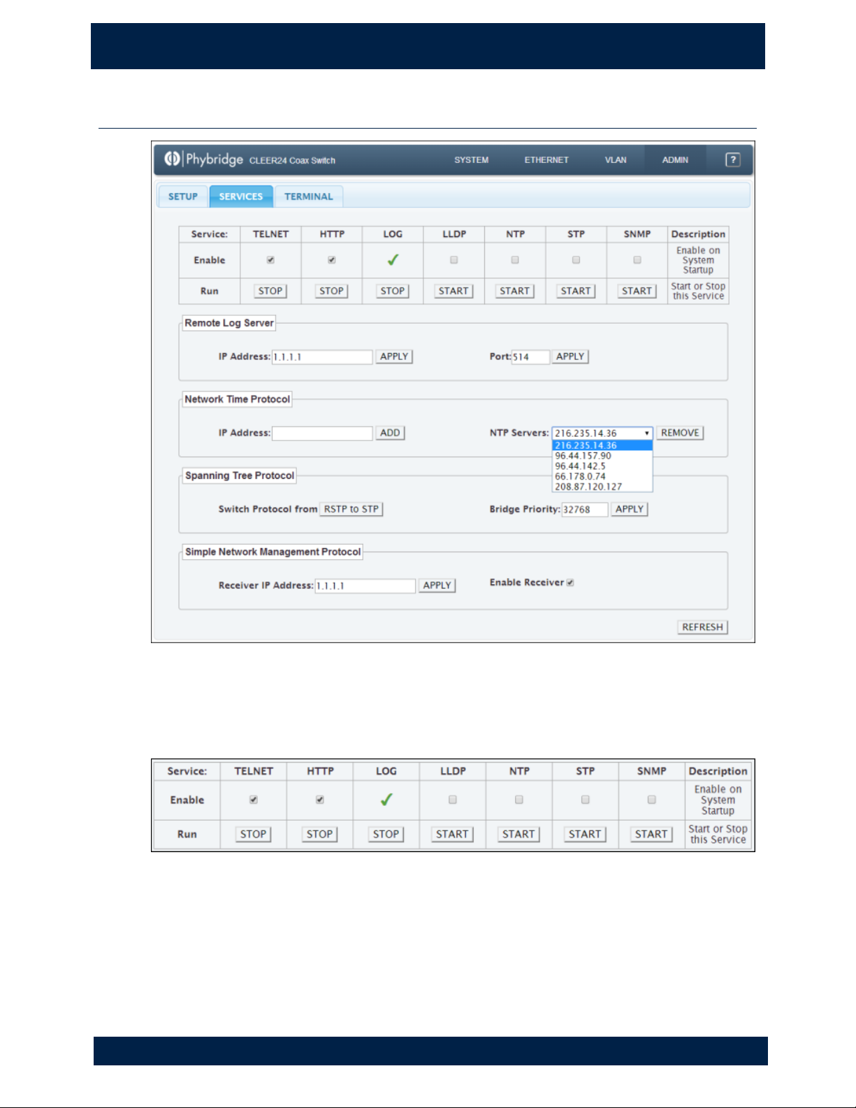
Services
Use to control all the services for the switch including TELNET, HTTP, LOG, LLDP, NTP,
STP and SNMP.
Page 33
5 . A D MI N P AG E
A d m i n > S er v i ce s
27
NVT P h y b r id g e CL E E R S w i t ch U se r G u id e
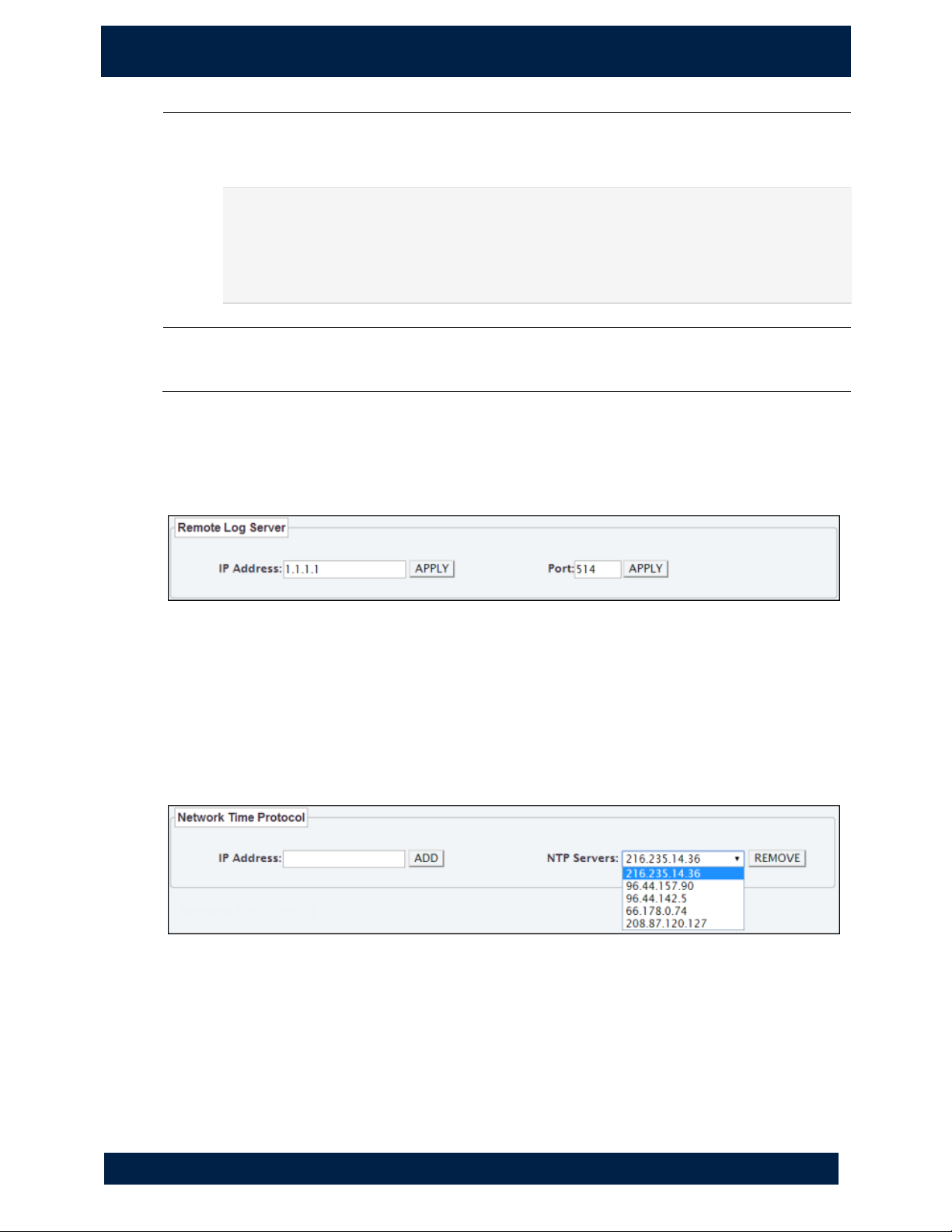
Enable
Click to enable/disable a service. This determines whether the service is enabled
or disabled on system startup. The Log service is always enabled.
IMPORTANT
If you disable the HTTP service, the Simple Network Manager will not function
after a reboot. If you stop the HTTP service, you will instantly lose connectivity
to the Simple Network Manager.
Run
Click to start or stop a service. Note that the start or shutdown of services is not
instantaneous and may take up to one minute.
Remote Log Server
Use to set up a remote log server. Changes are applied immediately.
1. Enter the IP address of the remote log server and click APPLY.
2. (Optional) Change the port number and click APPLY. The default port number is
514.
Network Time Protocol
Use to configure multiple NTP servers.
1. To add a server, enter the IP address and click ADD.
2. To remove a server, select a server from the list and click REMOVE.
Page 34
28
5 . A D MI N P AG E
A d m i n > S er v i ce s
NVT P h y b r id g e CL E E R S w i t ch U se r G u id e
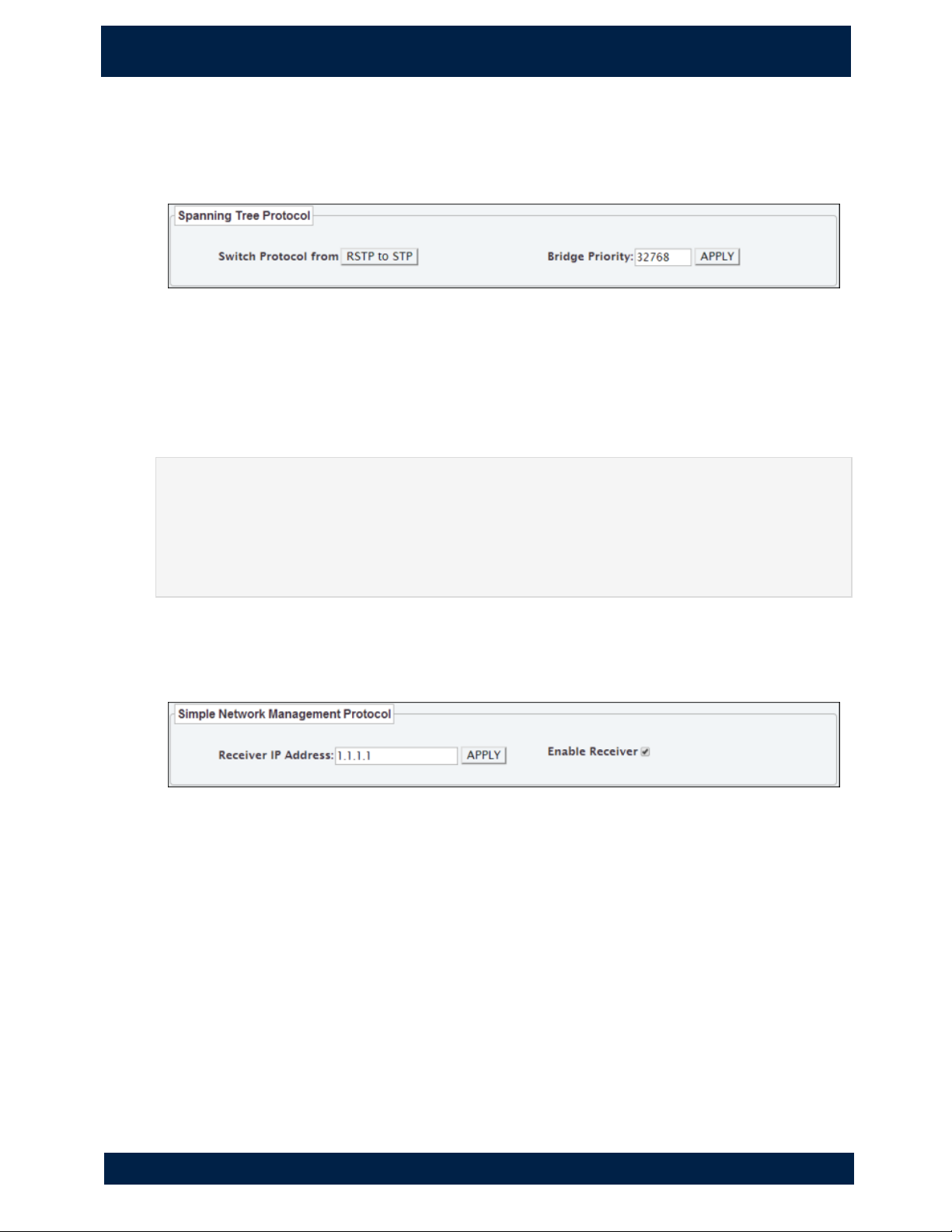
Spanning Tree Protocol
Use to change the spanning tree protocol. The switch supports classic STP and RSTP
(rapid spanning tree protocol); the default is RSTP.
1. To change the protocol, click the Switch Protocol button.
The button name changes based on the currently selected protocol. For example, if the current
protocol is RSTP, the option "Switch Protocol from RSTP to STP" will be shown.
2. To change the bridge priority, use the up and down arrows to increase/decrease
the priority in increments of 4096, then click APPLY.
CAUTION
Enabling STP in a live network will cause service disruptions to end users while the
network is converging. To avoid impacting users, enabling of STP should be conducted
outside of core hours or during a scheduled maintenance period. Consult the MCD
Resiliency Guidelines for information on how to optimally configure STP/RSTP.
Simple Network Management Protocol
Use to modify the simple network management protocol.
1. To change the receiver IP address, enter the address and click APPLY.
2. To enable/disable the receiver, click the Enable Receiver checkbox.
Page 35
5 . A D MI N P AG E
A d m i n > T er m i na l
29
NVT P h y b r id g e CL E E R S w i t ch U se r G u id e
Admin > Terminal
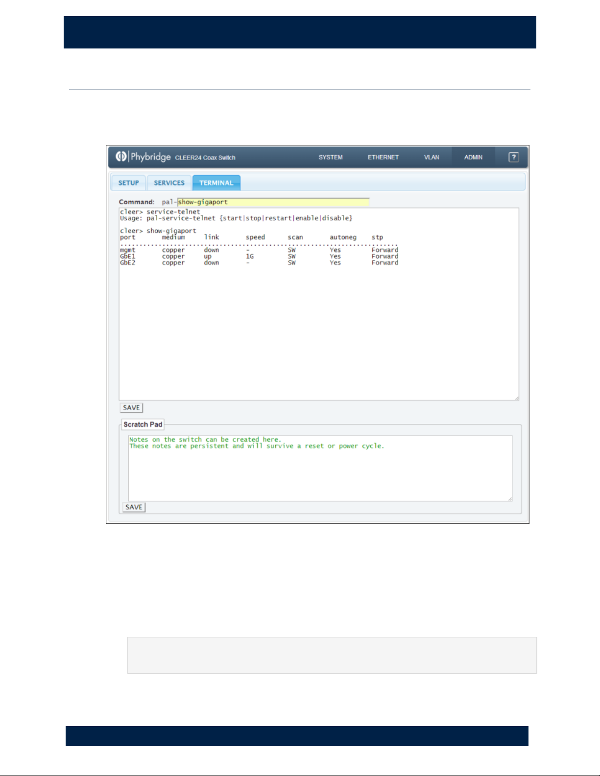
The Terminal tab provides you with a command line interface you can use to configure
the switch and diagnose switch issues. You can also use this tab to add notes to the
switch.
Using the Command Line Interface
1. Double-click in the Command field to see a list of available commands, or type
the first few characters of a command to filter the list.
2. Click a command in the list to select it.
3. If necessary, enter any options for the command.
NOTE
See "Command Reference" on page 33 for a list of command options and syntax.
4. Press ENTER to run the command.
Page 36

30
5 . A D MI N P AG E
A d m i n > T er m i na l
NVT P h y b r id g e CL E E R S w i t ch U se r G u id e
The results of the command appear in the area below the command. When a new
command is run, the results are appended to the results from the previous command.
You can now do the following:
• Modify the text in the results area (make changes, delete text, add comments,
copy and paste, etc.). Right-click in the results area to view editing options such
as copy, paste and spell-check.
• Click SAVE to save the results in a text file. When the file download is complete,
the file should be shown in the bottom-left corner of your browser (Chrome) or in
the Downloads window (Firefox). Double-click the file to open it. The filename for
the exported file uses the convention hostname_terminal_date_time.txt. This
allows you to easily identify which switch the file was exported from.
Adding notes to the switch
You can save notes on the switch. These notes are seen by all operators with access to
the Simple Network Manager.
1. Type a note in Scratch Pad area. You can modify the note the same way you can
modify the command results (make changes, delete text, add comments, copy and
paste, etc.). Right-click in the Scratch Pad area to view editing options such as
copy, paste and spell-check.
2. Click SAVE.
Page 37

6 . C O MM A N D L I N E I N T E RF A CE
C o m m a nd Re f er e n c e
31
N V T P hy b r id g e C LE E R Sw i t ch U s er G u i de
6. C ommand L in e In te rf ac e
Command Reference
The following commands can be used in the command line interface in Admin >
Terminal (see page 31).
Notes:
• Commands must be entered exactly as shown in the Usage column.
• <> denote single-value entries of a specific item, as explained within the
brackets.
• { } denote a set or list or range of entries for a specific item.
• [ ] denote an optional entry.
• If you enter a command using incorrect syntax, the correct syntax will be shown.
• If you enter incorrect values for a command, you will receive a message stating
that the values are not within the acceptable range.
Command
Purpose
Usage
Usage Notes
pal
Main interface
for PAL.
pal help
{cmd|short|long|configure|examine|persisten
t}
pal-conf-edit
Modify user
persistent
configuration.
pal-conf-edit {show|clear}
pal-conf-edit delete<LINENUMBER>
<LINENUMBER>
is a single-value
entry of the line
number you wish
to delete.
pal-conf-export
Export/import
persistent user
configuration
into/from
tmp/switch.cfg.
pal-conf-export {export|import}
pal-conf-save
Save the
configuration of
the switch.
pal-conf-save
Page 38

32
6 . C O MM A N D L I N E I N T E RF A CE
C o m m a nd Re f er e n c e
NVT P h y b r id g e CL E E R S w i t ch U se r G u id e
Command
Purpose
Usage
Usage Notes
pal-service-http
Enable or
disable HTTP
service on the
switch.
pal-service-http-https
{start|stop|restart|enable|disable}
pal-service-lldp
Enable or
disable LLDP
service on the
switch.
pal-service-lldp
{start|stop|restart|show|enable|disable}
pal-service-lldpshow {1-24|all}
pal-service-log
Configure,
enable or
disable LOG
service on the
switch.
pal-service-log {start|stop|restart}
pal-service-log remote-syslog-show
pal-service-log remote-syslog-ip <IP>
pal-service-log remote-syslog-port <PORT>
<IP> is a single-
value entry of the
IP address of the
target syslog
server.
<PORT> is a
single-value
entry of the
syslog port
number on the
remote syslog
server. The
default is port
514.
NOTE
If you change the
syslog remote IP,
you are required
to restart the log
service.
pal-service-ntp
Enable or
disable NTP
service on the
switch.
pal-service-ntp
{start|stop|restart|enable|disable}
pal-service-snmp
Enable or
disable SNMP
service on the
switch.
pal-service-snmp
{start|stop|restart|enable|disable}
pal-service-snmp receiver
{enable|disable|show}
pal-service-snmp receiver-ip <ADDRESS>
Page 39

6 . C O MM A N D L I N E I N T E RF A C E
C o m m a nd Re f er e n c e
33
NVT P h y b r id g e CL E E R S w i t ch U se r G u id e
Command
Purpose
Usage
Usage Notes
pal-service-stp
Enable or
disable STP
service on the
switch.
pal-service-stp {GbE1|GbE2}
{enable|disable}
pal-service-stp service
{start|stop|enable|disable}
pal-service-stp proto {stp|rstp}
pal-service-stp port-priority <VALUE>
pal-service-stp showbridge
pal-service-stp showcfg {all|bridgepriority|protocol|age|forward-delay|GbE1cost|GbE2-cost}
pal-service-stp age <6-40>
pal-service-stp forward-delay <4-30>
pal-service-stp port-cost {GbE1|GbE2} <065536>
<VALUE> is a
single-value
entry of the
priority you wish
to assign. This
value ranges
from 0-61440
and can be
incremented by
4096. The default
is 32768.
pal-service-telnet
Enable or
disable telnet
service on the
switch.
pal-service-telnet
{start|stop|restart|enable|disable}
TACACS
Enable or
disable TACAS
AAA service on
the switch.
pal-service-security {show|tacacs}
pal-service-security tacacs
{show|enable|disable}
pal-service-security tacacs server1
<IP_ADDR|IP_ADDR:PORT|HOSTNAME|HOS
TNAME:PORT>
pal-service-security tacacs secret1 <STRING>
pal-service-security tacacs server2
<IP_ADDR|IP_ADDR:PORT|HOSTNAME|HOS
TNAME:PORT>
pal-service-security tacacs secret2 <STRING>
pal-service-security tacacs server3
<IP_ADDR|IP_ADDR:PORT|HOSTNAME|HOS
TNAME:PORT>
pal-service-security tacacs secret3 <STRING>
pal-service-security tacacs server4
<IP_ADDR|IP_ADDR:PORT|HOSTNAME|HOS
TNAME:PORT>
pal-service-security tacacs secret4 <STRING>
pal-service-security tacacs timeout
<SECONDS>
pal-service-security tacacs accounting
{on|off}
Page 40

34
6 . C O MM A N D L I N E I N T E RF A CE
C o m m a nd Re f er e n c e
NVT P h y b r id g e CL E E R S w i t ch U se r G u id e
Command
Purpose
Usage
Usage Notes
Radius
Enable or
disable Radius
service on the
switch.
pal-service-security {show|radius}
pal-service-security radius
{show|enable|disable}
pal-service-security radius server1
<IP_ADDR|IP_ADDR:PORT|HOSTNAME|HOS
TNAME:PORT>
pal-service-security radius secret1 <STRING>
pal-set-bridged
Switch between
managed and
unmanaged
modes.
pal-set-bridged {bridged/outband/disable}
Bridged Mode: All
network services
disabled and no
management via
ethernet.
Outband Mode:
All network
services on GbE
disabled.
Management
available via
MGMT port.
Disabled: Normal
operation.
pal-set-contact
Update the
point of contact
for the switch.
pal-set-contact <CONTACT>
<CONTACT> is a
single-value
entry of the
person’s name
that will be the
point of contact
for the switch.
Page 41

6 . C O MM A N D L I N E I N T E RF A C E
C o m m a nd Re f er e n c e
35
NVT P h y b r id g e CL E E R S w i t ch U se r G u id e
Command
Purpose
Usage
Usage Notes
pal-set-gigaport
Enable or
disable uplink
ports on the
switch; switch
between copper
and fiber
interfaces; add,
remove, and set
the default
VLAN of the
gigaports.
pal-set-gigaport {GbE1|GbE2|mgmt}
{enable|disable}
pal-set-gigaport {GbE1|GbE2} {copper|fiber}
pal-set-gigaport GbE add-vlan <VLANID>
{tagged|untagged}
pal-set-gigaport GbE remove-vlan <VLANID>
pal-set-gigaport GbE default-vlan <VLANID>
<VLANID> is a
single-value
entry of the
VLANID you wish
to configure.
pal-set-l2age
Set the value for
the L2 age
timer.
pal-set-l2age <SECONDS>
pal-set-port
Enable or
disable
downlink ports
1-24.
pal-set-port <RANGE> {on|off}
<RANGE> is a
single-value
entry of the port
you wish to
configure. This
value ranges
from 1-24.
pal-set-portcounters-clear
Clear port
counters.
pal-set-port-counters-clear
pal-set-snmp
Set SNMP
system values.
pal-set-snmp sysdescr <STRING>
pal-set-snmp rdcommunity <STRING>
pal-set-snmp wrcommunity <STRING>
pal-set-snmp location <STRING>
pal-set-snmp contact <STRING>
<STRING> can
not contain
special
characters.
pal-set-staticmac
Lock MAC
addresses to
specific ports.
pal-set-staticmac unlock {<1-24>|all}
pal-set-staticmac lock {<1-24>} <MAC>
[VLAN]
pal-set-staticmac lock all
<MAC> must be
specified with
xx:xx:xx:xx:xx:x
x notation. If
VLAN is
unspecified, pvid
is used.
Page 42

36
6 . C O MM A N D L I N E I N T E RF A CE
C o m m a nd Re f er e n c e
NVT P h y b r id g e CL E E R S w i t ch U se r G u id e
Command
Purpose
Usage
Usage Notes
pal-set-port-vlan
Set and remove
VLAN settings
from a downlink
port. Note that
you must first
use the
command palset-vlan create
200.
pal-set-port-vlan <RANGE> add-vlan
<VLANID> {tagged|untagged}
pal-set-port-vlan <RANGE> remove-vlan
<VLANID>
pal-set-port-vlan <RANGE> default-vlan
<VLANID>
<RANGE> is a
single-value
entry of the port
you wish to
configure. This
value ranges
from 1-24.
<VLANID> is a
single-value
entry of the VLAN
ID you wish to
configure.
pal-set-sys-date
Set the date and
time on the
switch. The
clock is a 24
hour clock.
pal-set-sys-date {YYYY-MM-DD}
{YYYY-MM-DD} is
a range of dates,
where YYYY
represents the
year (e.g. 1988),
MM represents
the month (e.g.
02 for February),
and DD
represents the
day (e.g. 19).
pal-set-sys-gateway
Set the gateway
IP of the switch.
pal-set-sys-gateway {GbE|mgmt}
<GATEWAY>
<GATEWAY> can
only be assigned
to 1 interface at a
time.
pal-set-sys-hardreset
pal-set-sys-reboot
Reboot the
switch.
pal-set-sys-hardreset or
pal-set-sys-reboot
Page 43

6 . C O MM A N D L I N E I N T E RF A C E
C o m m a nd Re f er e n c e
37
NVT P h y b r id g e CL E E R S w i t ch U se r G u id e
Command
Purpose
Usage
Usage Notes
pal-set-syshostname
Set the
hostname of the
switch. Note
that the
following
special
characters are
not supported:
&*()".
pal-set-sys-hostname <HOSTNAME>
<HOSTNAME> is a
single-value
entry of the
hostname you
wish to
configure.
pal-set-sys-ip
Set the IP of the
switch.
pal-set-sys-ip GbE <IPADDRESS>
<NETMASK> <BROADCAST>
pal-set-sys-ip mgmt <IPADDRESS>
<NETMASK> <BROADCAST>
<IPADDRESS>,
<NETMASK>,
and<BROADCAST
> are all single-
value entries for
these addresses.
pal-set-sys-passwd
Change the user
password.
pal-set-syspasswd<USERNAME><PASSWORD>
<USERNAME> is a
single-value
entry of the
username of the
switch.
<PASSWORD> is
a single-value
entry of the new
password of the
switch.
pal-set-sys-ping
Send ICMP
ECHO_REQUEST
packets to
network hosts
to verify IP-level
connectivity.
pal-set-sys-ping <IP|HOST>
pal-set-sys-reboot
pal-set-sys-hardreset
Reboot the
switch.
pal-set-sys-reboot or
pal-set-sys-hardreset
Page 44

38
6 . C O MM A N D L I N E I N T E RF A CE
C o m m a nd Re f er e n c e
NVT P h y b r id g e CL E E R S w i t ch U se r G u id e
Command
Purpose
Usage
Usage Notes
pal-set-sys-time
Set the system
time of the
switch.
pal-set-sys-time {HH:MM}
{HH:MM} is a
range of times,
where HH
represents the
hour (e.g. 15 is
3:xx pm), and
MM represents
the minutes (e.g.
45 is x:45).
pal-set-sys-timezone
Set the system
timezone of the
switch.
pal-set-sys-timezone list pal-set-sys-timezone
timezone <TIMEZONE>
Using list will
display timezone
options, then set
using appropriate
choice.
pal-set-vlan
Create and
delete VLANs
on the switch.
pal-set-vlan create <VLANID>
pal-set-vlan delete <VLANID>
pal-set-vlan default<VLANID>
pal-set-vlan clear
<VLANID> is a
single-value
entry of the VLAN
ID you wish to
configure.
pal-set-voltage
Set the voltage
of the downlink
ports.
pal-set-voltage <DECIVOLTS>
<DECIVOLTS>
must be between
480 and 560.
Example: 495
Decivolts is 49.5
Volts.
pal-show-bridged
Display the
current bridged
mode.
pal-show-bridged
pal-show-contact
Show the name
of the person
who is the point
of contact for
the switch.
pal-show-contact
pal-show-gigaport
Show uplink
port status.
pal-show-gigaport
Page 45

6 . C O MM A N D L I N E I N T E RF A C E
C o m m a nd Re f er e n c e
39
NVT P h y b r id g e CL E E R S w i t ch U se r G u id e
Command
Purpose
Usage
Usage Notes
pal-show-l2age
Show the value
of the L2 age
timer in
seconds.
pal-show-l2age
pal-show-port
Show downlink
port status and
statistics.
pal-show-port <RANGE>
<RANGE> is a
single-value
entry of a port
you wish to
configure. This
value ranges
from 1-24.
pal-show-portcounters
Show port
counters.
pal-show-port-counters <RANGE>
<RANGE> is a
single-value
entry of a port
you wish to
configure. This
value ranges
from 1-24.
pal-show-portstatistics
Show port
statistics.
pal-show-port-statistics <RANGE>
<RANGE> is a
single-value
entry of a port
you wish to
configure. This
value ranges
from 1-24.
pal-show-port-status
Show port
status.
pal-show-port-status <RANGE>
<RANGE> is a
single-value
entry of a port
you wish to
configure. This
value ranges
from 1-24.
Page 46

40
6 . C O MM A N D L I N E I N T E RF A CE
C o m m a nd Re f er e n c e
NVT P h y b r id g e CL E E R S w i t ch U se r G u id e
Command
Purpose
Usage
Usage Notes
pal-show-servicestatus
Show the
current state of
a specified
service (or all
services) on the
switch.
pal-show-service-status
{all|telnet|http|log|lldp|ntp|stp|snmp}
pal-show-servicestartup
Show the state
of a specified
service (or all
services) at
start-up.
-show-service-startup
{all|telnet|http|lldp|ntp|stp|snmp}
pal-show-snmp
Display the set
SNMP system
values.
pal-show-snmp
{sysdescr|rdcommunity|wrcommunity|locatio
n|contact}
pal-show-staticmac
Show port MAC
lock status.
pal-show-staticmac {<1-24>|all}
pal-show-sys-date
Show the
system date and
time.
pal-show-sys-date
pal-show-sysgateway
Get the gateway
of the switch
and which port
it is bound to.
pal-show-sys-gateway
pal-show-sys-log
Display a
detailed system
log.
pal-show-sys-log
pal-show-syshostname
Show the
hostname of the
switch.
pal-show-sys-hostname
pal-show-sys-ip
Show the IP
addressing
information
from the switch.
pal-show-sys-ip
Page 47
6 . C O MM A N D L I N E I N T E RF A C E
U p g r a de P ro c ed u r e
41
NVT P h y b r id g e CL E E R S w i t ch U se r G u id e
Command
Purpose
Usage
Usage Notes
pal-show-sys-temp
Show the
temperature of
the switch.
pal-show-sys-temp
pal-show-systimezone
Display the
current
timezone of the
switch.
pal-show-sys-timezone
pal-show-vlan
Show VLAN port
configuration.
pal-show-vlan
pal-show-vlandefault
Show the
default VLAN's
configuration.
pal-show-vlan-default {<1-24>|all|system}
<1-24> and all
are port defaults,
where system is
the system
default.
pal-show-voltage
Show the
downlink
voltage in
Decivolts.
pal-show-voltage
pal-version
Show the
version of the
software on the
switch.
pal-version
Upgrade Procedure
IMPORTANT
Exporting the switch configuration file is recommended before performing an upgrade.
For details, see "Admin > Setup" on page 25.
Command
Purpose
Usage
Usage Notes
pal-pkg
Used to
upgrade,
pal-pkg
{show_remote|show_installed|install_all|re
<REMOTE_PACKAGE_NAM
E> is a single-value entry
Page 48

42
6 . C O MM A N D L I N E I N T E RF A CE
U p g r a de P ro c ed u r e
NVT P h y b r id g e CL E E R S w i t ch U se r G u id e
Command
Purpose
Usage
Usage Notes
remove,
and show
the
installed
software
packages
on the
switch.
move_all}
pal-pkginstall<REMOTE_PACKAGE_NAME>
pal-pkgremove<LOCAL_PACKAGE_NAME>
pal-pkg configure <URI VERSION>
of the remote package
name you wish to install,
residing on your HTTP or
FTP server.
<LOCAL_PACKAGE_NAME>
is a single-value entry of
the local package name
you wish to remove,
residing on your switch.
<URI VERSION> is a
single-value entry of the
URL of the files, residing
on the server.
Notes:
• Commands must be entered exactly as shown in the Usage column.
• <> denote single-value entries of a specific item, as explained within the
brackets.
• { } denote a set or list or range of entries for a specific item.
Displaying the current installed version
When performing an incremental upgrade, you will need to know the current installed
version of firmware on the unit so the next upgrade can be installed. When applying
incremental upgrades, all upgrades must be done in order and no upgrades can be
skipped.
Example usage:
# pal-version
X.X.X
#
Page 49

7 . T R OU B L E SH O O TI N G
43
NVT P h y b r id g e CL E E R S w i t ch U se r G u id e
7. T roublesh oo ti ng
Most issues can be identified from the initial System > Overview page.
• Monitor the switch Temperature in the System Overview panel. To see
temperature pattern and threshold, go to the Performance tab.
• The shading of the BNC port number in the Ethernet Ports table indicates any
network issues; see Viewing port status on page 6.
• If the port number is in red text and there is a high number in the Link Down
field, there are likely physical errors with the port and/or cable.
• To further investigate a high Link Down number, double-click on the number to
view link transition statistics for the port. This historical information can help you
to identify patterns of downtime (e.g. frequency, consistent time, duration, etc.).
• Hover over a BNC port number to see the number of packets received and
transmitted. For a breakdown of these, go to the Ethernet > Downlink Ports page
and hover over the Total number.
 Loading...