

Page 1
Setup Guide
Ranger 47/35
About the Ranger
The NVIS Ranger is a hand-held display designed for professional training and simulation ap-
plications. The Ranger 47 features dual SXGA OLED microdisplays with focus-adjustable eyepieces
displaying a 47 degree diagonal eld-of-view (36H x 28V ) or a 35 degree round eld-of-view for the
Ranger 35. It also includes a central hinge for IPD adjustments. Stereopsis is supported via two independent
video inputs. The Ranger has an external mounting plate that accommodates industry standard motion trackers. The
Ranger provides 4 programmable USB Joystick compatible buttons, plus a z-axis scroll wheel, oering developers and
users a wide array of interactivity within their applications.
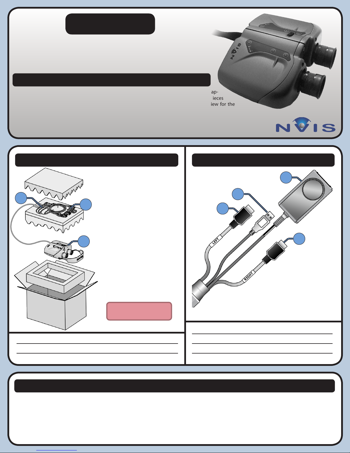
Package Contents Connections
1
1
1
Accessories
2
Coiled Binocular Cables
3
Ranger 47/35
Included in the Box
2
• Ranger 47/35
• Neck Strap
• Universal Power Supply
• Power Cable
3
• DVI to HDMI Adapters
• Cleaning Kit
• Setup Guide
Place Binoculars in anti-static
bag before wrapping cables.
3
1
Power Supply
2
USB Cable
3
HDMI Cable Left
4
HDMI Cable Right
2
4
Care & Maintenance
Protect the cables.
Do not pull or bend the power cable or signal cable. Do not place any heavy
objects on these cables. To disconnect the power cable or signal cable, always
pull from the plug, not the cable.
Use original NVIS packaging when shipping products.
NVIS products use precision-engineered optical and mechanical components
that can be damaged if not adequately protected during shipment.
Use only pure isopropyl alcohol and professional lens cleaning paper.
A sample cleaning kit is provided with your unit.
Use screen savers.
The Ranger OLED microdisplays are subject to image retention. Screen savers
must be used to prevent static images from lasting longer than 2 minutes.
Image retention is not covered by the NVIS Product Warranty.
PIN 104698 Rev B, CR-1076
Page 2
Step-by-Step
1
Tracker Mount
4
6
2
2
3
5
1
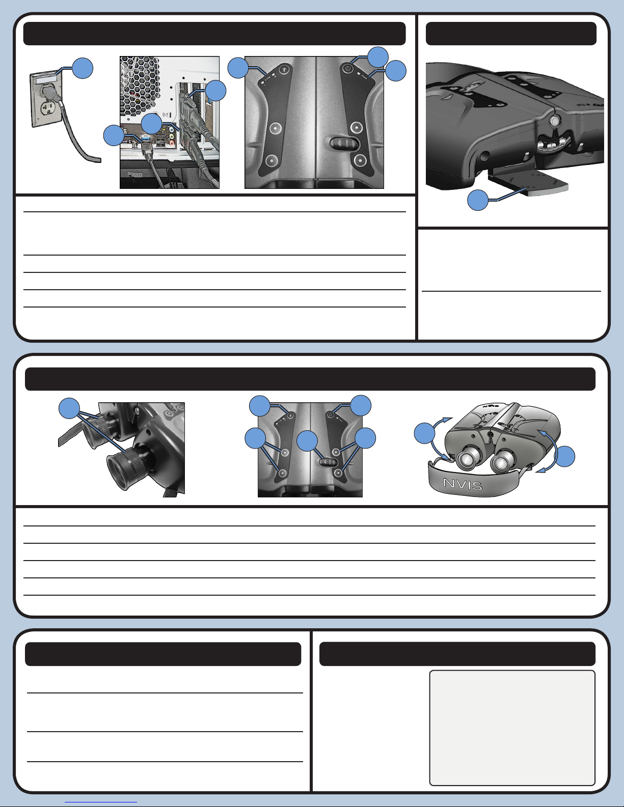
Plug the Ranger universal power supply into a standard 110-240 VAC outlet.
2
Connect one or both HDMI adapters to a PC graphics card, using the DVI to HDMI
adapters if needed. A single connection clones the image to both eyes. Use both connectors for stereoscopic applications.
3
Connect the USB cable to the PC.
4
Press and hold the POWER button for 2 seconds.
5
Power LED illuminates to indicate power is on.
6
L and R video LEDs illuminate when correct video format is supplied to left and right
channels, respectively.
Adjustments
1
2
3
5
1
1
Existing hole spacing accommodates
the InertiaCube orientation sensors.
Other trackers can be mounted via
custom plate or adhesive.
Consult manufacturer documentation for
optimal motion tracking hardware setup
and conguration.
4
3
6
6
1
Focus Adjustment Turn eyepieces to adjust focus
2
Brightness Button Cycles through 3 dierent levels of brightness
3
USB Buttons Programmable interaction using USB interface
4
Power Button Powers on/o device
5
Scroll Wheel Programmable interaction using USB interface
6
Interpupillary Distance Adjustment Pivot two halves of device around central hinge (axis) to adjust distance between oculars
Operating Notes
Power to Ranger must be turned on only after computer (IG) is completely
booted up.
Ranger is equipped with an accelerometer to turn o the displays when the
device is stationary for 2 minutes. Timeout duration and sensitivity may be
adjusted in NVIS Uni Software.
Full product specication, software, and documentation is available at
www.nvisinc.com.
Ranger is intended for use in standard oce environments and is not
designed for outdoor or harsh environmental conditions.
Customer Support
Online
www.nvisinc.com
E-mail
Phone
+1
571-201-8095
PIN 104698 Rev B, CR-1076
RMA Instructions
All product returns must include a Case
number. Customers can request a Case
number online, via e-mail, or by calling
NVIS and selecting the technical support
menu option. Please keep original
package materials for return shipments
to NVIS. Follow the diagram in the
Packing Contents section of this guide.
Please do not include any accessories.
 Loading...