

Page 1
Add Quick Guide cover
P/N:191-07DZ5-003MU
790i Quick Guide-Final.indd 1 1/4/2008 11:57:40
Page 2
2 ZOTAC nForce 780i-Supreme SLI Motherboard
ZOTAC nForce 790i-Supreme SLI
Motherboard
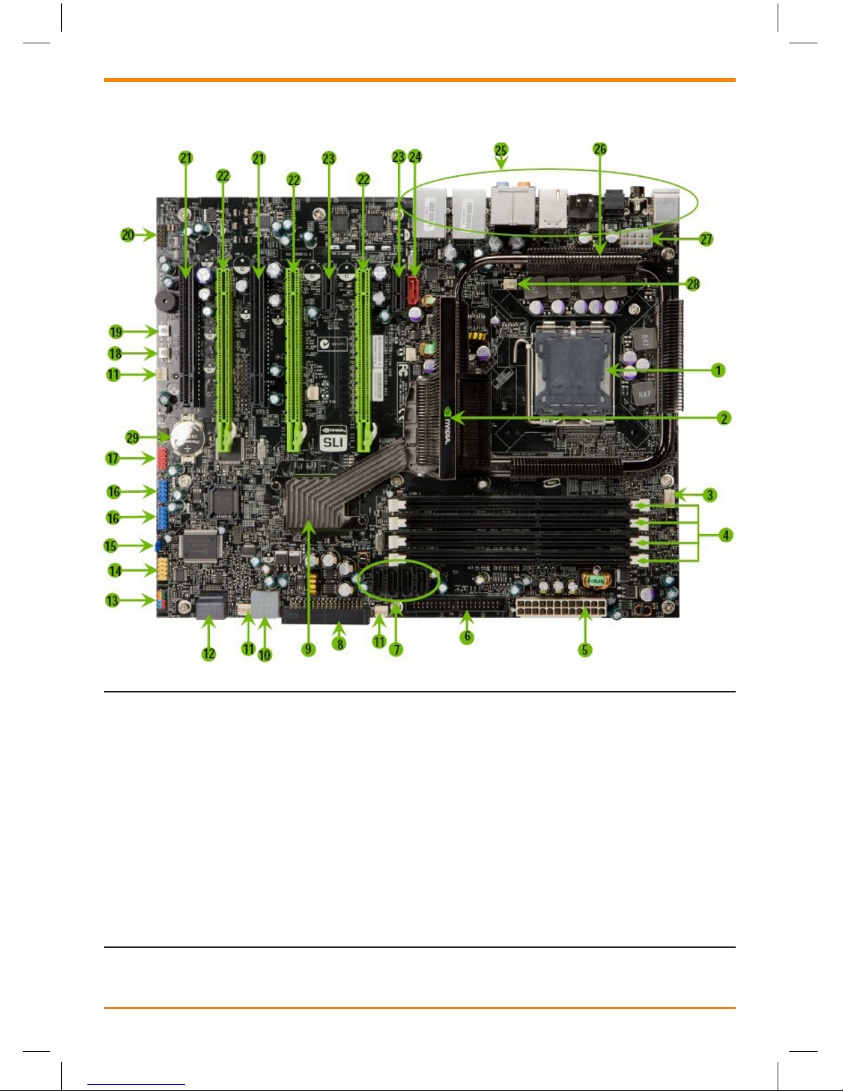
1. CPU Socket 11. Fan connectors 21. PCI slots
2. NVIDIA 790i Ultra SLI heatpipe 12. Serial-ATA (SATA) connectors 22. PCI Express x16 slots (SLI)
3. CPU fan connector 13. Front panel connector 23. PCI Express x1 slots
4. DDR3 DIMM Slots 0 - 3 14. Serial connector 24. SATA connectors
5. 24-pin ATX Power Connector 15. Jumper 25. Backpanel connectors
6. IDE Connector 16. USB headers 26. Heat dissipater
7. Serial-ATA (SATA) connectors 17. 1394a connector 27. 8-pin ATX_12V
power connector
8. FDD connector 18. Power button 28. MCP/SPP fan connector
9. NVIDIA MCP (passive heat sink) 19. Reset Button 29. Motherboard battery
790i Quick Guide-Final.indd 2 1/4/2008 11:57:40
Page 3

Quick Reference Guide 3
1. PS/2 Mouse Port
2. PS/2 Keyboard Port
3. Coaxial SPDIF
4. SPDIF output
5. eSATA
6. USB 2.0 ports (SIX)
7. 1394 (Firewire) Port
Port 2-Channel 4-Channel 6-Channel/8-Channel
Blue Line-In Line-In Line-In
Green Line-Out Front Speaker Out Front Speaker Out
Pink Mic In Mic In Mic In
Orange -- -- Center/Subwoofer
Black -- Rear Speaker Out Rear Speaker Out
Grey -- -- Side Speaker Out
8. Lan Port with LEDs to indicate status.
· Yellow/Light Up/Blink = 10 Mbps/Link/Activity
· Yellow and Green/Light Up/Blink = 100 Mbps/link/Activity
· Green/Light Up/Blink = 1000 Mbps/Link/Activity
Backpanel Connectors
PCI-E Slots
PCI-E 1 PCI-E 2 PCI-E 3
Single Graphics Card yes -- --
SLI yes yes --
3-Way SLI yes yes yes
NVIDIA SLI (Scalable Link Interface) is
a revolutionary technology that allows
two NVIDIA SLI graphics cards to work
together to deliver incredible 3D graphics
performance.
Your new motherboard can support up to
three PCI Express graphics cards linked
using SL.
PCI-E 1
PCI-E 2
PCI-E 3
790i Quick Guide-Final.indd 3 1/4/2008 11:57:41
Page 4
4 ZOTAC nForce 780i-Supreme SLI Motherboard
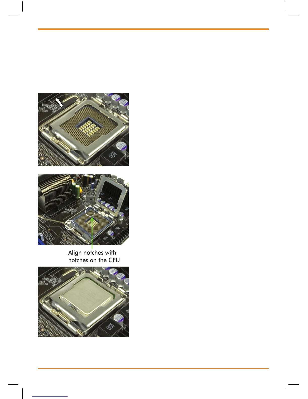
Installing the CPU
Be very careful when handling the CPU. Make sure not to bend or break any pins on
the back. Hold the processor only by the edges and do not touch the bottom of the
processor.
Use the following procedure to install the CPU onto the motherboard.
1. Unhook the socket lever by pushing down
and away from the socket.
2. Lift the load plate. There is a protective
socket cover on the load plate to protect the
socket when there is no CPU installed.
3. Remove the protective socket cover from the
load plate.
4. Remove the processor from its protective
cover, making sure you hold it only by the
edges. It is a good idea to save the cover so
that whenever you remove the CPU, you
have a safe place to store it.
5. Align the notches in the processor with the
notches on the socket.
6. Lower the processor straight down into the
socket with out tilting or sliding it into the
socket.
Note: Make sure the CPU is fully seated and
level in the sock
7. Close the load plate over the CPU and press
down while you close and engage the socket
lever.
Installing the CPU Fan
There are many different fan types that can be
used with this motherboard. Follow the
instruction that came with you fan assembly. Be
sure that the fan orientation is correct for your
chassis type and your fan assembly.
790i Quick Guide-Final.indd 4 1/4/2008 11:57:41
Page 5
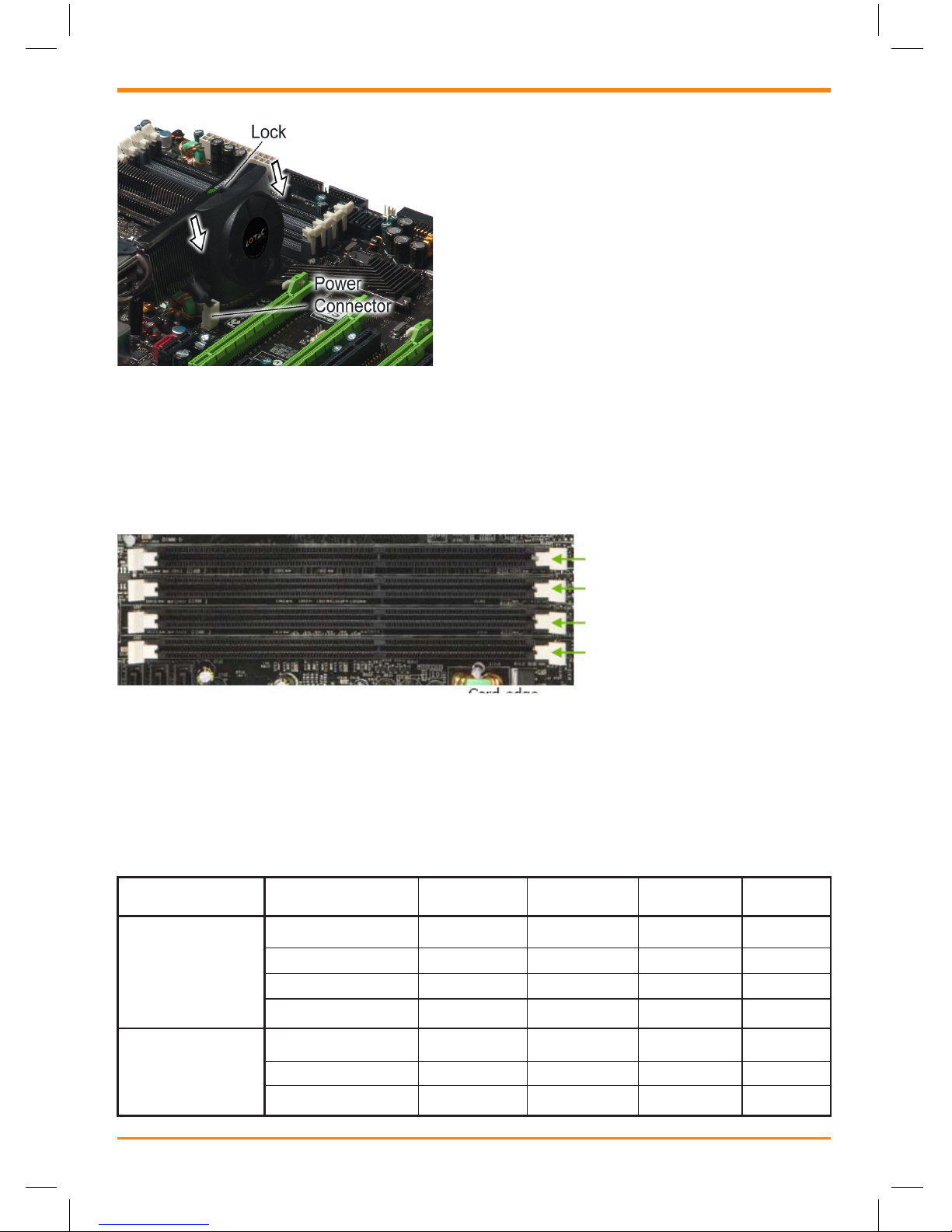
Installing Memory
Use the following procedure to install memory DIMMs into the slots on the
motherboard. Note that there is only one gap near the center of the DIMM slot. This
slot matches the slot on the memory DIMM to ensure the component is installed
properly.
1. Unlock a DIMM slot by pressing the module clips outward.
2. Align the memory module to the DIMM slot, and insert the module vertically into
the DIMM slot. The plastic clips at both sides of the DIMM slot automatically lock
the DIMM into the connector.
Quick Reference Guide 5
Memory Conguration
Installing Chipset Fan
The motherboard come with an chipset fan.
Follow the step to install the chipset fan.
1) Place the fan on the angled side of the
chipset fan.
2) Match the pins on the to the slits on the
heatsink
3) Slide the fan down until the fan is clipped
on the heatsink
DIMM Slot 0
DIMM Slot 2
DIMM Slot 1
DIMM Slot 3
Conguration DIMM0 DIMM1 DIMM2 DIMM3
Single Channel 1 Populated -- -- - 2 -- Populated -- - 3 -- -- Populated - 4 -- -- -- Populated
Dual Channel 5 Populated Populated -- - 6 -- -- Populated Populated
7 Populated Populated Populated Populated
790i Quick Guide-Final.indd 5 1/4/2008 11:57:42
Page 6
6 ZOTAC nForce 790i-Supreme SLI Motherboard
Power Connection
PWR1 is the main power supply connector located
along the edge of the board next to the DIMM
slots. Make sure that the power supply cable and
pins are properly aligned with the connector on the
motherboard. Firmly plug the power supply cable
into the connector and make sure it is secure.
PWR2, the 8-pin ATX 12V power connection, is
used to provide power to the CPU. Align the pins to
the connector and press rmly until seated.
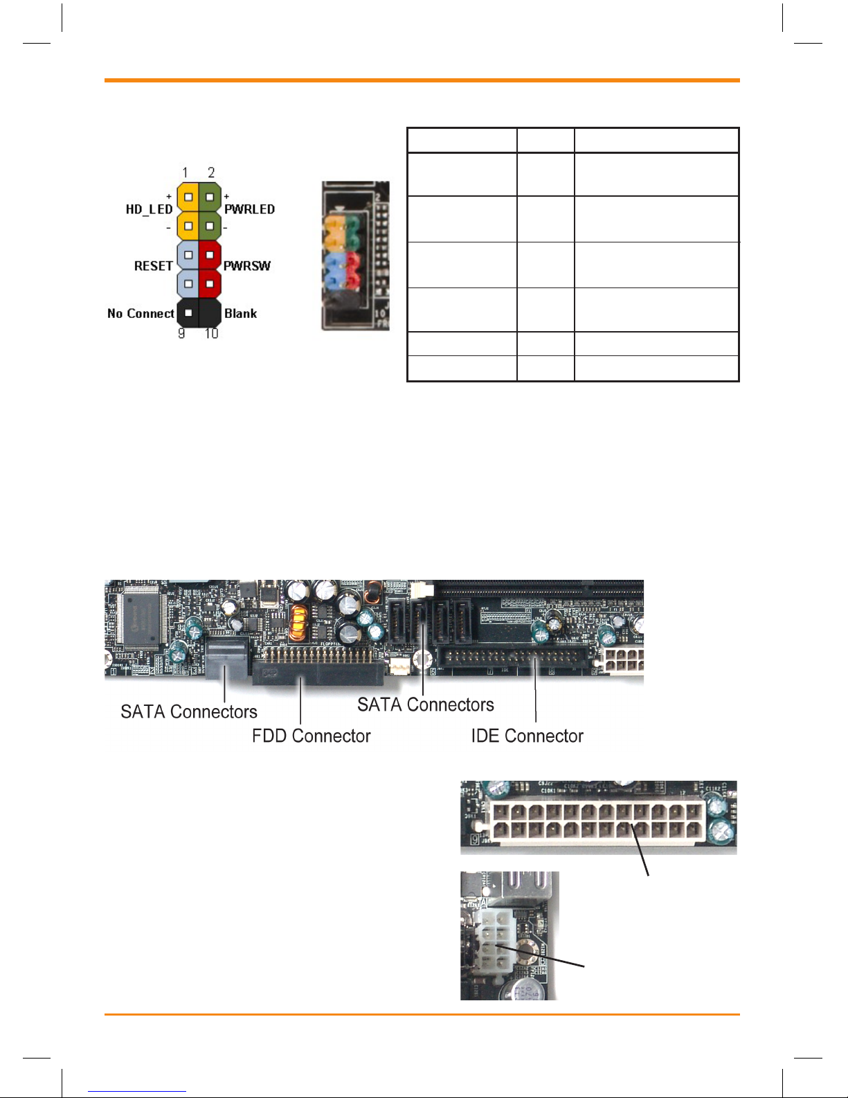
Connecting Front Panel Headers
Pin Description
HD_LED 1
3
PWRLED 2
4
RESET 5
7
PWRSW 6
8
No Connect 9 No Connect
Empty 10 Empty
Hard disk active LED
Front panel LED
Reset switch
Power switch
Connecting to Storage Device
The IDE connector supports Ultra ATA 133/100/66 IDE hard disk drives.
The Serial ATA connector is used to connect the Serial ATA device to the
motherboard.
The FDD connector supports a standard 360K, 720K, 1.2M, 1.44m, and a 2.88M
oppy disk drive (FDD).
24-pin ATX Power
(PWR1)
8-pin ATX
12V Power
(PWR2)
191-07DZ5-003MU
790i Quick Guide-Final.indd 6 1/4/2008 11:57:42
 Loading...