

Page 1

DA_09452-003 | July 8, 2019
User Guide
JETSON TX2 DEVELOPER
KIT
Page 2
Version
Date
Authors
Description of Change
DOCUMENT CHANGE HISTORY
DA_09452-003
2.0 March 28, 2019 jsachs, plawrence Revision for L4T r32.1.
3.0 July 8, 2019 jsachs, plawrence
Revision for SDK Manager and L4T
r32.2.
NOTE
Welcome to the NVIDIA Jetson platform! There two key things you should do right
away:
1. Sign up for the NVIDIA Developer Program
questions and contribute on the NVIDIA Jetson Forums, gives access to all
documentation and collateral on the Jetson Download Center, and more.
2. Read this User Guide! After that, check out these important links:
– this enables you to ask
• Jetson FAQ
– Please read the FAQ.
• Support Resources – This web page links to important resources, including the
Jetson Forum and the Jetson Ecosystem page.
• L4T Release Notes – L4T is a key component of the Jetson platform, and
provides the sample filesystem for your developer kit. Please read the latest
release notes.
• Thanks,
The NVIDIA Jetson team
Jetson TX2 Developer Kit DA_09452-003 | ii
Page 3

TABLE OF CONTENTS
Note .........................................................................................ii
Jetson TX2 Developer Kit ............................................................... 4
Included in the box ............................................................................. 4
Developer Kit Interfaces ....................................................................... 5
Note about carrier board revisions ........................................................ 6
Interface Details ............................................................................. 6
JetPack ................................................................................... 10
Summary of JetPack Components ........................................................... 10
How to Install JetPack ........................................................................ 12
Download SDK Manager on the Linux Host Computer .................................. 12
Connect Developer Kit to the Linux Host Computer ................................... 12
Put Developer Kit into Force Recovery Mode ........................................... 13
Run SDK Manager ............................................................................ 13
Working with L4T ....................................................................... 14
Compliance ............................................................................... 15
United States ................................................................................ 15
Canada ........................................................................................ 16
European Union .............................................................................. 17
Australia and New Zealand ................................................................ 18
Japan ......................................................................................... 19
South Korea .................................................................................. 19
Taiwan ........................................................................................ 20
China .......................................................................................... 21
Singapore ..................................................................................... 21
Environmental Disclosures ................................................................. 21
China/Taiwan RoHS Material Content Declaration ..................................... 22
Jetson TX2 Developer Kit DA_09452-003 | iii
Page 4

JETSON TX2 DEVELOPER KIT
The NVIDIA® Jetson™ TX2 Developer Kit gives you a fast, easy way to develop software
and hardware for the Jetson TX2 AI supercomputer on a module. Jetson TX2 is ideal for
applications requiring high computational performance in a low power envelope.
NVIDIA JetPack™ SDK supports both your developer kit and host development
platform. It includes:
• Sample Linux filesystem with NVIDIA drivers
• AI and Computer Vision libraries and APIs
• Developer tools
• Documentation and sample code
Before using your developer kit, you must install JetPack. A Linux host computer is
required; for details, see How to Install JetPack
Minimum system requirements for the host computer are:
• Ubuntu Linux x64 v16.04 or v18.04
• A valid Internet connection
• At least 23GB of disk space
, below.
INCLUDED IN THE BOX
The Jetson TX2 Developer Kit includes:
• Jetson TX2 module (P3310) with thermal solution
• Reference carrier board (P2597)
• Power supply with AC cord
• USB Micro-B to USB A cable
• USB Micro-B to Female USB A cable
• (2x) WLAN/Bluetooth antenna
Jetson TX2 Developer Kit DA_09452-003 | 4
Page 5
DEVELOPER KIT INTERFACES
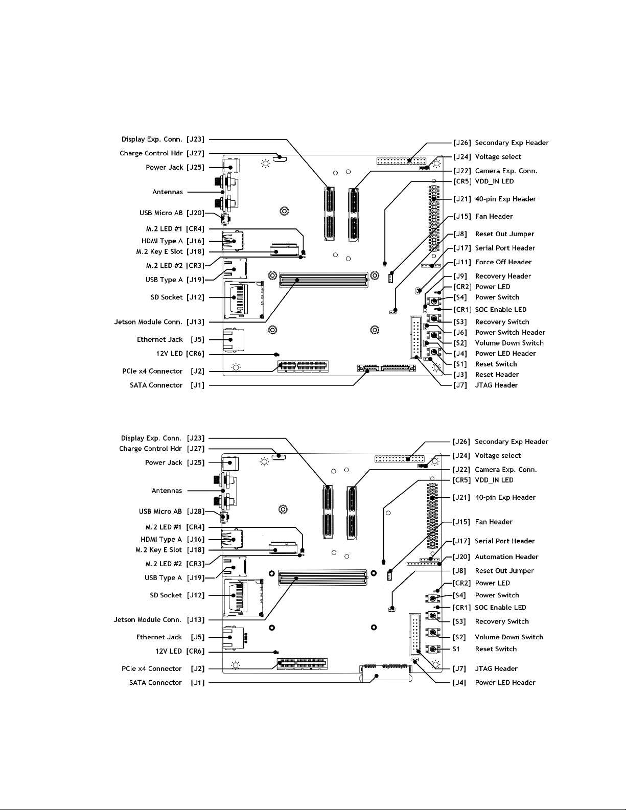
Top view of developer kit carrier board (revisions B02 and B0 4 )
Top view of developer kit carrier board (revision C02)
Jetson TX2 Developer Kit DA_09452-003 | 5
Page 6

Note about carrier board revisions
The B02 and B04 revision carrier boards are extremely similar. B04 added the CR5 and
CR6 LEDs and some minor circuit changes. The C02 revision included changes in
support of Jetson TX2i and Jetson TX2 4GB modules, consolidation of button header pins
into a single pin header, and changing the SATA connector to a right angle type to avoid
possible conflict with a PCIe card.
See the Jetson TX2 Developer Kit Carrier Board Specification
for comprehensive information.
Interface Details
This list highlights some of the Jetson TX2 Developer Kit carrier board interfaces.
• [CR1] Green LED indicates when SoC is enabled.
• [CR2] Green LED indicates when carrier board is powered.
• [CR3] Green LED indicates when [J18] M.2 Key E connector pin 6 is active.
• [CR4] Green LED indicates when [J18] M.2 Key E connector pin 16 is active.
• [CR5] Red LED indicates when main power supply is connected and active.
• [CR6] Red LED Indicates when the 12V supply for PCIe/SATA is active.
• [J1] SATA connector includes both data and power.
• [J2] PCIe x4 connector routes to a x4 PCIe 2.0 controller.
• [J4] The Power LED header can connect to a remote power LED.
• [J5] 10/100/1000 BASE-T Ethernet.
• [J12] Full-size SD Card interface supports up to SDR104 card mode (UHS-1).
• [J13] 400-pin (8 x 50) connector for the Jetson module. The Jetson TX2 Developer
Kit carrier board supports these Jetson modules: Jetson TX2, Jetson TX2i, Jetson
TX2 4GB, and Jetson TX1. See the L4T Development Guide
software support for those modules.
• [J15] 4-pin fan header for 5V PWM fan. The Jetson TX2 module included with
the developer kit already has thermal solution attached including Delta
Electronics AFB0405MA-AFGE
• [J16] HDMI 2.0.
• [J18] M.2 Key E connector can be used for wireless networking cards, and
includes interfaces for PCIe (x1), USB 2.0, UART, I2S & I2C.
• [J19] USB 3.0 Type A.
• [J20 B02/B04 or J28 C02] USB 2.0 Micro-AB connector.
)
for details about
This connector can be used to flash the developer kit, and provides access to USB
Device Mode features when the developer kit is running.
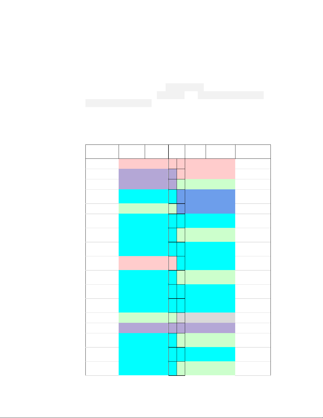
• [J21] 40-pin expansion header includes:
o Power pins.
Jetson TX2 Developer Kit DA_09452-003 | 6
Page 7
Signal
voltage
Signal
voltage
3
4
Audio I2S
MCLK
3.3V
or 1.8V
9
10
3.3V
or 1.8V
Audio I2S
CLK
3.3V
or 1.8V
3.3V
or 1.8V
Digital Mic
Input
3.3V
or 1.8V
3.3V
or 1.8V
3.3V
or 1.8V
3.3V
or 1.8V
3.3V
or 1.8V
27
28
3.3V
or 1.8V
3.3V
or 1.8V
Digital Mic
Clock
3.3V
or 1.8V
Two 3.3V power pins and two 5V power pins. These are not switchable;
power is always available when the developer kit is connected to power.
o Interface signal pins.
By default, all interface signal pins are 3.3V, but some can be configured for
1.8V. See [J24] information below.
L4T provides a Python library, Jetson.GPIO, for controlling GPIOs. The
library has the same API as RPi.GPIO. See /opt/nvidia/jetsongpio/doc/README.txt on your Jetson system for details.
By default, all interface signal pins are configured as GPIOs, except pins 3
and 5 and pins 27 and 28, which are I2C SDA and SCL, and pins 8 and 10,
which are UART TX and RX.
Optional Default
3.3V Supply 1 2 5.0V Supply
I2C1 SDA 3.3V
I2C1 SCL 3.3V 5 6 Ground
GPIO
Ground
UART RTS GPIO 3.3V 11 12
GPIO
GPIO 3.3V 15 16
3.3V Supply 17 18
SPI1 MOSI GPIO
SPI1 MISO GPIO
Pin
7 8 3.3V UART TXD GPIO
13 14
19 20
21 22 3.3V GPIO
Default Optional
5.0V Supply
3.3V UART RXD GPIO
GPIO
Ground
GPIO
GPIO
Ground
SPI1 SCLK GPIO
Ground 25 26
I2C0 SDA 3.3V
GPIO
GPIO 3.3V 31 32
GPIO
Jetson TX2 Developer Kit DA_09452-003 | 7
23 24
29 30
33 34
GPIO SPI1 CS0
Not Used
3.3V I2C0 SCL
Ground
GPIO
Ground
Page 8
Signal
voltage
Signal
voltage
Audio I2S
LRCK
3.3V
or 1.8V
3.3V
or 1.8V
Audio I2S
DIN
3.3V
or 1.8V
Audio I2S
DOUT
Signal
voltage
Signal
voltage
GPIO
3.3V
1 2 3.3V Supply
1.8V
Supply
CAN0 RX
3.3V
5 6 -
GPIO
CAN0 TX
3.3V
7 8 5.0V Supply
GPIO
3.3V
9
10 Ground
I2C2
CLK
I2C2
SDA
WDT
OUT
I2C3
CLK
I2C3
DAT
Optional Default
GPIO
GPIO 3.3V 37 38
Ground 39 40
Pin
35 36 3.3V GPIO UART CTS
Default Optional
GPIO
GPIO
• [J22] The camera connector supports up to six directly connected cameras via
CSI-2, or up to 12 cameras via the virtual channel feature of CSI-2. The connector
also includes some interface options for audio (I2S & DMIC).
• [J24] The voltage select header enables either 3.3V or 1.8V for these [J21] 40-pin
expansion header pins:
Pins 7, 12, 13, 16, 18, 19, 21, 23, 24, 29, 32, 33, 35, 38, and 40
The 3.3V level is selected when a jumper is on [J24] pins 1-2. The 1.8V level is
selected when a jumper is on [J24] pins 2-3.
• [J25] Use the included developer kit power supply with this DC power jack.
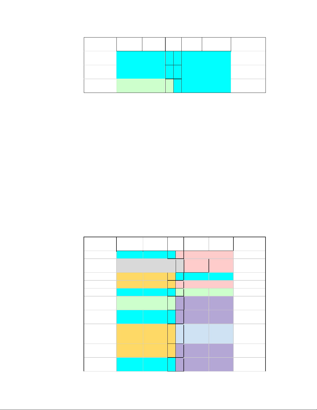
• [J26] 30-pin expansion header includes:
o Power pins.
One 1.8V power pin, one 3.3V power pin, and one 5V power pin. These are
not switchable; power is always available when the developer kit is
connected to power.
o Interface signal pins.
Optional Default
Not Used 3 4
Ground 11 12 1.8V
GPIO 3.3V 13 14 1.8V
CAN1 RX 3.3V 15 16
CAN1 TX 3.3V 17 18 1.8V
GPIO 3.3V 19 20 1.8V
Pin
Default Optional
GPIO
GPIO
RESET
GPIO
Jetson TX2 Developer Kit DA_09452-003 | 8
Page 9

Signal
voltage
Signal
voltage
Ground
21
22
1.8V
GPIO
I2S1
SDOUT
I2S1
SDIN
I2S1
LRCLK
SPDIF OUT
or GPIO
DSPK
OUT CLK
SPDIF IN
or GPIO
DSPK
OUT DAT
Optional Default
I2S1 CLK 1.8V 23 24 1.8V
1.8V 25 26 1.8V
1.8V 27 28
1.8V 29 30
Pin
Default Optional
Ground
Not Used
Jetson TX2 Developer Kit DA_09452-003 | 9
Page 10

JETPACK
NVIDIA JetPack SDK is the most comprehensive solution for building AI applications. It
includes the latest OS images for Jetson products, along with libraries and APIs,
samples, developer tools, and documentation.
SUMMARY OF JETPACK COMPONENTS
This section briefly describes each component of JetPack. For additional details about
these components, see the online documentation for JetPack at:
https://docs.nvidia.com/jetson/jetpack/index.html
OS Image
JetPack includes a sample file system derived from Ubuntu.
Libraries and APIs
JetPack libraries and APIs include:
• TensorRT and cuDNN for high-performance deep learning applications
• CUDA for GPU accelerated applications across multiple domains
• NVIDIA Container Runtime for containerized GPU accelerated applications
• Multimedia API package for camera applications and sensor driver development
• VisionWorks and OpenCV for visual computing applications
Sample Applications
JetPack includes several samples which demonstrate the use of JetPack components. The
examples are stored in the reference filesystem and can be compiled on the developer
kit.
Jetson TX2 Developer Kit DA_09452-003 | 10
Page 11

JetPack component
Sample locations on reference filesystem
• JetPack Documentation
•
•
•
•
•
• NVIDIA Container Runtime
• VisionWorks Documentation
•
•
•
•
•
• Visual Profiler
TensorRT /usr/src/tensorrt/samples/
cuDNN /usr/src/cudnn_samples_<version>/
CUDA /usr/local/cuda-<version>/samples/
Multimedia API /usr/src/tegra_multimedia_api/
/usr/share/visionworks/sources/samples/
VisionWorks
OpenCV /usr/share/OpenCV/samples/
/usr/share/visionworks-tracking/sources/samples/
/usr/share/visionworks-sfm/sources/samples/
Developer Tools
JetPack includes the following developer tools. Some are used directly on a Jetson
system, and others run on a Linux host computer connected to a Jetson system.
• Tools for application development and debugging:
• Nsight Eclipse Edition
on the Linux host computer. Supports all Jetson products.
for development of GPU accelerated applications: Runs
• CUDA-GDB for application debugging: Runs on the Jetson system or the Linux
host computer. Supports all Jetson products.
• CUDA-MEMCHECK for debugging application memory errors: Runs on the
Jetson system. Supports all Jetson products.
• Tools for application profiling and optimization:
• Nsight Systems
Linux host computer. Supports all Jetson products.
• nvprof for application profiling across GPU and CPU: Runs on the Jetson system.
Supports all Jetson products.
• Visual Profiler for application profiling across GPU and CPU: Runs on the Linux
host computer. Supports all Jetson products.
• Nsight Graphics for graphics application debugging and profiling: Runs on the
Linux host computer. Supports all Jetson products.
Documentation
Documents that are relevant to developers using JetPack include:
L4T Development Guide
L4T Release Notes
TensorRT Documentation
cuDNN Documentation
CUDA Toolkit
Jetson TX2 Developer Kit DA_09452-003 | 11
for application profiling across GPU and CPU: Runs on the
Nsight Eclipse Edition Documentation
CUDA-GDB Documentation
CUDA-MEMCHECK Documentation
Nsight Systems
nvprof
Page 12

• Multimedia API Reference
• OpenCV Documentation
• Nsight Graphics
HOW TO INSTALL JETPACK
Installing JetPack to your developer kit requires you to perform these steps, detailed in
the sections below:
1. Download and install NVIDIA SDK Manager on the Linux host computer.
2. Connect your developer kit to the Linux host computer.
3. Put your developer kit into Force Recovery Mode.
4. Use SDK Manager to select and install desired components.
Download SDK Manager on the Linux Host Computer
You must have a Linux host computer to run SDK Manager and flash the developer kit.
Supported host operating systems are:
• Ubuntu Linux x64 Version 18.04 or 16.04
Follow these instructions to download and install NVIDIA SDK Manager
Note: SDK Manager can flash and install software on a target Jetson device, but it
cannot run directly on that device. Whether or not a Jetson device is
present, you can use SDK Manage r to update software on the Linux host.
.
Connect Developer Kit to th e Linux Host Computer
Prepare your Jetson TX2 Developer Kit for initial setup as follows. For “headless” setup,
skip the first two steps.
• Connect an external HDMI display to the carrier board’s HDMI port.
• Connect a USB keyboard and mouse to a USB hub (not included) and connect the
hub to the developer kit’s USB Type-A port. (The USB Micro AB port will be
needed for flashing.)
• Insert the Micro-B end of the included USB Micro-B to USB A cable to the carrier
board’s USB Micro-AB port. Connect the other end to your Linux host computer.
• Connect the included AC adapter to the carrier board's power jack. Plug the AC
adapter into an appropriately rated electrical outlet.
Jetson TX2 Developer Kit DA_09452-003 | 12
Use only the supplied AC adapter, as it is appropriately rated for your device.
Page 13

Put Developer Kit into Force Recovery Mode
The developer kit must be in Force Recovery mode (RCM) to enable the installer to
transfer system software to the Jetson module.
1. Connect the developer kit as described above. It must be powered off.
2. Press and hold down the Force Recovery button.
3. Press and hold down the Power button.
4. Release the Power button, then release the Force Recovery button.
Run SDK Manager
NVIDIA SDK Manager enables installation of software to the Jetson module and/or your
Linux host computer.
For full instructions, see the SDK Manager documentation
Note:
After the Jetson is flashed with the OS, it reboots and prompts you for initial
configuration information like keyboard layout, username and password, etc.
If no display is attached to the developer kit during this first boot, the initial
configuration will be “headless.” That is, you must communicate with the
developer kit through a serial application on the Linux host computer (e.g.,
puTTY) connected via a host serial port to the correct local serial device.
.
Jetson TX2 Developer Kit DA_09452-003 | 13
Page 14

WORKING WITH L4T
NVIDIA L4T (the operating system component of JetPack) provides the Linux kernel,
Bootloader, board support package (BSP), and sample filesystem for Jetson developer
kits. SDK Manager can install L4T along with all the other JetPack components to get
your developer kit up and running quickly.
L4T is also available for download directly from the main L4T page
Developer Site. See the “Quick Start Guide” section of the L4T Development Guide for
flashing instructions.
See also the Platform Adaptation and Bring-Up Guide, which describes how to port the L4T
BSP and Bootloader from your developer kit to a new hardware platform incorporating
the Jetson module. Porting L4T to a new device enables use of the other JetPack
components on that device, along with the software you’ve created using the developer
kit.
on the Jetson
Jetson TX2 Developer Kit DA_09452-003 | 14
Page 15

COMPLIANCE
The NVIDIA Jetson TX2 Developer Kit is compliant with the regulations listed in this
section. Compliance marks, including the FCC and IC ID numbers, can be found at:
https://developer.nvidia.com/embedded/support
United States
Federal Communications Commiss ion ( FCC)
FCC ID: VOB-P3310
This device complies with part 15 of the FCC Rules. Operation is subject to the following
two conditions: (1) this device may not cause harmful interference, and (2) this device
must accept any interference received, including any interference that may cause
undesired operation of the device.
This equipment has been tested and found to comply with the limits for a Class B digital
device, pursuant to Part 15 of the FCC Rules. These limits are designed to provide
reasonable protection against harmful interference in a residential installation. This
equipment generates, uses and can radiate radio frequency energy and, if not installed
and used in accordance with the instructions, may cause harmful interference to radio
communications. However, there is no guarantee that interference will not occur in a
particular installation.
Jetson TX2 Developer Kit DA_09452-003 | 15
Page 16

Compliance
If this equipment does cause harmful interference to radio or television reception, which
can be determined by turning the equipment off and on, the user is encouraged to try to
correct the interference by one or more of the following measures:
• Reorient or relocate the receiving antenna.
• Increase the separation between the equipment and receiver.
• Connect the equipment into an outlet on a circuit different from that to which the
receiver is connected.
• Consult the dealer or an experienced radio/TV technician for help.
FCC Warning: The FCC requires that you be notified that any changes or modifications
to this device not expressly approved by the manufacturer could void the user’s
authority to operate the equipment.
RF Radiation Exposure Statement
This equipment complies with FCC RF radiation exposure limits set forth for an
uncontrolled environment. This equipment should be installed and operated with a
minimum distance of 20 centimeters between the radiator and your body.
Only those antennas with same type and lesser/equal gain filed under this FCC ID
number can be used with this device.
Underwriters Laboratories (UL)
UL Listed Product Logo for Jetson TX2 Developer Kit, model name P2597.
I.T.E E204896
UL Recognized Component Logo for Embedded System Module, model name P3310.
Canada
Industry Canada (IC)
Jetson TX2 Developer Kit DA_09452-003 | 16
Page 17

Compliance
IC: 7361A-P3310
CAN ICES-3(B)/NMB-3(B)
This device complies with Industry Canada’s licence-exempt RSSs of the Industry Canada
Rules. Operation is subject to the following two conditions: (1) this device may not cause
interference, and (2) this device must accept any interference, including interference that
may cause undesired operation of the device.
5150–5250 MHz is only for indoor use to reduce the potential for harmful interference to
co-channel mobile satellite systems;
Ce dispositif est conforme à la norme RSS-247 d'Industrie Canada applicable aux
appareils radio exempts de licence. Son fonctionnement est sujet aux deux conditions
suivantes: (1) le dispositif ne doit pas produire de brouillage préjudiciable, et (2) ce
dispositif doit accepter tout brouillage reçu, y compris un brouillage susceptible de
provoquer un fonctionnement indésirable.
RF Radiation Exposure Statement:
Jetson Dev Kit has been tested and complies with IC RSS 102 RF radiation exposure
limits set forth for an uncontrolled environment when used with the NVIDIA
accessories supplied or designated for this product. To satisfy IC exposure requirements,
a separation distance of at least 20 cm must be maintained between the antenna of this
device and persons during device operation. The use of any other accessories may not
ensure compliance with IC RSS 102RF exposure guidelines.
Déclaration d'exposition aux radiations:
La Jetson Dev Kit a ete testee conformemment aux normes d’exposition d’emission RF
de la IC RSS 102 pour un environement non controle lors d’utilisation avec les
accessoires fournis or recommendes par NVIDIA. Pour satisfaire aux exigences
d'exposition IC, une distance de séparation d'au moins 20 cm doit être maintenue entre
l'antenne de cet appareil et des personnes pendant le fonctionnement de l'appareil.
L’utilisation d’accessoires autres que ceux recommendes par NVIDIA ne guarantis pas
la compatibilite avec les normes d’emission RF de la IC RSS 102.
European Union
European Conformity; Conformité Europée nne ( C E)
Jetson TX2 Developer Kit DA_09452-003 | 17
Page 18

Compliance
This device bears the CE mark in accordance with Directive 2014/53/EU.
This device complies with the following directives:
• Radio Equipment Directive 2014/53/EU
• RoHS Directive 2011.65.EU
The full text of the EU declaration of conformity is available at:
https://developer.nvidia.com/embedded/support
A copy may also be obtained directly from NVIDIA GmbH (Floessergasse 2, 81369
Munich, Germany).
This device operates in the following frequency bands and maximum transmitted
power:
Frequency Band EIRP (dBm) EIRP (mW)
2402 - 2480 MHz (Bluetooth) 11.54 14
2412 - 2472 MHz 20 100
5180 - 5320 MHz 23 200
5500 - 5700 MHz 23 200
5745 - 5825 MHz 14 25
Warning
• Operation in 5150 - 5350 MHz frequency band is restricted to indoor use.
• This equipment must be installed and operated with a minimum distance of 20 cm
between the radiator and your body.
• Use antennas with the same Type and Gain for this device.
• Any modifications to this device, not expressly approved by the manufacturer, voids
the user authority to operate the equipment.
Hardware Version: 945-82771-0005-000
Firmware Version: 7.35.221.11 (WLAN); 030A0525 (Bluetooth)
Australia and New Zealand
Australian Communications and Media Authority (RCM)
Jetson TX2 Developer Kit DA_09452-003 | 18
Page 19

Compliance
This product meets the applicable EMC requirements for Class B, I.T.E equipment and
applicable radio equipment requirements.
Japan
Voluntary Control Council for Interference (VCCI)
Radio/ Telecommunications Certification
South Korea
Radio Research Agency (RRA)
Korean Agency for Technology and Standards (KATS)
MSIP-CRM-NVA-P3310
MSIP-RMM-NVA-P2597
B급 기기
(가정용 방송 통신기자재) 로 가정에서 사용하는 것을 목적으로 하며, 모
Jetson TX2 Developer Kit DA_09452-003 | 19
이 기기는 가정용(B급) 전자파적합기기로서 주
든 지역에서 사용할 수 있습니다.
Page 20

Taiwan
National Communications Commission
CCAJ17LP1260T1
注意!
依據 低功率電波輻射性電機管理辦法
第十二條
經型式認證合格之低功率射頻電機,非經許可,公司、商號或使用者均不得擅自變更頻率、加大功率
或變更原設計之特性及功能。
第十四條
Compliance
低功率射頻電機之使用不得影響飛航安全及干擾合法通信;經發現有干擾現象時,應立即停用,並改
善至無干擾時方得繼續使用。
前項合法通信,指依電信法規定作業之無線電通信。
低功率射頻電機須忍受合法通信或工業、科學及醫療用電波輻射性電機設備之干擾。
模組認證合格標簽 (ID):
“ CCAJ17LP1260T1"
如果使用本模組之平台, 無法在外部看見審驗合格標籤時,應在該
平台的外部明顯標示
“內含射頻模組 CCAJ17LP1260T1.
應避免影響附近雷達系統之操作。
高增益指向性天線只得應用於固定式點對點系統。
電磁波曝露量MPE標準值1mW/cm², 送測產品實測值為: .109 mW/cm².
Jetson TX2 Developer Kit DA_09452-003 | 20
Page 21

China
State Radio Regulations Committee
CMIIT ID: 2015AJ7078
本设备包含型号核准代码为CMIIT ID: XXXXYYZZZ 的无线电发射模块
Singapore
Info-Communications Development Authority of Singapore
Compliance
Environmental Disclosures
California Prop 65 Warning – California law requires this warning to be provided to
California customers.
Prop 65 Warning: This product contains chemicals known to the State of California to
cause cancer and birth defects or other reproductive harm.
Jetson TX2 Developer Kit DA_09452-003 | 21
Page 22

限用物質含有情况標示聲明書
設備名稱:
Equipment Name: Jetson TX2 Developer Kit
單元
限用物質及其化學符號
汞
六價
多溴聯苯
多溴二苯
China/Taiwan RoHS Ma t er ial Content Declaration
Declaration of the presence condition of the Restricted Sustances Marking
Jetson TX2 Developer Kit
Compliance
Parts
印刷電路部件
PCA
處理器
Processor
存儲設備
System memory
電源設備
Power adapter
攝像頭
Camera module
天線
Antenna
機械部件
Mechanicals
線材/連接器
Cables/Connectors
Restricted substances and its chemical symbols
铅
(Pb )
- O O O O O
O O O O O O
- O O O O O
- O O O O O
- O O O O O
- O O O O O
- O O O O O
- O O O O O
(Hg)
镉
(Cd)
铬
(Cr(VI))
(PBB)
醚
(PBDE)
焊接金屬
Soldering material
助焊劑,錫膏,標籤及
耗材
Flux, Solder Past e ,
label and other
consumable materials
備考1:O:系指該限用物質未超出百分比含量基準值
Note 1: O:indicates that the percentage content of the restricted substance does not exceed the
percentage of reference value of presence.
備考2: -:系指該项限用物質为排外项目。
Note 2:-:indicates that the restricted subst an c e cor r e sp onds to the exemp t io n .
此表中所有名稱中含 “-” 的部件均符合歐盟 RoHS 立法。
All parts named in this table with an “-” are in com p l ian c e with the European Union’s RoHS Legislation.
Jetson TX2 Developer Kit DA_09452-003 | 22
O O O O O O
O O O O O O
Page 23

Compliance
注:環保使用期限的參考標識取决與產品正常工作的温度和濕度等條件
Note: The referenced Environmental Protection U se P e riod Marking was determined according to normal
operating use cond itions of the product su c h as temperature and humidity.
Jetson TX2 Developer Kit DA_09452-003 | 23
Page 24

Notice
© 2017-2019 NVIDIA Corporation. All rights reserved. NVIDIA, the NVIDIA logo, Tegra, Jetson, and JetPack are
trademarks a nd/or regis tered trad emarks of N VIDIA Corpo ration in th e U.S. and oth er countri es. Other c ompany
and produc t names may be trad emarks of the r esp ective c ompa nies with whi ch th ey are as soci ated. ALL NVIDIA
DESIGN SPECIFICATIO NS, REF ER ENC E BO ARDS, FILES, DRAWINGS, D IAGNOST ICS, LISTS, AND OT HER DOCUMENTS
(TOGETHER AND SEPARATELY, "MATERIALS") ARE BEING PROVIDED "AS IS." NVIDIA MAKES NO WARRANTIES,
EXPRESS, IMPLIED, STATUTORY, OR OTHERWISE WITH RESPECT TO THE MATERIALS, AND ALL EXPRESS OR
IMPLIED CONDITIO NS, REPRES ENT ATIONS AND W ARR ANTIES , INCLU DING ANY I MPLIE D WARR ANTY OR C ONDIT ION
OF TITLE, MERCHANTABILITY, SATISFACTORY QUALITY, FITNESS FOR A PARTICULAR PURPOSE AND NONINFRINGEMENT, ARE HEREBY EXCLUDED TO THE MAXI MU M EXTENT PERMITTED BY L AW.
Information furnished is believed to be accurate and reliable. However, NVIDIA Corporation assumes no
responsibi lity fo r the c onseq uenc es of us e of such i nform ation or fo r any i nfrin gemen t of p atents or ot her ri ghts
of third parti es that ma y resu lt fro m its use . No lic ense is gr anted b y imp licatio n or oth erwis e under a ny pa tent
or patent rights of NVIDIA Corporation. Specifications mentioned in this publication are subject to change
without notice. This publication supersedes and replaces all information previously supplied. NVIDIA
Corporation products are not authorized for use as critical components in life support devices or systems
without express written approval of NVIDIA Corporation.
Trademarks
NVIDIA and the NVID IA lo go a re tra demar ks o r r egis ter ed trademarks of NVIDIA Corporation in the United States
and other countries. Other company and product names may be trademarks of the respective companies with
which they are associated.
www.nvidia.com
 Loading...