

Page 1
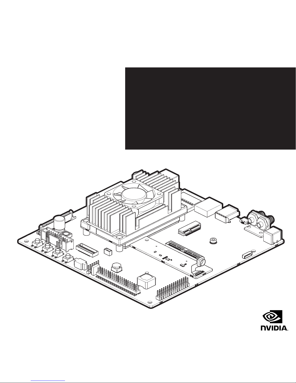
NVIDIA® JETSON TX1
DEVELOPER KIT
QUICK START GUIDE
Page 2

INTRODUCTION
The NVIDIA® Jetson TX1 Developer Kit is a full-featured
development platform for visual computing. It is ideal for
applications requiring high computational performance
in a low power envelope. The Jetson TX1 Developer kit is
designed to get you up and running quickly by shipping
pre-flashed with a Linux environment. It includes support
for many common APIs and is supported by the complete
NVIDIA development tool chain. The board exposes many
standard hardware interfaces, enabling a highly flexible
and extensible platform.
Go to http://developer.nvidia.com/embedded-computing
for access to software updates and the developer SDK
supporting the OS image and host development platform
that you want to use. The SDK includes an OS image that
you will load onto your device, developer tools, supporting
documentation, and code samples to help you get started.
GETTING STARTED
Individual development efforts will vary and may
result in modifications to the system configuration. It
is recommended that you begin with the basic system
configuration (as shipped) to ensure proper system
operation prior to any further development.
!
CAUTION: The NVIDIA® Jetson TX1 Developer
Kit contains ESD-sensitive parts. Always use
appropriate anti-static and grounding techniques
when working with the system. Failure to do so
can result in ESD discharge to sensitive pins, and
irreparably damage your Jetson TX1 Developer
Kit. NVIDIA will not replace units that have been
damaged due to ESD discharge. Always disconnect
any power source prior to adding additional
modules or connecting peripheral devices to the
developer board. It is important that all modules
are properly seated in their connectors to ensure
proper operation and to avoid damaging the module
or the carrier board.
Installing the antennas
Install the antennas into the threaded connectors on the
bracket shown [3]. Both included antennas are identical and
can be installed on either threaded connector. Be careful
not to cross thread the antenna or the antenna may not be
seated all the way and will lead to poor reception.
Expansion Header Voltage Selection
Voltage level for the Expansion Header [15] is set by the
Expansion Header Voltage Selection jumper [13]. For default
voltage 3.3V, the jumper is installed on pins 1-2. For alternate
voltage 1.8V, the jumper is installed on pins 2-3.
Page 3

Powering Up
1. Connect a USB keyboard and mouse. It is recommended
to connect these devices to a USB hub (not provided),
with the hub connected to the USB Type A connector of
your device [5].
2. Connect an HDMI-compatible display to the HDMI
connector on your device [7].
3. Connect the AC adapter supplied in your kit to the
power connector of your device. Use the supplied AC
adapter since it is appropriately rated for your kit.
4. Plug the power adapter into an appropriately rated
electrical outlet.
5. Press and release the power button on the device [19].
Login Credentials
> Username: nvidia
> Password: nvidia
Note: Login is not required on the serial console or
graphical desktop. Please plan physical security
accordingly.
Force Recovery Mode
You must be in Forced USB Recovery Mode to update your
system and transfer system software to the developer
board. When in Force USB Recovery Mode, you are able
to update system software and write the boot loader, boot
configuration table (BCT), and partition configuration.
See the Developer SDK documentation for OS-specific
instructions when updating system software on your
Developer Kit.
!
CAUTION: ALWAYS CONNECT ALL EXTERNAL
PERIPHERAL DEVICES BEFORE CONNECTING
THE POWER SUPPLY TO THE AC POWER JACK.
Connecting a device while powered on may damage
the Developer Kit or peripheral device. The board
should be powered down and the power removed
before plugging or unplugging devices or add-on
modules into the headers. (Wait for the red power
LED to turn off, or wait for 5 minutes if your system
does not have a power LED.) This includes the
camera and display headers, the M.2 connector, the
PCIe x4 connector, SATA, and the expansion headers.
Place system in Force USB Recovery Mode:
1. Power down the device. If connected, remove the AC
adapter from the device. The device MUST be powered
OFF, not in a suspend or sleep state.
2. Connect the Micro-B plug on the USB cable to the
Recovery (USB Micro-B) Port on the device [4] and the
other end to an available USB port on the host PC.
3. Connect the power adapter to the device [2].
4. With the system powered on, press and release the
POWER button [19]; press and hold the RECOVERY
FORCE button [20]; while depressing the RECOVERY
FORCE button, press and release the RESET button
[22]; wait two seconds and release the RECOVERY
FORCE button.
Note: When in Force USB Recovery Mode, the
development system will not boot up (nothing
appears on display or serial port).
After successfully updating the system software and
restarting your Developer Kit, the system continues
through the boot up process.
Page 4

CONNECTION SYSTEM LAYOUT
DC Power [2]
[15] Expansion
Header
[13] Expansion
Header Voltage
Selection
Antennas [3]
[17] UART
[12] Secondary
Expansion
Micro USB [4]
[19] Power Button
(Power BTN)
[18] JTAG
[16] Fan Power
USB Type A [5]
[20] Force Recovery
Button (REC)
HDMI [7]
[21] User Defined
Button (Vol)
SD Card [8]
[22] Reset Button
(RST)
10/100/1000 [9]
Ethernet
[14] Camera Module
* Only included in
certain SKUs
PCI-E x4 [10]
[11] Display
M.2 E [6]
Jetson TX1 [1]
[23] SATA Data and
Power
Page 5

KEY FEATURES
Jetson TX1 Module
> NVIDIA Maxwell GPU with 256 CUDA-cores
> Quad-core ARM® Cortex®-A57 MPCore Processor
> 4 GB LPDDR4 Memory
> 16GB eMMC 5.1 Flash Storage
> Connects to 802.11ac Wi-Fi and Bluetooth enabled devices
> 10/100/1000BASE-T Ethernet
Buttons
> Power On/Off
> Reset
> Force Recovery
> User-defined
Power Options
> External 19V AC adapter
I/O
> USB 3.0 Type A
> USB 2.0 Micro AB (supports recovery and host mode)
> HDMI
> M.2 Key E
> PCI-E x4
> Gigabit Ethernet
> Full-size SD
> SATA data + power
> GPIOs, I2C, I2S, SPI*
> TTL UART with flow control
> Display expansion header*
> Camera expansion header*
* I/O Expansion headers: refer to product documentation for
header specification.
KIT CONTENTS
> NVIDIA Jetson TX1 Developer Kit carrier board
> AC adapter
> Power Cord
> Rubber feet (4)
> Quick Start Guide
> Safety Booklet
> Antennas to connect to Wi-Fi enabled devices (2)
The following items are recommended, but not included:
> HDMI display and cable (type A)
> Keyboard and Mouse
> JTAG debugger
> TTL to RS232 UART
ADDITIONAL INFORMATION
Recommended Operating Conditions
Ambient Operating Temperature: Min: 0 °C, Max: 50 °C
Following items only included in certain SKUs:
> Jetson Camera Module
> USB Micro-B to USB A cable
> USB Micro-B to Female USB A cable
Page 6

176-0327-000 Rev 3
© 2017 NVIDIA Corporation. NVIDIA, and the NVIDIA logo are trademarks and/or registered
trademarks of NVIDIA Corporation in the United States and other countries. The Bluetooth® word
mark and logos are registered trademarks owned by Bluetooth SIG, Inc. Any use of such marks by
NVIDIA is under license. Other company and product names may be trademarks of the companies
with which they are associated.
Printed in China
LEGAL INFORMATION
This equipment has been tested and found to comply with the limits for a Class B digital device, pursuant to part 15 of the FCC Rules. These limits are designed to provide
reasonable protection against harmful interference in a residential installation. This equipment generates, uses and can radiate radio frequency energy and, if not
installed and used in accordance with the instructions, may cause harmful inter ference to radio communications. However, there is no guarantee that interference will
not occur in a particular installation.
If th is equipment doe s cause har mful interference to radio or television reception, w hich can be determined by turning the equipment off and on, the user is encourage d to tr y to
correct the inter ference by one or more of the following measures:
> Reorient or relocate the receiving antenna.
> Increase the separation between the equipment and receiver.
> Connect the equipment into an outlet on a circuit different from that to which the receiver is connected.
> Consult the dealer or an experienced radio/TV technician for help.
OBTAINING SUPPORT
http://developer.nvidia.com/embedded-computing
EN
The Jetson TX1 Developer Kit is supported via the NVIDIA
Embedded Developer Zone. Please visit: http://developer.
nvidia.com/embedded-computing
FR
Le support pour le Kit de développement JetsonTX1 est
disponible via le portail Jetson. Rendez-vous sur: http://
developer.nvidia.com/embedded-computing
IT
Il Jetson TX1 Developer Kit è supportato per mezzo del
NVIDIA Embedded Developer Zone. Visitare http://developer.
nvidia.com/embedded-computing
DE
Das Jetson TX1 Developer Kit wird über das Jetson-Portal
unterstützt. Gehen Sie bitte auf http://developer.nvidia.com/
embedded-computing
ES
El soporte para el kit de desarrollo Jetson TX1 se
proporciona a través del portal de Jetson. Por favor, entra en
http://developer.nvidia.com/embedded-computing
RU
Техническая поддержка набора для разработчиков Jetson
TX1 осуществляется на портале Jetson. Более подробная
информация доступна на http://developer.nvidia.com/
embedded-computing
PL
Wsparcie dla zestawu dla programistów Jetson TX1 dostępne
jest poprzez witrynę NVIDIA Embedded Developer Zone.
Prosimy o odwiedzenie: http://developer.nvidia.com/
embedded-computing
HE
JP
Jetson TX1 開 発 キ ット は Jetsonポータル経由でサポートされま
す 。詳 細 は こ ち ら http://developer.nvidia.com/embedded-
computing
ZH-CN (中文简体)
Jetson TX1 开发者 套件的支持信息尽在 NVIDIA Embedded
Developer Zone。请 访 问 http://developer.nvidia.com/
embedded-computing
ZH-TW (中文繁體)
Jetson TX1 開發工具包可以從 Jetson 工 具 平 台入 口 下 載。詳 情
請參訪 http://developer.nvidia.com/embedded-computing
KR
Jetson TX1 개발자 키트에 대한 자세한 사항은 Jetson
포털을 통해 지원되고 있습니다. 이곳을 방문해주세요.
http://developer.nvidia.com/embedded-computing
http://developer.nvidia.com/embedded-computing
 Loading...