

nVent Hoffman
2100 Hoffman Way, Anoka, MN 55303 USA
1.763.422.2211 nVent.com/hoffman
OPERATION & SAFETY
INSTRUCTIONS
Please read all instructions BEFORE
attempting to use this product
IMPORTANT
TABLE 2: DETERMINING COMPRESSED AIR LINE SIZE
1. Calculate total product compressed air consumption (SCFM, SLPM).
2. Determine length of compressed air line required for connection to main supply.
3. Locate pipe length in left column and read to the right to nd the compressed air requirements.
4. Locate pipe size at top of column.
MAXIMUM AIRFLOW (SCFM) THROUGH PIPE AT 5 PSIG PRESSURE DROP (100 PSIG AND 70OF)
Pipe Length
(Feet)
Pipe Size (Nominal) - Schedule 40
1/4 3/8 1/2 3/4 1 1-1/4 1-1/2 2 2-1/2
10 29 65 120 254 480 978 1483 2863 4536
20 21 46 85 180 340 692 1049 2024 3208
30 17 37 70 147 277 565 856 1653 2619
40 15 32 60 127 240 489 792 1431 2268
50 13 29 54 11 4 215 437 663 1280 2029
60 12 26 49 10 4 196 399 606 116 9 1852
70 11 25 46 96 18 1 370 561 1082 1715
80 10 23 43 90 17 0 346 524 1012 1604
90 10 22 40 85 16 0 326 494 954 1512
100 9 21 38 80 15 2 309 469 905 1435
MAXIMUM AIRFLOW (SLPM) THROUGH PIPE AT 0.3 BAR PRESSURE DROP (6.9 BAR AND 21OC)
Pipe Length
(Meters)
Pipe Size (Nominal) - Schedule 40
1/4 3/8 1/2 3/4 1 1-1/4 1-1/2 2 2-1/2
3 821 1840 3396 7188 13584 27677 42117 81023 128369
6 594 1302 2406 5094 9622 19584 29687 57279 90786
9 481 1047 1981 4160 7839 15990 24225 46780 74188
12 425 906 1698 3594 6792 13839 20999 40497 64184
15 368 821 1528 3226 6085 12367 1876 3 36224 57421
18 340 736 1387 2943 5547 11292 1715 0 33083 52412
21 3 11 708 1302 2717 5122 10471 15877 30621 48535
24 283 651 1217 2547 4811 9792 14829 28640 45393
27 269 623 113 2 2406 4528 9226 13980 26998 42790
31 255 594 1075 2264 4302 8745 13273 25612 40611
Rubber hose maximum airow rating: 1/2” I.D. rubber hose = 3/8” pipe; 3/4” I.D. rubber hose = 1/2” pipe
FILTER AND REPLACEMENT PART ITEM NUMBERS
Hoffman Model # Oil Removal Filter Replacement Generator Kits (5 pc)
VA091604X VC-OF17 VAGK09
VA151604X VC-OF17 VAGK15
VA251604X VC-OF25 VAGK25
TABLE 1: FILTER RECOMMENDATIONS
VORTEX A/C ENCLOSURE COOLER
UL TYPE 4/4X
Models VA091604X, VA151604X, VA251604X
LIT0138M 89103847 Rev. B
GENERAL SAFETY CONSIDERATIONS
DANGER: COMPRESSED AIR COULD CAUSE DEATH, BLINDNESS
OR INJURY.
1. Do not operate a Vortex A/C at compressed air pressures
above 150 psig (10.3 bar).
2. Do not operate a Vortex A/C at line temperatures above 110
o
F
(43
o
C).
3. Avoid direct contact with compressed air.
4. Do not direct compressed air at any person.
5. When using compressed air, wear safety glasses with side
shields.
Avertissements pour Vortex A/C NEMA 4/4X Modèles
VA091604X, VA151604X et VA251604X:
ATTENTION! Pour maintenir la norme UL type 4 / 4X: Lorsque
monté sur la partie supérieure d’un boitier, cet appareil doit être
installé debout et dans une orientation verticale. Lorsqu’il est
monté sur le côté d’un boitier, cet appareil doit être installé de
sorte que l’entrée d’air comprimé est orientée vers le haut, OU,
de sorte que le carénage en acier inoxydable est orienté vers le
bas. Voir les instructions d’installation.
ATTENTION! Les surfaces extérieures de cet appareil peuvent
être chaudes. Eviter le contact.
INTRODUCTION
A Vortex A/C enclosure cooler is designed to use ltered
compressed air to cool industrial control cabinets without the use of
any refrigerants. Hot air in the cabinet is vented to the surroundings
through a built-in vent in the Vortex A/C. Noise generated by the
Vortex A/C is comparable to normal speech levels. The Vortex A/C
has a built-in mechanical thermostat that requires no electricity.
To operate, simply install on your enclosure and connect the
compressed air source.
COMPRESSED AIR SUPPLY
The compressed air supply must be ltered (5 micron maximum)
to remove water and dirt. A 5 micron lter is supplied for this
purpose (Hoffman model VAAF15 or VAAF25). If oil is present in
the compressed air supply, remove the oil using an optional 0.01
micron coalescing lter (Hoffman model VC-OF17 or VC-OF25).
Filter recommendations are given in Table 1.
If an oil removal lter is necessary, install it downstream of
the 5 micron lter. Change the lter elements as needed (see
Maintenance).
The appropriate size of compressed air supply line should be selected
to ensure optimal performance of the Hoffman product. Please refer
to Table 2 to determine what supply line size is recommended for
your application. Contact nVent Hoffman for assistance, phone
#763.422.2211.
INTERNAL CABINET PRESSURE
The Vortex A/C, when operating at 100 psig (6.9 bar), will maintain
the internal enclosure pressure at approximately 35” (889 mm)
of water column. When the Vortex A/C is not cooling (when the
thermostat senses acceptable temperatures), the Vortex A/C is not
pressuring the enclosure. If you desire a constant positive internal
enclosure pressure, even when the Vortex A/C is not cooling, this
may be accomplished by removing a set screw that is adjacent to the
mechanical thermostat on the bottom of the unit. By removing this
set screw with a 3/32” (2 mm) hex key), a small amount of air (3 cfm
or 85 lpm) will pressurize the sealed enclosure to approximately 1.5”
(38 mm) water column. This “pressurization air” will run continuously,
regardless of the thermostat operation, until the set screw is reinstalled.
MAINTENANCE
The only maintenance involved with the Vortex A/C is normal element
changes to the compressed air lter. The lter element should be
changed when there is a noticeable decrease in performance or
when pressure drop across the lter exceeds 5 psig (0.3 bar). The
Vortex A/C has only one moving part (the mechanical thermostat/
valve) which is not serviceable in the eld. Do not disturb the setting
of the thermostat. Evidence of tampering with the thermostat may
void the warranty.
If it is suspected that the compressed air lter has not been
maintained after an extended period of operation, there may be dirt
in the Vortex A/C. If the Vortex A/C is not cooling sufficiently, there
may be debris in the “generator” of the unit. To check, pull the 1/2”
(13 mm) inside diameter vinyl tubing off the cold air outlet of the
Vortex A/C and unscrew (with a 1” (25 mm) open end wrench)
the cold air outlet. Remove the O-ring. Remove the white nylon
washer(s). Then remove the red (model VA091604X) or the blue
(model VA151604X) or the brown (model VA251604X) generator.
Inspect the six slots in the generator for dirt and clean if necessary.
Clean the cavity in the Vortex A/C that the generator was located in
if necessary. Reassemble in reverse order. Tighten the cold air outlet
to 100 inch-pounds (11 newton meters) torque. Be sure to supply
clean (ltered to 5 micron) and oil free compressed air to the Vortex
A/C.
INSTALLATION
To maintain the UL Type 4 and 4X rating, the Vortex A/C MUST be
installed in one of the following congurations on a UL Type 4 or 4X
enclosure:
a. Top mounted in an upright and vertical orientation, on a
at horizontal surface (as shown)
b. Side mounted, on a at vertical surface of the enclosure,
with the compressed air inlet pointing upward, or with the
stainless steel shroud facing downward to the oor.
1. Position the Vortex A/C on the top or side of your enclosure
so that there is sufficient clearance for the internal mechanical
thermostat and cold air outlet, and, so that the entire mounting
“footprint” of the Vortex A/C is supported by the enclosure.
(A 4-3/4” wide x 3-3/8” deep (121 mm wide x 86 mm deep) area).
Position the unit so that the metal shroud on the back of the
Vortex A/C is away from personnel, if possible. Also, position so
that no internal enclosure components obstruct air ow around
the mechanical thermostat.
2. Cut a 1-15/16” (49 mm) diameter hole (1-1/2” knockout size) in
the selected location on the enclosure. De-burr any sharp edges
around this hole.
3. Remove the 1-1/2” electrical locknut from the Vortex A/C. Insert
the threaded portion of the Vortex A/C into the 1-15/16” (49 mm)
hole in the enclosure. (Be careful not to damage the mechanical
thermostat during installation.)
4. From inside the enclosure, screw the electrical locknut onto
the threads of the Vortex A/C. Tighten the locknut securely to
compress the 1/8” (3 mm) thick sealing gasket that is positioned
between the enclosure and the Vortex A/C.
5. Determine a suitable location for the Cold Air Muffler inside the
enclosure that is close to the cold air outlet of the Vortex A/C.
(You will need a surface area of approximately 2” x 9” (50 mm
x 229 mm) to mount the muffler. The Muffler can be mounted in
any orientation, horizontal or vertical.) Using the supplied Muffler
Mounting Clamp (with double sided tape), attach this Clamp at
the desired location. Clean the mounting surfaces so that the
double sided tape bonds securely. If desired, this Clamp can
be permanently mounted to the enclosure using the supplied
mounting hardware. Two 5/32” (4 mm) diameter holes positioned
on 3/4” (19 mm) centers must be drilled to mount the Muffler
Clamp. Use the plastic snap rivets to secure the Muffler Clamp
to the panel.
6. Snap the Cold Air Muffler into the Mounting Clamp.
7. Cut a sufficient length of the 1/2” (13 mm) inside diameter vinyl
tubing from the supplied VADK124X Cold Air Ducting Kit to
connect the cold air outlet of the Vortex A/C to one of the hose
barbs on the Cold Air Muffler. Attach this length of vinyl tubing so
that it is free of sharp bends and kinks. Direction of cold air ow
through the Muffler is not important.
8. Attach all (or a portion of) the remaining supplied vinyl tubing
of the VADK124X Cold Air Ducting Kit to the opposite hose
barb connection on the Cold Air Muffler. Holes can be punched
or drilled into this 1/2” (13 mm) tubing to distribute the cold
air evenly inside your enclosure, or, the entire cold air output
can be directed to a heat sensitive component. If the end of
the 1/2” (13 mm) vinyl tubing is plugged, at least sixteen 1/8”
(3 mm) diameter holes should be punched into the tubing to
allow the cold air to escape. Use the nine self adhesive tubing
clips provided in the kit to mount the tubing.
9. Connect the compressed air lter (model VAAF15 or VAAF25)
to the compressed air inlet on the side of the Vortex A/C with a
length of 3/8” pipe. Install the compressed air lter as close as
possible to the Vortex A/C, in a location where the temperature
does not exceed 125
o
F (52oC). Allow the lter to hang at the
side of the enclosure as shown in the installation drawing. Use
a 13/16” (21 mm) wrench to hold the air tting on the side of the
Vortex A/C stationary while tightening the pipe connections. Note
the air ow direction arrow on top of the lter.
10. Connect the compressed air supply to the inlet of the air lter.
See “Compressed Air Supply”.
OPERATION
Operate the Vortex A/C at 90 to 100 psig (6.2 to 6.9 bar) compressed
air pressure. Do not operate at pressures above 150 psig (10.3 bar).
Operation at pressures less than 90 psig (6.2 bar) and above 100
psig (6.9 bar) will effect the operation. When properly sized for
the application, the Vortex A/C will maintain the internal enclosure
temperature between 75-100°F (24-38°C). Enclosure temperatures
can momentarily reach 125°F (52°C) during initial start-up and after
long periods of inactivity. Variations in heat load and compressed
air conditions can effect thermostat operation. The mechanical
thermostat will regulate an internal valve to minimize compressed
air usage and maintain enclosure temperatures within the range
specied. In some applications, the Vortex A/C may run continuously
at lower air usage with the benet of always keeping the enclosure
under slight internal pressure. In other applications, the Vortex A/C
may cycle on and off to maintain enclosure temperatures.
NOTICE: The thermostat’s reaction to temperature change depends
on several factors: the internal and external heat loads, enclosure
size and proximity to the heat source. When the internal heat load is
zero (or very low) and when external temperatures are below 50°F
(10°C), the thermostat will take longer to react to air temperature
increases. There will be a lag between the rising air temperature and
when the thermostat reacts, which can result in temperatures inside
the enclosure exceeding 125°F (52°C). When air and thermostat
temperatures equalize, the reaction to temperature change is
improved and the lag is minimized.
CAUTION: The rear metal shroud of the Vortex A/C becomes hot
during operation and can remain hot for a period of time after the
unit has cycled off. Note warning label precaution, and avoid direct
contact with this area of the unit during or after operation.
TROUBLESHOOTING
Insufficient cooling may be caused by the following:
1. Undersized compressed air line size.
2. Compressed air pressure at the product is too low.
3. Partial or complete blockage of internal compressed air paths,
due to dirt.
4. Water vapor in the compressed air supply.
5. Loose cold air outlet tting. This may occur if not tightened
properly after being disassembled for cleaning.
If trouble persists, please contact nVent Hoffman for assistance,
phone #763.422.2211.
LIMITED WARRANTY
nVent Hoffman products will be replaced or repaired if found to be
defective due to manufacture within one year from the date of invoice.
nVent Hoffman makes no specic warranty of merchantability or
warrant of tness for a particular purpose.
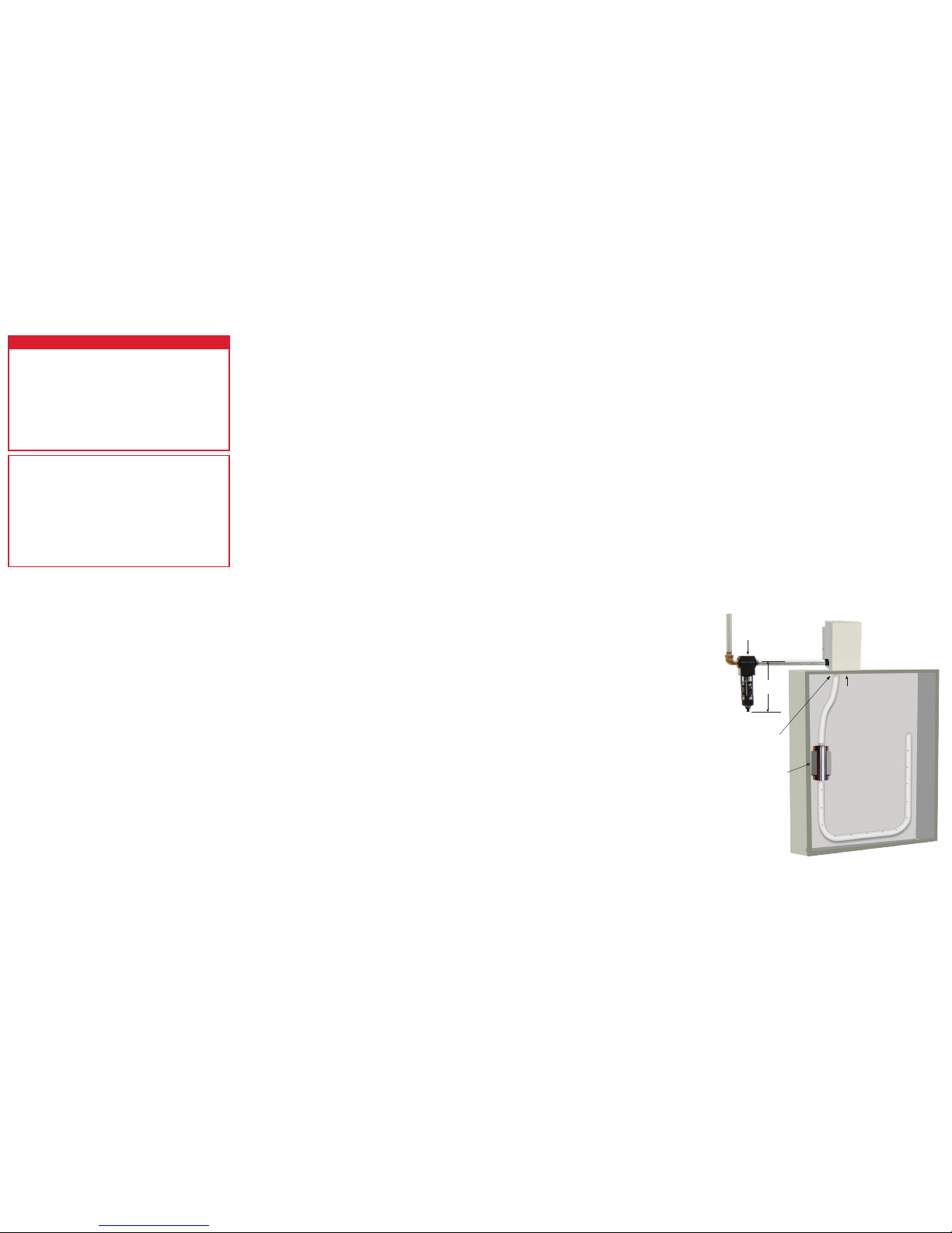
VORTEX A/C TYPE 4/4X
(SHOWN TOP MOUNTED ON CUSTOMER’S ENCLOSURE)
Hole 1-15/16” (49 mm)
1-3/4” (44 mm) diameter
x 3-19/32” (91 mm) long
muffler and mounting
clamps
Vent Air
Filter
5-7/8”
(149 mm)
 Loading...