

nvent Raychem NGC-30-CR, Raychem NGC-30-CVM, Raychem NGC-30-CRM, Raychem NGC-30-CRMS, Raychem NGC-30-CTM Installation Instructions Manual
Installation Instructions
Montageanleitung
Instructions d’installation
NGC-30-CR
NGC-30-CRM
NGC-30-CRMS
NGC-30-CTM
NGC-30-CVM

For English text, go to page 3
Für Deutsch, siehe Seite 11
Pour la version française, voir page 19
nVent.com | 3nVent.com | 3
INSTALLATION INSTRUCTIONS
Description
The nVent RAYCHEM NGC-30-CRM/-CRMS and NGC-30-CTM
provide ground-fault and line current sensing, alarming, switching
and RTD inputs for five heat-tracing circuits when used with the
NGC-UIT. The NGC-30-CRM is used to control Electromechanical
Relays (EMRs) and the NGC-30-CRMS is used to control Solid
State Relays (SSRs).
Tools Required
• Screw driver small blade - standard • Wire cutters
• RJ11 stripping/crimping tool • RJ11 connectors
Additional Materials
• Power supply - 12 Vdc @ 400 mA-per NGC-30-CRM/-CRMS
board
• RJ11 4 conductor cable
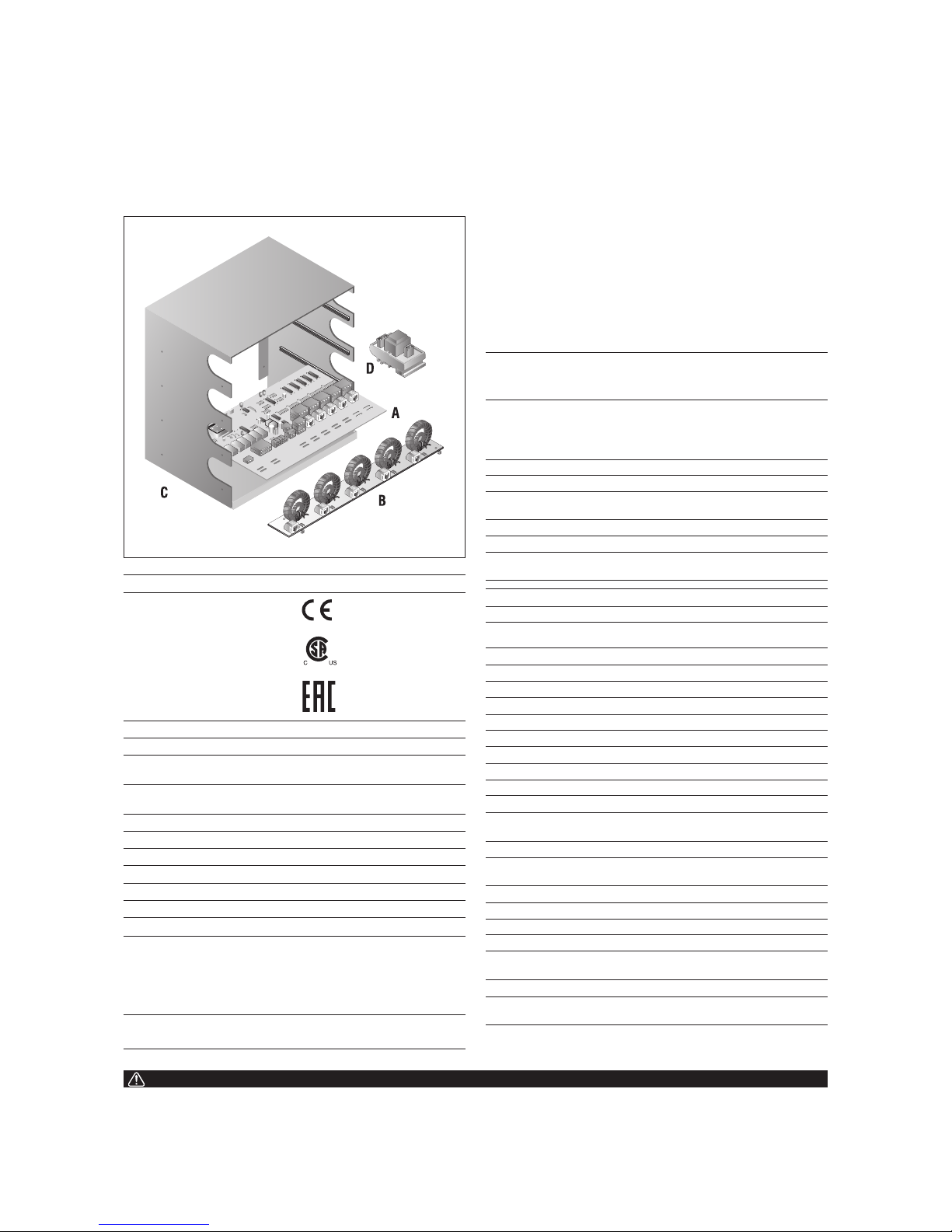
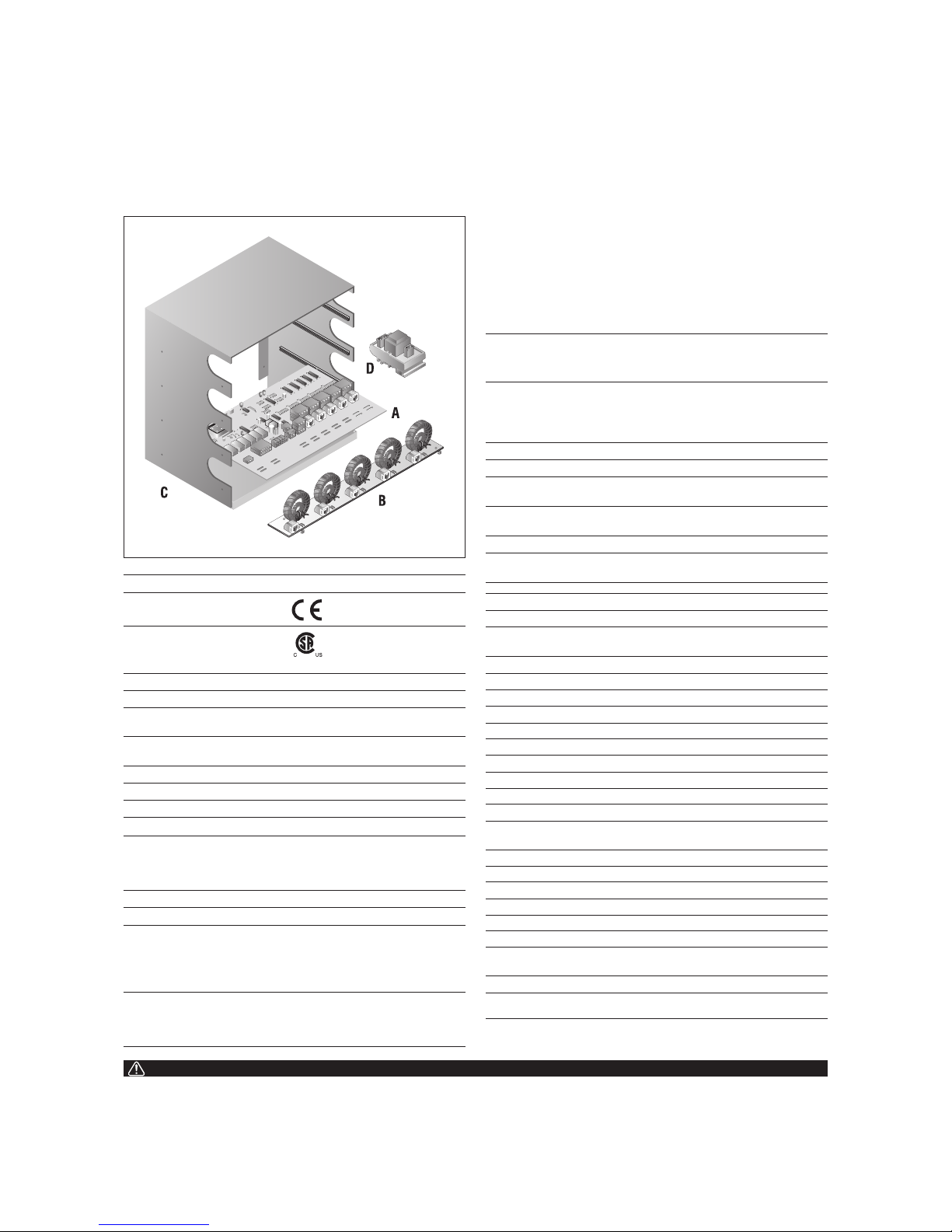
Kit Contents
Item Qty Description
A 1 NGC-30-CRM or CRMS (card rack module with
connectors)
B 1 NGC-30-CTM (current transformer module)
C 1 NGC-30-CR (card rack)
D 1 NGC-30-CVM (voltage monitoring module) -
optional
This component is an electrical device that must
be installed correctly to ensure proper operation
and to prevent shock or fire. Read these important
warnings and carefully follow all of the installation
instructions.
• Component approvals and performance are
based on the use of nVent-specified parts only.
Do not use substitute parts.
• Keep components dry before and during
installation.
• Leave these instructions with the end user for
reference and future use.
For technical support, call nVent at
+ 00 32 16 213511 or your local representative.
WARNING
NGC-30-CR
NGC-30-CRM
NGC-30-CRMS
NGC-30-CTM
NGC-30-CVM
CONTROL AND MONITORING MODULES FOR USE
WITH THE NVENT RAYCHEM NGC-30
General
Approvals/Certifications
Non-hazardous Locations
Hazardous Locations
Class I, Div. 2, Groups A,B,C,D
Ex nC IIC T5
Class I, Zone 2, AEx nC IIC T5
Supply Voltage 12 Vdc ± 10%
Internal power consumption < 5 W per NGC-30-CRM/-CRMS
Ambient operating temperature –40ºF to 140ºF (–40ºC to
60ºC)
Ambient storage temperature –40ºF to 167ºF (–40ºC to
75ºC)
Environment PD2, CAT III
Max. altitude 2000 m
Humidity 0 – 90% non-condensing
Electromagnetic Compatibility
Immunity Heavy Industrial
Emission Industrial Environment
Temperature Sensors
Type 100-ohm platinum RTD, 3-wire,
α = 0.00385 ohms/ohm/ºC.
Can be extended with a
3-conductor shielded cable
of 20 ohm maximum per
conductor
Quantity Up to five wired directly to
each NGC-30-CRM/-CRMS
Class I, Div. 2, Groups A,B,C,D
Ex nC IIC T5
Class I, Zone 2, AEx nC IIC T5
(Russia, Kazakhstan, Belarus)
For other countries
contact your local nVent
representative.
Current Sensors
Mounting Din Rail – 35 mm
Quantity per NGC-30-CTM Five for ground-current measurement
Five for line current measurement
Line Current Sensors
Max current 60 A
Accuracy ± 2% of reading
Ground Fault Sensor
Range 10 – 200 mA
Accuracy ± 4% of range at 30 A line current
Voltage Sensor
Range 80 – 290 Vac 50/60 Hz
Accuracy ± 1% of span
Outputs
CRM output relays Form A 3-Amp @ 277 Vac max 50/60
Hz
CRMS SSR outputs 12 Vdc @ 30 mA max per output
Alarm Relay Form C 3-Amp @ 277 Vac max 50/60
Hz
Communication to NGC-UIT
Type 2 wire RS-485
Cable One shielded twisted pair
Length 4000 ft. (1200 M) maximum
Quantity Up to 52* NGC-30-CRM/-CRMS may
be connected to one NGC-UIT
Connection Terminals
Power supply/Pilot Relay/
RTD/Comm Port (RS485)
0.8 - 3.3 mm
2
* May require repeaters
4 | nVent.com4 | nVent.com
NGC-30-CRM/-CRMS INSTALLATION INSTRUCTIONS
CLEANING INSTRUCTIONS
If dust accumulates on the NGC-30-CRM/-CRMS circuit board use
dried compressed air to remove the dust. Turn off all power to the
NGC-30 panel. Carefully disconnect all cables from a single NGC30-CRM/-CRMS card, making sure to label cables so that they can
be reconnected after board cleaning. Wear an anti-static wrist
strap connected to ground in order to avoid component damage.
Remove the CRM/CRMS circuit card from the card cage and place
on a clean lint-free surface.
Use dry compressed air from a can for cleaning circuit boards.
(Avoid factory compressed air since it may contain enough
moisture or oil to cause permanent damage.) Use short quick
blasts to remove dust build-up as necessary. After cleaning,
replace the CRM/CRMS in the same card cage position and
reconnect all cables. Remove only one card at a time for cleaning
to avoid any problems during re-installation.
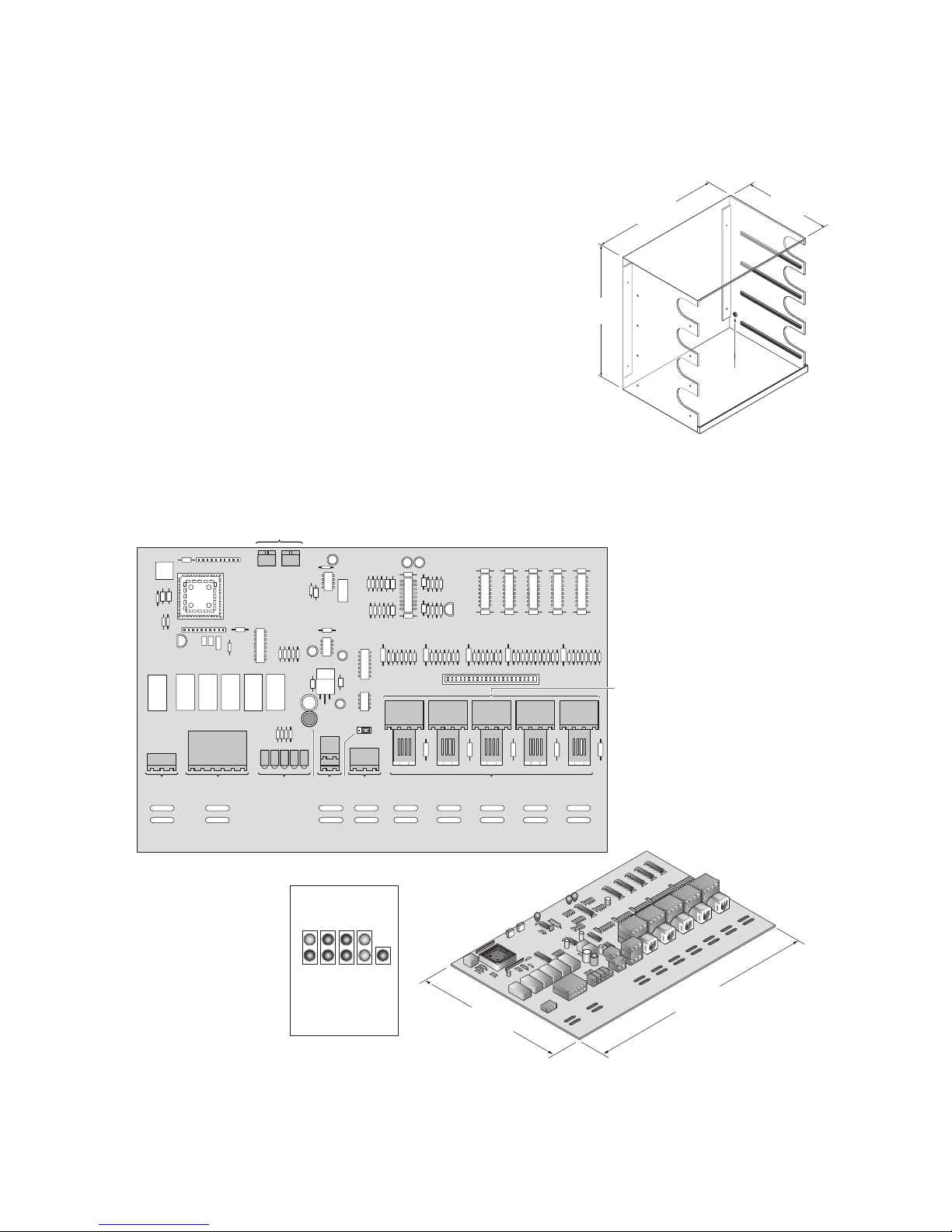
NGC-30-CR INSTALLATION INSTRUCTIONS
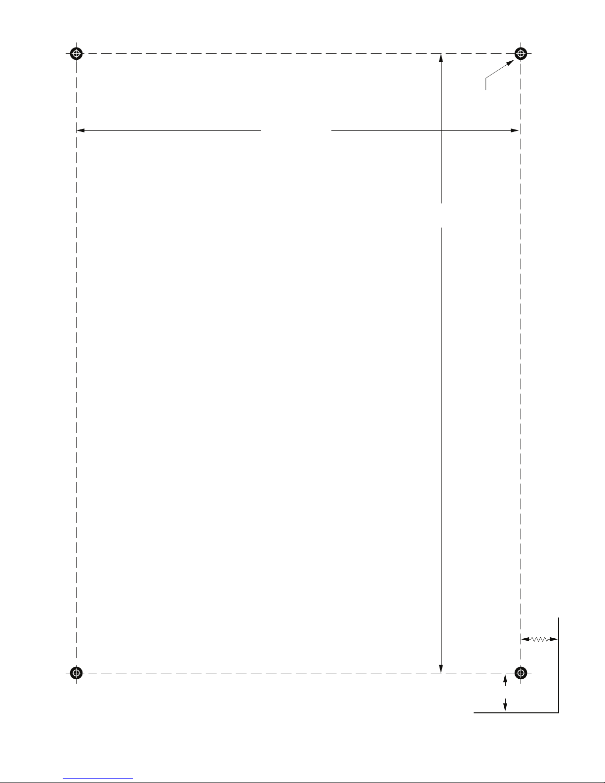
Mounting of Card Rack
Use the mounting template (on page 7) to mount the rack on a
panel backplane. There are four holes (0,48 cm dia.) to secure it
to the mounting surface using #8 screws.
Once the card
rack is installed,
a earth bonding
wire must be
connected to the
card rack using
the ground screw
provided.
Note: The card
rack must be
installed on a
non-combustible
surface.
279 mm
(10.97")
283 mm
(11.15")
183 mm
(7.20")
Grounding
screw
874561
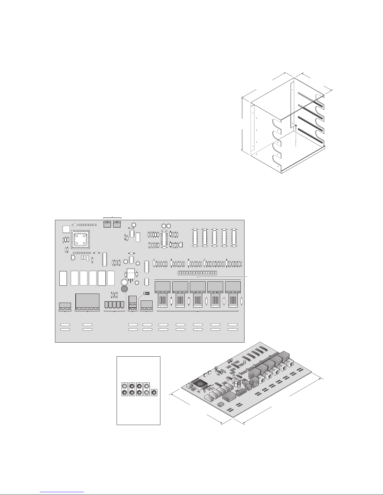
1
Alarm output
2
Relay outputs (5x)
3
LEDs (9x)
4
Fuse
5
12 Vdc Inputs (2x)
23
bk
9
6
End of Line (EOL) jumper
7
RS-485 Communications
8
Line & ground-fault sensor
inputs (5x)
9
RTD Inputs
bk
Address Switches
Power
Relay 1
Relay 3
Tx
Alarm
Relay 2
Relay 4
Rx
Relay 5
LED functions
NGC-30-CRM/CRMS
TB 12
MSB LSB
TB 7 TB 6
TB 13 TB 14 TB 15 TB 16 TB 17
TB 1 TB 2 TB 3 TB 4 TB 5
TB 19
1 2 3
273 mm
(10.75")
178 mm
(7.00")
nVent.com | 5nVent.com | 5
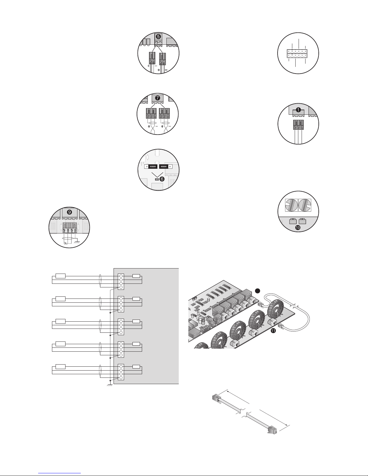
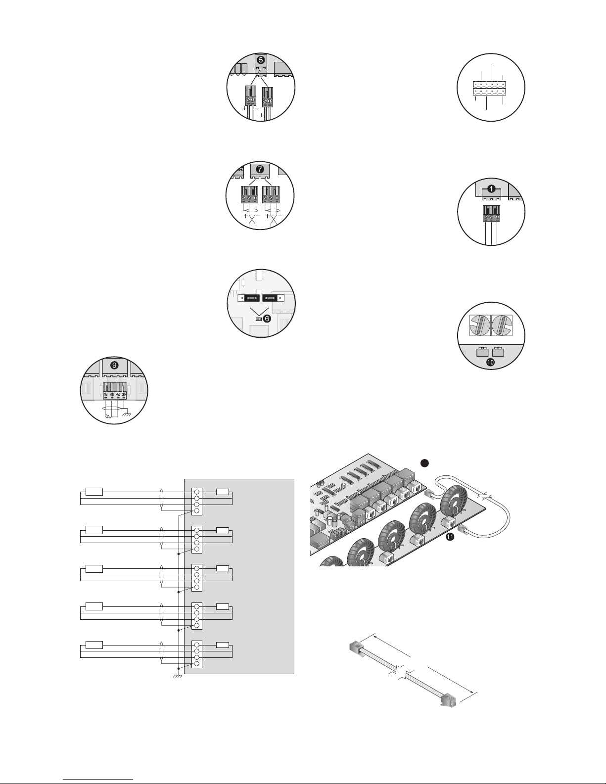
Power Supply
The power supply connector (TB19) is a
dual two pin connector. Either connector
allows for power in (pin #1 (+), pin #2 (–)
and bussing of power to other NGC-30CRM modules).
Note: Power supply must be sized correctly
based on the number of NGC-30-CRM/CRMS modules.
RS-485 Communications
The RS-485 connector (TB6) is a dual three
pin connector. Either connector allows for
RS-485 input signals (pin #1 (shield), pin
#2 (+), pin #3 (–)) and bussing of RS485
signal to other NGC-30-CRM modules.
End of Line (EOL) Jumper
If this device (NGC-30-CRM/-CRMS) is the
last device in the RS-485 network, the J1
jumper needs to be moved from terminals 2
& 3 to terminals 1 & 2.
RTD Inputs – Ordinary Area
1234
3 wire RTDs with shield may be connected
to RTD Ch1 thru Ch 5 (TB1 - TB5). The two
common wires (usually red, red) are
connected to terminals 2 & 3, the source
(usually white) to terminal 1 and the braid
to terminal 4 (earth ground).
Note: RTD's are not required if monitoring
current/ground-faults only or if RTD's are
connected via MONI-RMM2s.
1
2
3
4
1DTR 1DTR
dleihS dleihS
RTD connected directly to CRM board
RTD
1
2
3
4
2DTR 2DTR
dleihS dleihS
DTR DTR
1
2
3
4
3DTR 3DTR
dleihS dleihS
DTR DTR
1
2
3
4
4DTR 4DTR
dleihS dleihS
DTR DTR
1
2
3
4
5DTR 5DTR
dleihS dleihS
Chassis Ground
DTR DTR
CRM
PCB
Relay Output Connections to
Contactors or Solid State Devices
(TB7)
This connector switches voltage to the
contactor coils or solid state relays. The
pilot relay will switch the supply voltage (up
to 277 Vac) to the contactor coil (using an
NGC-30-CRM) or 12 Vdc to the solid state
device (using an NGC-30-CRMS).
Refer to system layout diagram for detail wiring.
Common Alarm
The common alarm terminal block (TB12)
provides a form C dry contact, rated at
277Vac max (3A).
When the RAYCHEM NGC-30 system is
powered on, the common alarm relay coil
is energized and pin 2 is connected to
pin 1(common). This is the "No Alarm"
condition for the CRM/CRMS board.
If the alarm occurs, or the CRM/CRMS
board loses power, the relay coil is
de-energized and pin 1 (common) is
disconnected from pin 2 and connected to
pin 3 to indicate an alarm condition exits.
Address Switches (SW1 & SW2)
Each NGC-30-CRM/-CRMS must have a
unique communication address selected.
The valid address switch range when using
the NGC-UIT is 1-99. SW1 is the ones digit
(0–9) and SW2 is the tens digit (0 or 9).
Note: When adding an NGC-30-CRM/CRMS to the system, you must perform a
network update at the NGC-UIT.
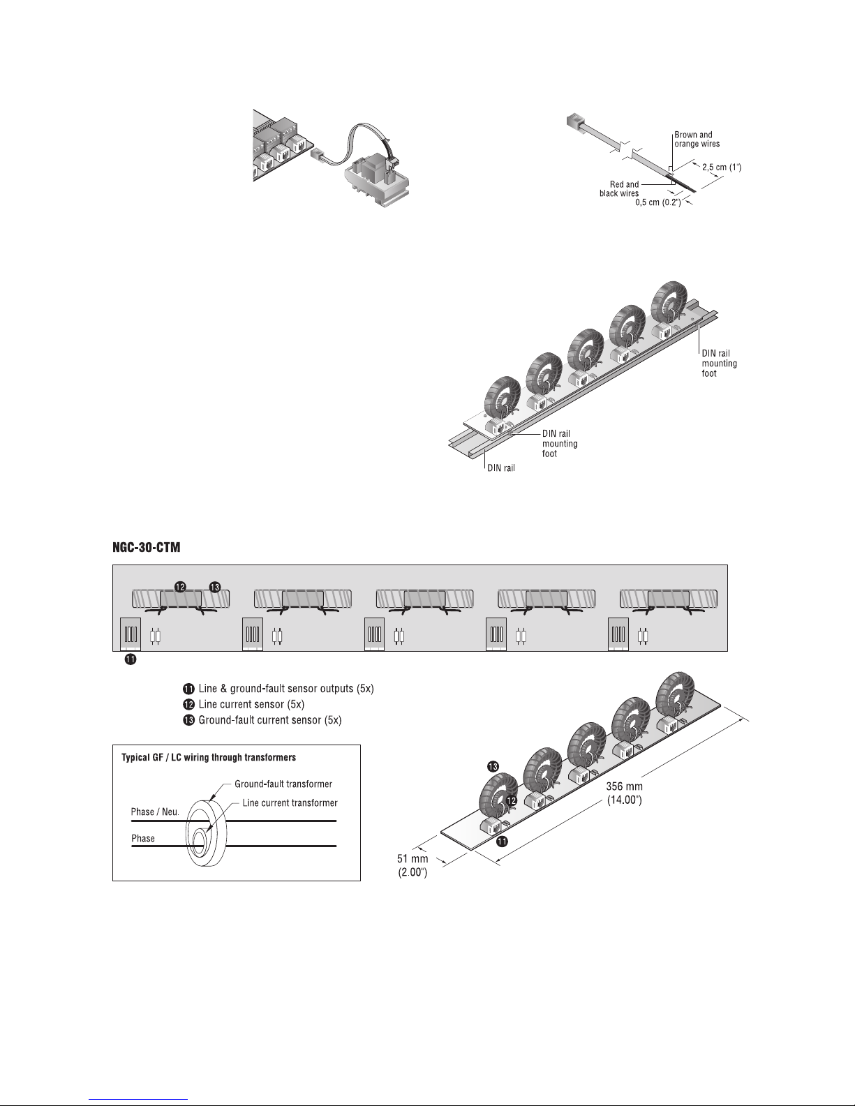
Ground-Fault/Line Current Sensors
Connections from NGC-30-CRM/-CRMS to NGC-30-CTM.
Using an RJ11 connector/cable assembly, connect one end to
an RJ11 input (TB13-TB17) and the other end to the appropriate
NGC-30-CTM RJ11 connector.
Typical connection
(1 of 5)
8
Ground-Fault/Line Current Cable Assembly
Cables are not available as loose item. They need to be created by
the project team while assembling the panel.
(L)
12
12
123123
Normal
position
End of Line
position
3
2
1
3
2
1
12-RLY4
6-RLY5
10-RLY 3
8-RLY2
123456
78910 11 12
3-RLY1
1-COM
321
N.O.
N.C.
COM
LSBMSB
SW1SW2
3
8
Relay "No Alarm"
Condition
6 | nVent.com6 | nVent.com
Mounting of NGC-30-CTM
Each NGC-30-CTM mounts on a DIN 35 rail. It should be located
between the circuit breaker or terminal block and contactor or SSR in
the panel.
NGC-30-CTM INSTALLATION INSTRUCTIONS
Optional Voltage Sensor
The optional voltage sensor
can monitor 80 – 290 Vac.
This voltage connects to
one of the five line current/
ground-fault inputs on the
NGC-30-CRM.
Note: By using the optional
voltage sensor, you lose the
ability to monitor the groundfault and current for that
circuit.
Cable Preparation
Notes:
1. Cut one end off of
a ground-fault /line
current cable.
2. Strip insulation approx.
2,5 cm from cut end.
3. Strip the red and black
wire insulation approx.
0,5 cm.
4. Connect red and black
wire to the two position
terminal plug. No need to be concerned about polarity.
5. Trim brown and orange wires from cut end.
nVent.com | 7nVent.com | 7
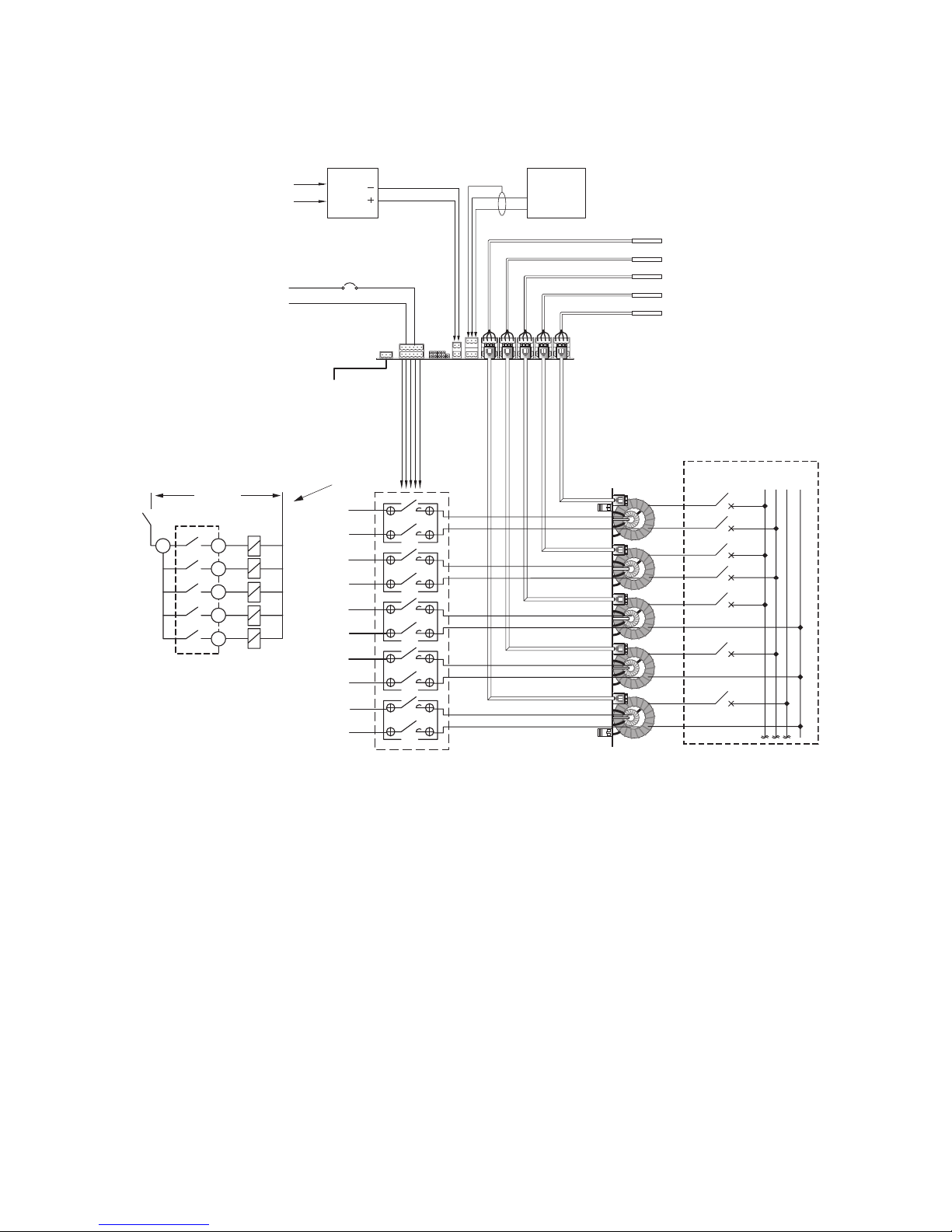
AC voltage up to 277 Vac
To heater's
power junction box
Alarm relay output
230 Vac
contctor power
L
N
NGC-30-CRM
NGC-30-CTM
Distribution panel board
with standard circuit breakers
System Layout NGC-30-CRM
12Vdc
Power
Supply
RTDs
230 Vac in
NGC-UIT
Touch
Screen
5
4
3
2
6
12
10
8
3
1
Relay drivers
230 Vac
LN
Pilot relays
located on
circuit board
Contactor
coils
To contactor coils
(see detail)
N
ø1ø3ø
2
1
SYSTEM LAYOUT NGC-30-CRM

8 | nVent.com8 | nVent.com
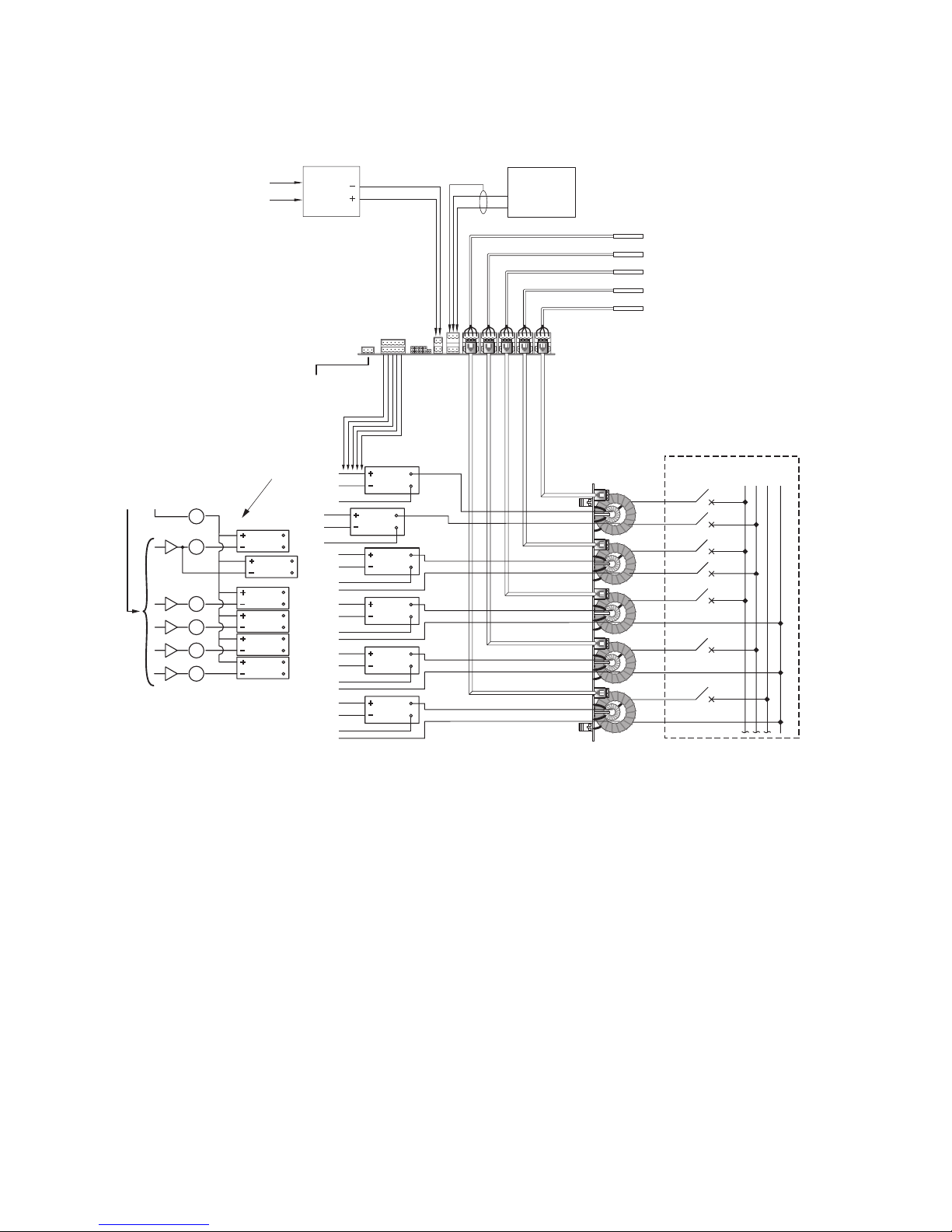
Note: 12Vdc power provided
by NGC-30-CRMS board
12Vdc
Power
Supply
NGC-30-CRMS
NGC-30-CTM
Distribution panel board
with standard circuit breakers
System Layout NGC-30-CRMS
230 Vac in
N
ø1ø3ø
2
SSR
SSR
SSR
SSR
SSR
SSR
SSR
SSR
SSR
SSR
SSR
AC voltage up to 277 Vac
Alarm relay output
Internal 12 Vdc
SSR power
6
5
12
10
8
3
1
4
3
2
1
Output driver
Internal
12 Vdc
+–
SSR
To SSR DC input
(see detail)
To heater’s
power junction box
(typical 5)
NGC-UIT
Touch
Screen
RTDs
SYSTEM LAYOUT NGC-30-CRMS
nVent.com | 9nVent.com | 9
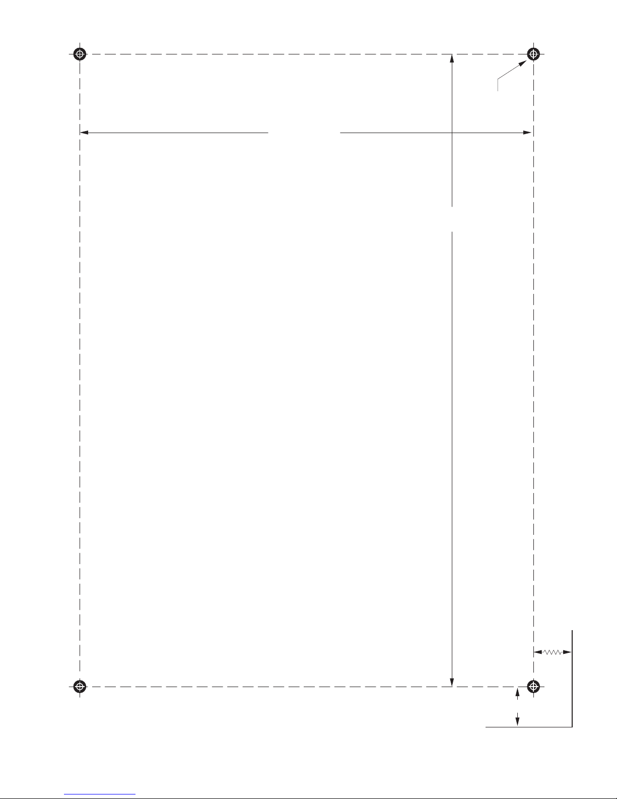
18 cm (7.00")
25 cm (9.75")
1,5 cm (0.625")
6,2 cm (2.4")
ø 0,5 cm
(0.188")
Top of Card Rack
NGC-30-CR Wall mounted hole template
(Note:
Ensure the printed template has scaled correctly.

10 | nVent.com10 | nVent.com
GENERAL INSTALLATION INSTRUCTIONS
1. The NGC-30 components must be installed:
• In compliance with all local electrical and safety codes
• In an enclosure suitable for the application environment.
When used in hazardous (Class I, Div. 2 or Zone 2) locations,
aminimum IP54 enclosure is required.
2. The NGC-30 components must be protected by external
overcurrent and disconnect devices. This may be a circuit
breaker or a combination of disconnect switch and fuses.
The disconnect device:
• Must disconnect all ungrounded, current-carrying conductors
• Should be located in close proximity to the equipment
• Be within easy reach of the Operator
• Be marked as the disconnecting device for the equipment
3. Supply wiring insulation must be rated for the highest voltage
and temperature to be encountered in the application.
Conductors must be sized for the application and be protected
by an external overcurrent device.
4. Some wiring configurations will use more than one power
source and all must be de-energized prior to performing any
maintenance on a controller circuit.
5. Protection provided by this equipment may be impaired if the
device is used outside of its ratings or for applications other
than is intended.
6. Always be sure that the intended location is classified as an
area for which the product is approved.
7. CRM(S) and CTM modules must be handled with care when
installed in a panel. Components should not be subject to
mechanical stress.
8. Wear an anti-static wrist strap connected to ground in order to
avoid component damage when installing the CRM(S) or CTM
modules.
CONDUCTED AND RADIATED EMISSIONS STATEMENT OF COMPLIANCE
This equipment has been tested and found to comply with the
limits for a Class A digital device, pursuant to Part 15 of the
FCC Rules. These limits are designed to provide reasonable
protection against harmful interference in a residential
installation. This equipment generates, uses and can radiate radio
frequency energy and, if not installed and used in accordance
with the instructions, may cause harmful interference to radio
communications. However, there is no guarantee that interference
will not occur in a particular installation. If this equipment does
cause harmful interference to radio or television reception, which
can be determined by turning the equipment off and on, the user
is encouraged to try to correct the interference by one or more of
the following measures:
– Reorient or relocate the receiving antenna.
– Increase the separation between the equipment and receiver.
– Connect the equipment into an outlet on a circuit different
from that to which the receiver is connected.
– Consult the dealer or an experienced radio/TV technician for
help.
This Class A digital apparatus complies with Canadian ICES-003.

nVent.com | 11nVent.com | 11
MONTAGEANLEITUNG
Beschreibung
Das nVent RAYCHEM NGC-30 ist ein elektronisches
Mehrkanalsystem zurRegelung und Überwachung von
Begleitheizungssystemen. Es findet beispielsweise Anwendung
bei Prozesstemperaturhaltung und Frostschutz an Rohrleitungen.
Die Systeme NGC-30-CRM/-CRMS und NGC-30-CTM beinhalten
die Fehlerstrom- und Heizstromüberwachung sowie Alarm-,
Schalt- und Fühlereingänge für fünf Heizkreise. Die Visualiserung
erfolgt über das Touchpanel NGC-30-UIT. Das NGC-30-CRM
steuert die elektromechanischen Relais (EMR), das NGC-30-CRMS
die elektronischen Lastrelais (SSRs).
Erforderliche Werkzeuge
• 3 mm Längsschlitzschraubendreher • Seitenschneider
• RJ11-Abisolier-/Crimp-Werkzeug • RJ11-Stecker
Weiteres Material
• Netzteil – DC 12 V bei 400 mA pro NGC-30-CRM/-CRMS-Karte
• RJ11-Kabel mit vier Leitern
Lieferumfang
Position Menge Beschreibung
A 1 NGC-30-CRM oder CRMS (Steckmodul für
5Heizkreise)
B 1 NGC-30-CTM (Stromwandlermodul)
C 1 NGC-30-CR (Baugruppenträger)
D 1 NGC-30-CVM
(Spannungsüberwachungsmodul) – optional
Bei dieser Komponente handelt es sich um ein
elektrisches Gerät, welches entsprechend den
Vorgaben eingebaut und betrieben werden muss,
damit der einwandfreie Betrieb sichergestellt ist
und die Gefahr eines Stromschlags oder eines
Brandes ausgeschlossen werden kann. Lesen Sie
diese wichtigen Warnhinweise, und befolgen Sie alle
Montageanweisungen genau.
• Zulassungen und Leistungsangaben gelten nur,
wenn Originalteile von nVent verwendet werden.
Verwenden Sie keine Fremdkomponenten.
• Komponenten vor und während der Montage
trocken halten.
• Übergeben Sie diese Montageanleitung an den
Betreiber der Anlage.
Falls Sie technische Unterstützung benötigen,
wenden Sie sich an nVent unter der
Telefonnummer+ 00 32 16 213511 oder an einen
Vertreter in Ihrer Region.
WARNUNG
NGC-30-CR
NGC-30-CRM
NGC-30-CRMS
NGC-30-CTM
NGC-30-CVM
REGEL- UND ÜBERWACHUNGSMODULE ZUM
NVENT RAYCHEM NGC-30
Allgemeines
Zulassungen/Zertifizierungen
Nicht-Ex-Bereiche
Explosionsgefährdete
Bereiche
Klasse I, Div. 2, Gruppen A,B,C,D
Ex nC IIC T5
Klasse I, Zone 2, AEx nC IIC T5
Betriebsspannung 12 Vdc ± 10%
Interne Leistungsaufnahme < 5 W pro NGC-30-CRM/-CRMS
Einsatztemperaturbereich –40ºC bis 60ºC (–40ºF to
140ºF)
Lagertemperaturbereich –40ºC bis 75ºC (–40ºF to
167ºF)
Umgebungsbedingungen PD2, CAT III
Max. Höhe 2000 m
Luftfeuchtigkeit 0 – 90 % nicht kondensierend
Elektromagnetische Verträglichkeit
Störaussendung Nach Klasse A
(Industrieumgebungen).
Entspricht CE-Standard
EN 61000-6-4:2001
Störfestigkeit Nach CE 61000-6-2
Temperatursensoren
Typ 100-Ohm-Platinfühler PT100 in
3-Leitertechnik.
α = 0,00385 Ohm/Ohm/ºC
verlängerbar mit einem
geschirmten 3-adrigem Kabel,
max. 20 Ohm pro Leiter
Anzahl
Bis zu 5 PT100 (3-Leiter) können
direkt an einem NGC-30-CRM/-
CRMS angeschlossen werden
T5
T5
Stromwandler
Montage DIN-Schiene – 35 mm
Anzahl pro NGC-30-CTM Fünf zur Fehlerstrommessung Fünf
zur Heizstromüberwachung
Stromwandler für Fehlerstrom
Max. Strom 60 A
Genauigkeit ± 2% des angezeigten Wertes
Stromwandler für Heizstrom
Bereich 10 – 200 mA
Genauigkeit ± 2% des Bereichs
Spannungssensor
Bereich AC 80 – 290 V, 50/60 Hz
Genauigkeit ± 1 % des Bereichs
Ausgänge
CRM-Ausgangsrelais Form A, 3 A bei AC 277 V max.
50/60 Hz
CRMS SSR-Ausgänge DC 12 V bei 30 mA max. pro Ausgang
Alarmrelais Einpolige Kontakte 3 A bei AC 277 V
max. 50/60 Hz
Kommunikation mit NGC-UIT
Typ RS-485, zweiadrig
Kabel geschirmtes Twisted Pair-Kabel
(verdrillte Leitung)
Länge max. 1.200 m
Anzahl Bis zu 52* NGC-30-CRM/-
CRMS können an ein NGC-UIT
angeschlossen werden
Anschlussklemmen
Netzteil/Steuerrelais/Fühler/
Comm-Port (RS485)
0,8 - 3,3 mm
2
* Evtl. sind Repeater erforderlich

12 | nVent.com
MONTAGEANLEITUNG NGC-30-CRM/CRMS
HINWEIS ZUR REINIGUNG
Falls sich auf der NGC-30-CRM/-CRMS-Karte Staub ansammelt,
können Sie diesen mit trockener Druckluft entfernen. Trennen
Sie den NGC-30-Schaltschrank von der Stromversorgung.
Trennen Sie vorsichtig alle Kabel von einer NGC-30-CRM/-CRMSKarte. Kennzeichnen Sie dabei die Kabel so, dass sie nach
der Reinigung der Karte wieder richtig angeschlossen werden
können. Tragen Sie ein mit Masse verbundenes AntistatikArmband, damit die Komponenten nicht geschädigt werden
(elektrostatische Entladung). Entfernen Sie die CRM/CRMS-Karte
aus dem Baugruppenträger, und legen Sie sie auf einer sauberen,
fusselfreien Oberfläche ab.
Reinigen Sie die Karten mit trockener Druckluft. (Vermeiden Sie
Fabrikdruckluft, da diese verhältnismäßig viel Feuchtigkeit oder
Öl enthalten und dauerhafte Schäden verursachen kann.)
Beseitigen Sie den angesammelten Staub mit kurzen,
schnellen Sprühstößen. Setzen Sie die CRM/CRMS-Karte
nach der Reinigung wieder in die ursprüngliche Position in den
Baugruppenträger ein, und schließen Sie wieder alle Kabel an.
Entfernen Sie die Karten einzeln nacheinander, um sie zu reinigen.
So treten beim Wiedereinsetzen keine Probleme auf
MONTAGEANLEITUNG NGC-30-CR
Montieren des Baugruppenträgers
Montieren Sie den Baugruppenträger mit Hilfe einer
Montageschablone (auf Seite 7) an der Rückwand des
Schaltschranks. Für die Befestigung des Baugruppenträgers sind
vier Bohrungen Ω 4,8 mm vorgesehen.
Nach dem
Einbau des
Baugruppenträgers
muss dieser
entsprechend den
Vorgaben an der
entsprechenden
Erdungsschraube
geerdet werden.
Anmerkung: Der
Baugruppenträger
ist auf einer
nicht brennbaren
Oberfläche zu
montieren.
279 mm
(10.97")
283 mm
(11.15")
183 mm
(7.20")
Erdungsschraube
bk
Betrieb
Relais 1
Relais 3
Senden Tx
Alarm
Relais 2
Relais 4
Emphang Rx
Relais 5
LED Funktionen
NGC-30-CRM/CRMS
TB 12
MSB LSB
TB 7 TB 6
TB 13 TB 14 TB 15 TB 16 TB 17
TB 1 TB 2 TB 3 TB 4 TB 5
TB 19
1 2 3
273 mm
(10.75")
178 mm
(7.00")
1
2
3
4
56
7
8
9
1
Alarmausgang
2
Relaisausgänge (5x)
3
LEDs (9x)
4
Sicherung
5
DC 12 V-Eingänge (2x)
6
Abschlusswiderstand
7
RS-485-Kommunikation
8
Heiz- und FehlerstromEingänge (5x)
9
Fühlereingänge
bk
Schwarze Adressschalter

nVent.com | 13
Spannungsversorgung
Beim Anschluss (TB19) handelt es sich
um zwei zweipolige Stecker. An beiden
Steckern besteht die Möglichkeit die
Spannungsversorgung (Kontakt 1 (+),
Kontakt 2 (–)) anzuschließen, bzw.
die anderen NGC-30-CRM-Module mit
Spannung zu versorgen.
Anmerkung: Die Spannungsversorgung
muss genau auf die Anzahl der
NGC-30-CRM/-CRMS-Module abgestimmt werden.
RS-485 Kommunikation
Bei dem RS-485-Anschluss (TB6) handelt
es sich um zwei dreipolige Stecker.
Es kann ein RS-485-Eingangssignale
(Kontakt 1 (Schirmung), Kontakt 2 (+),
Kontakt 3 (–)) angeschlossen werden,
bzw. das RS485-Signal wird zu den anderen
NGC-30-CRM-Modulen weitergeleitet.
Abschlusswiderstand
Wenn dieses Gerät (NGC-30-CRM/-CRMS)
das letzte Gerät im RS-485-Netzwerk ist,
muss der Jumper J1 von den Anschlüssen
2und 3 zu den Anschlüssen
1 und 2 versetzt werden.
Fühlereingänge – Nicht-Ex-Bereiche
1234
Pt 100 in 3-Leitertechnik mit Schirmung
können an den Fühlerkanal TB1 - TB5
angeschlossen werden. Die beiden
gemeinsamen Drähte (üblicherweise rot,
rot) werden mit den Anschlüssen 2 und 3
verbunden, die Quelle (üblicherweise weiß)
mit Anschluss 1 und das Geflecht mit
Anschluss 4 (Masse).
Anmerkung: Es sind keine Fühler
erforderlich, wenn nur der Strom/
Fehlerstrom überwacht wird oder wenn die
Fühler über MONI-RMM2 angeschlossen
sind.
1
2
3
4
1DTR1DTR
RTD wird direct am CRM angeschlossen
1
2
3
4
2DTR2DTR
1
2
3
4
3DTR3DTR
1
2
3
4
4DTR4DTR
1
2
3
4
5DTR5DTR
Gehause Erde
CRM
PCB
Abschirmung
Abschirmung
Abschirmung
Abschirmung
Abschirmung
Pt 100
Pt 100
Pt 100
Pt 100
Pt 100
Ansteuerung von Schützen oder
elektronischen Lastrelais (TB7)
Dieser Ausgang schaltet die
Spannung zu den Schützspulen oder
elektronischen Lastrelais (Solid State
Relays). Das Steuerrelais schaltet
die Versorgungsspannung (bis zu
AC 277 V) zur Schützspule (mit Hilfe
von NGC-30-CRM) oder DC 12 V zum
elektronischen Lastrelais (mit Hilfe von
NGC-30-CRMS) um. Die detaillierte Verdrahtung können Sie dem
Anschlussschema entnehmen.
Sammelstörmeldung
Der Sammelalarm-Anschlussblock (TB12)
liefert einen einpoligen Wechselkontakt
bei einer Nennspannung von max. AC 277
V (3 A). Beim Einschalten des Systems
RAYCHEM NGC-30 wird der Relaiskontakt
(Kontakt 1/Kontakt 2) geschlossen.
Der geschlossene Kontakt bedeutet
„KEIN ALARM“ für die jeweilige CRM/
CRMS-Karte. Bei einem Alarm, bzw. bei
einer Unterbrechung der CRM/CRMSSpannungsversorgung, fällt das Relais ab,
und Kontakt 1/Kontakt 2 wird geöffnet bzw.
Kontakt 1/Kontakt 3geschlossen.
Adresswahlschalter (SW1 und SW2)
Adresswahlschalter (SW1 und SW2)
Jedem NGC-30-CRM/-CRMS muss eine
eindeutige Adresse zugewiesen werden.
Der gültige Bereich Adresswahlschalters,
bei Verwendung des NGC-UIT, ist 1-99.
SW1 steht für die Einerstellen (0-9), SW2
für die Zehnerstellen (0 oder 9).
Anmerkung: Wenn ein NGC-30-CRM/CRMS zum System hinzugefügt
wird, müssen Sie am NGC-UIT eine
Netzwerkaktualisierung vornehmen.
Fehlerstrom-/ Heizstromwandler
Verbindungen vom NGC-30-CRM/-CRMS zum NGC-30-CTM.
Verbinden Sie den RJ11-Eingang (TB13-TB17) und den NGC-30CTM RJ11-Anschluss mit einem RJ11-Anschlusskabel.
Typischer Anschluss
(1 von 5)
8
Fehlerstrom-/ Heizstrom-Anschlusskabel
Kabel sind nicht lose erhältlich. Sie müssen vom Projektteam
während der Montage des Schaltschranks zusammengestellt
werden.
(L)
12
12
123123
Normal
position
End of Line
position
3
2
1
3
2
1
12-RLY4
6-RLY5
10-RLY 3
8-RLY2
123456
78910 11 12
3-RLY1
1-COM
321
N.O.
N.C.
COM
LSBMSB
SW1SW2
3
8
Relais Bedingung
„Kein Alarm“

14 | nVent.com
Montage des NGC-30-CTM
Jedes NGC-30-CTM wird auf einer DIN-35-Schiene montiert. Essollte
zwischen dem Schutzschalter oder der Klemmleiste
und dem Schütz oder Solid State Relay im Schaltschrank
montiert werden.
MONTAGE DES NGC-30-CTM
Optionaler Spannungssensor
Der optionale
Spannungssensor kann AC
80 - 290 V überwachen. Diese
Spannung wird mit einem der
fünf Leitungsstrom/Fehlerstromeingänge am
NGC-30-CRM verbunden.
Anmerkung: Wenn Sie den
optionalen Spannungssensor
verwenden, können Sie den
Fehler- und Heizstrom für
diesen Heizkreis nicht mehr
überwachen.
Vorbereitung des Kabels
Anmerkungen:
1. Schneiden Sie von
einem Fehlerstrom-/
Heizstromkabel ein
Ende ab.
2. Isolieren Sie am
abgeschnittenen
Kabelende ca. 2,5 cm ab.
3. Isolieren Sie am roten
und schwarzen Draht ca. 0,5 cm ab.
4. Schließen Sie den roten und schwarzen Draht an den
Anschlussklemmen des Spannungssensors an Dabei brauchen
Sie nicht auf die Polarität zu achten.
5. Schneiden Sie den braunen und orangefarbenen Draht ab.
DIN-Schiene
Montagefuß der
DIN-Schiene
Montagefuß der
DIN-Schiene

nVent.com | 15
Wechselstrom bis
zu AC 277 V
Zum Anschlusskasten
der Heizleitungung
Alarmrelaisausgang
AC 230 V
Steuerspannung
Leistungsschütze
L
N
NGC-30-CRM
NGC-30-CTM
Schaltschrank mit
standardmäßigen
Leitungs-Schutzschaltern
Netzteil
DC 12 V
Pt 100 Sensor/Fühler
230 Vac in
Touchscreen
NGC-UIT
5
4
3
2
6
12
10
8
3
1
Relaisansteuerung
230 Vac
LN
Steuerrelais
auf der Platine
Schützspulen
Zu Schützspulen
(siehe Detail)
N
ø1ø3ø
2
1
ANSCHLUSSSCHEMA – NGC-30-CRM
16 | nVent.com
Anmerkung: DC 12 V-Stromversorgung
wird von der NGC-30-CRMS-Karte
geliefert
Netzteil
DC 12 V
NGC-30-CRMS
NGC-30-CTM
Schaltschrank mit
standardmäßigen
Leitungs-Schutzschaltern
230 Vac in
N
ø1ø3ø
2
SSR
SSR
SSR
SSR
SSR
SSR
SSR
SSR
SSR
SSR
SSR
Wechselstrom bis
zu AC 277 V
Alarmrelaisausgang
Interne DC 12 V
SSR-Stromversorgung
6
5
12
10
8
3
1
4
3
2
1
Ausgangstreiber
Koppelrelais
Intern
12 Vdc
+
–
SSR
DC-Eingang
(siehe Detail)
Zum Anschusskasten
der Heizleitung
Pt100 Sensor/Fühler
Touchscreen
NGC-UIT
ANSCHLUSSSCHEMA – NGC-30-CRMS
nVent.com | 17
18 cm (7.00")
25 cm (9.75")
1,5 cm (0.625")
6,2 cm (2.4")
ø
0,5 cm
(0.188")
Oberseite des Baugruppenträgers
NGC-30-CR – Bohrungsschablone für die
Wandmontage
(Anmerkung: Achten Sie dara
uf, dass die gedruckte Schablone maßstabsgerecht ist.

18 | nVent.com
ALLGEMEINE MONTAGEANLEITUNG
1. Die NGC-30-Komponenten müssen installiert werden:
• Unter Einhaltung aller lokalen Vorschriften und
Sicherheitsrichtlinien
• In einem für die Anwendung geeigneten Gehäuse. Bei
Verwendung in Ex-Bereichen (Klasse I, Div. 2 oder Zone 2)
istmindestens ein IP54-Gehäuse erforderlich.
2. Die NGC-30-Komponenten sind durch externe Überstrom- und
Trennvorrichtungen zu schützen. Dabei kann es sich um einen
Schutzschalter oder eine Kombination aus Trennschalter und
Sicherungen handeln.
Die Trennvorrichtung:
• Muss alle nicht geerdeten, stromführenden Leiter trennen
• Sollte sich in unmittelbarer Nähe des Geräts befinden
• Muss für den Bediener leicht erreichbar sein
• Ist als Trennvorrichtung für das Gerät zu kennzeichnen
3. Die Verdrahtung ist entsprechend der vorgesehenen
Anschlussspannung bzw. des Nennstroms entsprechende
und der maximal auftretenden Temperatur auszulegen.
Die eingesetzten Anschlusskabel sind auf die Anwendung
abzustimmen und durch eine externe Überstromvorrichtung
zuschützen.
4. Einige Bauteile nutzen mehrere Stromquellen welche alle
abgeschaltet werden müssen, bevor Wartungsarbeiten
ausgeführt werden dürfen.
5. Der von dieser Vorrichtung ausgehende Schutz kann
beeinträchtigt werden, wenn die Nennwerte des Geräts
überschritten werden oder wenn das Gerät für andere als die
vorgesehenen Anwendungen verwendet wird.
6. Es ist stets darauf zu achten, dass das Produkt nur für
den Anwendungsfall eingesetzt wird, für welchen die
entsprechenden Zulassungen vorliegen.
7. Beim Einbau der Module CRM(S) und CTM in einen
Schaltschrank ist Sorgfalt geboten. Die Bauteile dürfen keiner
mechanischen Belastung ausgesetzt werden.
8. Tragen Sie beim Einbau der Module CRM(S) oder CTM ein
mit Masse verbundenes Antistatik-Armband, damit die
Komponenten nicht beschädigt werden.
ELEKTROMAGNETISCHE VERTRÄGLICHKEIT
– ERKLÄRUNG ÜBER DIE EINHALTUNG DER
GESETZLICHEN BESTIMMUNGEN
Dieses Gerät wurde getestet und entspricht den Grenzwerten für
digitale Geräte der Klasse A gemäß Teil 15 der FCC-Richtlinien.
Diese Grenzwerte wurden für einen angemessenen Schutz gegen
Störstrahlungen in Wohngebieten entwickelt. Dieses Gerät kann
Funkfrequenzenergie erzeugen, verwenden und abstrahlen. Wenn
es nicht gemäß den Anweisungen installiert und verwendet wird,
kann es Störstrahlungen bei Funkübertragungen hervorrufen. Es
kann jedoch nicht ausgeschlossen werden, dass bei bestimmten
Installationen doch Störstrahlungen auftreten. Falls dieses
Gerät den Radio- oder Fernsehempfang stört, was durch Ausund Einschalten des Geräts festgestellt werden kann, sollte
der Benutzer zur Behebung der Störung mindestens eine der
folgenden Maßnahmen ergreifen:
– Die Empfangsantenne neu ausrichten oder an einer anderen
Stelle aufstellen.
– Den Abstand zwischen dem Gerät und dem Empfänger
vergrößern.
– Das Gerät an eine andere Steckdose anschließen, die
nicht zu dem Schaltkreis gehört, an den der Empfänger
angeschlossen ist.
– Den Händler oder einen erfahrenen Radio-/Fernsehtechniker
um Hilfe bitten.
Dieses Gerät entspricht EN ICES-003.
nVent.com | 19
INSTRUCTIONS D’INSTALLATION
Description
Le nVent RAYCHEM NGC-30 est un système de régulation, de
surveillance et de distribution électrique pour les applications
de traçage multicircuit, spécialement conçu pour le maintien en
température des lignes de process et la mise hors gel. Les NGC30-CRM/-CRMS et NGC-30-CTM détectent les courants de fuite
et de ligne et assurent les fonctions d’alarme, de commutation
et d’entrées RTD pour cinq circuits de traçage en cas d’utilisation
avec le terminal d’interface utilisateur NGC-UIT. Le NGC-30-CRM
assure le contrôle des relais électromécaniques et le NGC-30CRMs, celui des relais statiques.
Outillage
• Tournevis fin - standard • Pince coupante
• Pince à dénuder/à sertir RJ11 • Câble RJ11
Matériaux supplémentaires
• Alimentation – 12 V cc @ 400 mA - par carte NGC-30-CRM/CRMS
• Câble conducteur RJ11 4 conducteurs
Contenu du kit
Réf. Qté Description
A 1 NGC-30-CRM ou CRMS (module Card Rack avec
connecteurs)
B 1 • NGC-30-CTM (module transformateur de
courant)
C 1 NGC-30-CR (Card Rack)
D 1 NGC-30-CVM (module de contrôle de tension) –
option
Ce composant est un équipement électrique qui doit
être installé dans les règles de l’art pour garantir
un fonctionnement correct et prévenir tout risque
d’électrocution ou d’incendie. Lire et respecter
scrupuleusement les instructions d’installation.
• Les agréments et performances des composants
sont basés sur l’utilisation exclusive de pièces
nVent spécifiées. Ne pas utiliser de pièces de
substitution.
• Conserver les composants à l’abri de l’humidité
avant et pendant l’installation.
• Remettez ces instructions à l’utilisateur final pour
consultation ultérieure.
Pour de l’assistance technique, appelez nVent au
+ 00 32 16 213511 ou contactez votre représentant.
AVERTISSEMENT
NGC-30-CR
NGC-30-CRM
NGC-30-CRMS
NGC-30-CTM
NGC-30-CVM
MODULES DE RÉGULATION ET SURVEILLANCE À
UTILISER AVEC NVENT RAYCHEM NGC-30
Généralités
Agréments/Certifications
Zones non explosibles
Zones explosibles
Classe I, Div. 2, Groupes A,B,C,D
Ex nC IIC T5
Classe I, Zone 2, AEx nC IIC T5
Tenssion d’alimentation 12 V cc ± 10%
Consommation interne < 5 W par NGC-30-CRM/-CRMS
Température ambiante de
service
–40ºC à 60ºC
Température ambiante de
stockage
–40ºC à 75ºC
Environnement PD2, CAT III
Altitude max. 2000 m
Humidité 0 - 90% sans condensation
Compatibilité électromagnétique
Émissions Testé selon Classe A
(environnements industriels).
Selon norme CE NE 61000-64:2001
Immunité Testé selon CE 61000-6-2
Sondes de température
Type RTD 100 Ω platine, 3 fils,
α = 0,00385 Ω/Ω/ºC. Extensible
à l’aide d’un câble blindé 3
conducteurs de max. 20 Ω par
conducteur
Quantity Jusqu’à 5 PT 100 3 conducteurs
connectées directement à
chaque
N GC-30-CRM/-CRMS
T5
T5
Capteur de courant
Intensité maximale 60 A
Précision
• Cinq pour mesure du courant de terre.
• Cinq pour mesure du courant de ligne.
Capteurs de courant de ligne
Max current 60 A
Accuracy ± 2% de la valeur
Capteur de défaut de terre
Plage 10 – 200 mA
Précision ± 2% de la plage
Capteur de tension
Plage 80 – 290 V ca 50/60 Hz
Précision ± 1% de la plage
Sorties
Relais sortie CRM Forme A 3 A @ 277 V ca max.
50/60Hz
Sorties SSR CRMS 12 V cc @ 30 mA max. par sortie
Relais d’alarme SPDT 3 A @ 277 V ca max. 50/60 Hz
Communication vers NGC-UIT
Type RS-485 bifilaire
Câble Un câble blindé à paire torsadée
Longueur Maximum 1200 m
Quantité Jusqu’à 52* NGC-30-CRM/-CRMS
peuvent être connectés à un NGC-UIT
Borniers de connexion
Alimentation/Relais pilote/
RTD/Port Comm (RS485)
0,8 - 3,3 mm
2
* Des répétiteurs peuvent être nécessaires
20 | nVent.com
INSTRUCTIONS D’INSTALLATION NGC-30-CRM/CRMS
NETTOYAGE
En cas d’accumulation de poussière sur les cartes NGC-30CRM/-CRMS, nettoyer à l’air comprimé sec. Mettre le panneau
NGC-30 hors tension. Déconnecter prudemment tous les câbles
d’une carte NGC-30-CRM/- CRMS, en veillant à les étiqueter
pour en faciliter le rebranchement après nettoyage. Porter un
bracelet antistatique relié à la terre pour éviter d’endommager les
composants. Retirer la carte CRM/CRMS de son logement
et posez-la sur une surface propre non pelucheuse.
Utiliser un aérosol d’air comprimé pour nettoyer les cartes (éviter
d’utiliser un compresseur industriel parce que l’air qu’il propulse
est susceptible de contenir de l’humidité ou de l’huile pouvant
endommager les composants). Respecter les instructions
d’utilisation noté sur l’aérosol. Procéder par à-coups pour éliminer
la poussière accumulée. Après nettoyage, remettre la carte
CRM/CRMS en place et rebrancher les câbles. Pour éviter tout
problème lors de la réinstallation, ne retirer qu’une seule carte
à la fois pour procéder à son nettoyage.
NOTICE D’INSTALLATION NGC-30-CR
Montage du Card Rack
Le gabarit de montage (page 7) permet de monter le rack sur le
panneau arrière de l’armoire électrique. Quatre trous de Ø 0,48 cm
permettent de le fixer à l’aide de vis #8.
Une fois le Card
Rack installé,
mettre à la terre
en connectant
un câble entre
le rack et la vis
prévue à cet effet.
Remarque:
Le rack doit être
installé sur une
surface non
combustible.
279 mm
(10.97")
283 mm
(11.15")
183 mm
(7.20")
Vis de mise
à la terre
1
Sortie d’alarme
2
Sorties relais (5x)
3
Diodes (9x)
4
Fusible
5
Entrées 12 V cc (2x)
bk
6
Cavalier fin de ligne (EOL)
7
Communications RS-485
8
Entrées sonde ligne et
défaut de terre (5x)
9
Entrées RTD
bk
Commutateurs d’adresse
Alimentation
Relais 1
Relais 3
Tx
Alarme
Relais 2
Relais 4
Rx
Relais 5
Fonctions diode
NGC-30-CRM/CRMS
TB 12
MSB LSB
TB 7 TB 6
TB 13 TB 14 TB 15 TB 16 TB 17
TB 1 TB 2 TB 3 TB 4 TB 5
TB 19
1 2 3
273 mm
(10.75")
178 mm
(7.00")
1
2
3
4
56
7
8
9
nVent.com | 21
Alimentation
L’alimentation s’effectue par un double
connecteur à deux broches (TB19). Chaque
connecteur assure l’entrée de l’alimentation
électrique (broche #1 (+), pin #2 (-) et
sert de bus d’alimentation vers d’autres
modules NGC-30-CRM).
Remarque: L’alimentation électrique doit
être dimensionnée en fonction du nombre
de modules NGC-30-CRM/-CRMS.
Communications RS-485
Le connecteur RS-485 (TB6) est un double
connecteur à trois broches. Chaque
connecteur prend en charge les signaux
d’entrée RS-485 (broche #1 (blindage),
broche #2 (+), broche #3 (–)) et sert de
bus de signal RS485 vers d’autres modules
NGC-30-CRM.
Cavalier fin de ligne (EOL)
Si le contrôleur est à la fin du réseau RS485,
le strap doit être retiré des bornes 2 & 3 et
placé entre les bornes 1 & 2.
Entrées RTD – zone ordinaire
1234
Des RTD à 3 brins et blindage peuvent être
connectés à RTD Ch1 via Ch 5 (TB1 - TB5).
Les deux conducteurs communs
(généralement rouge, rouge) se
connectent aux bornes 2 et 3, la source
(généralement blanc) à la borne 1 et la
tresse à la borne 4 (à la mise à la terre).
Remarque: les RTD ne sont pas
nécessaires en cas de seul contrôle du
courant d’alimentation ou de terre, ou
lorsque les sondes RTD sont connectées
via MONI-RMM2.
1
2
3
4
1DTR1DTR
RTD connectée directement à la carte CRM
1
2
3
4
2DTR2DTR
1
2
3
4
3DTR3DTR
1
2
3
4
4DTR4DTR
1
2
3
4
5DTR5DTR
Mise à la terre
CRM
PCB
Blindage
Blindage
Blindage
Blindage
Blindage
RTD
RTD
RTD
RTD
RTD
Connexions sortie relais vers
contacteurs ou relais statiques
(TB7)
Ce connecteur commute la tension vers
les bobinages des contacteurs ou vers
les relais électroniques. Le relais pilote
commute la tension d’alimentation (jusqu’à
277 V ca) vers le bobinage du contacteur
(via un NGC-30-CRM) ou du 12 V cc vers
les relais électroniques (via un NGC-30-CRMS).
Voir le schéma de câblage du système.
Alarme générale
Le bornier TB12 donne la position N.O. et
N.F. du relais d'alarme. Il est calibré à 3 A
max. sous 277 V ac À la mise sous tension
du NGC 30 le relais de position d'alarme
met en contact les borniers 1 et 2. C'est
la position "sans alarme" du contrôleur.
Dès l'apparition d'une alarme, ou une
rupture d'alimentation, le relais de position
d'alarme met en contact les borniers 1 et 3.
Commutateurs d’adresse (SW1 & SW2)
Une adresse de communication unique
doit être sélectionnée pour chaque NGC30-CRM/-CRMS. Avec le NGC-UIT, la plage
d’adresses valables s’étend de 1 à 99. SW1
correspond aux unités (0–9) et SW2 aux
dizaines (0 ou 9).
Remarque: lors de l’ajout d’un
NGC-30-CRM/-CRMS au système, il
convient d’effectuer une mise à jour du
NGC-UIT.
Capteurs de défaut de terre et de ligne
Connexions du NGC-30-CRM/-CRMS au NGC-30-CTM. À l’aide
d’un connecteur ou rallonge RJ11, connecter une extrémité à une
entrée RJ11 (TB13-TB17) et l’autre extrémité au connecteur RJ11
NGC-30-CTM approprié.
Connexion type
(1 ou 5)
8
Câble de rallonge défaut de terre et de ligne
Les câbles de liaison ne sont pas fournis. Ils doivent être
fabriqués lors de l'assemblage du tableau électrique.
(L)
12
12
123123
Normal
position
End of Line
position
3
2
1
3
2
1
12-RLY4
6-RLY5
10-RLY 3
8-RLY2
123456
78910 11 12
3-RLY1
1-COM
321
N.O.
N.C.
COM
LSBMSB
SW1SW2
3
8
Relay "No Alarm"
Condition
22 | nVent.com
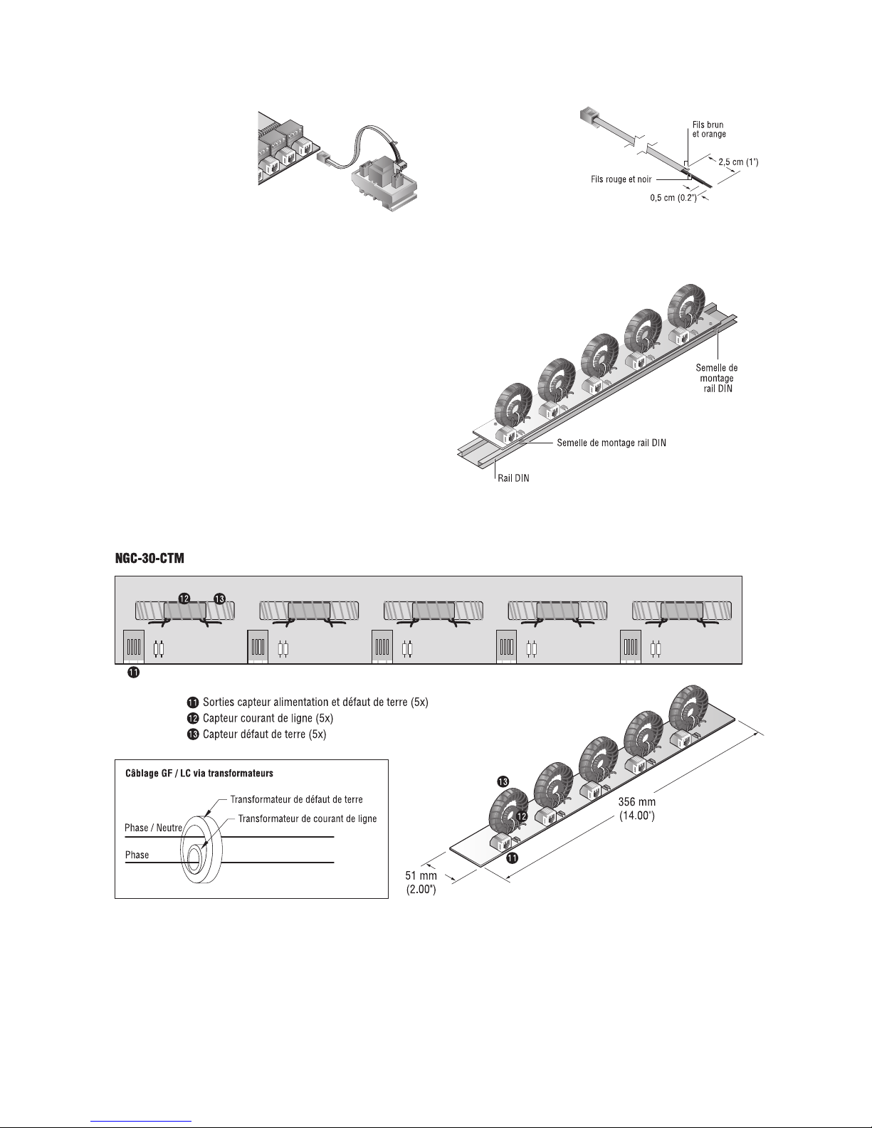
Montage du NGC-30-CTM
Chaque NGC-30-CTM se monte sur un rail DIN 35. Il doit
êtreinstallé entre le disjoncteur ou le bornier et le contacteur
ou le relais statique dans l’armoire électrique.
NOTICE D’INSTALLATION NGC-30-CTM
Capteur de tension – option
Le capteur de tension en
option surveille des tensions
de 80 à 290 V ca. Ce capteur
de tension se connecte
sur l’une des cinq entrées
courant de ligne/de terre
du NGC-30-CRM.
Remarque: En utilisant le
capteur de tension, vous
perdez la possibilité de
surveiller le défaut de terre
et l’alimentation du circuit
concerné.
Préparation du câble
Remarques:
1. Couper une extrémité
d’un câble de défaut de
terre/de ligne.
2. Dénuder l’isolant sur
environ 2,5 cm.
3. Dénuder l’isolant rouge et
noir sur environ 0,5 cm.
4. Connecter les fils rouge
et noir au bornier. La connexion
n’est pas sensible à la polarité.
5. Couper les fils brun et orange qui dépassent de l’extrémité.
nVent.com | 23
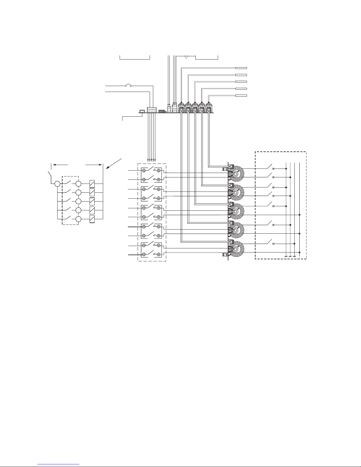
Tension ca jusqu’à 277 V ca
Vers boîte de raccordement
alimentation câble chauffant
Sortie relais alarme
Alimentation
contacteur
230 V ca
L
N
NGC-30-CRM
NGC-30-CTM
Tableau de distribution avec
disjoncteurs standards
RTD
Entrée 230 V ca
Écran
tactile
NGC-UIT
5
4
3
2
6
12
10
8
3
1
Contacts pour relais
230 V ca
L N
Relais
pilotes sur
circuit
imprimé
Bobines des
contacteurs
Vers bobines
des contacteurs
(voir détails)
N
ø1ø3ø
2
1
Alimentation
12 V cc
CONFIGURATION DU SYSTÈME NGC-30-CRM
24 | nVent.com
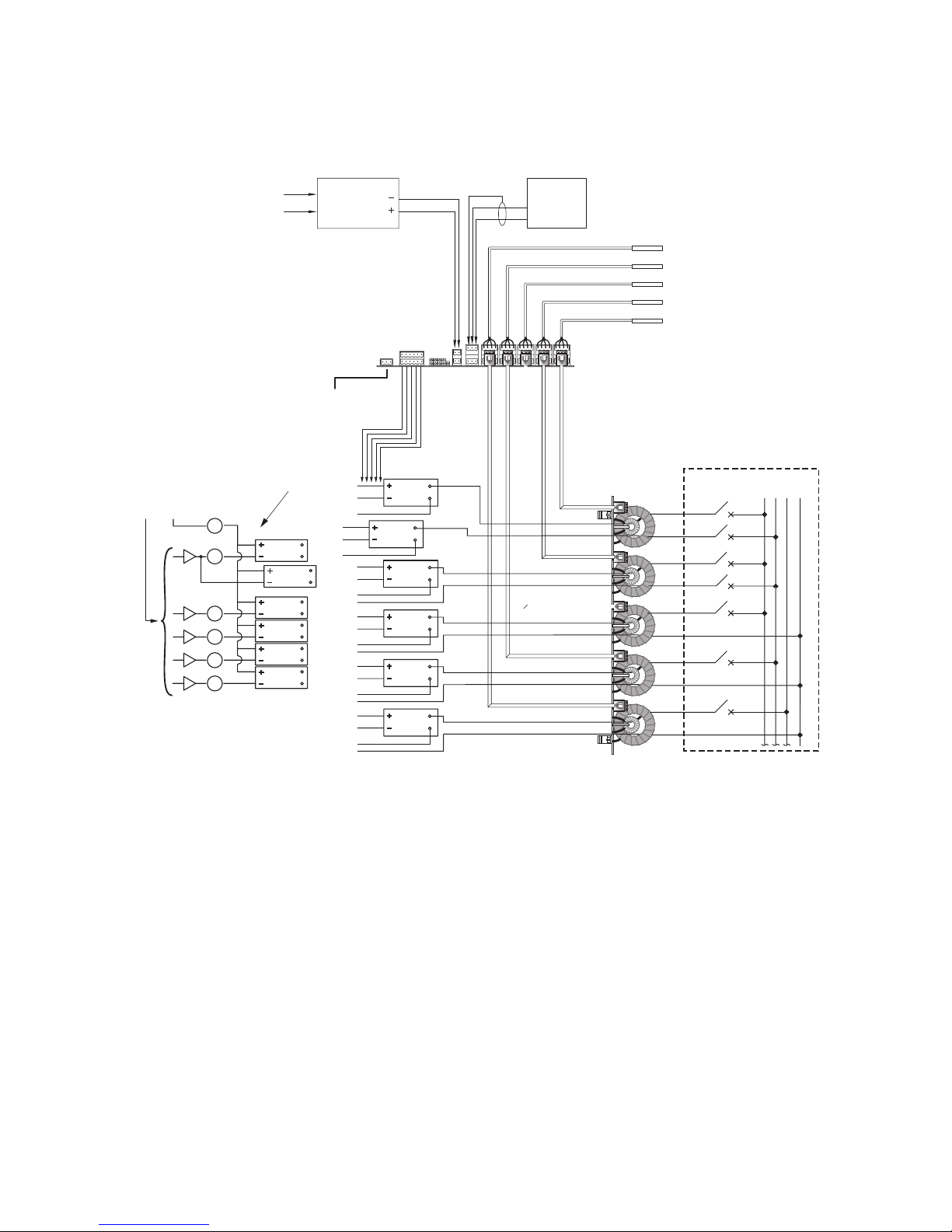
Remarque: Alimentation
12 V cc fournie par
le NGC-30-CRMS
Alimentation
12 V cc
NGC-30-CRMS
NGC-30-CTM
Tableau de distribution avec
disjoncteurs standards
Entrée 230 V ca
N
ø1ø3ø
2
SSR
SSR
SSR
SSR
SSR
SSR
SSR
SSR
SSR
SSR
SSR
Tension ca jusqu’à
277 V ca
Sortie relais alarme
Alimentation
interne SSR
12 V cc
6
5
12
10
8
3
1
4
3
2
1
Générateur sortie
Interne
12 Vdc
+–
SSR
Vers entrée
cc SSR
(voir détails)
Vers boîte de raccordement
alimentation câble chauffant
(typique 5)
Écran
tactile
NGC-UIT
RTD
CONFIGURATION DU SYSTÈME NGC-30-CRMS
nVent.com | 25
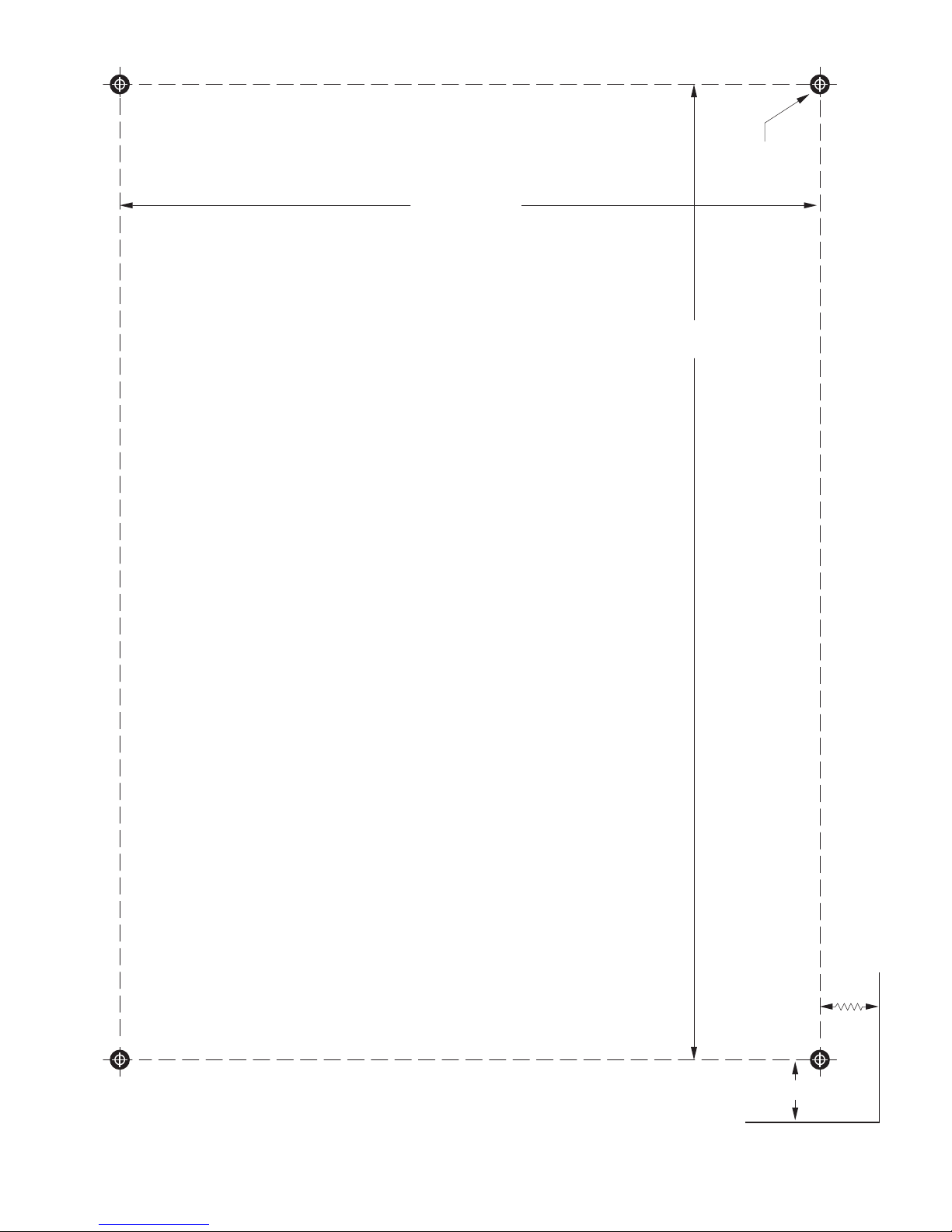
18 cm (7.00")
25 cm (9.75")
1,5 cm (0.625")
6,2 cm (2.4")
ø
0,5 cm
(0.188")
Haut du Card Rack
NGC-30 –CR. Gabarit de perçage pour montage mu
ral.
(Remarque:
vérifier que le gabarit est imprimé à la bonne échelle.)

26 | nVent.com
INSTRUCTIONS D’INSTALLATION –
GÉNÉRALITÉS
1. Les composants NGC-30 doivent être installés:
• Conformément aux normes en vigueur en matière
d’installations électriques et de sécurité
• In an enclosure suitable for the application environment.
When used in hazardous (Class I, Div. 2 or Zone 2) locations,
aminimum IP54 enclosure is required.
2. Les composants NGC-30 doivent être protégés par
desdispositifs externes de coupure et de protection contre
lessurtensions (disjoncteur, fusible, etc.).
L’équipement de déconnexion doit:
• déconnecter tous les conducteurs sous tension non
mis à la terre
• être situé à proximité de l’équipement
• être facilement accessible par l’opérateur
• être identifié comme équipement de déconnexion
de l’équipement
3. L’isolant du câblage d’alimentation doit être dimensionné
pourles tensions et températures maximales de l’application.
Les conducteurs doivent être dimensionnés pour l’application
et protégés par un dispositif externe de protection contre les
surtensions.
4. Certaines configurations utilisent plusieurs sources
d’alimentation. Elles doivent être mises hors tension avant
de procéder à toute intervention sur un circuit contrôlé par
lerégulateur.
5. La sécurité du matériel peut être compromise s’il est utilisé
au-delà de ses spécifications ou à des fins non conformes
à sa destination initiale.
6. S’assurer que l’emplacement choisi est compatible avec
laclassification pour laquelle le produit est agréé.
7. Manipuler les modules CRM(S) et CTM avec précautions lors
de leur installation, en évitant les chocs mécaniques.
8. Lors de l’installation des modules, porter un bracelet
antistatique relié à la terre pour éviter que des décharges
électrostatiques n'endommagent les composants.
ÉMISSIONS ELECTROMAGNÉTIQUES –
DÉCLARATION DE CONFORMITÉ
Cet équipement a été testé et jugé conforme aux exigences des
équipements numériques Classe A, conformément au chapitre 15
de la réglementation FCC. Ces limites sont conçues pour fournir
une protection raisonnable contre les interférences nocives dans
les installations résidentielles. Cet équipement génère, utilise
et peut émettre des ondes hertziennes et, lorsqu’il n’est pas
installé et utilisé conformément aux instructions, peut perturber
considérablement les communications radio.
Il n’existe toutefois aucune garantie qu’une installation soit
exempte d’interférences. Si l’équipement perturbe la réception
des ondes radio ou télévisuelles – ce qui se constate en éteignant
et rallumant l’équipement il incombe à l’utilisateur de tenter de
remédier à la situation comme suit:
– Réorienter ou déplacer l’antenne de réception.
– Augmenter la distance entre l’équipement et le récepteur.
– Brancher l’équipement sur une prise appartenant à un autre
circuit que celui auquel est raccordé le récepteur.
– Consulter le revendeur ou un technicien radio/TV
expérimenté.
Cet équipement numérique Classe A est conformé à la norme
canadienne ICES-003.

nVent.com | 27

©2018 nVent. All nVent marks and logos are owned or licensed by nVent Services GmbH or its affiliates. All other trademarks are the property of their respective owners.
nVent reserves the right to change specifications without notice.
Raychem-IM-INSTALL113-NGC30-ML-1805 PCN 1244-004933
Europe, Middle East, Africa(EMEA)
Tel +32.16.213.511
Fax +32.16.213.604
thermal.info@nvent.com
België/Belgique
Tel +32 16 21 35 02
Fax +32 16 21 36 04
salesbelux@nvent.com
Bulgaria
Tel +359 5686 6886
Fax +359 5686 6886
salesee@nvent.com
Česká Republica
Tel +420 602 232 969
czechinfo@nvent.com
Denmark
Tel +45 70 11 04 00
salesdk@nvent.com
Deutschland
Tel 0800 1818205
Fax 0800 1818204
salesde@nvent.com
España
Tel +34 911 59 30 60
Fax +34 900 98 32 64
ntm-sales-es@nvent.com
France
Tél 0800 906045
Fax 0800 906003
salesfr@nvent.com
Hrvatska
Tel +385 1 605 01 88
Fax +385 1 605 01 88
salesee@nvent.com
Italia
Tel +39 02 577 61 51
Fax +39 02 577 61 55 28
salesit@nvent.com
Lietuva/Latvija/Eesti
Tel +370 5 2136633
Fax +370 5 2330084
info.baltic@nvent.com
Magyarország
Tel +36 1 253 4617
Fax +36 1 253 7618
saleshu@nvent.com
Nederland
Tel 0800 0224978
Fax 0800 0224993
salesnl@nvent.com
Norge
Tel +47 66 81 79 90
salesno@nvent.com
Österreich
Tel +43 (2236) 860077
Fax +43 (2236) 860077-5
info-ntm-at@nvent.com
Polska
Tel +48 22 331 29 50
Fax +48 22 331 29 51
salespl@nvent.com
Republic of Kazakhstan
Tel +7 495 926 1885
Fax +7 495 926 18 86
saleskz@nvent.com
Россия
Тел +7 495 926 18 85
Факс +7 495 926 18 86
salesru@nvent.com
Serbia and Montenegro
Tel +381 230 401 770
Fax +381 230 401 770
salesee@nvent.com
Schweiz/Suisse
Tel 0800 551 308
Fax 0800 551 309
info-ntm-ch@nvent.com
Suomi
Puh 0800 11 67 99
salesfi@nvent.com
Sverige
Tel +46 31 335 58 00
salesse@nvent.com
Türkiye
Tel +90 560 977 6467
Fax +32 16 21 36 04
ntm-sales-tr@nvent.com
United Kingdom
Tel 0800 969 013
Fax 0800 968 624
salesthermalUK@nvent.com
nVent.com
 Loading...