

nvent Schroff RackChiller InRow, 60714-079, 60714-080, 60714-081, 60714-082 Maintenance Manual

RackChiller InRow
Chilled water cooled units
InstallatIon and maIntenance guIde
Issue 1.0.0
October 2018
nVent.com/SCHROFF | 1

InstallatIon and maIntenance guIde
This document
• Distributed copies will not be updated.
• It has been designed for viewing as a PDF le and double sided printing
(subject to copyright – see below) for a hard copy.
• Copies of this document can be obtained from nVent Schroff GmbH.
Copyright notice
The condential information contained in this document is provided solely for use by nVent employees and
system owners and is not to be released to, or produced for, anyone else.
Neither is it to be used for reproduction of this unit or any of its components.
All specications are nominal and subject to change without prior notice as design improvements occur.
Disclaimer
Schroff shall not be held liable for any errors that may be included in this documentation.
Liability for direct and indirect damage that occurs in connection with the supply or use of
this documentation is excluded to the extent permitted by law.
Schroff reserves the right to change this document, including the disclaimer of liability, at
any time and Schroff shall not be liable for the potential consequences of these changes.
Produced by
nVent
Schroff GmbH
Langenalber Str. 96 - 100
75334 Straubenhardt, Germany
The details in this manual have been carefully compiled and checked – supported by certied Quality
Management System to EN ISO 9001/2000.
The company cannot accept any liability for errors or misprints.
The company reserves the right to amendments of technical specications due to further development and
improvement of products.
Copyright © 2018 nVent.
All rights and technical modications reserved
nVent.com/SCHROFF | 2

InstallatIon and maIntenance guIde
Contents
Product information 6
RackChiller Models 6
Electrical ratings 6
Important safety information 7
Safety symbols 7
Safety instructions 8
Other important information 9
Rating label 9
Warranty 10
Installation 10
Pre-installation checks 10
In Row cooler installation 10
Installation guidelines 10
Options 11
Stages 11
Required parts 11
Required tools 11
Fitting an In Row cooler into a cabinet row 12
In Row cooler removal 12
Disconnecting hoses, removing and draining the coil 12
In Row maintenance 13
Fan replacement 13
Electrical installation 14
Fuse replacement 14
Central Management System (CMS) 15
Input side 15
Power side 15
Inside the CMS - circuit boards and jumper settings 15
CMS - power side basic wiring 16
CMS input side – basic wiring for water version 16
CMS picture front panel, wiring example – water version standard wiring 17
CMS picture front panel connections – Belimo EPIV valve 18
Emeter 3 wiring for single phase monitoring (CMS power side) 19
Central Management System (CMS) 21
CPCO commander 21
Communication 22
BMS port 22
CMS controller – connection and power-up 23
Connection 23
nVent.com/SCHROFF | 3

InstallatIon and maIntenance guIde
CMS controller – power-up, warning notice and alarm guide 24
Power up – Master Display 24
Warning notice 25
Alarm guide 25
CMS controller – Master display and software version 26
Master display 26
Software version 26
CMS controller buttons 27
CMS controller – navigating menus 28
Master display 28
Navigating the menus 28
CMS controller software overview 29
CMS controller – user access and password information 30
Access information 31
On/off screen 32
CMS controller – view status 33
Status/fans 33
Digital inputs 34
Digital outputs 35
Valve control status 35
Status IO screen 36
Status serial probes screen 36
Emeter 37
CMS set-up of water versions 38
Set-up/general 38
Overview of the different water models. 39
Fan control 1Z 39
Fan control 2Z 39
Fan control 3Z 39
System control 39
AV control 39
Set-up probes 40
Serial probes set-up 41
Set-up Belimo EPIV valve 42
Set-up of temperature control compensation 43
Set-up of probe alarm 43
Fan set-up 44
Set fan type and zones 45
Set digital outputs 45
nVent.com/SCHROFF | 4

InstallatIon and maIntenance guIde
Digital input set-up 46
Custom alarm set-up 47
Cold Aisle set-up 48
Leak alarm 48
Set-up of the valve feedback alarm 48
Air-on alarm 49
Set-up contact details 49
Probe calibration 49
Erase alarm log 50
Units of measurement 50
Fan delay 50
Energy meter 51
Thermistor functions 52
Fan control 53
Regulation/zone 1 53
Zone 2 control 54
Chiller regulation for zone 1, zone 2 and zone 3 control 56
Regulation/chiller, zone 1/2/3 mode 56
Chiller regulation for AV and system control 57
Control of fan alarm 58
Fan cut-off control 59
High low control temperature 60
Data logger 62
Preventative maintenance warnings 63
Text warnings/advisories 63
PM warnings – clean coil 63
Other PM warnings than can be set in a similar way are: 64
System checks 64
Alarm checks 65
Central Management System (CMS) 66
CMS controller – CMS display pairing 66
CMS circuit diagram 68
RackChiller Water software – CPCO mini inputs and outputs table 69
nVent.com/SCHROFF | 5

InstallatIon and maIntenance guIde
Product information
The RackChiller range of products provide cooling to rack mounted IT equipment in data centers.
They have been designed with energy efciency and high equipment density in mind.
They can replace the traditional approach to data center cooling or work alongside existing data center
designs as it is modular and scalable.
Designed to be connected to existing or new external cooling plant, RackChiller units are made up of a heat
exchanger, fans for airflow and a Centralised Management System (CMS) which oversees the control and
interfaces with BMS or other management systems.
The CMS lies at the heart of the RackChiller In Row solutions, keeping the room ambient temperature
controlled locally and at cabinet level. It automatically adjusts the fan speed, flow rate and, if necessary,
the output temperature resulting in a consistent delivery of cooled air into the data center with no operator
intervention. The whole process can also be overseen and controlled at individual cabinet level, room level
and remotely via any of the industry standard communication protocols. Water cooled variants of the In
Row system keep water above dew point which keeps the system free of condensation.
RackChiller Models
The following variants of the cooling modules are available:
- 60714-079 RackChiller In Row 2000mm height, 300mm width with 2x 230V Power Input
- 60714-080 RackChiller In Row 2000mm height, 600mm width with 2x 230V Power Input
- 60714-081 RackChiller In Row 2000mm height, 300mm width with 2x 208V Power Input
- 60714-082 RackChiller In Row 2000mm height, 600mm width with 2x 208V Power Input
Electrical ratings
NOTE: The CMS System is provided with a dual back-up supply facility in the event of a main supply failure.
Power will automatically change over to the alternative power input.
nVent.com/SCHROFF | 6

InstallatIon and maIntenance guIde
Other ratings
Fan Output (Output A) 200-240V, 50/60Hz, 10A Max
Auxiliary Output (Output B) 200-240V, 50/60Hz, 315mA
Water Cooled models
(coil dependant, nominal
MWP 6 bar, 20 to 83 l/m, 15 to 25 °C
values)
Weights Some models weigh in excess of 145kg (319.67 lbs)
Nominally less than 74 dB.
Sound levels
NOTE: Unit may run at 100% under fault condition which
will encroach on 85 dBa
Operating temperature 15 to 40°C
This product is to be connected to an appropriately rated branch circuit protected supply.
THIS PRODUCT MUST BE GROUNDED/EARTHED.
Supplied with 2 x SJT cables with C19 connectors, 3 x 16 AWG, 300V, 70°C, VW-1.
The units are provided with dual inputs. Ensure that both inputs have been isolated before
servicing.
This product must be installed in accordance with local electrical codes.
Important safety information
Safety symbols
Symbol Denition
Dangerous Voltage
Warning / Caution
Protective Earth
(Ground)
Heavy
To indicate hazards arising from dangerous
voltages.
An appropriate safety instruction should be
followed or caution to a potential hazard exists.
To identify any terminal which is intended
for connection to an external conductor for
protection against electric shock in case of
a fault, or the terminal of a protective earth
(ground) electrode.
This product is heavy and reference should be
made to the safety instructions for provisions
of lifting and moving.
nVent.com/SCHROFF | 7

InstallatIon and maIntenance guIde
Important safety information
Safety instructions
• The RackChiller Systems contains no user serviceable parts inside.
• The RackChiller system requires an external means of isolation for both the incoming power and
cooling supplies.
• Protect the power cord from being walked on or pinched, particularly at the hinge, plugs and outlets.
Should a power cord become damaged, isolate the system and remove from service until an
appropriate replacement can be sourced and tted.
• Do not block any ventilation openings.
• Refer all servicing to qualied personnel experienced with these types of installations.
• Should a fault occur with the product, immediately isolate and disconnect the incoming power.
• This unit has a dual supply – isolate both supplies before carrying out any work. Pull out both
cables to shut off. The end user is to be guided on other methods of isolation.
• Always ensure the machine is level when in use.
The units must be installed vertically on a level, dry floor.
• The machine should be used as provided and should not be tampered with or altered as the
machine contains inbuilt safety systems which could be compromised by any interference.
• This equipment is designed to be installed in an ofce or data center environment and is for indoor use only.
• The installation and operation should be conducted in accordance with local regulations and
accepted codes of good practice.
• Adequate ttings to be used – they must not be to the detriment of any UL or local standard.
• The appropriate Personal Protection Equipment (PPE) should be worn at all times.
Fuses
Fuse ratings table
CMS model F1 F2 F3 F4 F5 F6 F7 F8 F9 Power
board
-
-
-
Taco
board
(230V)
60714-080
60714-079 and
F0.5AH250V
T12.5AH250V-T12.5AH250V
T0.315A250V
T10AH250V
T0.315AH250V
T2AH250V
(208V)
60714-082
60714-081 and
F0.5AH250V
T12.5AH250V
T12.5AH250V
T12.5AH250V
T12.5AH250V
T0.315A250V
T0.315A250V
T10AH250V
T10AH250V
T0.315AH250V
T2AH250V
For systems that are powered phase to phase (208V), always replace both supply fuses when one has failed.
nVent.com/SCHROFF | 8

InstallatIon and maIntenance guIde
Other important information
Some parts are sensitive to electrostatic discharge.
Observe all ESD precautions.
Failure to do so can result in damage to the equipment.
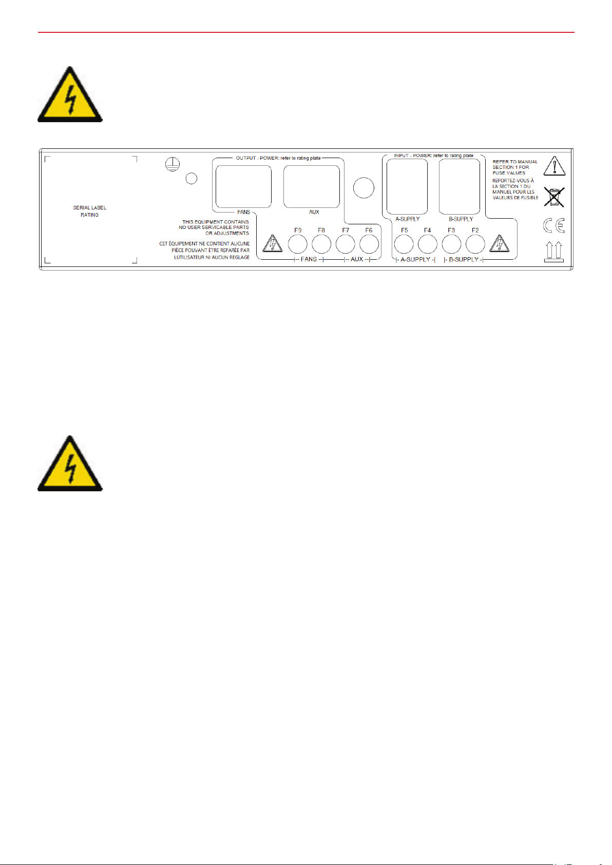
Rating label
Each unit has a rating label afxed to the top of the RackChiller management system unit containing the
following information:
Warranty
Failure to comply with the manufacturer’s installation instructions could affect the reliability and
performance of the unit and invalidate the warranty.
Warranty is also subject to the implementation of a planned service / maintenance agreement as stipulated
in the warranty booklet supplied with the unit and/or the sales contract.
Please read the user’s guide
The In Row units are carefully engineered to provide energy efcient cooling direct at rack level, ensuring
control of room ambient temperature.
This guide helps the set-up, operation, monitoring and maintenance of the RackChiller system via the
Central Management System (CMS) unit and its controller.
nVent.com/SCHROFF | 9

InstallatIon and maIntenance guIde
Installation
Pre-installation checks
• The water version of the In Row cooler is supplied with the appropriate hoses from the factory.
• Make local arrangements for isolation of the power supply.
• Ensure that the water supply pressure doesn’t exceed the unit rating.
• The unit is supplied with 2 x SJT cables with C19 connectors, 3 x 16 AWG, 300V, 70°C, VW-1.
• Ensure that the unit is not connected to any electrical supply.
• Check for transport damage and report any to your supplier.
• Remove any packaging material.
• Ensure that the floor is able to take the weight of the unit.
In Row cooler installation
It is important to prepare the area before installing the In Row cooler and follow all safety guidelines.
Installation guidelines
• Please read all safety instructions before continuing.
• Please read through this document before commencing installation.
• Do not obstruct air paths to the inlet or outlet of the In Row cooler.
• Water supply, rated 3 bar (45 psi).
• Adequate ttings should be used – they must not be to the detriment of any UL or local standard.
nVent.com/SCHROFF | 10

InstallatIon and maIntenance guIde
In Row cooler installation
Options
1. The In Row cooler is available as a 300mm wide or 600mm wide cabinet.
2. It is designed to be installed within a row of cabinets, either as an open row
or as part of a contained hot or cold aisle.
Stages
1. Preparing the working area.
2. Connecting hoses to the cooler
3. Installing the cabinet.
4. Filling the cooling system.
5. Setting up and operating the CMS controller.
Required parts
1. This documentation.
2. In Row cooler.
3. Cabinets, end of aisle doors, roof (Options).
4. RackChiller attachment hoses.
5. RackChiller commissioning valves and flow control valves.
6. CMS connector kit.
Required tools
1. Pozidrive screwdrivers #2 and #3.
2. Flat blade screwdriver.
3. Electrician’s screwdriver.
4. Retractable blade.
5. 10mm AF spanner.
6. 8” wide jaw adjustable spanner.
nVent.com/SCHROFF | 11

InstallatIon and maIntenance guIde
In Row cooler installation
Fitting an In Row cooler into a cabinet row
1. Move the In Row cooler into approximately the correct position against the adjoining cabinet.
2. Remove any protective packaging.
3. Remove the transit castors.
NOTE: Refer to the important safety information on pages 6-9 of this document.
4. Move the In Row cooler into its nal position against the cabinet.
5. Position next to the cabinet and bay to the In Row cooler.To bay the cooler next to a nVent cabinet use
20714-001 for Varistar and 20714-002 for a Proline cabinet. Follow the instructions provided with the
baying kit.
7. Pass the hoses through the bottom or top of the In Row cooler, as required and connect to pipework.
8. Feed the power leads into the In Row cooler from above or below, as required and connect.
9. Power up the In Row cooler and check operation.
In Row cooler removal
Disconnecting hoses, removing and draining the coil
Both the coil header (circuit injections) and hose connections are at the top of the coil.
A drain point at the lowest point of the coil would not drain the coolant.
The recommended method for safe, dry removal of the In Row cooler within a working Data Center is as
follows:
1. Shut off the coolant supply pipe wait 10 seconds then shut off the supply pipe.
2. Place a suitable container below the hose to be removed.
3. Put the spanners onto the hose and cover with a piece of rag to avoid any spray.
4. Loosen the hose and allow any pressure to dissipate.
5. Slowly unscrew the hose catching the coolant in the container. Expect 2.5 - 3l of coolant to be discharged.
6. Loosen the second hose. Additional coolant will siphon through the rst hose. Disconnect the second hose.
7. Cap both hoses, feed back into the In Row cooler and cable tie to the frame as high up as possible.
8. Disconnect the cabling connections.
9. Remove the baying bolts from the adjoining cabinets.
10. Remove any xings attaching the aisle roof to the In Row cooler.
11. Move the In Row cooler out of the aisle and t transit castors (optional).
12. Take the In Row cooler out of the Data Center.
13. Once in a suitable location (outside) the side panel can be removed and the coil removed from the In Row cooler.
14. Lay the coil down and remove the hose caps. The remaining coolant can be allowed to drain.
The coil may need to be turned upside down to effect full draining of the coil loops.
15. If the coolant contains any additive(s) dispose of the coolant in accordance
with the relevant Safety Data Sheet(s) & local waste disposal codes.
nVent.com/SCHROFF | 12
InstallatIon and maIntenance guIde
In Row maintenance
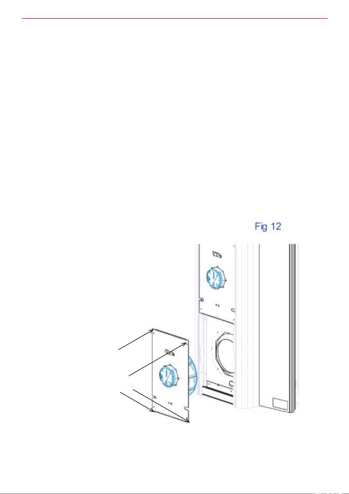
Fan replacement
1. Identify the failed fan from the alarm log.
2. Isolate the Electrical supply(s).
3. Remove the black powdered column, see g. 12 for 600mm wide device.
4. Disconnect the two connectors on the faulty fan.
NOTE: The connectors have retention clips.
5. Once rotation has stopped, unscrew the three screws holding the fan panel to the perforated shelf.
6. Remove the four retaining screws in the corners of the fan panel.
7. Withdraw the fan panel and slide the cable loom from the panel.
8. Replace it with the new fan assembly panel and bolt it back in place.
9. Spin the new fan to ensure correct alignment with inlet ring and, if necessary, adjust the panel.
10. Reconnect the two molex connectors.
11. Reinstate the electrical power supply(s) to the CMS.
NOTE: The fan will immediately ramp up to the current fan speed.
12.After a short while, the fans will resume cooling at the rate determined by the temperature sensor.
13. Ret the steel column.
14. Reset the alarm.
Remove 4 x retaining screw
– keep them safe.
Fit grommet, which is captive on the
door loom to fan panel, on either left or
right hand side of the panel
nVent.com/SCHROFF | 13
InstallatIon and maIntenance guIde
Electrical installation
The unit will be with a pair of C19 to C20 cable (dual supply systems).
Plug the C19 cordset provided into the A-Supply socket of the CMS.
Additionally, plug a further C19 cordset into the B-Supply socket for the dual supply back-up option.
Provisions must be made to isolate both supplies for maintenance or in the event of a hazard.
Fuse replacement
Refer to the important safety information on pages 6-9.
In the unlikely event that a fuse requires to be replaced the following instructions should be adhered to.
1. Isolate electrical power.
NOTE: Both supplies must be disconnected where a dual supply is provided.
2. Identify, remove and discard the offending fuse.
3. Replace the offending (5x20mm) fuse with an approved rated fuse as detailed in the table on page 7.
4. Reinstate the incoming power supply(s).
nVent.com/SCHROFF | 14

InstallatIon and maIntenance guIde
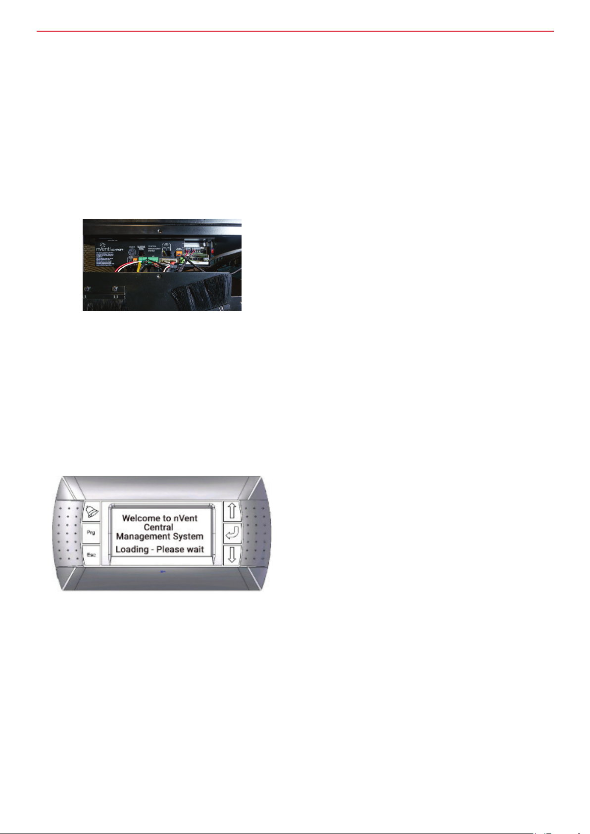
Central Management System (CMS)
Input side
Power side
Inside the CMS - circuit boards and jumper settings
Power board (230V version shown)
CPCO mini
Transformer
Taco board
When a 6 fan
system is used
set this jumper to
FAN6, otherwise
set to NTC0
MS – Enables or disables
the backup circuit. This
forces the fans (Y1) to run
at full speed. The valve
(Y2) will remain at its last
position if there is a failure
in the control system
(CPCO mini).
DL – Delays the backup
circuit for Y1 & Y2 for 30
seconds whilst the control
system boots up. It should
be used when the software
delay for fan startup has
been set (see fan delay in
set-up section).
Y3 – Has the same
function as DL but works
for control output Y3 and
should be set to ON when
3 zone fan control and
software delay for fan
startup are both enabled.
For use with valve
feedback set to off.
nVent.com/SCHROFF | 15

InstallatIon and maIntenance guIde
CMS - power side basic wiring
Valve control fuse,
Fan signal output, valve
signal output and valve
feedback
Valve power
24V AC
connection, 24V AC G
= +ve pin
Front LED
indicator
connection
Door loom
connection
Temperature sensor
connections
Custom alarm/cold
aisle/Leak alarm output
Digital input 2
connection:
Custom alarm/cold
aisle/Leak alarm
output
Dead unit/
power failure
(NO3)
TCP/IP connection (high
end versions CPCO only)
Global alarm
output (NO2)
Field bus
connection
CMS input side – basic wiring for water version
Earthing point
Fan power
output
E-meter power
output
Refer to fuse
table for fuse
information.
E-meter sensing
loop
Power input A
Power input B
nVent.com/SCHROFF | 16

InstallatIon and maIntenance guIde
CMS picture front panel, wiring example - water version standard wiring
Fan loom
**Optional thermistor, not used where 6 fans are present.
The following features will require a serial probe to be
set-up as cabinet front/room temperature:
Temperature control comp. (See serial probe set-up
section)
Probe alarm (See serial probe set-up section)
Fan cut-off (see control section)
***AV control, In system control NTC2 measures return
water temperature
NTC0, Cabinet front/Room**
wire these thermistors to NTC GND using the white wire
NTC3, Temp zone 3/Spare
NTC2, Air-on coil***
NTC1, Air off coil
CMS picture front panel, wiring example– Belimo valve for water version
*Orange wire is only required when
valve feedback has been enabled.
Red (1)
Black (2)
White (3)
Orange (5)*
Belimo actuator
with water valve
nVent.com/SCHROFF | 17
InstallatIon and maIntenance guIde
CMS picture front panel connections – Belimo EPIV valve
Shielding
shielding
Red (1)
Black (2)
Grey (7)
Pink (6)
Belimo EPIV
actuator and valve
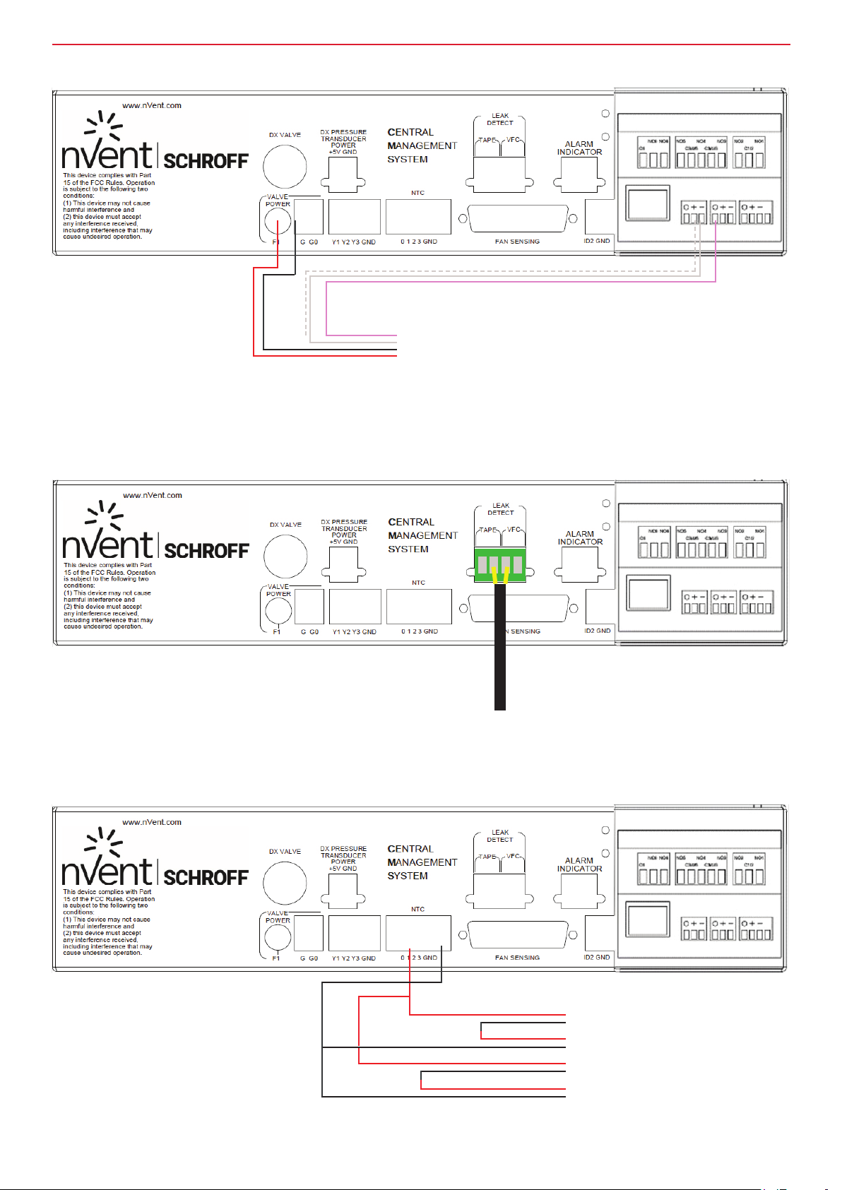
CMS picture front panel connections – leak detection option
Connect leak tape phoenix
connector to here
Multiple thermistor wiring
Optional VFC contact output to BMS.
Closed when leak has been detected.
In some cases it may be desirable to wire multiple thermistors into a single NTC. For example, you may
wish to see the average temperature on the inside of a rack, rather than use a single thermistor to measure a single point.
In this case, four thermistors wired in series-parallel must be used.
NTC1, Air-off coil
NTC1, Air-off coil
NTC1, Air-off coil
NTC1, Air-off coil
nVent.com/SCHROFF | 18

InstallatIon and maIntenance guIde
Emeter 3 wiring for single phase monitoring (CMS power side)
Power wiring to Emeter 3, CMS-0006-XX
Current sensing loop
CMS-0007-XX
Current transformer (CT)
Emeter 3 wiring for single phase monitoring (input side)
Wire the emeter into the eld bus.
Wires must be shielded.
Use a Belden 9841 cable.
Connect S1 on CT to ‘1’on the emeter, and S2 to ‘2.’
nVent.com/SCHROFF | 19

InstallatIon and maIntenance guIde
LED Indicator
The LED indicator is red when the unit
is in alarm, and show is green when
the system is running normally. It
plugs into the ALARM INDICATOR on
the CMS box.
nVent.com/SCHROFF | 20
InstallatIon and maIntenance guIde
Central Management System (CMS)
CPCO commander
The CMS controller will be set-up and installed in the unit in the factory.
The relevant CPCO mini commander unit connections for installation are shown below.
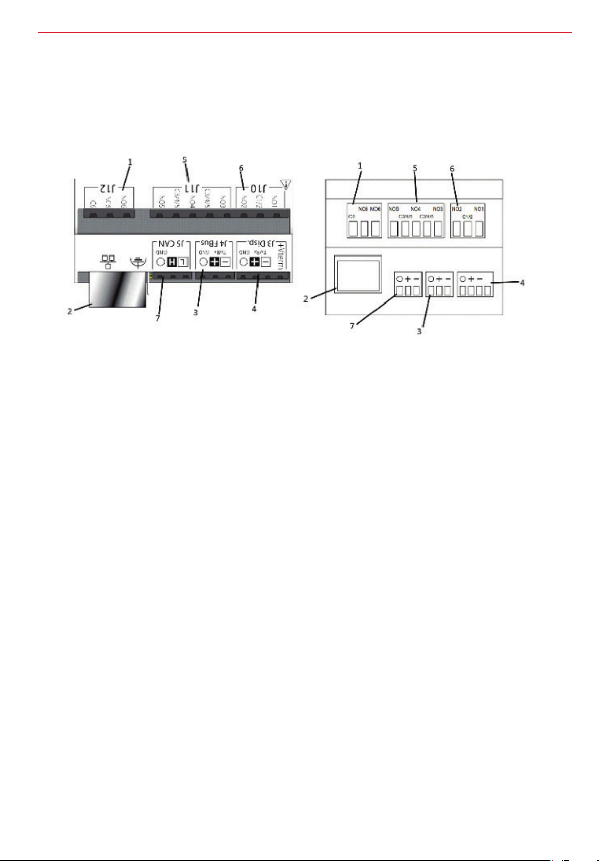
CMS unit rear panel connections – CPCO mini.
Top view of front face Side view of front face
1. J12 connection is for LED/Alarm. It connects to the alarm indicator on the CMS.
2. Ethernet connection (High end version only).
This is a modbus BMS connection in the Enhanced version.
3. J4 Fieldbus connection.
4. J3 CMS tool connection.
Actual connection from commissioning tool will be via an additional cable connected to J3.
It is on the lid of the CMS.
5. J11 connection
a. NO5 to C3/4/5 – connection for custom alarm / cold aisle and other ID2 related functions.
(See set-up section).
b. NO4 to C3/C4/C5 – connection for chiller call output / custom alarm.
c. NO3 to C3/C4/C5 – unit failure output. This output is closed when the CPCO unit is running.
6. J10 connection
a. NO1 to C1/2 – connection for power failure.
This output is closed when the unit has changed to the B power supply (usually UPS).
b. NO2 to C1/2 – Global alarm connection output.
7. J5 CANbus connection – High end versions only. This is not used.
nVent.com/SCHROFF | 21

InstallatIon and maIntenance guIde
Central Management System (CMS)
Communication
Previous versions of the CMS commander (PCO5) used a communication card for interfacing with a BMS system.
This is no longer required but there are different CPCO CMS versions depending on the type of interface required.
The High End version with Ethernet port The Enhanced version with BMS port
The Enhanced versions are daisy chained using Belden 9841 cable at the J6 BMS port.
Terminate the end furthest from the RMS using a 120 Ohm resistor between pins ‘+’ and ‘–’.
Connect the shielding to ground.
The High End versions are connected back to a hub using Cat 5 network cable with RJ45 connectors.
Consult the separate CPCO user manual for set-up details.
nVent.com/SCHROFF | 22
InstallatIon and maIntenance guIde
Central Management System (CMS)
CMS controller – connection and power-up
Connection
It is not necessary to switch off the CMS before connecting the controller.
Once connected, the controller will pair with the CMS and display the welcome screen as shown below.
To enable set-up and commissioning each CMS unit needs to be connected to a controller via an RJ11
lead. The RJ11 socket is located on the rear right-hand side of the CMS unit.
If the controller/commissioning tool is blank when connected or isn’t paired, refer to the CMS display pairing section.
Connection from the CMS controller to the
commissioning tool is via an RJ11 connector
which plugs into the back of the commissioning
tool and CMS controller.
Commissioning tool
WELCOME SCREEN IMAGE
Power up – initial screen
1. Do not press any buttons during the
CMS boot sequence.
2. The complete CMS boot sequence
takes approximately one minute.
3. The initial screen will be blank
followed by a message similar to the
one shown left. Once loaded, the display
will normally switch to one of the three
screens shown overleaf depending on
which of the three ‘Models’ / programs the
system was set-up with.
nVent.com/SCHROFF | 23

InstallatIon and maIntenance guIde
Central Management System (CMS)
CMS controller – power-up, warning notice and alarm guide
Power up – Master Display
1. Once powered up, the display will normally be one of the screens shown here depending on which of the
Models / programs was used in commissioning the CMS.
Typical screen when system is set to:
1. AV control (water versions)
2. SYSTEM control (water versions)
3. Single zone fan control (water versions)
4. Two zone fan control (water versions)
5. Three zone fan control (water versions)
nVent.com/SCHROFF | 24

InstallatIon and maIntenance guIde
Warning notice
If you nd that pressing Prg or the return key brings up this message (above), follow the User access instructions.
Alarm guide
If an alarm sounds, press the flashing red bell.
This will switch the display to the alarm guide.
To determine the cause of the alarm, use the cursor keys – then rectify the cause of the alarm.
Press Esc twice to revert to the master display.
NOTE: The display may vary depending on factory settings.
nVent.com/SCHROFF | 25
InstallatIon and maIntenance guIde
Central Management System (CMS)
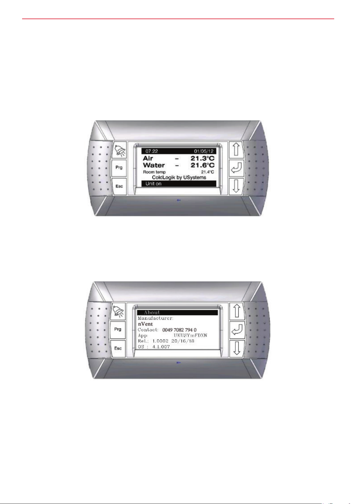
CMS controller – Master display and software version
Master display
1. The master display shown in the example below is that for the ‘System control’ model.
2. Temperatures shown should reflect the temperature at the sensors.
3. The date and time may need setting – refer to the Date / Time section for details.
4. Set-up / commissioning may be completed successfully without clearing faults.
NOTE: The display may vary depending on factory settings.
Software version
1. To display the software version: from the master display screen above, press either of the cursor
keys (the up or down arrow keys).
2. Press Esc to revert to the master display – although it will do so automatically after some time.
nVent.com/SCHROFF | 26

InstallatIon and maIntenance guIde
Central Management System (CMS)
CMS controller buttons
1. Alarm button.
Will show any active alarms.
Use the up / down cursor keys to scroll through the list and Esc to return to the menu or master display.
2. Program button.
Press to access set-up menus and then to move to the next menu selection.
3. Press to cancel the current selection and go back a menu level.
4. Up/down (‘cursor’) arrows.
Moves cursor up or down for menu selection, moves cursor left or right for menu selection.
Increases/decreases values when setting parameters.
5. Enter / return button.
Used to access menu selection / move to the next selection / accept entered parameter.
nVent.com/SCHROFF | 27

InstallatIon and maIntenance guIde
Central Management System (CMS)
CMS controller – navigating menus
Master display
From the master display, use Prg to access the main menu below.
This is the Menu screen, to navigate to one of the options use the Prg or cursor keys to highlight an icon.
The bar at the top of the screen shows the menu name.
Press enter / return to go to the menu.
Navigating the menus
The alternating flashing underscore (top left of the screen) indicates that the menu is ‘live’.
For menus with several pages, use the cursor keys to toggle to the next display.
Press enter / return to access the second tier menus and the cursor keys to alter the information.
Press enter / return to accept.
Prg can be used to return to the main menu.
Pressing Esc will take you back up a level in the menus.
nVent.com/SCHROFF | 28
InstallatIon and maIntenance guIde
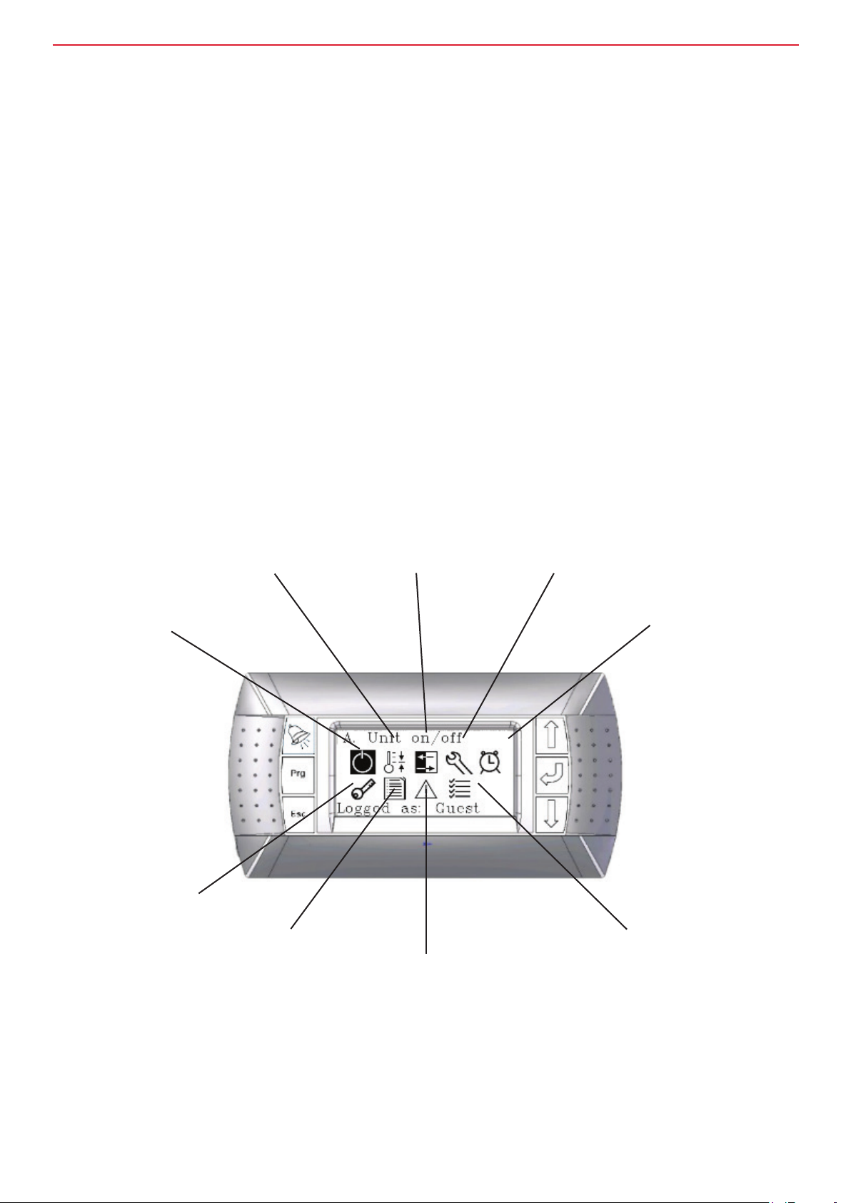
CMS controller software overview
A. On/Off - The systems can be turned off here. Generally the system will always try to run.
B. Control – Use to adjust set-points for fan control, valve control and other control related features.
C. Status - This shows the system running information. For example, fan speed / cabinet temperatures / valve opening etc. It is accessible by all users.
D. Setting - Mostly used for system commissioning. You can set device addresses, system
type, set-up the inputs and outputs etc. It is not normally used once commissioning has been
completed.
E. Date / time setting.
F. User access – used to change user access level. It is normally for service engineers to adjust
settings.
G. Set-up of periodic system tests and checks, and also to set maintenance reminders.
H. Data logger – Record of alarms.
I. Test mode – Factory use only. This is for testing the CMS before it leaves the factory.
A. On/off
B. Control
C. Status
D. Set-up
E. Date/time
F. User access
H. Data logger
G. Preventative maintenance
I. Test mode
nVent.com/SCHROFF | 29

InstallatIon and maIntenance guIde
Central Management System (CMS)
CMS controller – user access and password information
User access
To access the user access menu from the master display press the ‘Prg’ button and then press the up or
down cursor until the key icon has been highlighted.
Then press enter.
All other menus can be accessed in a similar manner.
Press return to highlight user name then use the cursor keys to choose Guest, End-User or Commission.
Test mode is for factory use only. Press return to accept – the highlighted section highlight switches to ‘Password’.
Use the cursor keys to input the password number; press return to move to the next number in the sequence.
nVent.com/SCHROFF | 30

InstallatIon and maIntenance guIde
Access information
COMMISSIONING
Available by password only
Consult supplier for
password
Menu item
GUEST
No password required
Default access level
On / off N / A Available
Control N / A Available
Status Available Available
Set-up N / A Available
Date / time N / A Available
User access Available Available
Alarm log Available Available
Preventative maintenance N / A Available
Test mode N / A N / A
nVent.com/SCHROFF | 31

InstallatIon and maIntenance guIde
Central Management System (CMS)
CMS controller – turning the unit on and off
On / off screen
To access the on/off screen from the master display press the ‘Prg’ button and then press the up or down
cursor until the key icon has been highlighted.
Then press enter.
Use either of the cursor keys (up/down) to turn the unit on or off.
NOTE: Fans will stop rotating when ‘off’ is selected; alarms may sound as system boots up.
When unit is turned on, the fans might not run.
Other parameters may need setting – such as cut off enabled – or there may not be a temperature demand.
nVent.com/SCHROFF | 32

InstallatIon and maIntenance guIde
Central Management System (CMS)
CMS controller – view status
This is a report function – you cannot rectify or change anything from these screens.
Use the cursor keys to view the different status reports.
What can be viewed in the status screen changes depending on the system type, but it is available in both
Guest and Commission user access levels.
Status screen
Status / fans
All models types and variants will have a fan status screen
The left hand column displays the command to the fans (as a % of full speed) from either Y1
(Zone 1, AV or System control fans), Y2 (Zone 3 fans) or Y3 (Zone 2 fans) on the CMS box.
2. The center column displays the rotational speed feedback from the individual fans.
3. The right hand column displays the expected feedback derived from an internal look-up table for the fans.
This is where an indication will be gained to set the fan fail differential in the general menu to avoid unwanted alarms.
nVent.com/SCHROFF | 33

InstallatIon and maIntenance guIde
Digital inputs
All models types and variants will have a digital input screen
Power supply displays the status of the PSU in use (option on dual PSU versions).
A is the normal operating status.
B shows that the rst power supply has failed and that the system is now running on the second power supply.
An alarm will be activated in this case.
The second line shows the status of digital input (DIN) 02.
The descriptive text will change depending on the mode selected.
Please refer to set-up section for digital input (DIN02) set-up.
nVent.com/SCHROFF | 34

InstallatIon and maIntenance guIde
Digital outputs
All models types and variants will have a digital output screen. The actual screen may vary between
models.
1. Power fail is the digital output that is activated when power supply A has failed in dual power supply versions.
It is a normally open contact, NO1 on the CPCO command unit.
2. Global alarm (NO2) is activated when any alarm is activated.
3. Dead unit is closed whilst the unit is operating and functioning correctly.
4. Chill change is a call (when closed) for a reduced water temperature when certain thresholds have been
exceeded (see control section).
It is also the condenser on/off signal (closed/open respectively) in the DX versions.
5. This is only available when DIN02 has been set to perform a function – see the set-up chapter.
6. Is open when the unit in not in an alarm state. It drives and output to and LED which changes from blue
to red when an alarm state has occurred, or when the unit has been set to ‘Off.’
Valve control status
This screen is available in water versions with a water valve only.
Real valve SP is the target set-point for the valve which is set in the control section. Valve command is how
open the valve is.
100% means that the valve is fully open.
The EPIV valve version of this screen shows valve command, feedback and flowrate.
nVent.com/SCHROFF | 35

InstallatIon and maIntenance guIde
Status IO screen
All models types and variants will have a digital output screen. The actual screen may vary between
models.
In single zone control this shows the temperature of the rst zone along with the fan command in % to fan zone 1.
This example also shows whether the chiller has been called to drop the water temperature (note ‘Chill
change’ on digital outputs status screen).
Other water versions may additional show the status of the valve (temperature and %age opening).
The EPIV valve version of this screen shows valve command, feedback and flowrate.
Status serial probes screen
All models types and variants will have a serial probe screen when serial probes are enabled.
Up to 7 serial probes are available (see set-up).
They can either be temperature sensors or combined temperature and humidity sensors.
nVent.com/SCHROFF | 36

InstallatIon and maIntenance guIde
Emeter
The Emeter is a device which show electric consumption of the CMS and cooling unit.
When the Emeter is enabled (see set-up) the following status screens become available which show
various information fed from the Emeter.
The Emeter is connected via modbus eldbus and can also be used to send data to the remote monitoring
system (not covered in this manual).
nVent.com/SCHROFF | 37

InstallatIon and maIntenance guIde
Central Management System (CMS)
CMS set-up of water versions
Set-up / general
To access the set-up menu press Prg to access the main menu screen.
Then use the cursor keys to highlight the set-up icon. The bar at the top indicates the chosen menu.
Then press enter / return.
Force unit on setting forces the unit to ON automatically when the system boots.
When set to ‘no’ the unit will be off after booting.
The model setting has 5 settings:
AV control / Systems control / Fan control 1Z / Fan control 2Z / Fan control 3Z.
See the next page for an explanation of the different models.
The valve can be set to EPIV or none. Only set to EPIV when a Belimo EPIV valve has been tted.
Settings for other valve types are available in other menus (see further below).
If an energy meter is tted it can be enabled here using En EM3se.
nVent.com/SCHROFF | 38

InstallatIon and maIntenance guIde
Overview of the different water models.
See control section for more detailed information.
Fan control 1Z
For systems that have no water valve or are air cooled only, then single zone fan control can be used.
The control thermistors for the fans will be connected to NTC 1 and all fans connected to Y1.
Fan control 2Z
This setting is also for systems that have no water valve or are air cooled only. Zone 1 fans must be
connected to Y1 on the CMS and Zone 2 fans must be connected to Y3.
Zone 1 fans will be controlled by the NTC1 thermistors and zone 2 will be controlled by the NTC2 thermistors.
On the main TACO board inside the CMS, the Y3 jumper must be set to Y3.
This jumper is located below the alarm indicator socket inside the CMS.
Fan control 3Z
This setting is also for systems that have no water valve or are air cooled only.
Zone 1 fans must be connected to Y1 on the CMS, Zone 2 fans must be connected to Y3 and Zone 3 fans
must be connected to Y2. Zone 1 fans will be controlled by the NTC1 thermistors, zone 2 will be controlled
by the NTC2 thermistors and zone 3 fans will be controlled by the NTC3 thermistors.
On the main TACO board inside the CMS, the Y3 jumper must be set to Y3 (see picture above).
System control
With system control, all the fan command wires are wired into Y1.
The fans are then controlled by NTC1, which is the off coil thermistor.
The valve is controlled by NTC2. NTC2 in this case would normally be attached to the return water pipe.
The valve command is wired into Y2 and the valve feedback (if required) is wired into Y3.
AV control
With this control method, the fans are controlled by the on-coil thermistor (NTC2) and the valve is
controlled by the off coil thermistor (NTC1).
The fan command for all the fans are wired into Y1, and the valve command is wired into Y2.
The valve feedback (if required) is wired into Y3.
nVent.com/SCHROFF | 39

InstallatIon and maIntenance guIde
Set-up probes
If any serial probes are to be used, the number can be set here. (up to 7).
NTC0 is only available when there are less than 6 fans.
It must be set to 0-10V fan where 6 fans are used. It may be set to None when it is not required.
The temperature at the front of the cabinet is usually monitored by NTC0. Where NTC0 is not available
(usually due to having a 6 fan system), the cabinet front temperature can be monitored via a serial probe.
Valve feedback (using Y3 as an input) can enabled or disabled.
Disable this if your valve has no feedback, or when you are using Y3 as a fan output for zone 3.
NTC3 as of writing performs no control function unless the system is in 3 zone control.
However, the text can be changed and the thermistor used for monitoring purposes.
nVent.com/SCHROFF | 40
InstallatIon and maIntenance guIde
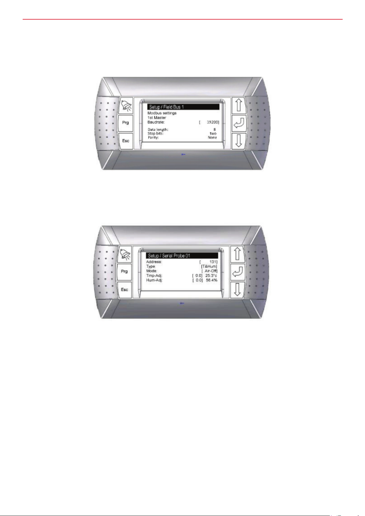
Serial probes set-up
If you have selected any number of serial probes as additional temperature sensors or humidity sensors
the following screen will be available and each serial probe will require setting up.
Please refer to the CPCO manual for eld bus wiring.
The only setting to change on the eld bus is the baud rate to 19200.
Ensure that the serial probes have been set so that the data length, stops bits and parity match the settings
shown on the screen.
The serial probe addresses start at 128 (address 00). Address 128 would mean that none of the serial
probes dip switches are set.
The next address is 131 and requires the serial address to be set to 01 via dip switches on the serial device itself.
132 is serial device address 02 etc…
You can set the type, mode (sensor location/control mode), and offset (calibration) adjustment.
The real time values of the sensors are shown.
If you have enabled 7 serial probes in the set-up/probes screen, you will have 7 probes to set-up.
nVent.com/SCHROFF | 41

InstallatIon and maIntenance guIde
Set-up Belimo EPIV valve
If you have enabled the EPIV valve on the set-up/general screen you will also have the Belimo EPIV valve to set-up.
The default address is 2.
The Belimo EPIV valve must be set to the same address.
The other menu items are not changeable.
nVent.com/SCHROFF | 42
InstallatIon and maIntenance guIde
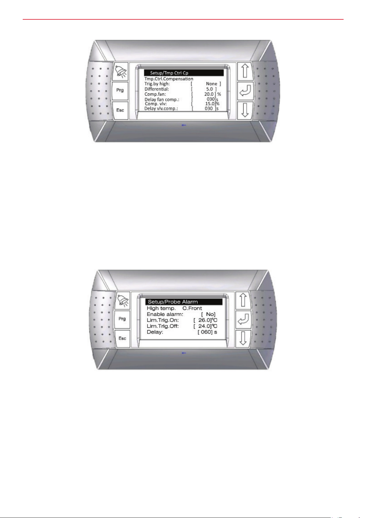
Set-up of temperature control compensation
This control is used to raise the fan speed and open the water valve by a xed percentage when the
temperature has risen above the set-point by the differential.
The trig by high setting can be changed from ‘None’ (which prevents this feature working) to ‘In Aisle’,
‘Cabinet Front or room’ which is a reference to the thermistor/serial probe which will be used to trigger the control.
The set-point reference is the air-off temperature (i.e. Valve set-point in AV mode).
For example, if the Trig.by high setting is set to C.Front (thermistor or serial probe at the front of the cabinet)
and the other settings on the screen above stay the same, when the cabinet front temperature is 5 degrees
above the air-off set-point (valve set-point in AV mode), then after 30 seconds the fan speed will increase
by 20% and valve opening will increase by 15%.
Set-up of probe alarm
When this alarm is active, the fans ramp up to maximum speed and the valve opens fully.
The CMS checks the cabinet front temperature and the alarm is active when the Lim.Trig.On set-point has
been exceeded for the delay time period.
It doesn’t turn off again until the temperature has dropped to Lim.Trig.Off set-point.
nVent.com/SCHROFF | 43

InstallatIon and maIntenance guIde
Fan set-up
This is for enabling or disabling the fan feedback.For 5 fan systems, Fan 6 will be set to ‘No.’
6 fan systems will need to have the NTC0 jumper on the Tacho board in the CMS set to ‘Fan’.
nVent.com/SCHROFF | 44
InstallatIon and maIntenance guIde
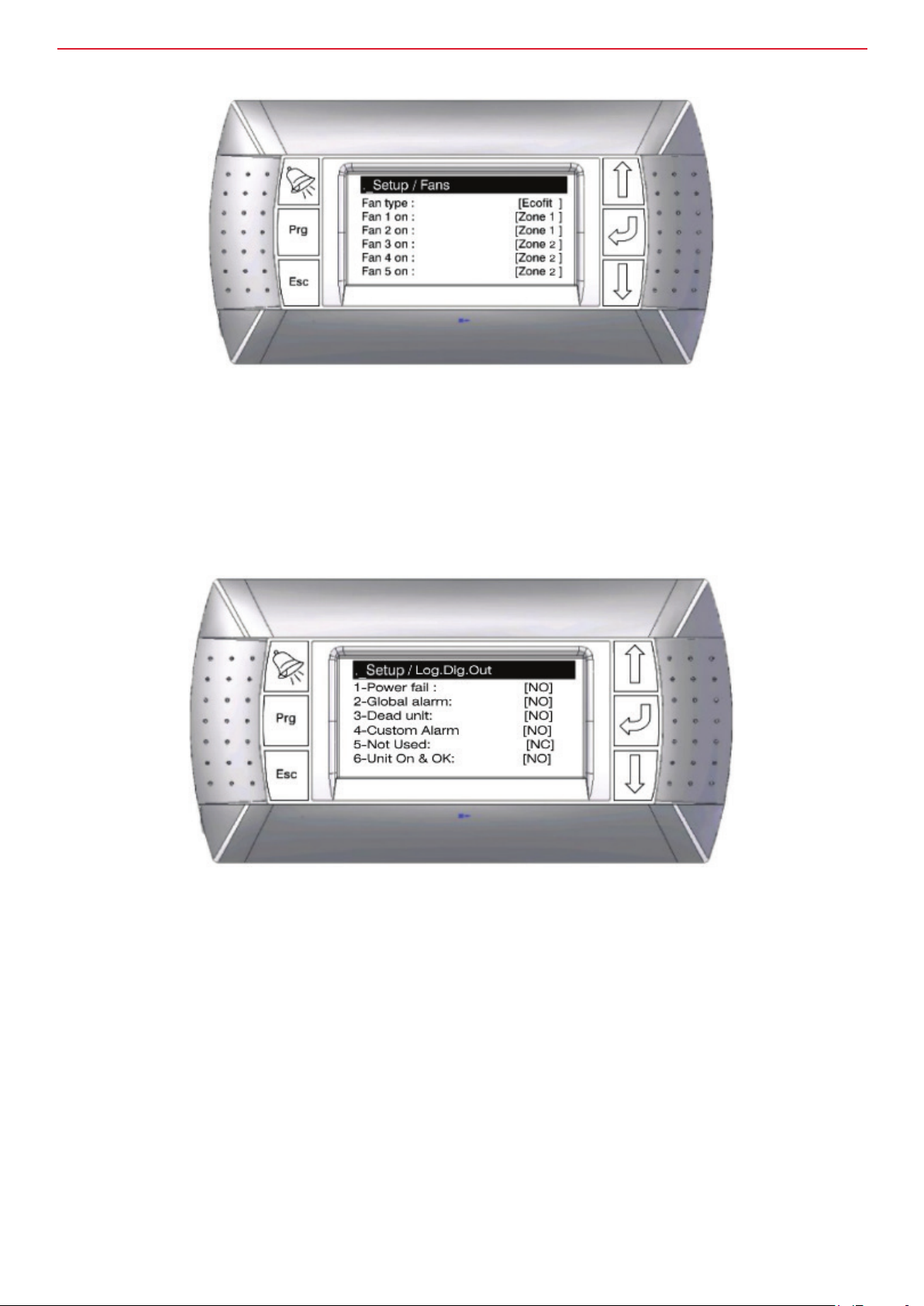
Set fan type and zones
This screen is for setting the fan type (Zeihl, EBM, Ecott etc.).
Where 2 zone or 3 zone control has been selected, the different fans can be set-up to different zones.
The fans command wire will still need to be changed to the appropriate Y1, Y2 or Y3 output.
Set digital outputs
The CPCO has 6 digital outputs. Some are pre-congured and some are adjustable.
1 refers to NO1 on the CPCO mini, and 2 refers to NO2 on the CPCO etc...
In set-up they can be changed from NO to NC and vice versa.
Default values and functions are tabled on the next page.
nVent.com/SCHROFF | 45

InstallatIon and maIntenance guIde
Digital out Default value Notes
1 – Power fail NO Closed when power supply B is running
2 – Global alarm NO Closed when any alarm has been activated
3 – Dead unit NO Closed when unit is running
4 – Custom Alarm NO See below
5 – Not used NC This can be set to ‘not used’, ‘cold aisle’, ‘custom
alarm’ or ‘leak alarm’ – See Digital input settings.
6 - Unit On & OK NO This drives the LED on the unit
Digital input set-up
Logic DIN 01 is the input from the power board that noties the CPCO that the power has changed from A to B.
I.e. the primary power input has failed.
The function of DIN 02 can be changed.
It can be ‘not used’, ‘ColdAisle’, ‘Cust. Alarm’ or ‘Leak Alarm’.
Changing this will also change digital output no. 5 in the status menu and the digital output set-up screen
(see previous page).
nVent.com/SCHROFF | 46

InstallatIon and maIntenance guIde
Custom alarm set-up
The custom alarm can be used to set an alarm when an input is received to ID2 on the front on the CMS.
This must in the form of a volt free contact. Where the custom alarm has been selected for DIN 02, an
additional screen becomes available so that the text that is displayed when the input has been activated
can be adjusted.
Example of text reset screen for custom alarm (left) and alarm output (right)
nVent.com/SCHROFF | 47

InstallatIon and maIntenance guIde
Cold Aisle set-up
The cold aisle feature is currently unsupported.
Please do not use it.
Leak alarm
Setting DIN02 to leak alarm enables an alarm when a leak is detected (see leak detection option on page 41 for wiring).
For this to work an optional leak detect board must be installed in the CMS and leak tape connected to the inputs.
When a water leak is detected an alarm will be raised by the CMS.
Set-up of the valve feedback alarm
When valve feedback has been enabled in the set-up/probes screen (page 63) the valve feedback alarm
set-up menu becomes available.
The valve feedback shows the position of the valve opening. This alarm checks the actual valve position
with the valve position that is being commanded by CMS.
It raises an alarm if there is a misalignment.
AIN09 is reference to universal input 9 on the CPCO, which is the connection Y3 on the front on the CMS.
The alarm delay time setting is the amount of time the systems waits before raising the alarm after the
alarm limit has been reached.
This is required as the valve may take some time move and thus prevents mis-alarms.
In the example show on the screen, if there is a difference of greater than 15% between valve command
and valve feedback for a time period of 30 seconds, an alarm will be raised.
nVent.com/SCHROFF | 48

InstallatIon and maIntenance guIde
Air-on alarm
This screen allows the set-up of an alarm to warn of possible re situation.
The trigger temperature is selectable between 70°C and 100°C.
Set-up contact details
Press enter to edit the name / number.
Probe calibration
This screen allows the NTC temperature and humidity probes tted to the CMS to be calibrated or have off-
set values applied.
nVent.com/SCHROFF | 49

InstallatIon and maIntenance guIde
Erase alarm log
The alarms logs can be cleared here.
The buzzer (which sounds on the CMS commissioning tool) can be disabled also.
Units of measurement
This screen can be used to change the temperature units of measurement from degrees centigrade to
degrees Fahrenheit.
Fan delay
When the DL jumper (inside the CMS unit under the Alarm Indicator) is set to ON, a hardware fan delay is applied.
An additional fan delay can be added using this display.
It can be set by the second from 0 to 120s.
nVent.com/SCHROFF | 50

InstallatIon and maIntenance guIde
Energy meter
If you have the energy meter enabled (see page 61 for enabling and pages 42 – 43 for wiring) you will need
to set the address here.
The E meter 3 by default is address 20.
You can also reset the device from here.
Control
The control menus can be accessed from the main menu.
nVent.com/SCHROFF | 51

InstallatIon and maIntenance guIde
Thermistor functions
Fan speed and valve opening is controlled by the temperature readings on thermistors.
Higher temperatures will result in higher fan speeds or more open valves. Refer to the table below for which
fans and valves are controlled by which thermistors.
The table below also shows thermistor functions other than fans and valves.
Thermistor Control strategy Sensor control / monitoring
NTC0 Z1 NA for 6 fan systems* / Cabinet front temperature
NTC1 Z1 Zone 1
NTC2 Z1 NA
NTC3 Z1 NA / text changeable for monitoring
NTC0 Z2 NA for 6 fan systems* / Cabinet front temperature
NTC1 Z2 Zone 1
NTC2 Z2 Zone 2
NTC3 Z2 NA / text changeable for monitoring
NTC0 Z3 NA for 6 fan systems* / Cabinet front temperature
NTC1 Z3 Zone 1
NTC2 Z3 Zone 2
NTC3 Z3 Zone 3
NTC0 AV NA for 6 fan systems* / Cabinet front temperature
NTC1 AV Valve control
NTC2 AV Fan control
NTC3 AV NA / text changeable for monitoring
NTC0 System NA for 6 fan systems* / Cabinet front temperature
NTC1 System Fan control
NTC2 System Valve control (NTC2 on return water pipe)
NTC3 System NA / text changeable for monitoring
*Adjusted by jumper on taco board and in software settings. NTC 0 is either Fan 6 feedback or NTC0.
nVent.com/SCHROFF | 52

InstallatIon and maIntenance guIde
Fan control
Regulation / zone 1
The Y1 terminal on the CMS is the output to all the fans when in single zone control.
It is controlled by a temperature sensor situated on the top fan panel (fan 5).
The set-point is the temperature from which you wish to start increasing the fan speed whilst the
differential temperature is the range over which the fans will increase from minimum speed to maximum
speed. In the example, 22C and below would result in minimum fan speed min whilst 27C (22 + 5) and
greater would result in the maximum fan speed.
Regulation type P= Programmed. PID =Programmed Integral Derivative.
Programmed regulation (P) controls as per the graph.
In the example the minimum fan speed has been set to 18% and the maximum fan speed to 60%.
PID attempts to anticipate future temperatures based on the values previously read.
Integral time is the period over which the CMS will cycle the change required. Derivative time is the period
over which the CMS will hold the instruction before resetting and re-issuing the instruction.
For example, integral and derivative times could be 300 seconds and 20 seconds respectively.
NOTE: It can take 15-20 cycles before the fans stabilise.
nVent.com/SCHROFF | 53

InstallatIon and maIntenance guIde
Zone 2 control
You will get additional screens for each fan zone where enabled.
Zone 2 fans are controlled by Y3 terminal output from the CMS and the temperature control is from NTC2.
Zone 3 fans are controlled by Y2 output from the CMS and temperature control is via NTC3.
2 zone and 3 zone control is only available when the valve feedback is disabled the Y3 jumper on the Tacho board must be changed to ‘ON’ and the valve feedback must be disabled in software
(see set-up).
nVent.com/SCHROFF | 54

InstallatIon and maIntenance guIde
Valve control
Valve control is only available when set into system control or AV control.
The 0-10V command signal for the valve is output via Y2 on the CMS.
In system control the valve is controlled by NTC2.
This thermistor is usually located on the return water pipe.
In AV control the valve is controlled by NTC1 and as such the valve is controlled by the air-off temperature.
The set-point temperature is the temperature from which you wish to start opening the water valve.
NOTE: If the chiller output is on, then the valve set-point is reduced by the reduced differential.
I.e. in the example the set-point is 22C and the reduced differential is 2C, so the valve controls to 20C.
Differential is the temperature range over which you wish the valve to increase from minimum opening to maximum.
In the example the minimum opening will be at 22C and below, and the maximum opening will be at 24C and above.
Regulation type P= Programmed. PID =Programmed Integral Derivative.
Programmed regulation (P) controls as per the chart.
In the example the minimum valve opening has been set to 20% and the maximum to 80%.
PID attempts to anticipate future temperatures based on the values previously read.
Integral time is the period over which the CMS will cycle the change required.
Derivative time is the period over which the CMS will hold the instruction before resetting and re-issuing the instruction.
For example, Integral and derivative times could be 300 seconds and 20 seconds respectively.
NOTE: It can take 15-20 cycles before the valve stabilises.
nVent.com/SCHROFF | 55

InstallatIon and maIntenance guIde
Chiller regulation for zone 1, zone 2 and zone 3 control
This control feature is the NO4 VFC output and is usually used to send a signal to the chiller (usually to
lower the water temperature) once the fan speed and/or valve opening thresholds have been exceeded.
Regulation/chiller, zone 1/2/3 mode
The threshold is the point you wish the chiller to be triggered – in this case when the fans are at 100%.
The differential is the deadband you wish to apply – in the example, if the fans have triggered the chiller by
getting to 100% fan speed, the chiller output will not stop until the fan speed has dropped to 90%.
The delay is the time period you wish to hold before triggering the chiller to drop its water temperature.
‘Activate on’ setting is used when you have multiple zones.
If you wish either of Z1, Z2 or Z3 fans to trigger the chiller to drop its water temperature then set to ‘Any’.
If you require all zones to reach the threshold to drop the chiller temperature, then set to ‘All.’
NOTE: The regulation / chiller parameters determine when to change the chiller set-point (i.e. drop the
water temperature). The algorithm looks at the demands of both zones (see ‘Activate on’ above).
nVent.com/SCHROFF | 56

InstallatIon and maIntenance guIde
Chiller regulation for AV and system control
Chiller regulation for AV and system control is slightly different as we have both a valve and fans available.
When both valve openings and fan output are high the system may be struggling to cool the equipment
contained within the rack. Similarly to Z1/Z2/Z3 control, a VFC signal to the chiller (usually used to drop the
water temperature when the system is struggling and consequently improve cooling output) is sent when a
combination of valve opening position and fan output command has been exceeded.
When the fans and valve opening have decreased by a certain amount (dead-band or valve diff.) the VFC
signal output is cancelled.
In the example, when the fan speed has exceeded 73.3% AND the valve opening has exceeded 75%, the
NO4 chiller output will be triggered.
Once triggered, it will not be cancelled until the valve opening as dropped to 74% and the speed has dropped to 63.3%.
The delay can be used to prevent the chiller output for a certain period of time whilst the trigger thresholds
have been exceeded.
nVent.com/SCHROFF | 57

InstallatIon and maIntenance guIde
Control of fan alarm
The fans RPM is monitored and a feedback signal is provided (see status).
When the feedback value doesn’t match with what is expected an alarm will be raised.
There is a delay on the alarm to prevent false alarms – for example, when the system starts up the fans are
at rest, and without an alarm delay the expected fan feedback and actual feedback would be mismatched
resulting in an instant alarm.
The minimum and maximum fan speed command can also be set on this menu.
Fan fail diff Sets a tolerance for the difference in rotations and eliminates spurious fan alarms.
Fan fail delay Sets the time delay before the alarm is triggered.
Start alarm delay Sets the period on initial start-up before any alarms are triggered.
Fan min speed Sets the minimum speed fans will run at.
Minimum speed should be 13% or above.
If the fans are set below these recommendations the airflow way be too low for correct fan function and
will also cause spurious alarms.
nVent.com/SCHROFF | 58

InstallatIon and maIntenance guIde
Fan cut-off control
If the system temperature is at the fan set-point, the temperature may be considered low enough that
the fans aren’t required. This situation commonly occurs with installations that have no equipment that
requires cooling yet, but will in the near future. In this case, running the fans would just be a waste of
energy and this function can be used to stop the fans.
Enabled is used to enable or disable this feature.
The thermistor that is used to monitor the temperature can be:
‘Air on / Air off’, ‘Air on/off/cabinet front/aisle’, ‘air on/off/cabinet front’.
When the temperatures measured at the thermistors reach the fan set-point, the fans will stop.
The differential is the amount above the set-point that will cause the fans to restart.
For example, if the fan set-point is 23C and the differential 1C, then the fans will restart at 24C.
nVent.com/SCHROFF | 59

InstallatIon and maIntenance guIde
High low control temperature
This feature will raise an alarm if the temperature rises signicantly above or below the set-point.
This will likely be the result of over cooling or under cooling and will warrant an investigation into system
performance or to see if there has been a failure.
Alarm differential is the temperature above and below the set-point at which an alarm is triggered.
Alarm delay is the time period the temperature is above or below the threshold before an alarm is sent.
If the temperature returns to normal levels before the delay period has expired, no alarm will be sent.
It is expected that the regulated temperature will remain within a temperature band dened by calculations
based upon power consumption gures supplied by the customer.
Over / Under temperature alarms do not auto clear from the CMS. They must be manually reset.
nVent.com/SCHROFF | 60
InstallatIon and maIntenance guIde
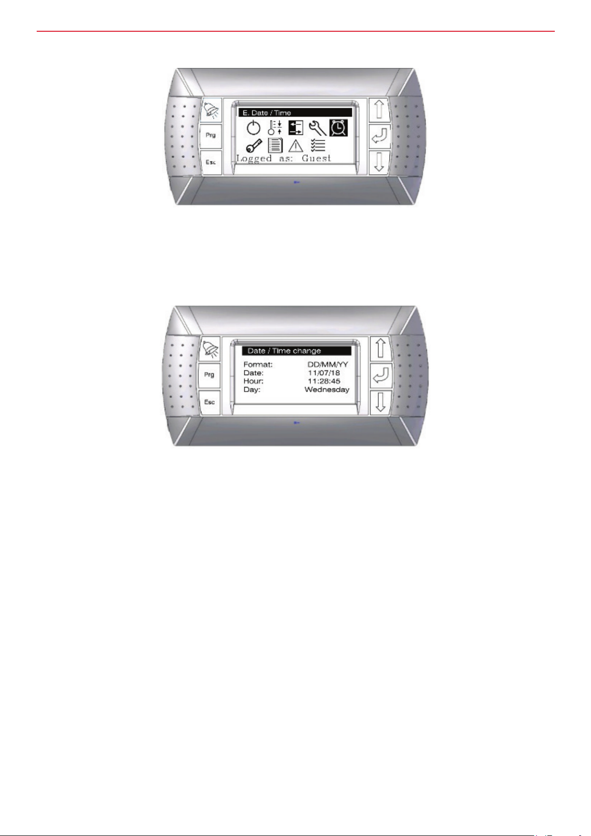
Date and time set-up
Date and time adjustment can be accessed from the main menu and adjusted using the cursor and enter
keys.
nVent.com/SCHROFF | 61

InstallatIon and maIntenance guIde
Data logger
The data logger is a record of previous alarms. They can be cleared in the set-up/erase alarm log menu
(see page 49 ‘Erase alarm log’).
nVent.com/SCHROFF | 62

InstallatIon and maIntenance guIde
Preventative maintenance warnings
There are 3 types of preventative maintenance warnings:
1. Text warnings or advice, for example, check water lter
2. System checks that check component performance.
Components are checked during use but there are times when cabinets are left dormant for some length of time.
These maintenance procedures can be set to periodically check the fan function and valve function.
3. Testing of alarms.
This is a periodic function that can be used to ensure that the BMS and/or RMS systems can, and are,
monitoring alarms.
The preventative maintenance menu can be accessed from the main menu screen.
Text warnings / advisories
These are periodic text alarms that alert the end user.
They are usually used to ensure that regular servicing and maintenance are carried out.
PM warnings – clean coil
Allows a warning to be set for preventative maintenance of cooling coil cleanliness.
The periodic alarm can be enabled by setting ‘Enable Warnings’ to ‘Yes’ or ‘No’. Warning limit sets the
frequency of the warning (in days). ‘Last reset’ automatically records when the warning was last made.
When the alarm is raised and subsequently cleared (by pressing the alarm button), the alarm is logged and
the warning limit counter is reset to zero. ‘Reset warning’ will reset the counter to zero when set to ‘Yes’.
nVent.com/SCHROFF | 63

InstallatIon and maIntenance guIde
Other PM warnings than can be set in a similar way are:
• Renew service contract
• Check lter (water lter/strainer)
• Periodic message with customised text
System checks
Check fan. This feature periodically checks the fan to make sure that the fans are working correctly.
It is possible for fans to rotate even when they have failed and this check will ensure all fan failures are captured.
Screen 1 of 2 for fan speed check
The periodic test can be enabled by setting ‘Enable Warnings’ to ‘Yes’ or ‘No’.
Warning limit sets the frequency of the test (in days). Use ‘Test time’ to set the time that you want the test
performed. ‘Last reset’ automatically records when the test was last made.
Screen 2 of 2 for fan speed check
Set Enable Al lock if the cabinet is required to lock in alarm when a fan fails this test.
This will require someone to investigate and cancel the alarm.
Set ‘Time min speed’ to run the fans at minimum speed – ensure this time is sufcient to allow the fans to
slow and keep a stable speed as they may be running at or near their maximum.
Set ‘Time max speed’ to run the fans at maximum speed – ensure this time is sufcient to speed the fans
up and keep a stable speed.
Set the delay before failure alarm is triggered – this should be just less than the higher of the min and max time periods above.
The alarm cannot be reset in the usual way when the Al lock is enabled (i.e. by holding alarm button).
Another system check that works in a similar way is the check valve feature.
nVent.com/SCHROFF | 64

InstallatIon and maIntenance guIde
Alarm checks
Alarm checks are used to ensure that alarms are being registered on connected BMS and RMS systems, or
simply to check the alarm function.
The periodic test can be enabled by setting ‘Enable Warnings’ to ‘Yes’ or ‘No’.
Warn mode is used to set the time period between tests – i.e. number of days/months or even monthly/weekly.
Warning limit sets the frequency of the test.
Use ‘Test time’ to set the time that you want the test performed.
‘Last reset’ automatically records when the test was last made.
nVent.com/SCHROFF | 65

InstallatIon and maIntenance guIde
Central Management System (CMS)
CMS controller – CMS display pairing
The CMS and CMS controller will come from the factory working.
However, sometimes after upgrades the commissioning tool screen may cease to work.
In this case please perform the following procedure.
1. Ensure the controller is connected to the CMS unit and powered up.
2. Press the three keys on the right hand side together.
The screen below will then be shown
NOTE: The default address for the commissioning tool is 32. The default address for the cpco mini is 01.
Change the display address to 32
1. Press enter and use the cursor keys to select 32.
2. Press enter to accept
3. Set the I/O board address to 01 and press enter to accept. The Terminal config screen will be shown – press enter again.
nVent.com/SCHROFF | 66

InstallatIon and maIntenance guIde
1. Trm1 use the cursor keys to select 32. Press enter to accept.
2. Press enter to accept Pr.
3. Trm 2 press enter to accept ‘None’ and then press enter to accept ‘--’.
4. Trm 3 press enter to accept ‘None’ and then press enter to accept ‘--’.
5. Use the cursor keys to select ‘Yes’ on the ‘OK?’ option and enter to accept.
10. If you accept ‘No’, it will return you to the top.
NOTE: If you don’t press any buttons for 30 seconds, the system will cancel this set-up procedure and you
will have to start again.
nVent.com/SCHROFF | 67

InstallatIon and maIntenance guIde
CMS circuit diagram
nVent.com/SCHROFF | 68

InstallatIon and maIntenance guIde
RackChiller Water software – CPCO mini inputs and outputs table
CPCO
connection
Type Device/Label Comment
U1 0-10V input Feedback Fan1
U2 0-10V input Feedback Fan2
U3 0-10V input Feedback Fan3
U4 0-10V input Feedback Fan4
U5 0-10V input Feedback Fan5
Feedback Fan6
OR
Thermistor / NTC0
U6
0-10V input
Resistance input
U7 Resistance Thermistor / NTC1
U8 Resistance Thermistor / NTC2
Cabinet Front OR Room temperature when
NTC0
Set Fan6/NTC0 jumper on Taco board and
set in software
Temp Zone 1 OR Temp Air off
Controls fan in system control
Controls valve in AV control
Temp Zone 2 / Temp Return Water Controls
valve in system control
Temp Air on
Controls fan in AV control
Valve feedback OR
Y3 / Zone 2 fan
command
Set Y3 dip switch on Taco board to ‘ON’ for
Zone 2 Fan Bank
U9
0-10V input
0-10V output
Temp Zone 3 OR other temperature
U10 Resistance NTC3
CPCO Mini
measurement, text is changeable in
software
ID1 VFC Power A-B
ID2 VFC Custom Alarm Various input functions
Fan command OR
Y1 0-10V Output
Zone 1 fan
Main fan command output
command
Y2 0-10V Output
Valve command OR
Zone 3 Fan
Main valve command output
command
NO6 VFC Blue LED output Unit Healthy (On and No Alarm)
NC6 VFC Red LED output Unit NOT Healthy (alarm state)
NO2 VFC Global Alarm
NO3 VFC
NO4 VFC
NO1 VFC
CPCO running
output to Taco
Custom Alarm OR
Chiller demand
Power Failure –
running on B supply
Dead unit/power failure
I.e. Running on UPS
NO5 VFC Custom Alarm
FieldBus1 RS485 Serial Probes 1-7
Modbus RS485
/ Modbus IP /
BACNET IP
BMS1
RS485 OR
Ethernet
(AirOn / AirOff / Temp Cabinet Front /
InAisle / DewPoint )
BMS connection, High end CPCO has
ethernet, Enhanced is Modbus
J3 Display Connection to pGD1 commissioning tool
nVent.com/SCHROFF | 69

Notes
Our powerful portfolio of brands:
CADDY ERICO HOFFMAN RAYCHEM SCHROFF TRACER
©2018 nVent. All nVen t marks and logos a re owned or licens ed by nVent Servic es GmbH or its aff iliates. All other t rademarks are th e property
of their res pective owners . nVent reserves the r ight to change spe cifications wi thout notice.
XXXXXX_1807
nVent.com/SCHROFF
 Loading...