

Page 1

General
Installation Introduction
This document is provided as a general guide to playground installation. Each structure will include an
install sheet specifically made for that particular structure.
PLEASE NOTE THE FOLLOWING:
STORAGE:
When play equipment is received at a job site it should be installed as soon as possible (within a few days from receipt).
The equipment is packaged to keep it safe and damage-free during shipment. However, the packaging material is not
suited for periods of extended storage in an uncontrolled environment. The combination of moisture from the environment
mixed with the heat generated inside the plastic wrapping may cause damage to the finish of the powder-coated items.
If an immediate installation is not possible, certain steps should be taken to minimize the risk of damage to the equipment.
If play equipment must be stored, ideally it should be kept in a controlled environment (storage container, inside building,
etc…) away from heat and moisture. If this is not possible, the packaging material should be removed from the
equipment, using caution so as not to damage the finish with special regard given to powder coated items.
Any large sheets of poly (panels, arch bridge panels, slide hoods, etc.) need to be stored flat or well supported to prevent
warping.
INVENTORY:
Please note that inventory should only be taken with the Packing List that ships with each job.
FOOTING INFORMATION:
The following footing guidelines are general and do not supersede any specific information given in any individual set of
drawings or instructions. Footing detail drawings are given at the end of this document. Recommended concrete
minimum: 2500 PSI.
18” Wide x 18” Deep Footing (does not include safety surfacing depth)
Vertical posts in structure (3.5” and 5”)
Most Swings (excluding 5” Single Post)
12” Wide x 18” Deep Footing (does not include safety surfacing depth)
Slide Feet / Slide Supports Ground to Deck Stair Handrails
Transfer Stations Single Steps
Lily Pads Climbers attached to Structure
18” Wide x 36” Deep Footing (does not include safety surfacing depth)
Single Post Swing (5”)
Page 2

We recommend that you build your modular structure in a radiating fashion. This means that you will start with a single
post or deck assembly located at the core of the structure creating a central backbone to build outward from. Erect this
post or deck assembly with the posts in the footings but not concreted into place. After completing this task you will be
able to radiate outward in all directions with the remaining decks, bridges, crawl tunnels, overhead events and modular
components. We recommend you use the ACTUAL PARTS to locate the vertical post locations ALONG with the
FOOTING LAYOUT drawing provided.
There may be situations or special circumstances that will require you to use your own judgment. If you have any
questions or are unsure about a situation, please contact your local Sales Representative.
Taking the time to read these instructions in their entirety will help ensure that your equipment is assembled correctly,
maintained properly and enjoyed with proper adult supervision so that children can enjoy it for years to come.
PLAYGROUND SITE PREPARATION:
Using the provided plan view drawing of your playground, locate all structures within your site making sure that the
placement of the structures meets all required clearances.
All asphalt, concrete and other such hard debris must be removed from the entire site prior to installation.
Site must be graded as close to level as possible to create the safest possible environment for the playground. Special
installation considerations must be implemented for sites that are not level.
Check local soil and drainage conditions within the site area. Proper drainage around the structures and their supports is
important. Inquire with local contractors in your area for the proper recommendations.
Check with local authorities regarding building codes, permit needs, requirements, etc. before beginning installation.
Site must be isolated from hazards such as swimming pools, ponds, lakes, other bodies of water, highways, roads, dropoffs, cliffs, etc. A method to contain children must be provided that still allows for observation by supervisors. If fences
are used, they should conform to local building codes and/or ASTM F-2049.
Site should be surveyed and marked for underground utilities prior to excavation.
Never leave the job site unattended without making sure that all open holes are covered with a material such as plywood.
Rope off all unfinished equipment to keep the children away until the build is complete.
PRE-INSTALLATION CHECK:
Compare all items received to the main packing list. Notify your sales representative immediately if any parts are missing
or damaged. We are not responsible for items discovered missing after 72 hours from time of delivery!
COMMON INSTALLATION TOOLS
A) 9/16” Wrench
B) Wheelbarrow (to mix concrete)
C) High Speed 3/8” Electric Drill w/clutch with 1/4” and 1/2” Bits
D) String Level, Magnetic Level, 4’ Level
E) Large Flat Head Screwdriver
F) Mallet
G) Hack Saw
H) Impact Gun
I) Shovel / Post Hole Digger / Auger
J) Pry Bar
K) Tape Measure
L) 3/16” and 1/4” Allen Head Wrench
M) T-45 TORX Tool (supplied by the manufacturer)
N) T-30 TORX Tool (supplied by the manufacturer)
O) Straps and boards to help hold structure in a level position before and while concrete sets.
Page 3

SAFETY AND CLEARANCE STANDARDS AND GUIDELINES:
Our play equipment is engineered and designed based on the most current ASTM F1487 standard.
For information regarding public playground safety and your responsibilities as the purchaser, manager or installer of this
equipment, we recommend you contact the U.S. Consumer Product Safety Commission (CPSC) for the latest copy of the
Public Playground Safety Handbook. You may obtain a copy of this guidebook by contacting the CPSC at 800-638-2772,
or by visiting their website at www.cpsc.gov.
The playground area, both around and underneath the structure, must be covered with impact attenuating surfacing
material. The surfacing material used should have a Critical Height Value of at least the height of the highest designated
play surface on the equipment. The critical height for surfacing is to be rated in accordance with the most current version
of ASTM F1292. To purchase a copy of ASTM F1292, Standard specification for impact attenuation of surface systems
under and around playground equipment, contact American Society for Testing and Materials (ASTM) by calling 610832-9585, or by visiting their website at www.astm.org. This information is also given in the Public Playground Safety
Handbook. Additional considerations for protective surfacing materials are given as well.
Acceptable playground surfacing materials are available in two basic types: unitary or loose-fill. Contact the manufacturer
of unitary surfacing materials (rubber matting) for the critical height rating for their products. If loose-fill surfacing
materials are used, please refer to the Public Playground Safety Handbook published by the CPSC for critical height
values for tested materials. We recommend a minimum depth of 12” for our play equipment.
Never add components that are not approved by the manufacturer.
If relocation of any equipment is desired that differs from the drawings and/or site plan that was provided, prior written
approval from the manufacturer must be obtained. Failure to do so may create a dangerous play environment for children.
If individual pieces of equipment are ordered as parts only (without being placed in a site plan drawing), it is the
responsibility of the customer/installer to determine the appropriate use zone needed for that equipment. Contact your
local sales representative to get this information.
If you have any doubt about the correct placement of any piece of equipment, please contact your sales representative to
get clarification.
Unless specified otherwise, the fall height of a piece of equipment is the distance between the highest designated playing
surface and the protective surfacing beneath it.
The use zone for equipment should extend a minimum of 6’ in all directions from the perimeter of the equipment.
The use zones of two stationary pieces of playground equipment that are positioned adjacent to each other may overlap of
the adjacent designated play surfaces of each structure are no more than 30” above the protective surface and the
equipment is at least 6’ apart.
If adjacent designated play surfaces on either structure exceed a height of 30”, the minimum distance between the
structures should be 9’.
Use zones of the play equipment will be shown in the plan view drawing and must be adhered to. The fall height of the
equipment will also be given in the drawing.
Page 4
INSTALLATION GUIDELINES
Excavate holes in accordance with footing drawing. If the site cannot be graded level, adjust the depth of footings to
maintain a level footing base. If soil conditions are loose or unstable, a larger diameter footing may be required.
As mentioned earlier, we recommend that the equipment be built in a radiating fashion from a central post. After verifying
equipment will fit in area as shown on drawings, locate and set central post in footing hole.
Assemble the entire structure before pouring the concrete, using the equipment to place vertical posts (verify using footing
drawing). This will be the procedure unless otherwise instructed per the individual instruction. After completing
assembly, make sure structure is level and plumb across the board before pouring concrete. Concrete with a minimum PSI
of 2,500 must be used, and should be mixed in accordance with manufacturer’s specifications.
Never leave the installation site unattended without making sure that all fastening hardware on all equipment is tight.
Failure to do so may result in injury or component damage.
All installation areas should be roped off with clearly marked warning signs posted. Even during installation, it has been
found that children will use unattended equipment - thereby risking accidents. Do not attach swing chains, exercise rings,
or similar moving components until entire construction is complete and safety surfacing is in place. Remember that any
equipment that appears to be complete will invite unauthorized usage regardless of its actual state of readiness.
Keep installation site roped off for at least 48 hours before equipment usage to allow concrete to harden.
We recommend you have a Certified Playground Safety Inspector (CPSI) on site during installation. At a minimum, a
CPSI should inspect your structure after installation and safety surface is in place and prior to children playing on the
playground.
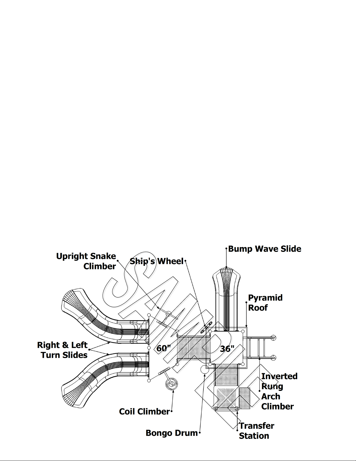
Typical Overhead Layout View
Page 5
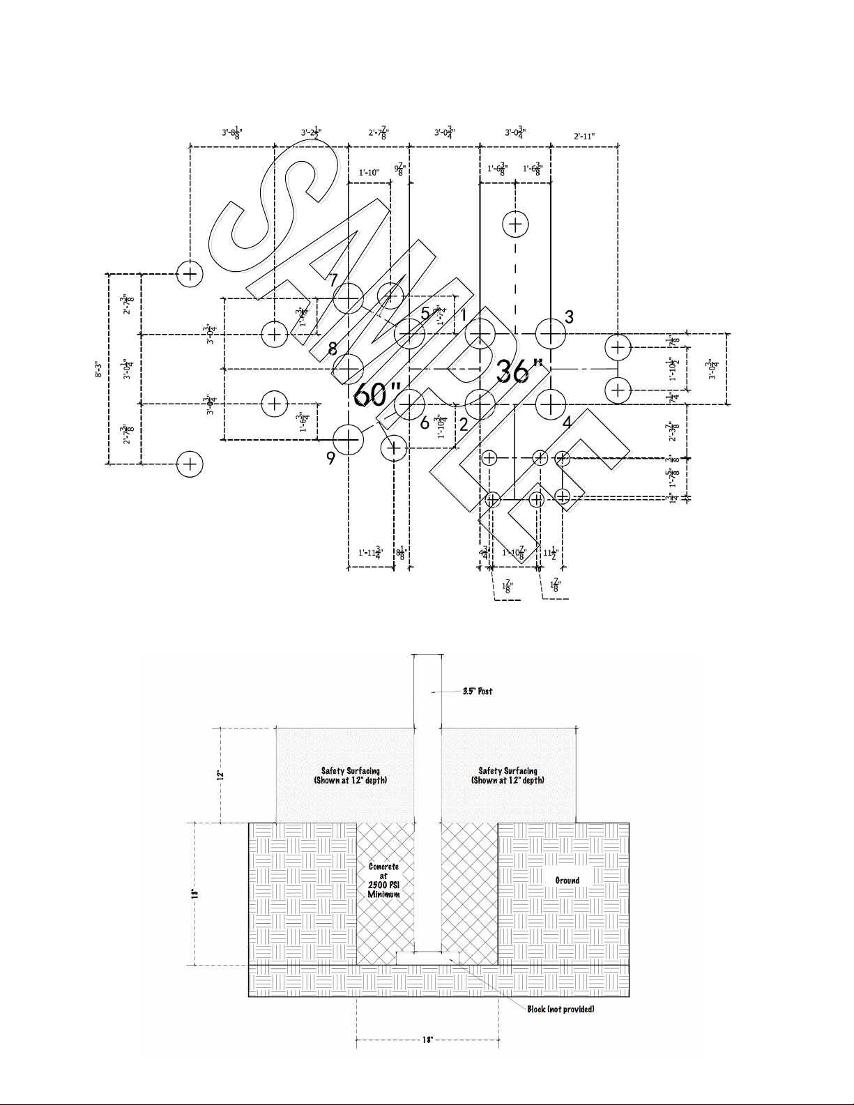
Typical Footer & Post Layout Diagram
Example of Footer
Page 6
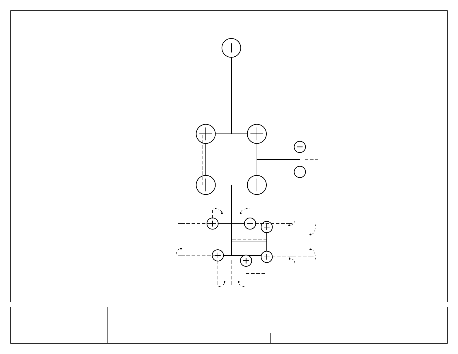
February 13, 2019
PKP028 Patriots Point
Footer and Post Layout
Footer Layout provided as a guide. Measurements rounded to nearest
1/2 inch. For true accuracy, please measure using equipment onsite.
Equipment dimensions are subject to change without notice.
31"
9"9"37"
28"
13"
9-1/2"
13-1/2"
13-1/2"
25-1/2"
9-1/2"
10-1/2"
15"
10-1/2"
10-1/2"3"2-1/2"
62"
36"
Page 7
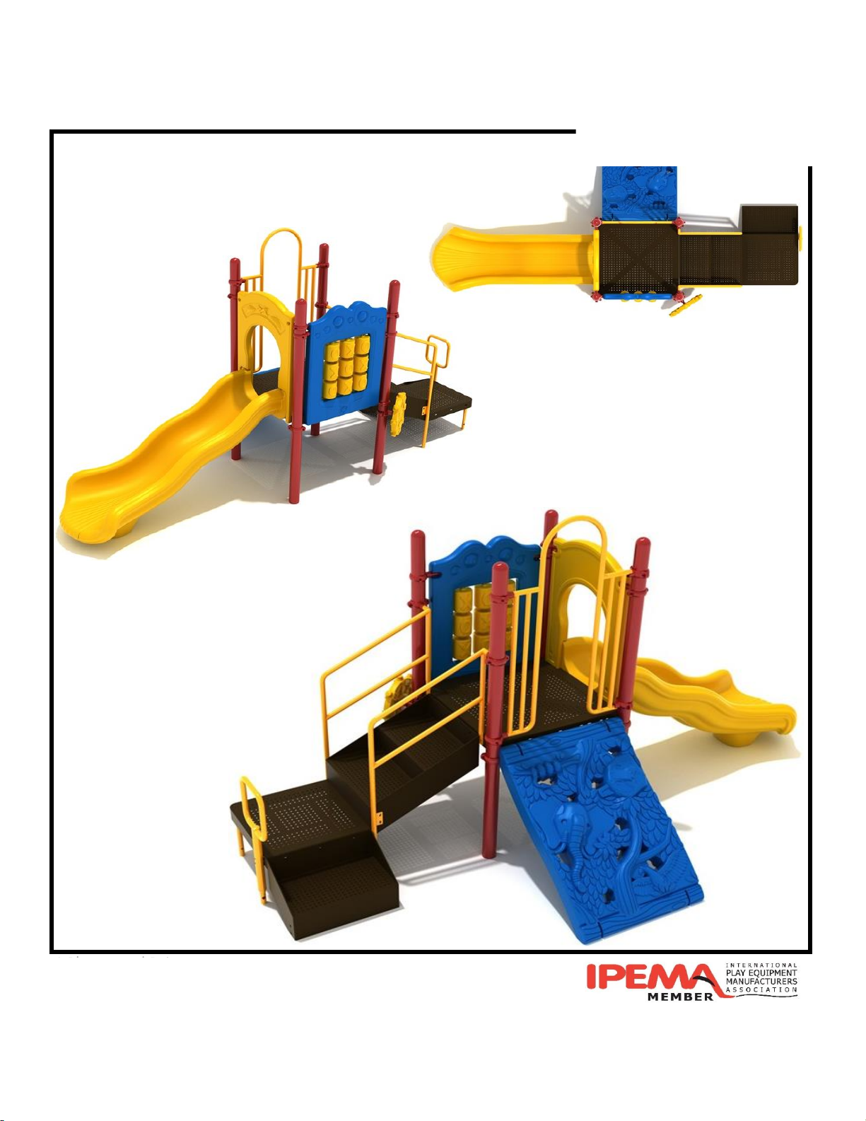
PKP028 Patriot's Point Packing List
1 Playground Drive
Greenfield, IN 46140
1-800-667-0097
Page 8
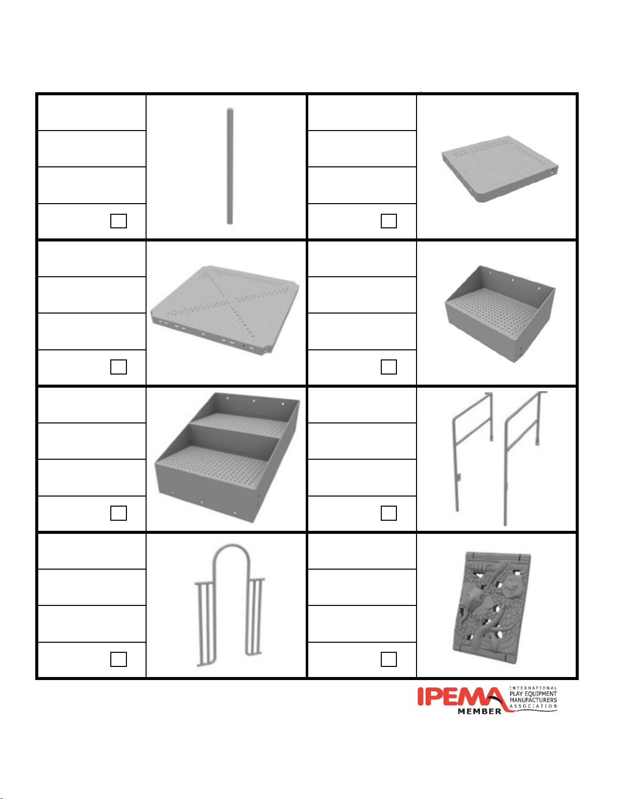
Post Transfer Deck
Brick Red PVC Coated
QTY: 4 QTY: 1
Complete Complete
89-Square Deck Transfer Step
PVC Coated PVC Coated
QTY: 1 QTY: 1
Complete Complete
3' Transfer Stair Transfer Stair Rail
PVC Coated Sunglow Yellow
QTY: 1 QTY: 1 pair
Complete Complete
4-Clamp Arch Entry Jungle Climber
Sunglow Yellow Pacific Blue
QTY: 1 QTY: 1
Complete Complete
1 Playground Drive
Greenfield, IN 46140
1-800-667-0097
181204-GB-1-CR013 Packing List
Page 9
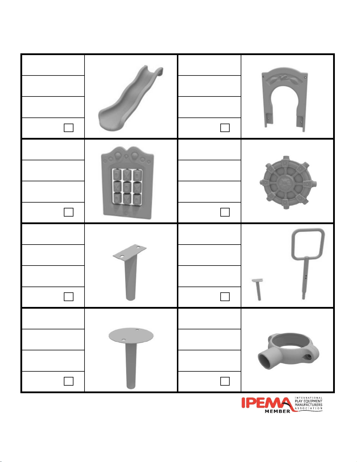
3' Wave Slide Slide Hood
Sunglow Yellow Sunglow Yellow
QTY: 1 QTY: 1
Complete Complete
Tic-Tac-Toe Panel Ship's Wheel
Blue Panel
Yellow Spinners
Sunglow Yellow
QTY: 1 QTY: 1
Complete Complete
Transfer Step Mount
Transfer Deck
Mount & Handrail
Sunglow Yellow Sunglow Yellow
QTY: 1 pair QTY: 1 set
Complete Complete
Slide End Mount Tube Clamp
Sunglow Yellow Brick Red
QTY: 1 QTY: 6
Complete Complete
1 Playground Drive
Greenfield, IN 46140
1-800-667-0097
181204-GB-1-CR013 Packing List
Page 10
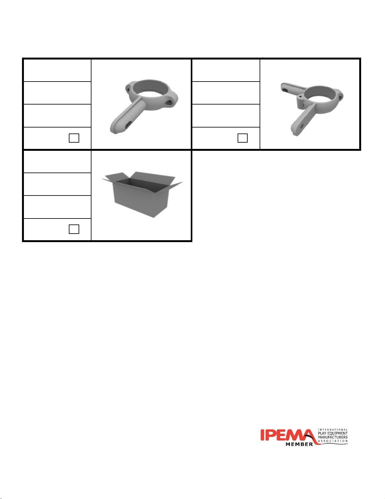
Flat Clamp 90° Flat Clamp
Brick Red Brick Red
QTY: 2 QTY: 1
Complete Complete
Hardware Box
N/A
QTY: 1
Complete
1 Playground Drive
Greenfield, IN 46140
1-800-667-0097
181204-GB-1-CR013 Packing List
Page 11
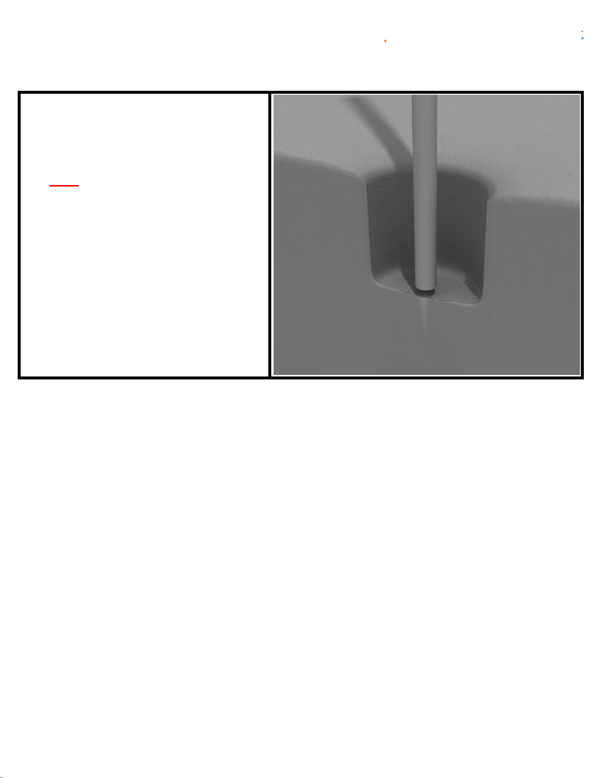
Post Installation
STEP: 1
DO NOT CEMENT POSTS INTO PLACE
UNTIL THE ENTIRE STRUCTURE IS
ASSEMBLED.
Refer to the General Installation
guide footing information and dig
proper holes for the support posts.
1 Playground Drive Created By: Aaron Price
Greenfield, IN 46140 Date: 04/26/2018
1-800-667-0097
Page 1 of 1 (Post Installation)
Page 12

Square Deck Installation
STEP: 1
After the posts are in place, using
four (4) M10*35 Bolts, eight (8) M10
Washers, and four (4) M10 Lock
Nuts, attach each square deck to
each pre-attached deck clamp as
shown in the image.
Deck clamps are pre-attached to the
posts and should not be altered in
any way.
1
Playground Drive Created By: Aaron Price
Greenfield, IN 46140 Date: 3/19/2018
1-800-667-0097
Page 1 of 1 (Square Deck Installation)
Page 13
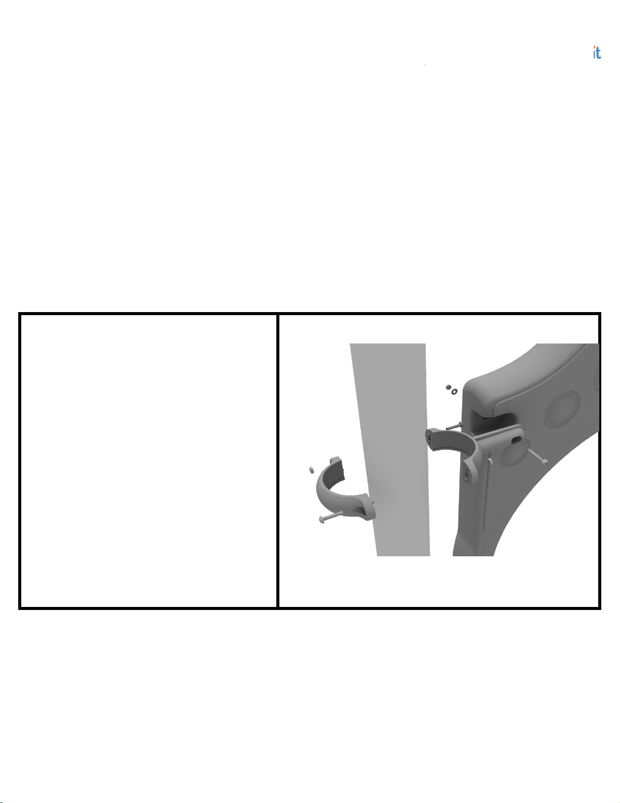
3.5-inch Clamp Installation Examples
The following three pages will include examples of how to install some of the most
common types of Clamps that are present on our structures that use 3.5-inch outside
diameter posts. The structure that you are assembling might not require all the types of
clamps listed in these examples.
The Install Guides for specific components that come later in this document might
call for a specific type of clamp (a tube clamp for example), those sections will not include
detailed instructions for the clamps and should direct you back to this section for more
detailed information.
3.5-inch Flat Clamp Install Example
Connect half of the flat clamp to the
component using one (1) M8*40
bolt. Then, using the other half of the
flat clamp and the hardware
provided in the clamp hardware bag,
attach the backside of the flat clamp
around the post.
1 Playground Drive Created By: Derick H
Greenfield, IN 46140 Date: 11/01/2018
1-800-667-0097
Page 1 of 3 (3.5-inch Clamp Installation Examples)
Page 14
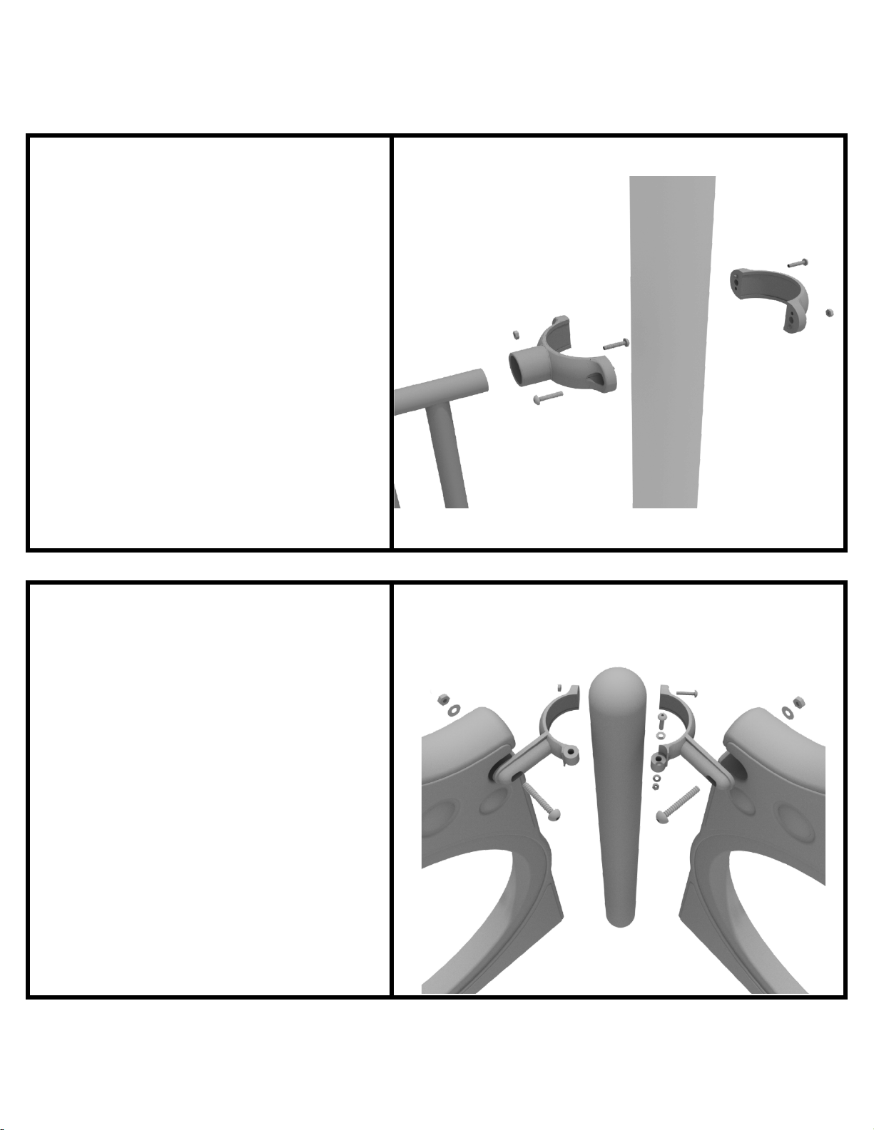
3.5-inch Clamp Installation Examples
3.5-inch Tube Clamp Install Example
Connect half of the clamp to the
component using one (1) M8*30
bolt. Then, using the other half of the
tube clamp and the hardware
provided in the clamp hardware bag,
attach the backside of the tube
clamp around the post.
3.5-inch 90-Degree Flat Clamp Install Example
Connect half of the flat clamp to one
panel using one (1) M8*40 bolt.
Then, using the other half of the flat
clamp and the hardware provided in
the clamp hardware bag, attach the
other half of the tube clamp around
the post. Then, attach the next panel
to the other side of the clamp using
the same process.
1 Playground Drive Created By: Derick H
Greenfield, IN 46140 Date: 11/01/2018
1-800-667-0097
Page 2 of 3 (3.5-inch Clamp Installation Examples)
Page 15
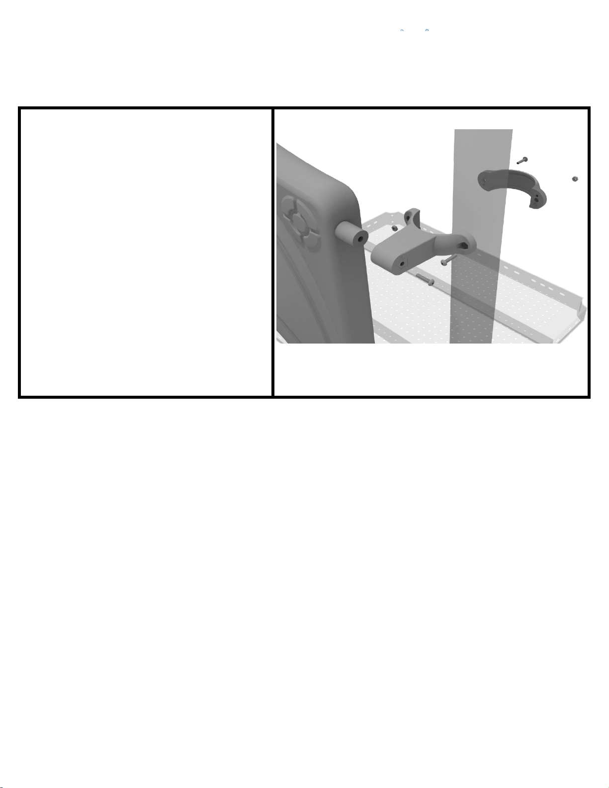
3.5-inch Clamp Installation Examples
3.5-inch Double Slide Clamp Install Example
Connect half of the double slide
clamp to the double slide hood using
one (1) M8*30 bolt. Then, using the
other half of the clamp and the
hardware provided in the clamp
hardware bag, attach the backside of
the double slide clamp around the
post.
1 Playground Drive Created By: Derick H
Greenfield, IN 46140 Date: 11/01/2018
1-800-667-0097
Page 3 of 3 (3.5-inch Clamp Installation Examples)
Page 16
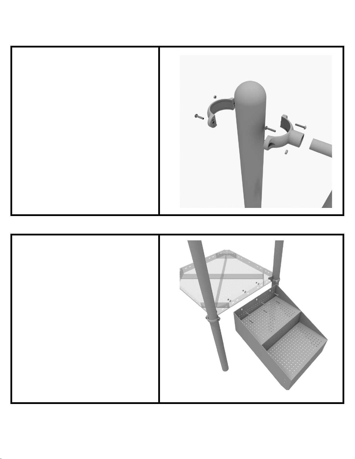
36” Transfer Station (for 3.5” post) Install
STEP: 1
Connect half of the 3.5-inch tube
clamp to the handrail using one (1)
M8*30 bolt. Set the handrail into
place, then attach the second half of
the clamp using the hardware
provided in the clamp bag. Repeat
this process for the other handrail.
STEP: 2
Using three (3) M10*25 bolts, six (6)
M10 washers, and three (3) M10 lock
nuts, attach the top of the stairs to
the square deck.
1 Playground Drive Created By: Aaron Price
Greenfield, IN 46140 Date Modified: 3/13/18
1-800-667-0097
Page 1 of 5 (36” Transfer Station (for 3.5” post) Install)
Page 17
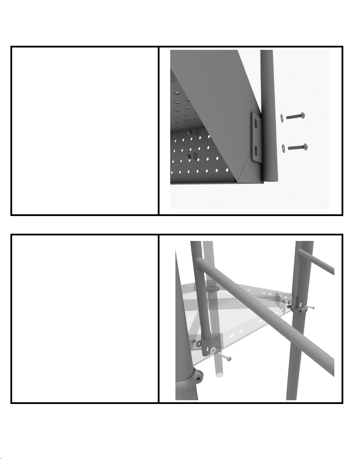
36” Transfer Station (for 3.5” post) Install
STEP: 3
Using four (4) M10*25 bolts, eight (8)
M10 washers, and four (4) M10 lock
nuts, connect the bottom of the
handrails to the bottom of the 3-foot
transfer stair.
STEP: 4
Using two (2) M10*25 bolts, four (4)
M10 washers, two (2) lock nuts,
attach the handrail to the square
deck.
1 Playground Drive Created By: Aaron Price
Greenfield, IN 46140 Date Modified: 3/13/18
1-800-667-0097
Page 2 of 5 (36” Transfer Station (for 3.5” post) Install)
Page 18
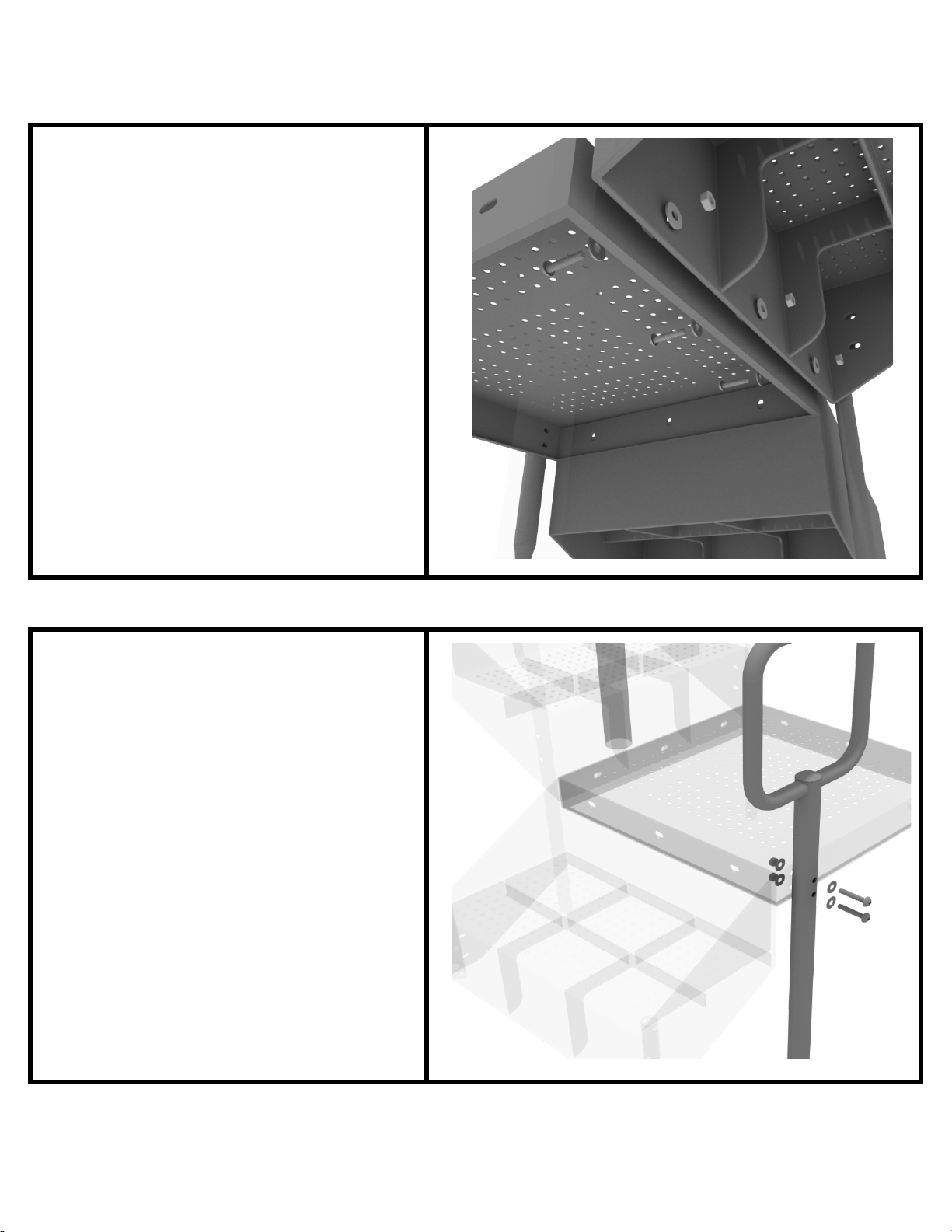
36” Transfer Station (for 3.5” post) Install
STEP: 5
Using three (3) M10*25 bolts, six (6)
M10 washers, and three (3) M10 lock
nuts, attach the ADA transfer deck to
the base of the 3-foot ADA transfer
stair.
STEP: 6
See general installation guide
regarding footing information for the
transfer deck handrail & mount.
Using two (2) M10*65 bolts, four (4)
M10 washers, and two (2) M10 lock
nuts, attach the transfer handrail to
the ADA transfer deck.
1 Playground Drive Created By: Aaron Price
Greenfield, IN 46140 Date Modified: 3/13/18
1-800-667-0097
Page 3 of 5 (36” Transfer Station (for 3.5” post) Install)
Page 19
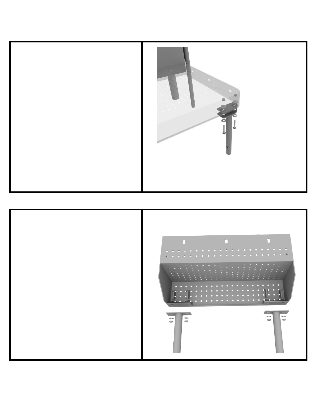
36” Transfer Station (for 3.5” post) Install
STEP: 7
Using two (2) M10*25 bolts, four (4)
M10 washers, and two (2) lock nuts,
attach the transfer deck mount to
the ADA transfer deck.
STEP: 8
See general installation guide
regarding footing information for the
ADA transfer step mount. Using two
(2) M10 bolts, four (4) M10 washers,
and two (2) M10 lock nuts, attach the
transfer step to each ADA transfer
step mount.
1 Playground Drive Created By: Aaron Price
Greenfield, IN 46140 Date Modified: 3/13/18
1-800-667-0097
Page 4 of 5 (36” Transfer Station (for 3.5” post) Install)
Page 20
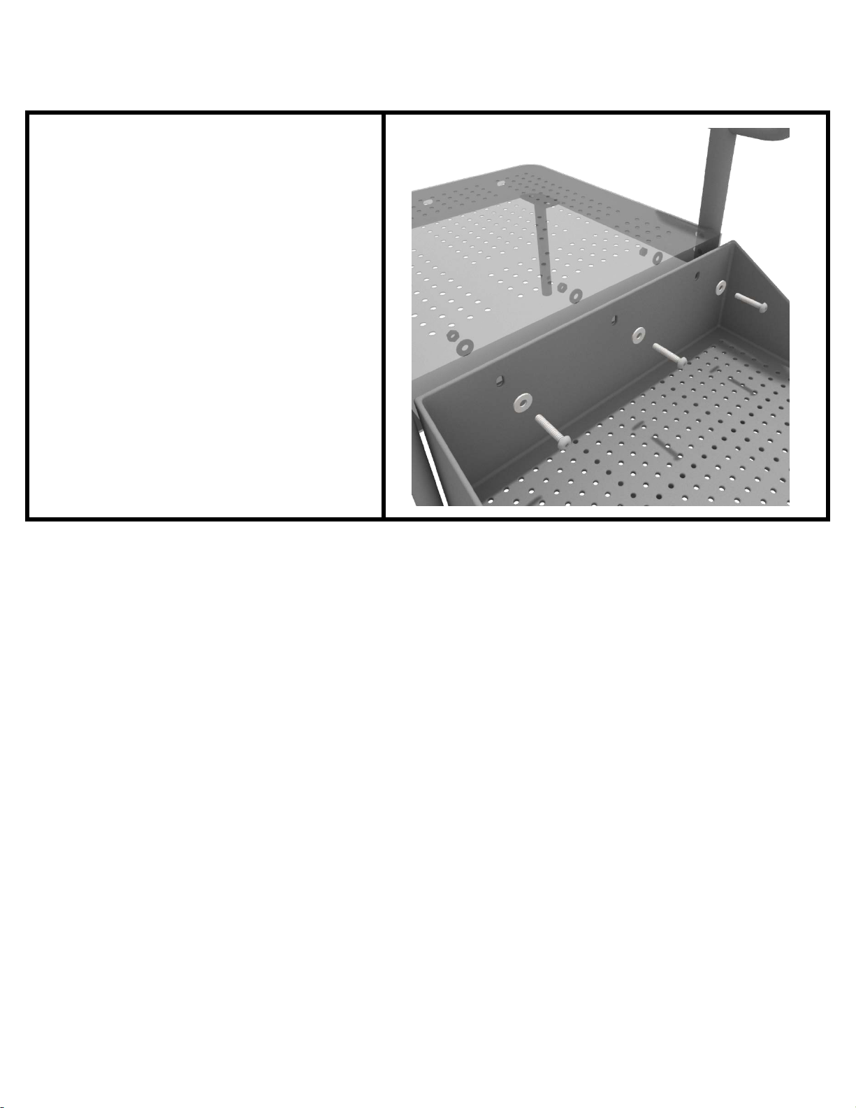
36” Transfer Station (for 3.5” post) Install
STEP: 9
Using three (3) M10*25 bolts, six (6)
M10 washers, and three (3) M10
washers, attach the top of the ADA
transfer step to the ADA transfer
deck.
1 Playground Drive Created By: Aaron Price
Greenfield, IN 46140 Date Modified: 3/13/18
1-800-667-0097
Page 5 of 5 (36” Transfer Station (for 3.5” post) Install)
Page 21
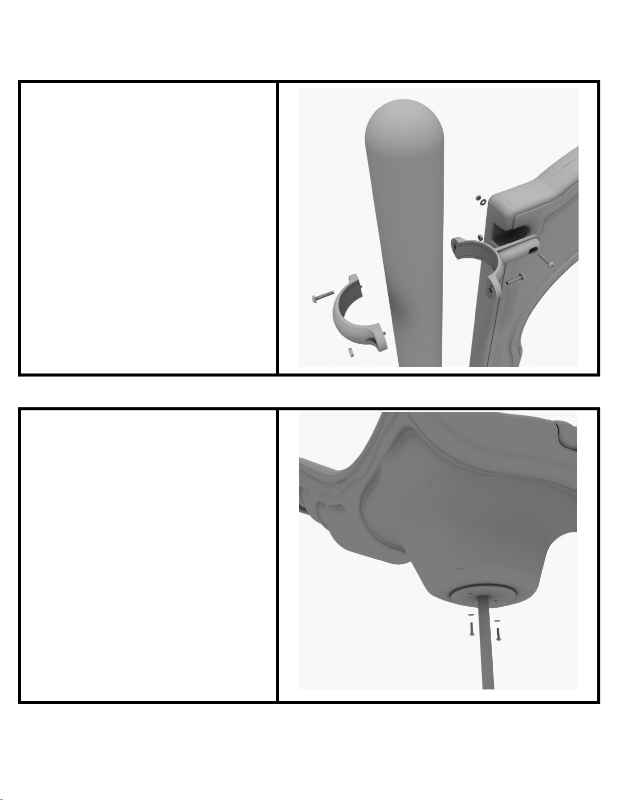
3-foot Single Wave Slide Installation
STEP: 1
Take one (1) 3.5-inch flat clamp, and
loosely attach it around a post using
the bolts and nuts provided in the
clamp hardware bag. Repeat this
process on the other post. Then, use
one (1) M8*40 bolt, one (1) M8
washer, and one (1) M8 lock nut to
attach each side of the slide hood to
each clamp. Leave bolts loose until
slide is in place.
STEP: 2
See general installation guide
regarding footing information for the
slide end mount. Using two (2)
M8*20, two (M8) spring washers.
And two (2) M8 washers, attach the
slide to the slide support post.
1 Playground Drive Created By: Aaron Price
Greenfield, IN 46140 Date: 3/19/2018
1-800-667-0097
Page 1 of 2 (3-foot Single Wave Slide Installation)
Page 22
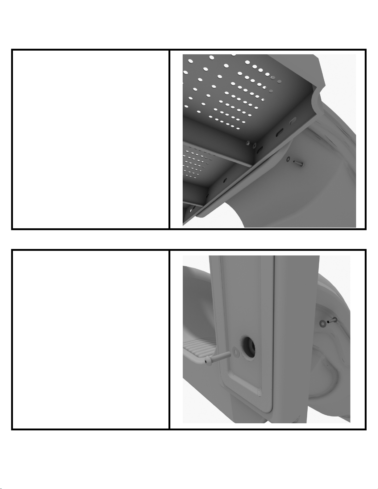
3-foot Single Wave Slide Installation
STEP: 3
To attach a single slide to a deck, use
two (2) M10*45 bolts, four (4) M10
washers, and two (2) M10 lock nuts.
Repeat this process for the other side
of the slide. Repeat this process for
each single slide.
STEP: 4
Using two (2) M8*45 bolts, two (2)
M8 washer, two (2) M12 washers,
and one (1) M12 inner hex spiral nut,
attach the slide to the slide hood.
Repeat this process for the other side
of the slide.
1 Playground Drive Created By: Aaron Price
Greenfield, IN 46140 Date: 3/19/2018
1-800-667-0097
Page 2 of 2 (3-foot Single Wave Slide Installation)
Page 23
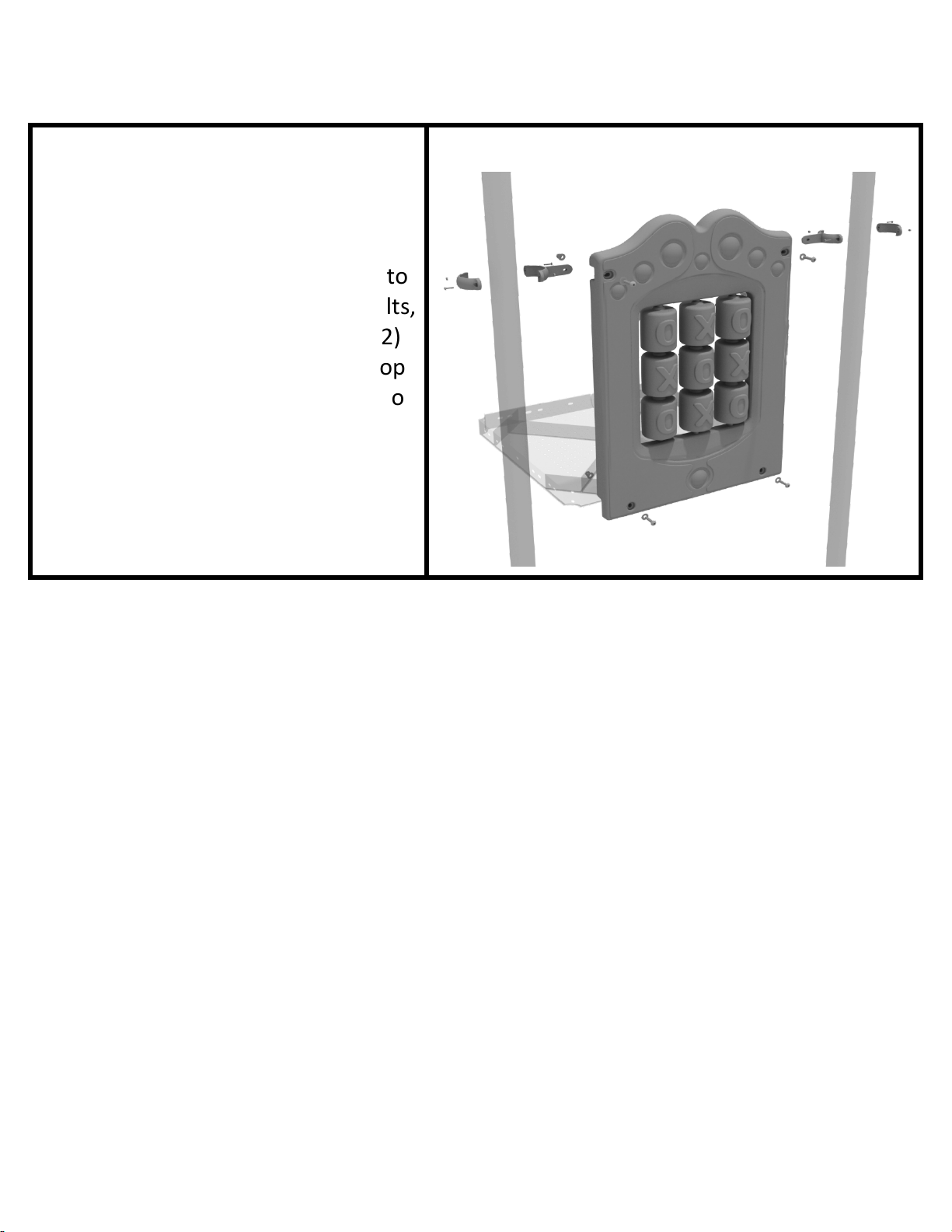
3.5-inch Tic Tac Toe Panel Installation
STEP: 1
Connect the bottom of the panel to
the deck using two (2) M10*50 bolts,
four (4) M10 washers, and two (2)
M10 lock nuts. Then attach the top
of the panel to the posts using two
(2) flat clamps.
1 Playground Drive Created By: Aaron Price
Greenfield, IN 46140 Date: 03/23/2018
1-800-667-0097
Page 1 of 1 (3.5-inch Tic Tac Toe Panel Installation)
Page 24
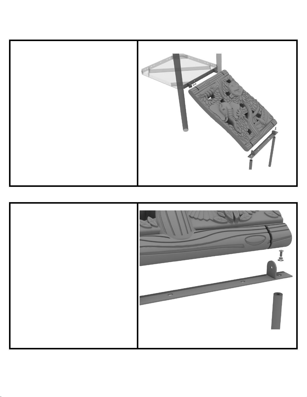
Jungle Climber Installation
STEP: 1
First, detach the pre-attached
bracket on the end of the climber
that has four (4) Bolts attached, and
attach it to the designated deck.
STEP: 2
Then, attach the provided support
mounts to the other side of the
Jungle Climber using the pre-
attached bolt. See general
installation guide regarding footing
information for the figure climber.
1 Playground Drive Created By: Derick H
Greenfield, IN 46140 Date: 09/12/2018
1-800-667-0097
Page 1 of 2
(Jungle Climber Installation)
Page 25
Jungle Climber Installation
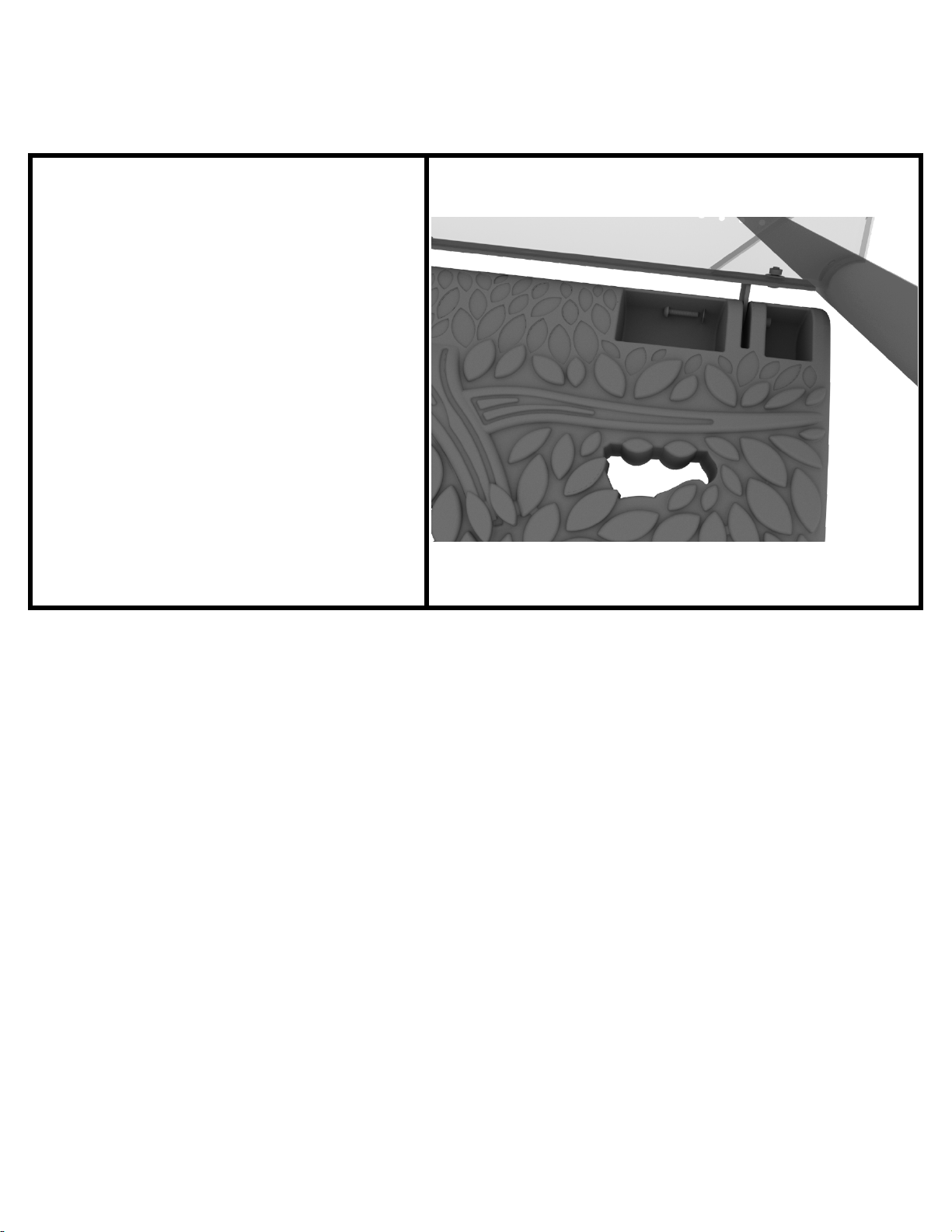
STEP: 3
Finally, re-attach the climber back to
the mounting plate using the original
pre-attached hardware.
1 Playground Drive Created By: Derick H
Greenfield, IN 46140 Date: 09/12/2018
1-800-667-0097
Page 2 of 2
(Jungle Climber Installation)
Page 26
3.5-inch 4-Clamp Arch Rail Installation
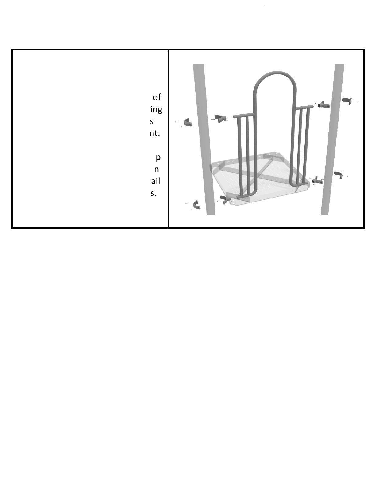
STEP: 1
Attach the Arch Rail to the
designated posts by connect half of
the tube clamp to the arch rail using
one (1) M8*30 bolt. Repeat this
process for each attachment point.
Set the arch rail into place, then
attach the second half of the clamp
around the post. The gap between
the deck and the bottom of the rail
should be no more than 3 inches.
1 Playground Drive Created By: Aaron Price
Greenfield, IN 46140 Date: 03/20/2018
1-800-667-0097
Page 1 of 1 (3.5-inch 4-Clamp Arch Rail Installation)
Page 27
Ships Wheel Installation
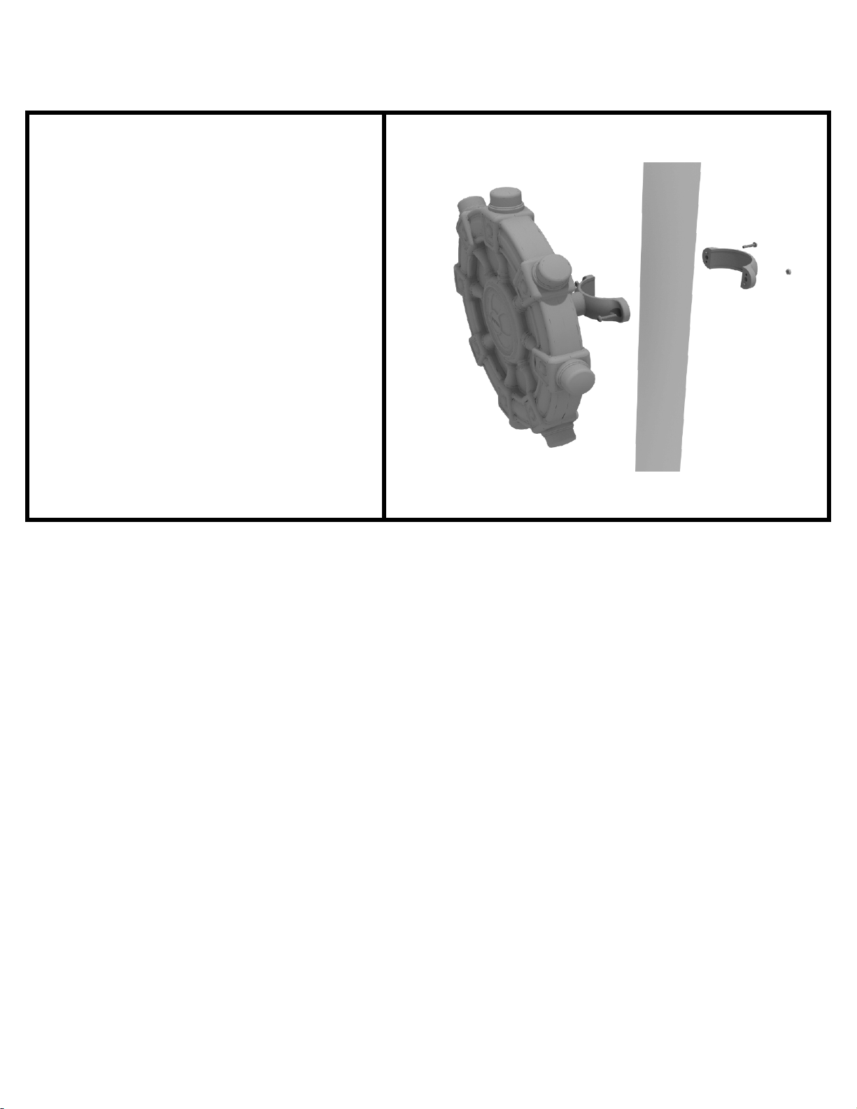
Detach half of the tube clamp
connected to the Ships Wheel, and
re-attach the clamp around the
support post, as shown in the
picture. Recommended install height
is 20 to 36 inches above surfacing
depending on age range.
We recommend using Thread-
locking fluid on bolts connecting
Ship's wheel to clamp to prevent
hardware from loosening over time.
(Thread-locker not supplied)
1 Pla
yground Drive Created By: Aaron Price
Greenfield, IN 46140 Date: 03/20/2018
1-800-667-0097
Page 1 of 1 (Ships Wheel Installation)
 Loading...