

Page 1
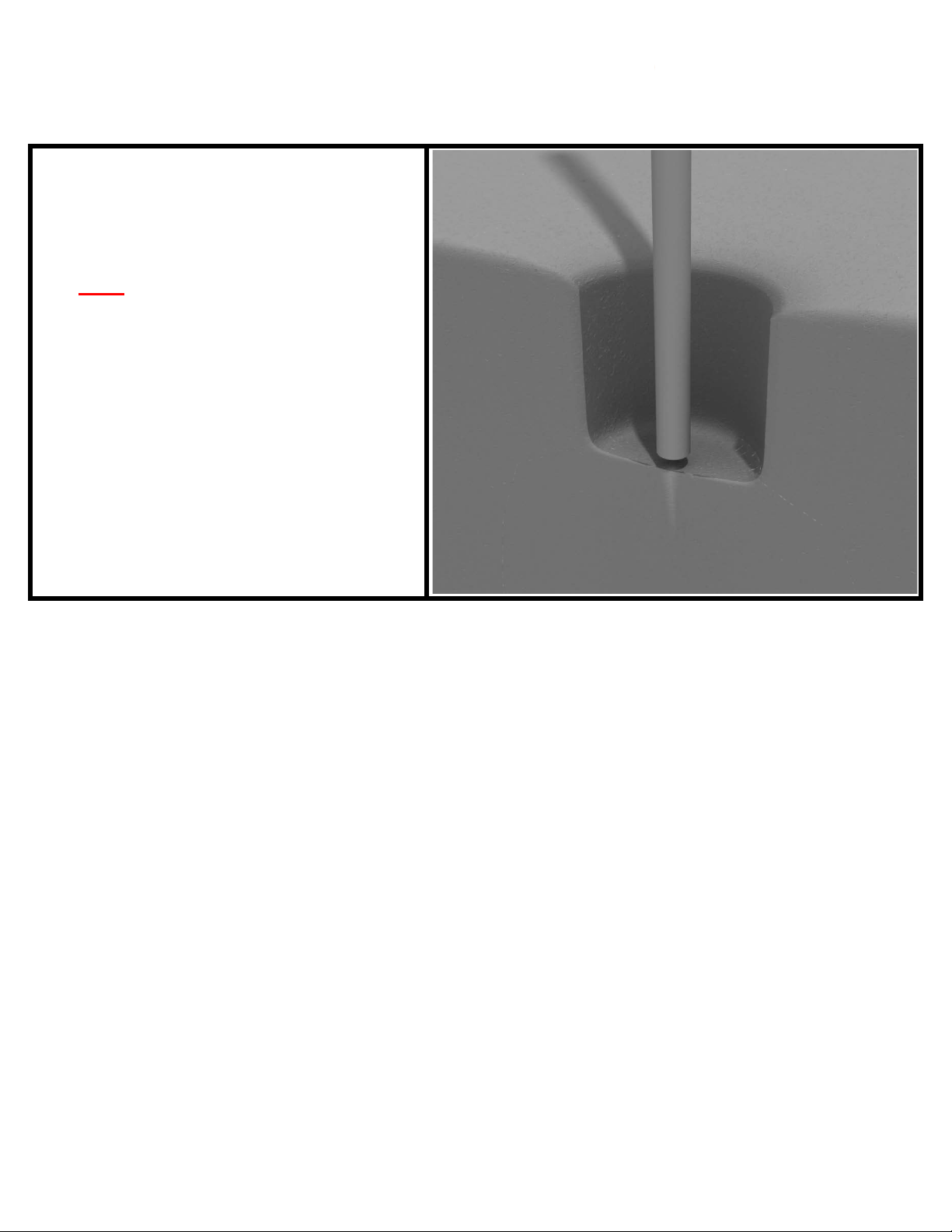
Post Installation
STEP: 1
DO NOT CEMENT POSTS INTO PLACE
UNTIL THE ENTIRE STRUCTURE IS
ASSEMBLED.
Refer to the General Installation
guide footing information and dig
proper holes for the support posts.
10859 Washington St. Suite 200
Indianapolis, IN
1-800-667-0097
Created By: Aaron Price
Date: 04/26/2018
Page 1 of 1 (Post Installation)
Page 2

Square Deck Installation
STEP: 1
After the posts are in place, using
four (4) M10*35 bolts, eight (8) M10
washers, and four (4) M10 lock nuts,
attach each square deck to each preattached deck clamp as shown in the
image.
D
eck clamps are pre-attached to the
posts and should not be altered in
any way.
10859 Washington St. Suite 200
Indianapolis, IN
1-800-667-0097
Page 1 of 1 (Square Deck Installation)
Created By: Aaron Price
Date: 3/19/2018
Page 3
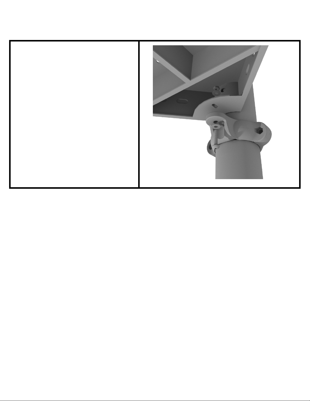
Rectangle Deck Installation
STEP: 1
After the posts are in place, using
four (4) M10*35 bolts, eight (8) M10
washers, and four (4) M10 lock nuts,
attach the rectangle deck to each
pre-attached deck clamp as shown in
the image.
D
eck clamps are pre-attached to the
posts and should not be altered in
any way.
10859 Washington St. Suite 200
Indianapolis, IN
1-800-667-0097
Page 1 of 1 (Rectangle Deck Installation)
Created By: Aaron Price
Date: 03/19/2018
Page 4

3.5-inch Clamp Installation Guide
3.5-inch Flat Clamp
Connect half of the flat clamp to the
component using one (1) M8*40
bolt. Then, using the other half of the
flat clamp and the hardware
provided in the clamp hardware bag,
attach the other half of the tube
clamp around the post.
3.5-inch Tube Clamp
Connect half of the clamp to the
component using one (1) M8*30
bolt. Then, using the other half of the
tube clamp and the hardware
provided in the clamp hardware bag,
attach the other half of the tube
clamp around the post.
10859 Washington St. Suite 200
Indianapolis, IN
1-800-667-0097
Page 1 of 2 (3.5-inch Clamp Installation Guide)
Created By: Aaron Price
Date: 03/28/2018
Page 5
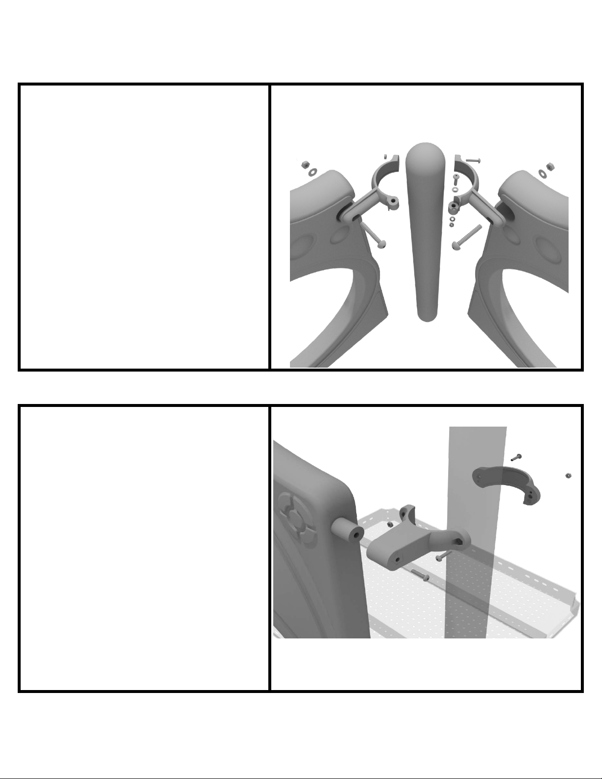
3.5-inch Clamp Installation Guide
3.5-inch 90-Degree Flat Clamp
Connect half of the flat clamp to one
panel using one (1) M8*40 bolt.
Then, using the other half of the flat
clamp and the hardware provided in
the clamp hardware bag, attach the
other half of the tube clamp around
the post. Then, attach the next panel
to the other side of the clamp using
the same process.
3.5-inch Double Slide Clamp
Connect half of the double slide
clamp to the double slide hood using
one (1) M8*30 bolt. Then, using the
other half of the clamp and the
hardware provided in the clamp
hardware bag, attach the other half
of the tube clamp around the post.
10859 Washington St. Suite 200
Indianapolis, IN
1-800-667-0097
Page 2 of 2 (3.5-inch Clamp Installation Guide)
Created By: Aaron Price
Date: 03/28/2018
Page 6
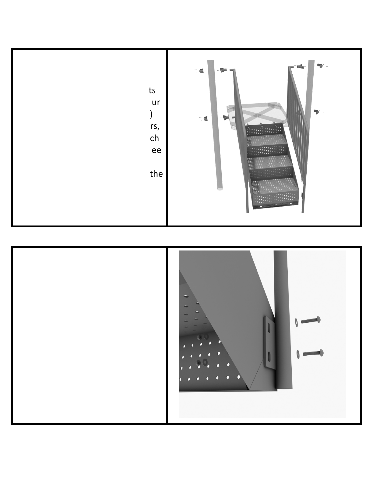
48” Transfer Station (3.5” post) Installation
STEP: 1
Connect the 4-foot Transfer
Handrails to the designated posts
using four (4) tube clamps, and four
(4)M8*30 bolts. Using three (3)
M10*25 bolts, six (6) M10 washers,
and three (3) M10 lock nuts, attach
the top of the stairs to the deck. See
the general installation guide
regarding footing information for the
handrail and set them into the
ground.
STEP: 2
Using three (3) M10*25 bolts, six (6)
M10 washers, and three (3) M10 lock
nuts, attach the top of the stairs to
the deck. Then using four (4) M10*30
bolts, eight (8) M10 washers, and
four (4) M10 lock nuts, attach the
handrail to the bottom of the stairs.
10859 Washington St. Suite 200
Indianapolis, IN
1-800-667-0097
Page 1 of 4 (48” Transfer Station (3.5” post) Installation)
Created By: Aaron Price
Date: 03/20/2018
Page 7

4-foot Transfer Station Installation
STEP: 3
Using three (3) M10*25 bolts, six (6)
M10 washers, and three (3) M10 lock
nuts, attach the ADA transfer deck to
the base of the 4-foot ADA transfer
stair.
STEP: 4
See general installation guide
regarding footing information for the
transfer deck handrail & mount.
Using t
wo (2) M10*65 bolts, four (4)
M10 washers, and two (2) M10 lock
nuts, attach the transfer handrail to
the ADA transfer deck.
10859 Washington St. Suite 200
Indianapolis, IN
1-800-667-0097
Page 2 of 4 (48” Transfer Station (3.5” post) Installation)
Created By: Aaron Price
Date: 03/20/2018
Page 8
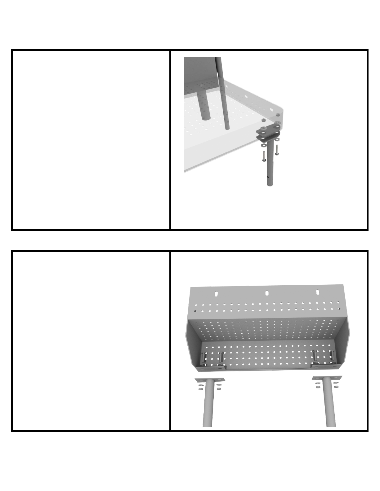
4-foot Transfer Station Installation
STEP: 5
Using two (2) M10*25 bolts, four (4)
M10 washers, and two (2) lock nuts,
attach the transfer deck mount to
the ADA transfer deck.
STEP: 6
See general installation guide
regarding footing information for the
ADA transfer step mount. Using four
(4) M10 bolts, eight (8) M10 washers,
and four (4) M10 lock nuts, attac
th
e transfer step to the ADA transfer
step mount.
h
10859 Washington St. Suite 200
Indianapolis, IN
1-800-667-0097
Page 3 of 4 (48” Transfer Station (3.5” post) Installation)
Created By: Aaron Price
Date: 03/20/2018
Page 9
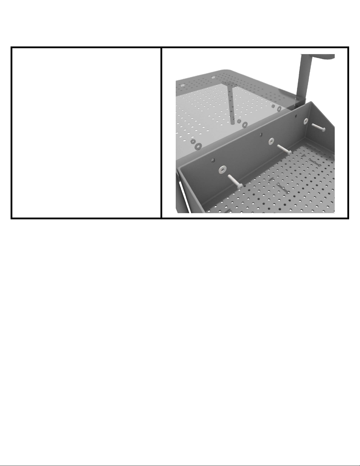
4-foot Transfer Station Installation
STEP: 7
Using three (3) M10*25 bolts, six (6)
M10 washers, and three (3) M10
washers, attach the top of the ADA
transfer step to the ADA transfer
deck.
10859 Washington St. Suite 200
Indianapolis, IN
1-800-667-0097
Page 4 of 4 (48” Transfer Station (3.5” post) Installation)
Created By: Aaron Price
Date: 03/20/2018
Page 10

2-foot Middle Stair Installation
STEP: 1
Using eight (8) M10*25 bolts, sixteen
(16) M10 washers, and eight (8) M10
lock nuts, attach the 2-foot
connection stair to the assigned
decks.
STEP: 2
Then, once the stair is in place,
attach the 2-foot connection handrail
to the posts using four (4) 3.5-inch
tube clamps, and four (4) M8*30
bolts. Then, attach the bottom of the
handrails to the decks using one (1)
M10*25 bolt, two (2) M10 washers,
and one (1) M10 lock nut for each
attachment point.
10859 Washington St. Suite 200
Indianapolis, IN
1-800-667-0097
Page 1 of 1 (2-foot Middle Stair Installation)
Created By: Aaron Price
Date: 03/21/2018
Page 11
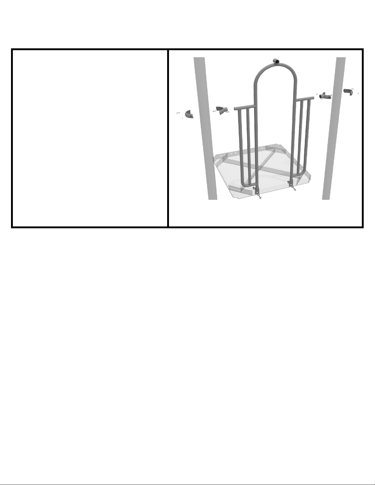
3.5-inch 2-Clamp Arch Rail Installation
STEP: 1
Attach the Arch Rail to the
designated posts by connect half of
the tube clamp to the arch rail using
one (1) M8*30 bolt. Repeat this
process for each post attachment
point. Then, attach the rail to the
deck using two (2) M10*25 bolts,
four (4) M10 washers, and two (2)
M10 lock nuts. Finally, attach the
second half of the clamp around the
post.
10859 Washington St. Suite 200
Indianapolis, IN
1-800-667-0097
Page 1 of 1 (3.5-inch 2-Clamp Arch Rail Installation)
Created By: Aaron Price
Date: 04/04/2018
Page 12
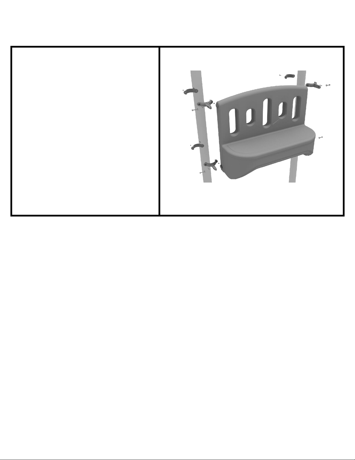
3.5inch Bench Panel Installation
Attach the Bench Panel to the
designated posts using four (4) 3.5-
inch flat clamps, and four (4) M8*25
bolts.
STEP: 1
10859 Washington St. Suite 200
Indianapolis, IN
1-800-667-0097
Page 1 of 1 (3.5inch Bench Panel Installation)
Created By: Aaron Price
Date: 03/21/2018
Page 13
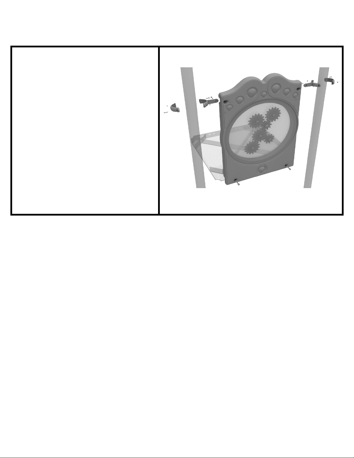
3.5-inch Gear Panel Installation
Connect the bottom of the panel to
the deck using two (2) M10*50 bolts,
four (4) M10 washers, and two (2)
M10 lock nuts. Then attach the top
of the panel to the posts using two
(2) flat clamps.
STEP: 1
10859 Washington St. Suite 200
Indianapolis, IN
1-800-667-0097
Page 1 of 1 (3.5-inch Gear Panel Installation)
Created By: Aaron Price
Date: 03/23/2018
Page 14

3.5-inch Metal Barrier Installation
STEP: 1
Attach the metal barrier to the
designated posts using two (2) tube
clamps two (2) M8*30 bolts. Then,
attach the bottom of the metal
barrier to the deck using two (2)
M10*25 bolts, four (4) M10 washers,
and two (2) M10 lock nuts.
10859 Washington St. Suite 200
Indianapolis, IN
1-800-667-0097
Page 1 of 1 (3.5-inch Metal Barrier Installation)
Created By: Aaron Price
Date: 04/05/2018
Page 15
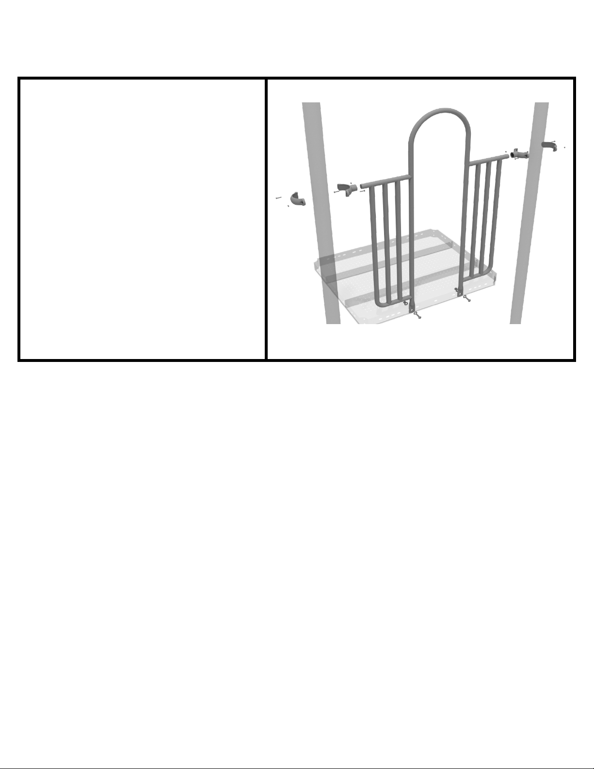
4.5-inch 2-Clamp Arch Rail Installation
STEP: 1
Attach the Arch Rail to the
designated posts by connect half of
the tube clamp to the arch rail using
one (1) M8*30 bolt. Repeat this
process for each post attachment
point. Then, attach the rail to the
deck using two (2) M10*25 bolts,
four (4) M10 washers, and two (2)
M10 lock nuts. Finally, attach the
second half of the clamp around the
post.
10859 Washington St. Suite 200
Indianapolis, IN
1-800-667-0097
Page 1 of 1 (4.5-inch 2-Clamp Arch Rail Installation)
Created By: Aaron Price
Date: 03/21/2018
Page 16

4-foot Double Straight Slide Installation
STEP: 1
Attach the deck climber extension to
the proper deck using four (4)
M10*25 bolts, eight (8) M10
washers, and four (4) M10 lock nuts.
STEP: 2
Then, See general installation guide
regarding footing information for the
double slide end mounts. Using two
(2) M8*20 bolts, two (2) M8 spring
gaskets, and two (2) M8 washers,
attach the slide end mounts to the
double slide.
10859 Washington St. Suite 200
Indianapolis, IN
1-800-667-0097
Page 1 of 2 (4-foot Double Straight Slide Installation)
Created By: Aaron Price
Date: 04/10/2018
Page 17

4-foot Double Straight Slide Installation
STEP: 3
Then, attach the slide to the deck
extension using four (4) M10*45
bolts, eight (8) M10 washers, and
four (4) M10 lock nuts.
STEP: 4
Once the slide is attached, take the
double slide hood and insert hood
into the top of the slide, and then
attach the top using two (2) double
slide clamps, and two (2) M8*30
bolts.
10859 Washington St. Suite 200
Indianapolis, IN
1-800-667-0097
Page 2 of 2 (4-foot Double Straight Slide Installation)
Created By: Aaron Price
Date: 04/10/2018
Page 18
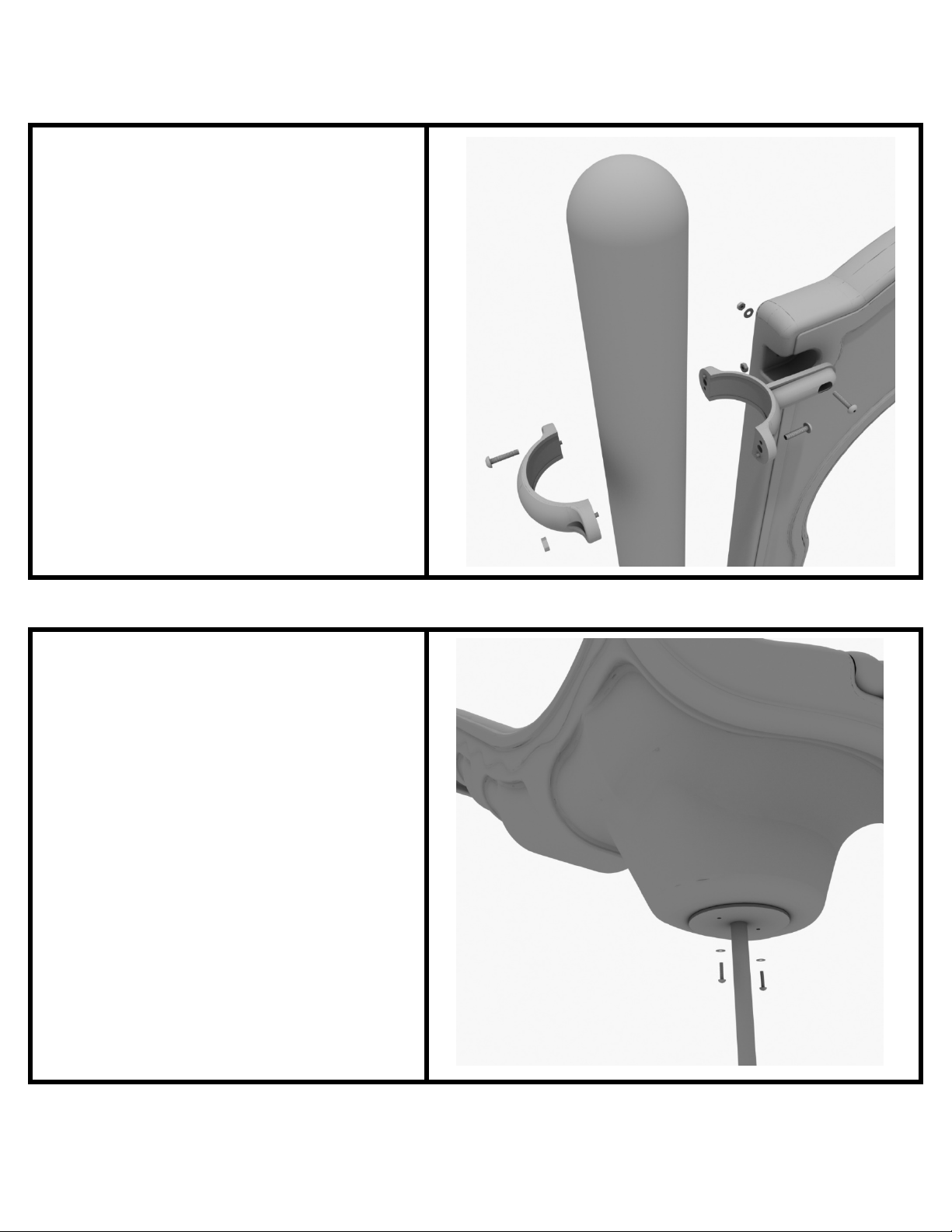
4-foot Left Turn Slide Installation
STEP: 1
Take one (1) 3.5-inch flat clamp, and
loosely attach it around a post using
the bolts and nuts provided in the
clamp hardware bag. Repeat this
process on the other post. Then, use
one (1) M8*40 bolt, one (1) M8
washer, and one (1) M8 lock nut to
attach each side of the slide hood to
each clamp. Leave bolts loose until
slide is in place.
STEP: 2
See general installation guide
regarding footing information for the
slide end mount. Using two (2)
M8*20, two (M8) spring washers.
And two (2) M8 washers, attach the
slide to the slide support post.
10859 Washington St. Suite 200
Indianapolis, IN
1-800-667-0097
Page 1 of 3 (4-foot Left Turn Slide Installation)
Created By: Aaron Price
Date: 04/10/2018
Page 19
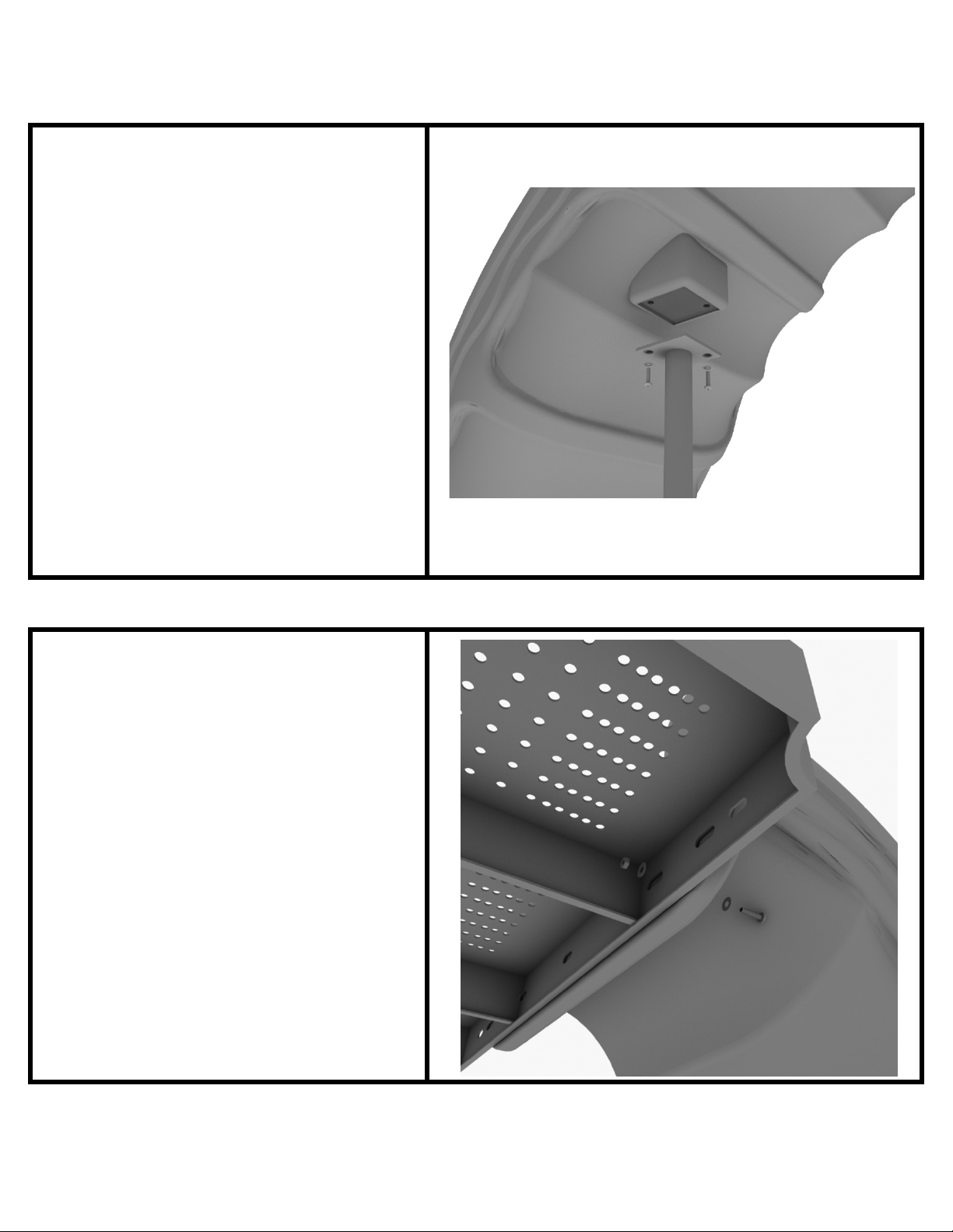
4-foot Left Turn Slide Installation
STEP: 3
See general installation guide
r
egarding footing information for the
middle slide support. Using two (2)
M8*20 bolts, two (2) M8 spring
washers, and two (2) M8 washers,
attach the middle slide support post.
STEP: 4
Using one (1) M10*45 bolt, two (2)
M10 washers, and two (2) M10 lock
nuts, attach one side of the slide to
the deck.
10859 Washington St. Suite 200
Indianapolis, IN
1-800-667-0097
Page 2 of 3 (4-foot Left Turn Slide Installation)
Created By: Aaron Price
Date: 04/10/2018
Page 20

4-foot Left Turn Slide Installation
STEP: 5
Using one (1) M8*45 bolt, one (1) M8
washer, one (1) M12 washer, and
one (1) M12 inner hex spiral nut,
attach the slide to one side of the
slide hood. Repeat this process for
the other side of the slide.
10859 Washington St. Suite 200
Indianapolis, IN
1-800-667-0097
Page 3 of 3 (4-foot Left Turn Slide Installation)
Created By: Aaron Price
Date: 04/10/2018
Page 21

6-foot Single Wave Slide Installation
STEP: 1
Take one (1) 3.5-inch flat clamp, and
loosely attach it around a post using
the bolts and nuts provided in the
clamp hardware bag. Repeat this
process on the other post. Then, use
one (1) M8*40 bolt, one (1) M8
washer, and one (1) M8 lock nut to
attach each side of the slide hood to
each clamp. Leave bolts loose until
slide is in place.
STEP: 2
See general installation guide
regarding footing information for the
slide end mount. Using two (2)
M8*20, two (M8) spring washers.
And two (2) M8 washers, attach the
slide to the slide support post.
10859 Washington St. Suite 200
Indianapolis, IN
1-800-667-0097
Page 1 of 3 (6-foot Single Wave Slide Installation)
Created By: Aaron Price
Date: 03/19/2018
Page 22

6-foot Single Wave Slide Installation
STEP: 3
See general installation guide
regarding footing information for the
middle slide support. Using two (2)
M8*20 bolts, two (2) M8 spring
washers, and two (2) M8 washers,
attach the middle slide support post.
Repeat the process for each middle
slide mount.
STEP: 4
To attach a single slide to a deck, use
two (2) M10*45 bolts, four (4) M10
washers, and two (2) M10 lock nuts.
Repeat this process for the other side
of the slide. Repeat this process for
each single slide.
10859 Washington St. Suite 200
Indianapolis, IN
1-800-667-0097
Page 2 of 3 (6-foot Single Wave Slide Installation)
Created By: Aaron Price
Date: 03/19/2018
Page 23
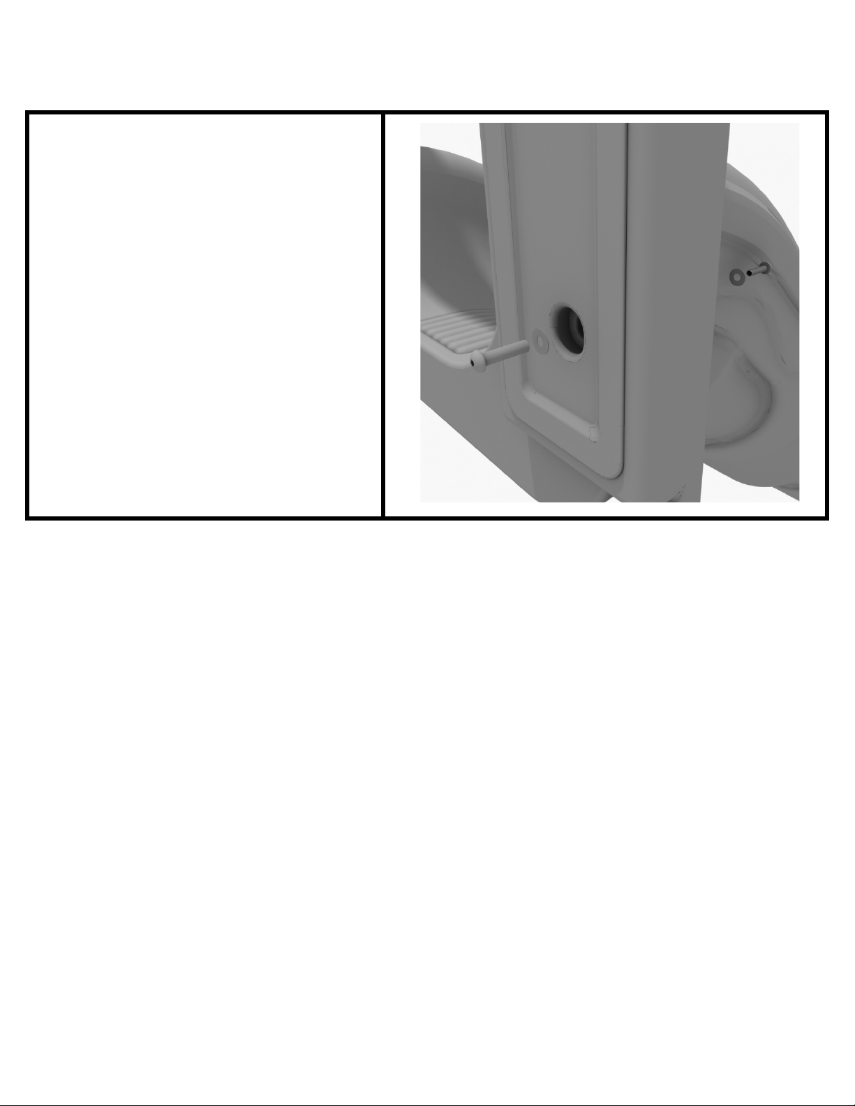
6-foot Single Wave Slide Installation
STEP: 5
Using two (2) M8*45 bolts, two (2)
M8 washer, two (2) M12 washers,
and one (1) M12 inner hex spiral nut,
attach the slide to the slide hood.
Repeat this process for the other side
of the slide.
10859 Washington St. Suite 200
Indianapolis, IN
1-800-667-0097
Page 3 of 3 (6-foot Single Wave Slide Installation)
Created By: Aaron Price
Date: 03/19/2018
Page 24
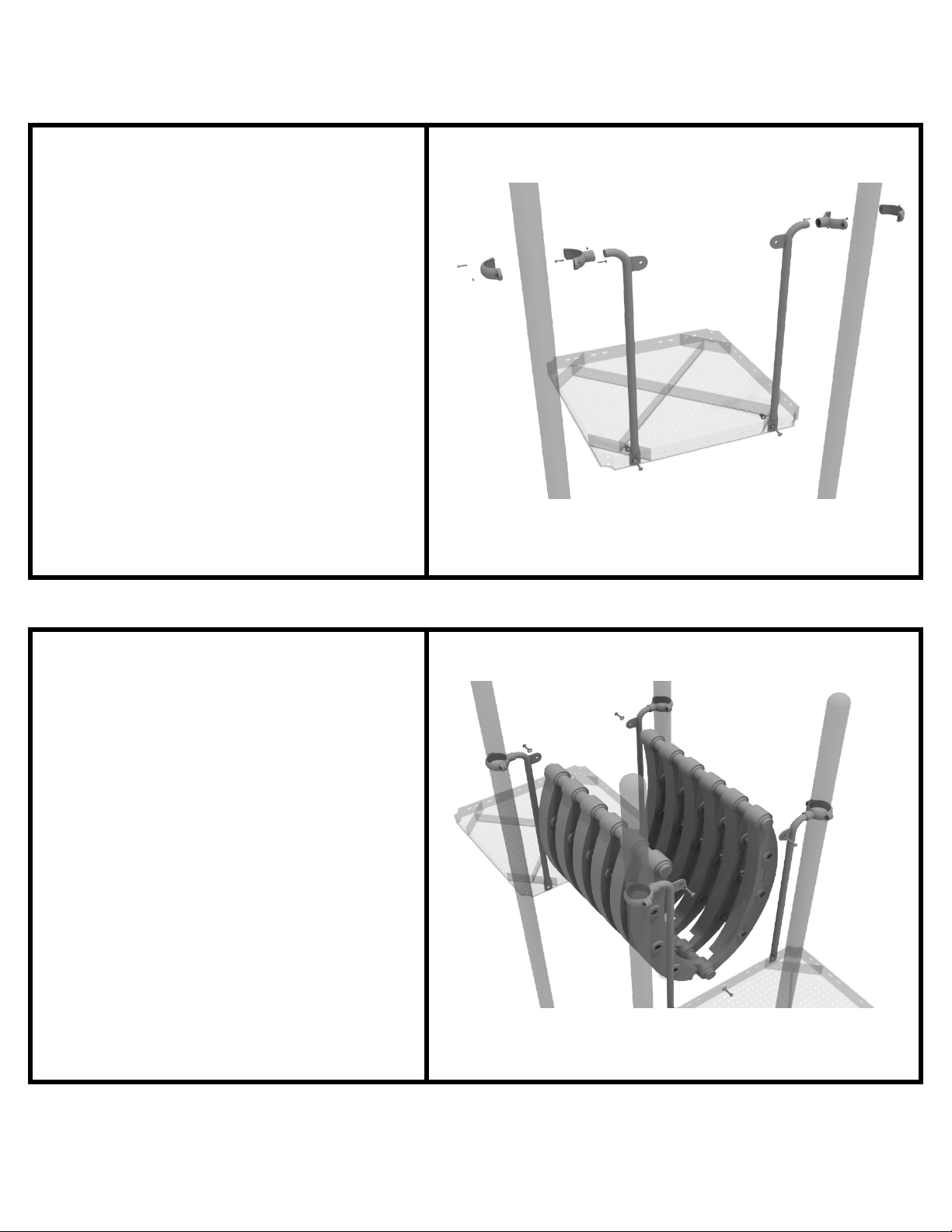
Bones Bridge Installation
STEP: 1
Attach each bones bridge rail to the
proper deck slot using one (1)
M10*25 bolt, one (1) M10 washer,
and (1) M10 lock nut. Then, attach
the top of rails to each post using
one (1) 3.5-inch tube clamp, and one
M8*30 bolt.
STEP: 2
Once the rails are attached, detach
and set aside the pre-attached
hardware on the bottom of the
bones bridge. Attach the bottom of
the bones bridge to each deck using
one (1) M10*30 bolt, one (1) M10
spring gasket, and one (1) M10
washer. Then, attach the top of the
bones bridge to each rail using one
(1) M10*30 bolt, one (1) M10 spring
gasket, and one (1) M10 washer.
10859 Washington St. Suite 200
Indianapolis, IN
1-800-667-0097
Page 1 of 1 (Bones Bridge Installation)
Created By: Aaron Price
Date: 03/21/2018
Page 25

Pod Climber Installation
STEP: 1
See general installation guide
regarding footing information for the
pod climber. Attach the circle end
mount to the bottom of the climber
using the pre-attached hardware.
Each attachment uses three (3)
M10*20 bolts, three (3) M10 spring
gaskets, and one (3) M10 large
gaskets.
STEP: 2
Attach the top of the climber to the
designated arch rail top bracket using
one (1) M10*20 bolt, one (1) M10
spring washer, and one (1) M10
washer.
10859 Washington St. Suite 200
Indianapolis, IN
1-800-667-0097
Page 1 of 1 (Pod Climber Installation)
Created By: Aaron Price
Date: 03/21/2018
Page 26
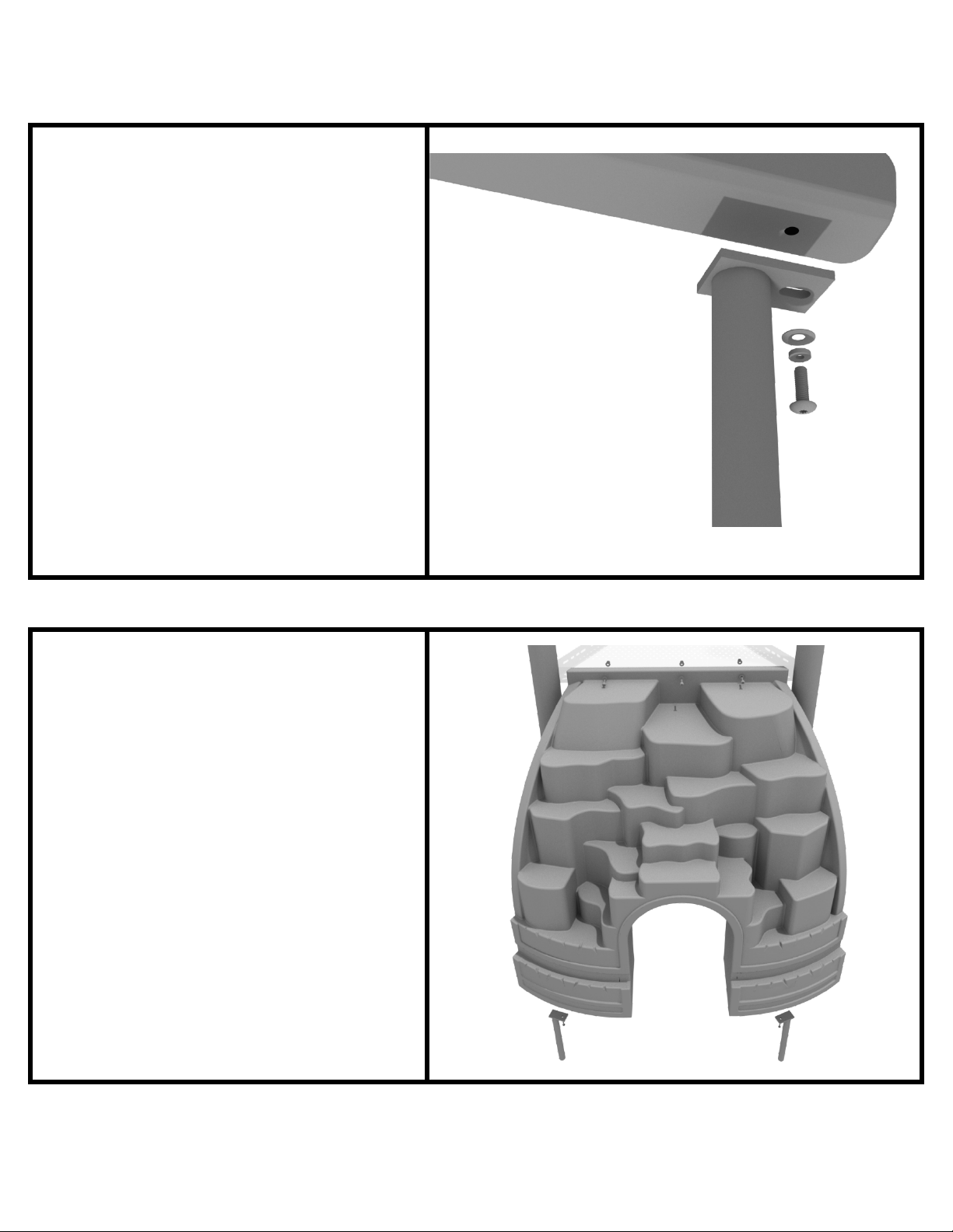
Rock Hole Climber Installation
STEP: 1
See general installation guide
r
egarding footing information for the
Rock Hole climber. Using two (2)
M10*20 bolts, two (2) M10 spring
gaskets, and two (2) M10 washers,
attach the bottom of the rock whole
climber to the climber support posts.
STEP: 1
Then, using three (3) M10*20 bolts,
three (3) M10 spring washers, and
three (3) M10 washers, attach the
Rock hole climber to the deck.
10859 Washington St. Suite 200
Indianapolis, IN
1-800-667-0097
Page 1 of 1 (Rock Hole Climber Installation)
Created By: Aaron Price
Date: 03/22/2018
Page 27
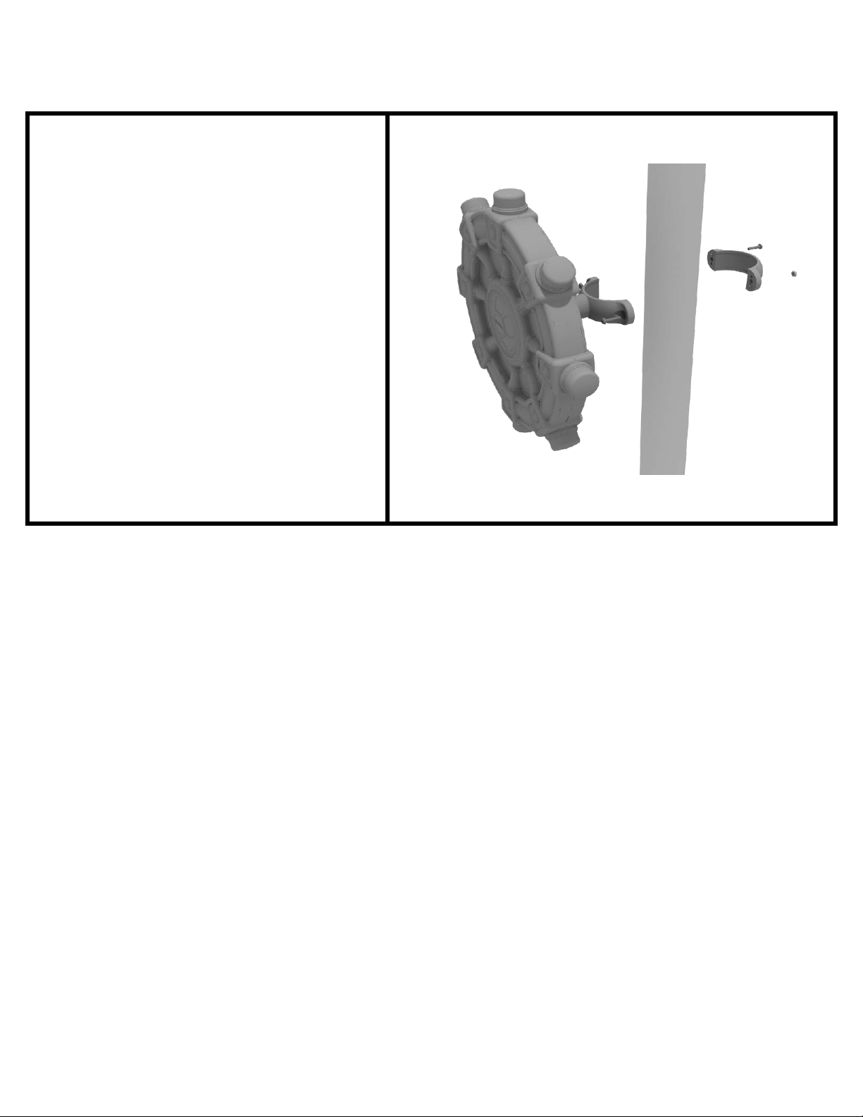
Ships Wheel Installation
Detach half of the tube clamp
connected to the Ships Wheel, and
re-attach the clamp around the
support post, as shown in the
picture. Recommended install height
is 20 to 36 inches above surfacing
depending on age range.
STEP: 1
10859 Washington St. Suite 200
Indianapolis, IN
1-800-667-0097
Page 1 of 1 (Ships Wheel Installation)
Created By: Aaron Price
Date: 03/20/2018
Page 28

Line Roof Installation
STEP: 1
Set the line roof on top of the posts.
Take four (4) self-tapping screws and
drill them through the notch at each
corner of the roof, into the support
posts.
10859 Washington St. Suite 200
Indianapolis, IN
1-800-667-0097
Page 1 of 1 (Line Roof Installation)
Created By: Aaron Price
Date: 03/19/2018
 Loading...